

Combined Behavior of Reinforced Concrete Out-of-Plane Parts Beams Encased with Steel Section


Abstract
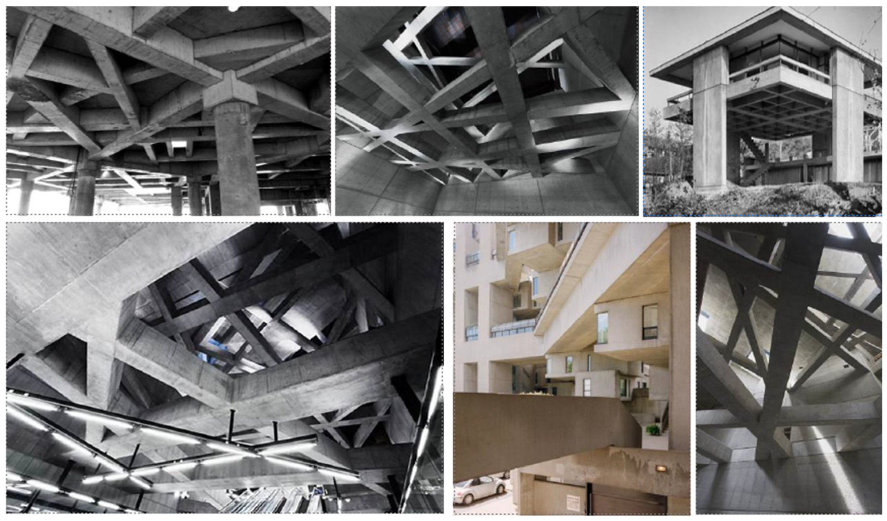
1. Introduction
1.1. Back Ground
1.2. Literature Review
1.3. Gaps in Research
1.4. Aims of Study
- Examine how the quantity and arrangement of out-of-plane components affect the RC beams’ ultimate strength, deflection, rotation, ductility, energy absorption, and failure modes.
- Examine the differences in performance between straight RC beams and RC beams with out-of-plane sections under static loads.
- Assess how well RC beams with out-of-plane portions may be encased in steel sections to improve their structural performance, especially in terms of strength, ductility, and energy absorption.
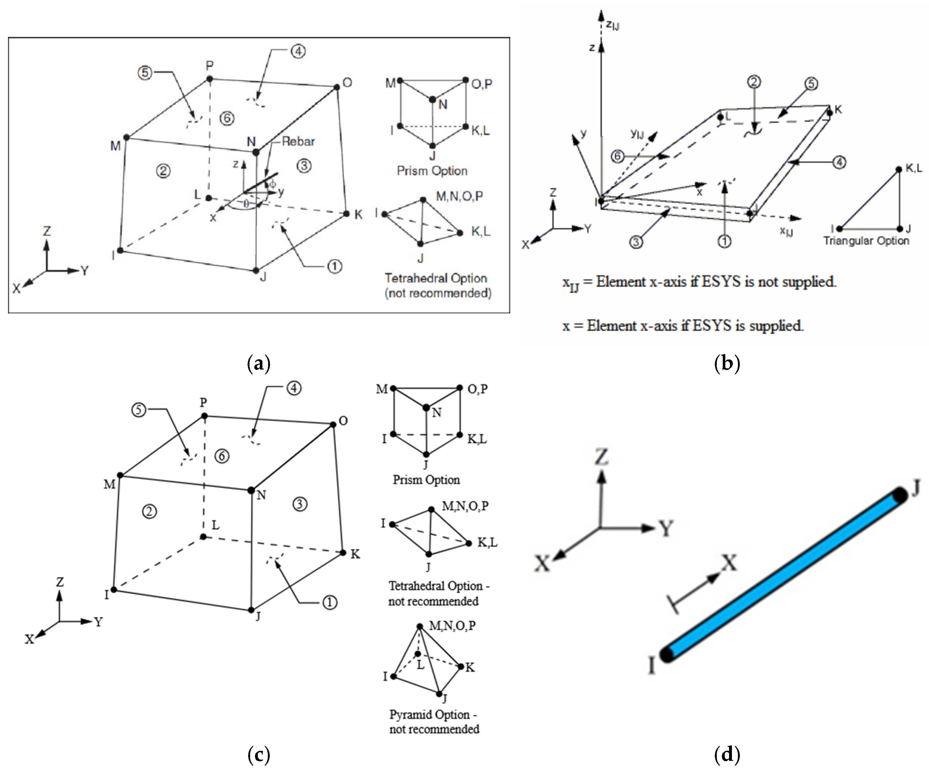
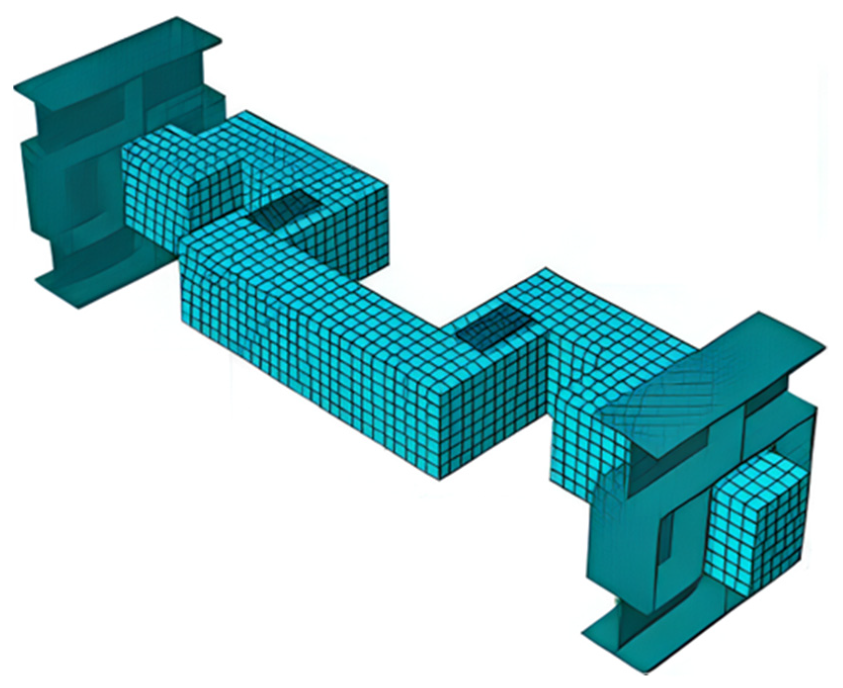
2. Finite Element Modeling
3. Material Modeling
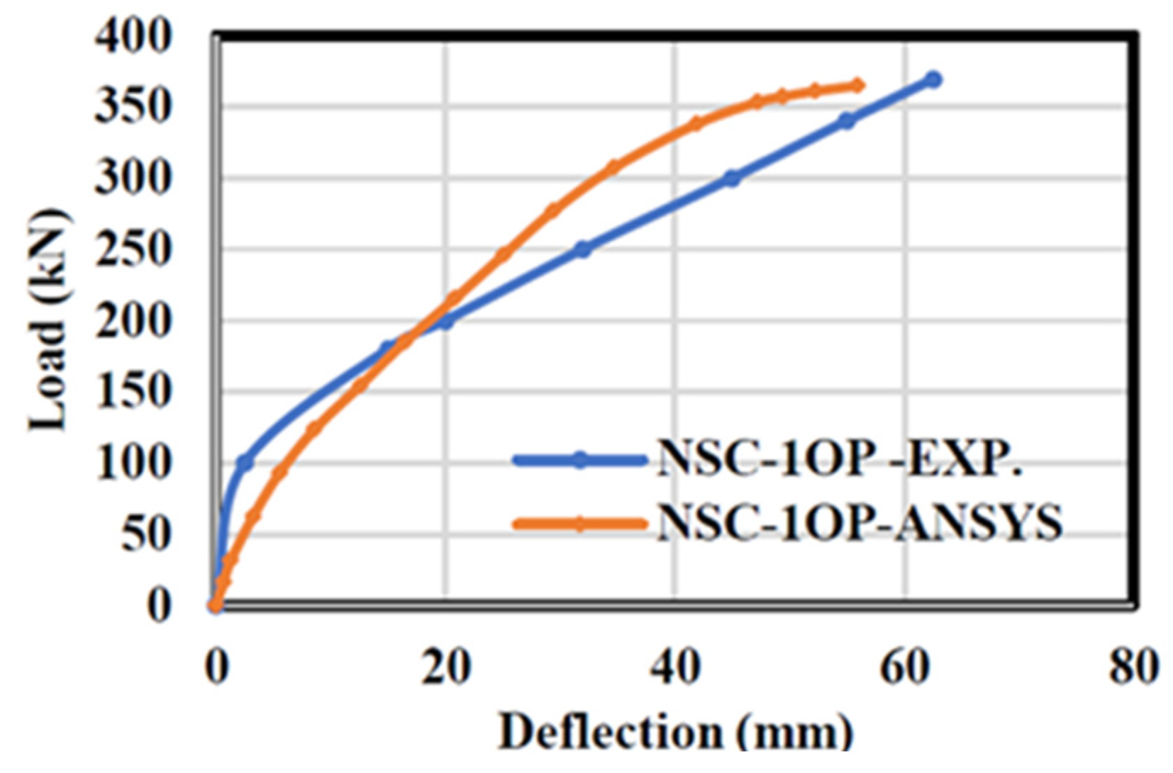
4. Verification Results
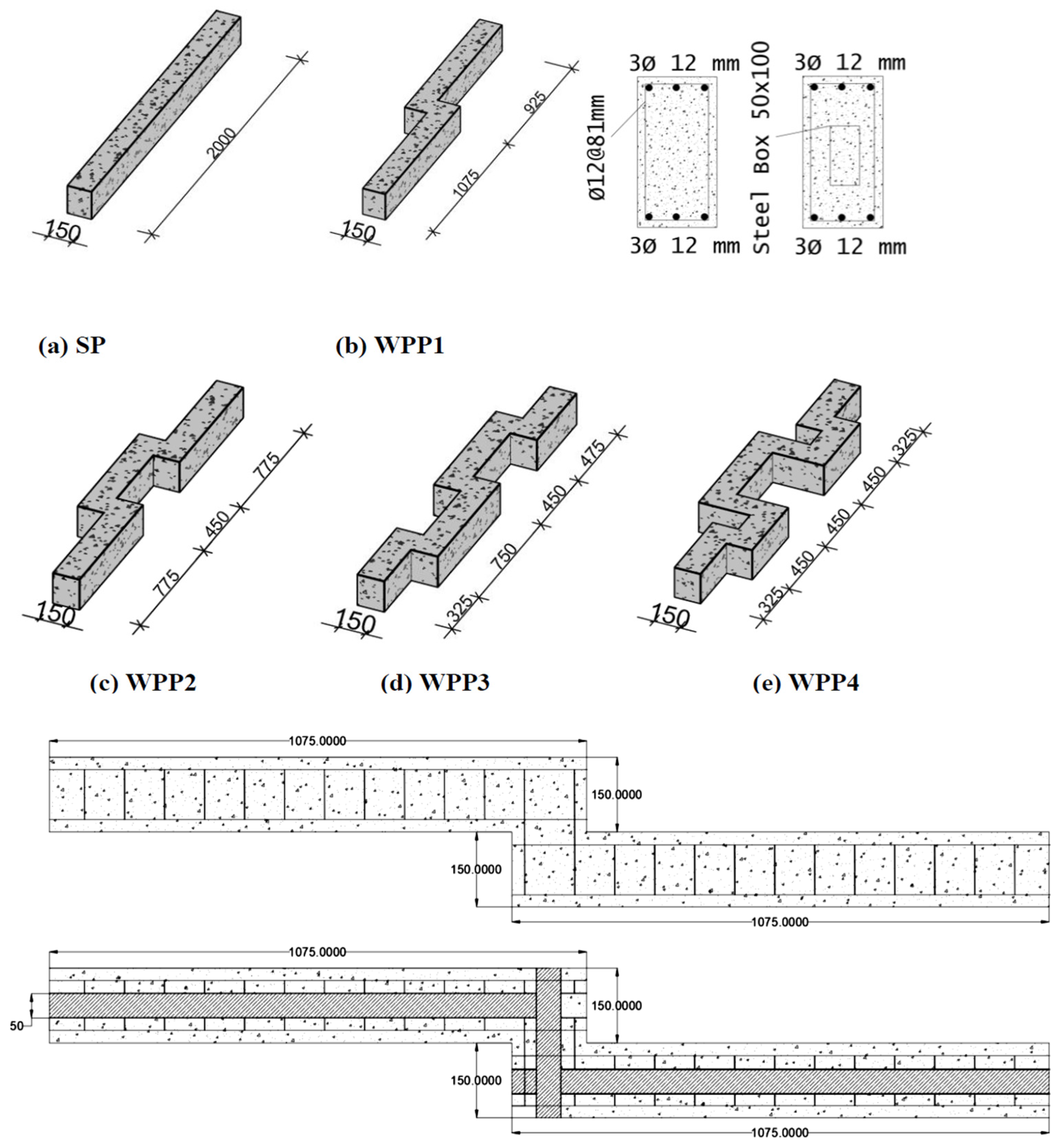
5. Analytical Study
5.1. Test Setup and Boundary Conditions
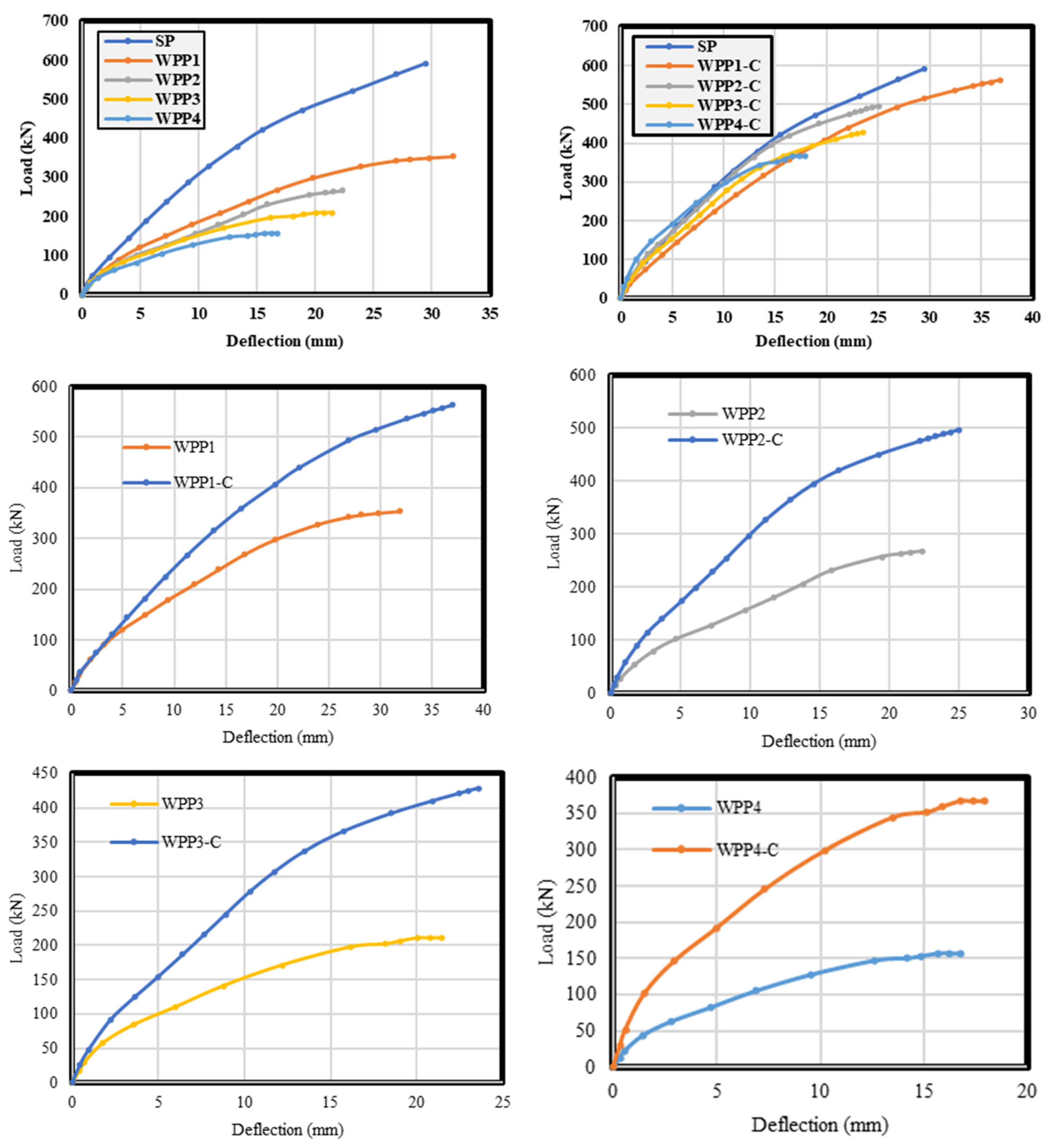
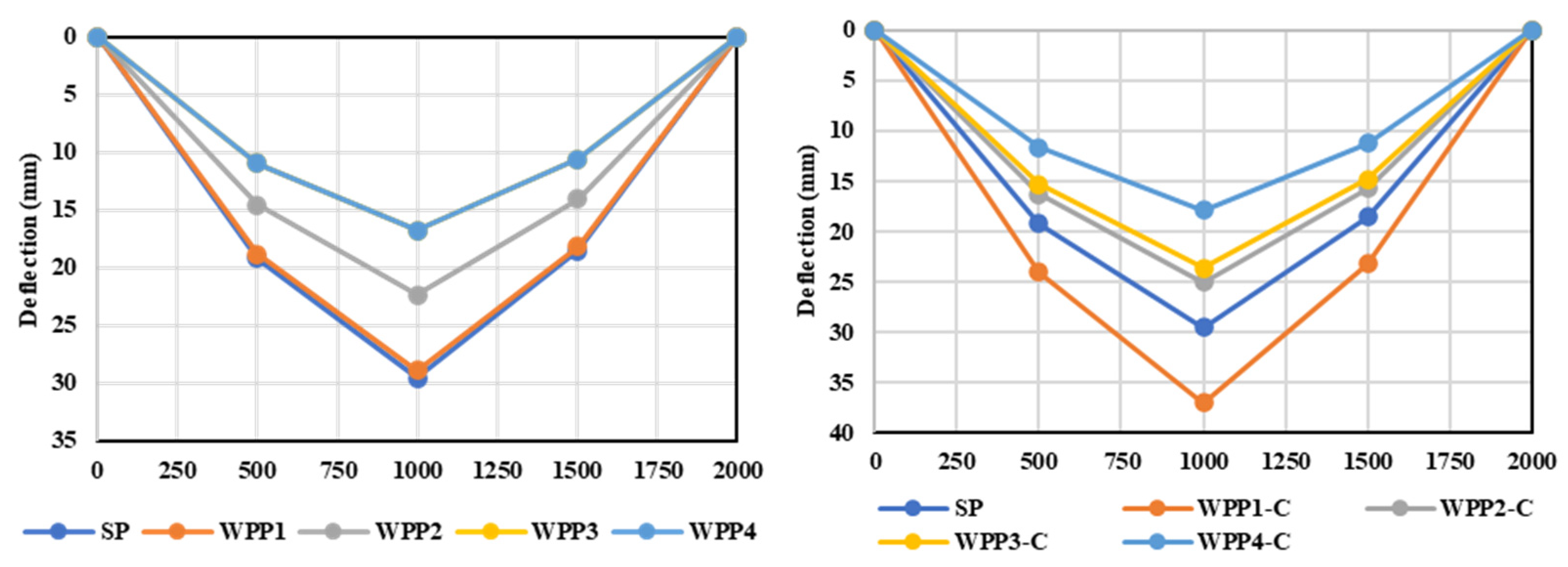
5.2. General Behavior
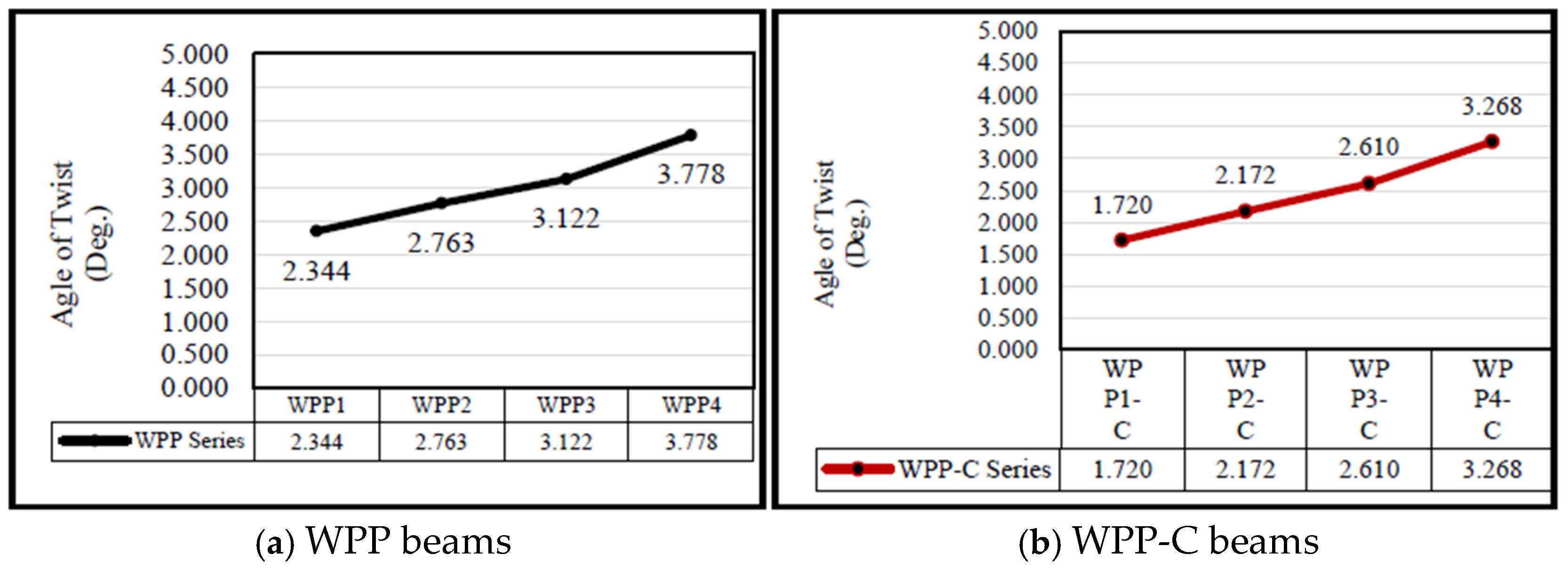
5.3. Twisting Angle
5.4. Effect of Directed Segments
5.5. Effect of Steel Section
5.6. Displacement Ductility Index
5.7. Energy Absorption
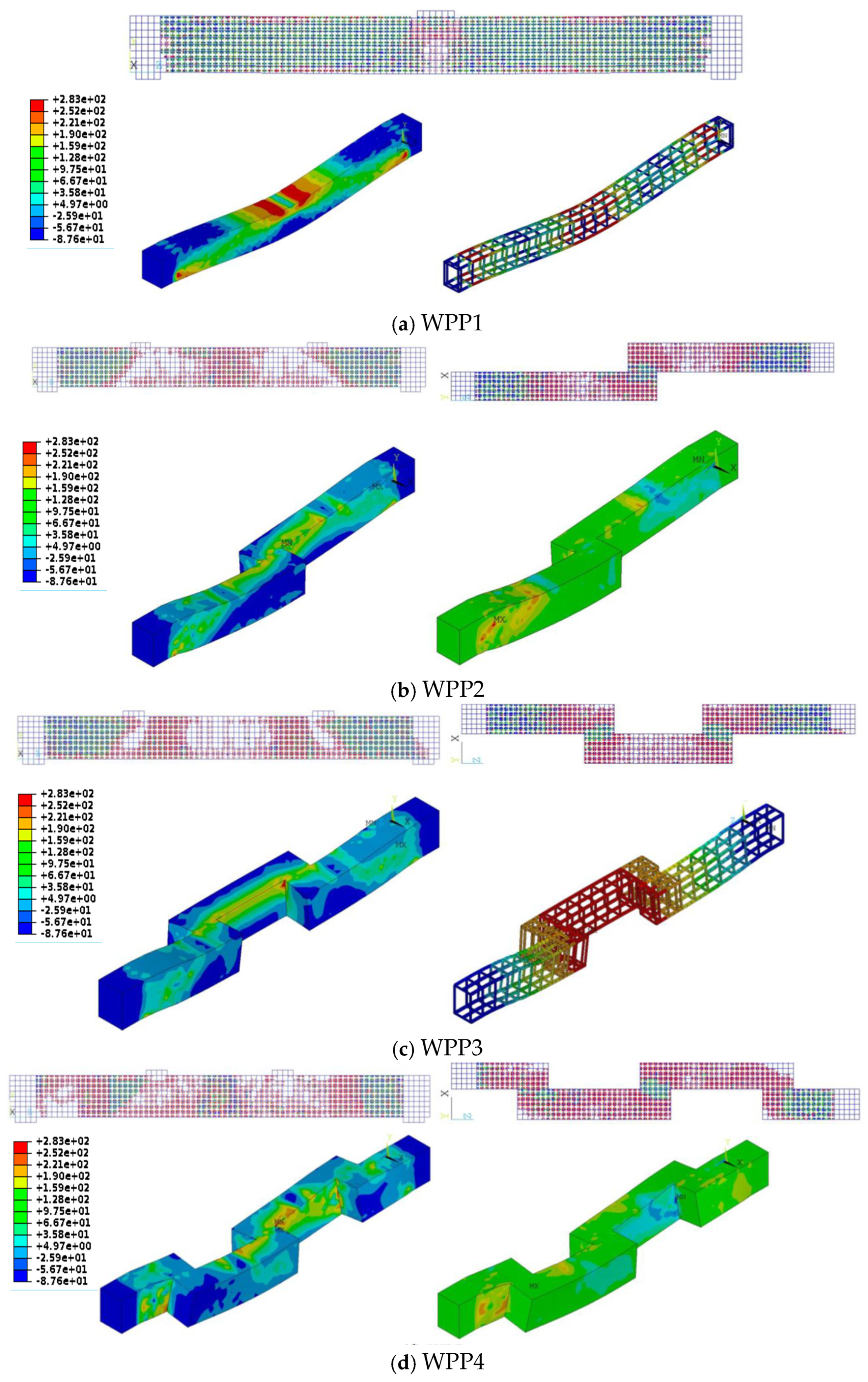
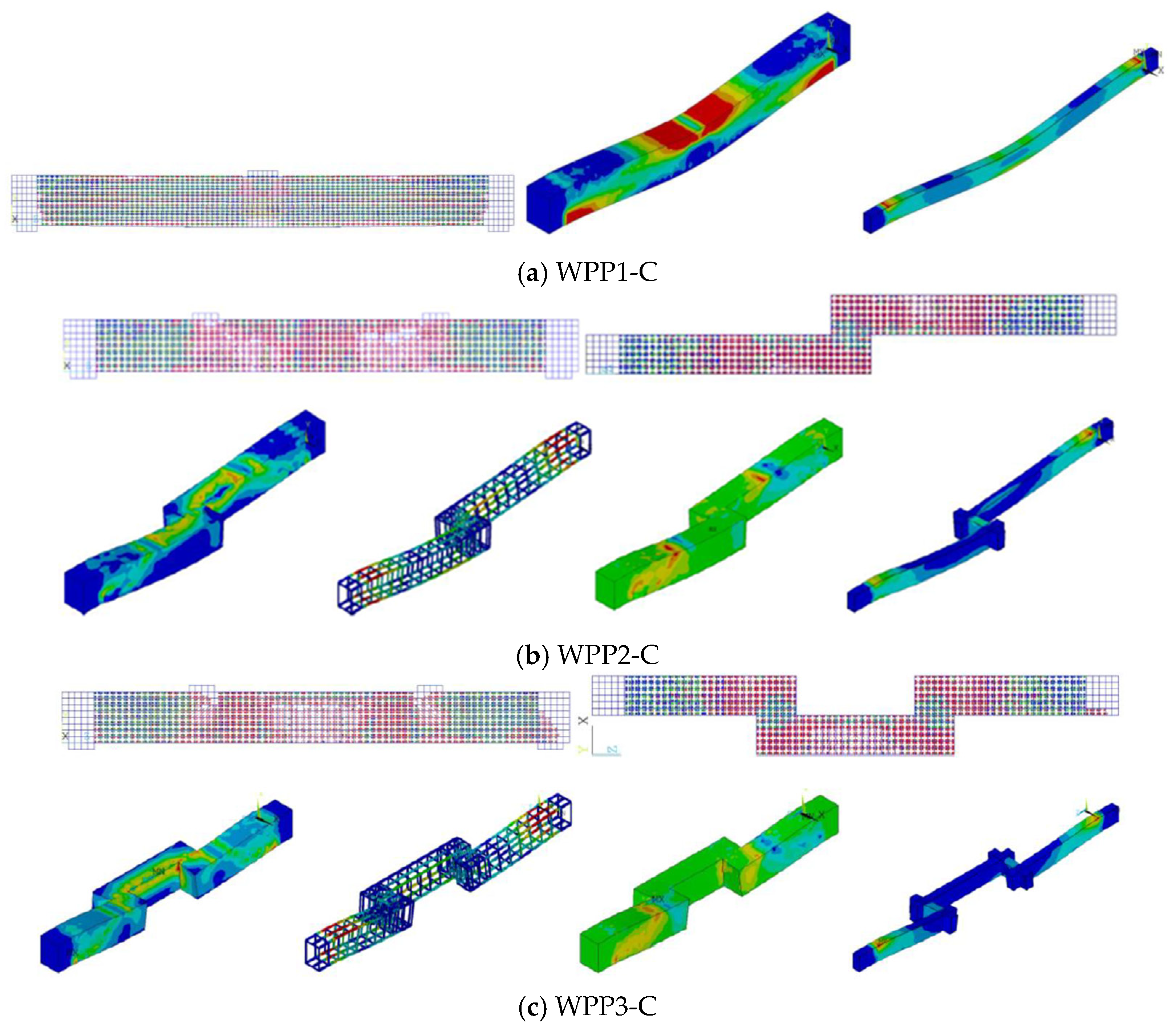
5.8. Cracking Pattern and Stress Distribution
6. Conclusions
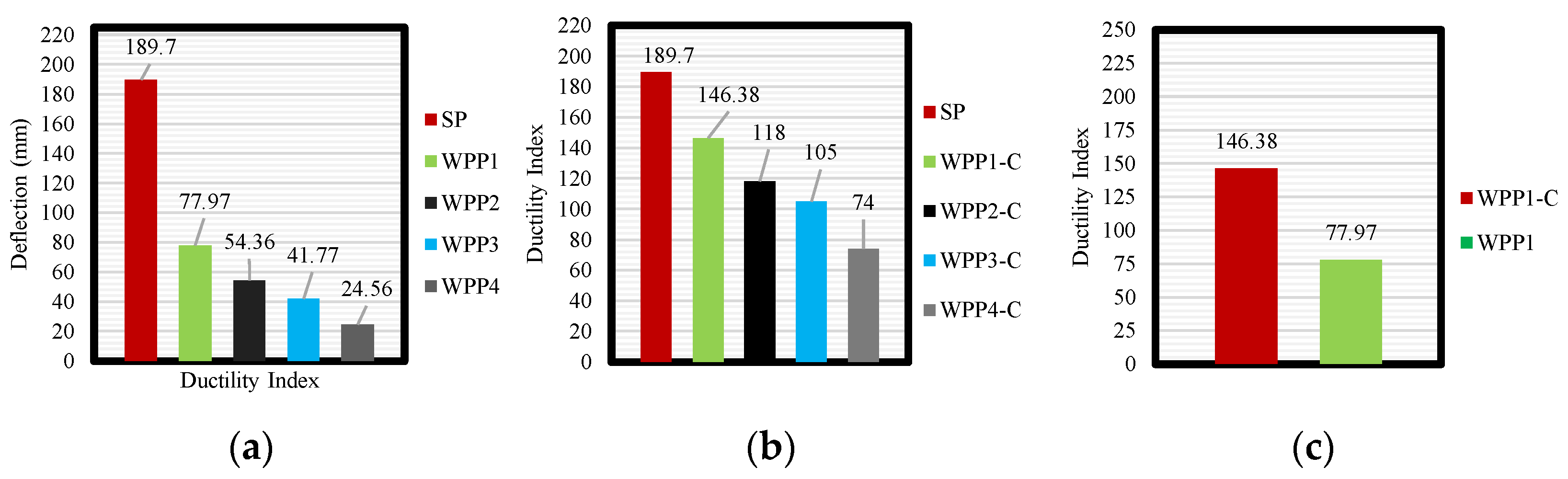
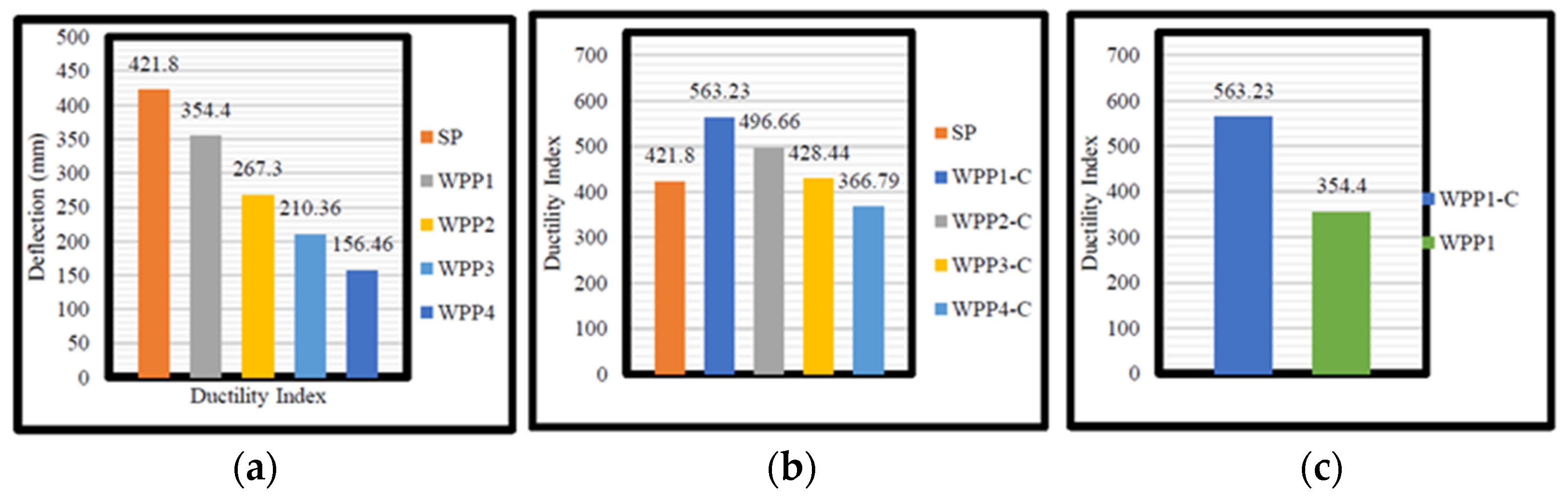
- Changing the configuration of the RC beams from straight to beam out-of-plane parts reduced the ultimate load-carrying capacity by an average value of 41.4% compared with the consecutive beams. For the deflection, the reduction was by 24.3%.
- Testing the WPP beams under static loading with variable segments number showed that increasing the number of segments increased the torsional–shear stresses along the beam.
- Encasing the beams’ out-of-plane parts with steel sections enhanced the ultimate load-carrying capacity and deflection of the WPP beams, compensating for the loss the occurred due to the discontinuities of the concrete segments by gaining an additional strength of 9.9%. The deflection reduction was only 24.3% to 12.4%, which was considered an index in enhancing the ductility of these beams.
- Regarding the stress distribution of reinforced concrete (RC) beams, the straight beam failed in flexure, and the shear stress developed near the support and moved at an inclination of 45 degrees toward the applied load zone. For the WPP beams, the shear stress developed near the supports and moved away toward the stepped section that connected the concrete segments, with the highest shear stress concentration occurring at the top fiber of the segments. For the shear and torsional stresses along the beam span, the shear stresses were typically the highest at the supports due to the concentrated reactions. At the bottom fiber of the beam at midspan, the shear stresses generally were the lowest as the torsional stresses increased.
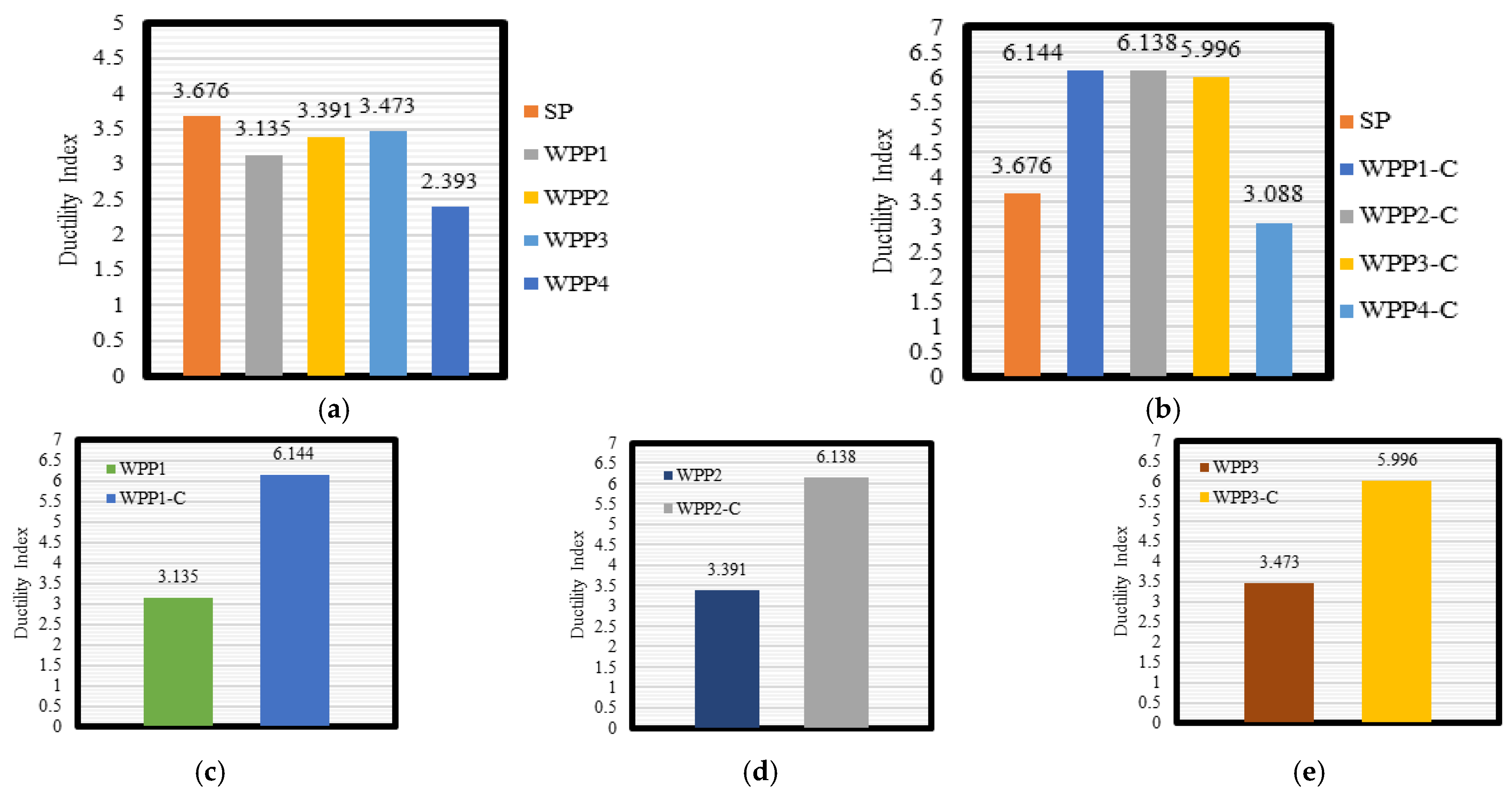
- The straight beams showed higher ductility than WPP beams, which connected the concrete parts and developed more shear stresses in the concrete design, reducing the ductility significantly. The reduction in the ductility increased with the increase in the connection zone and the concrete segment of the WPP beams, which revealed a decrement of 8–35% when the out-of-plane parts rose from two to five.
- Encasing the WPP beams with a steel box enhanced the ductility, compensating for the loss in the ductility and gaining an additional ductility of 45.3% when compared with the straight beam. Comparing the ductility index between the WPP beams with and without the steel section proved the efficiency of the steel section in improving the ductility, which showed an increment of 63–67%.
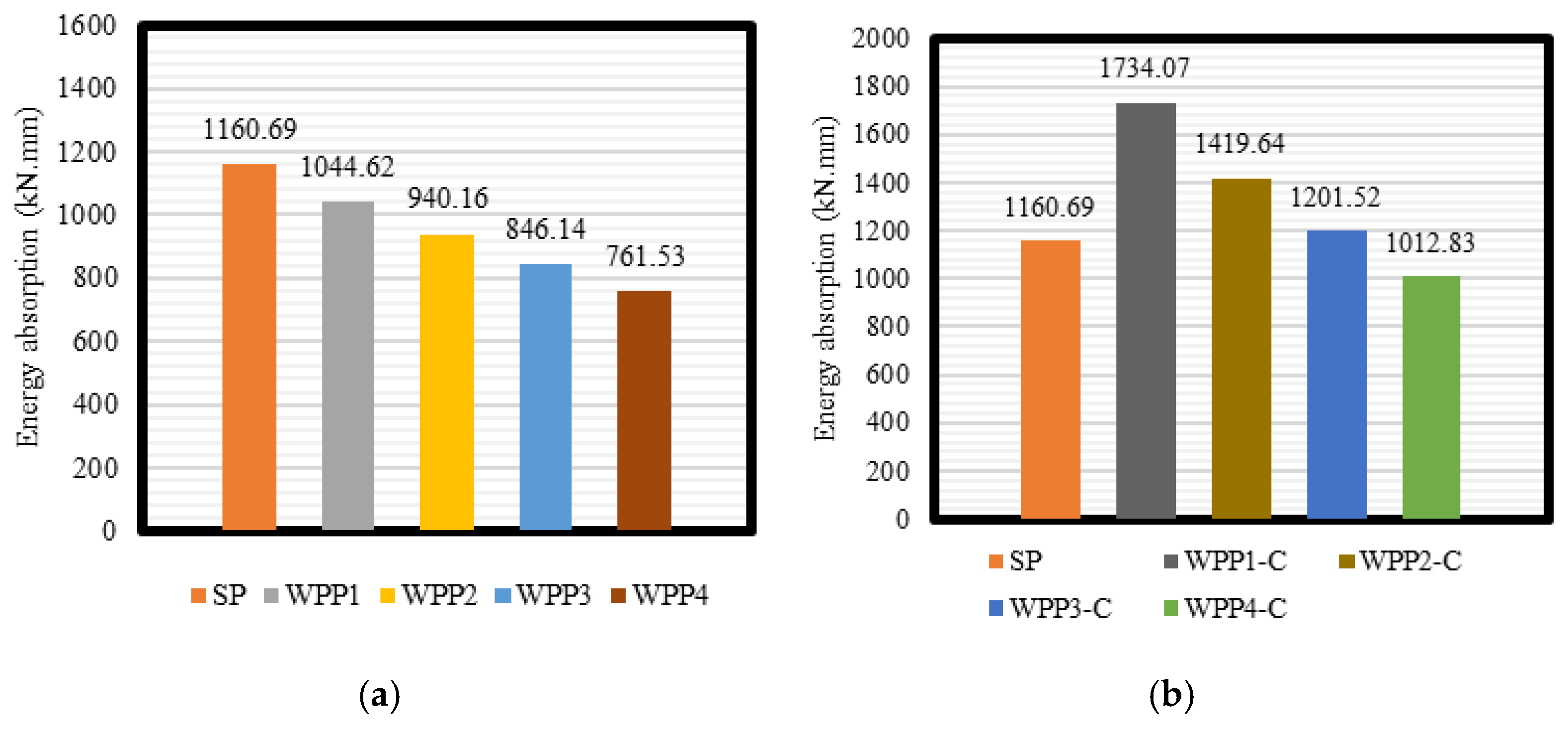
- The straight beams showed higher energy absorption than the WPP beams. In the WPP beams, the connections between the concrete parts developed more torsional and shear stresses in the concrete design. This reduction in the concrete design caused the WPP beams to have significantly reduced energy absorption compared with the straight beams.
- As the number of out-of-plane parts increased from two to five, the reduction in energy absorption increased. This increase in the out-of-plane parts and concrete segments of the WPP beams led to a 10–34.6% decrement in energy absorption. The analysis results indicated that the straight beam configuration was more favorable for maximizing energy absorption than the WPP beam design, which suffered from increased torsional and shear stresses in the concrete connections. Engineers need to carefully consider this trade-off when designing concrete beams with out-of-plane elements as the increase in these structural elements can significantly compromise the overall energy absorption capabilities of the system.
- Encasing the beams with steel boxes enhanced their energy absorption. This steel encasement compensated for the 22.6% loss in energy absorption compared with the straight beam and an additional 15.6% increase in energy absorption compared with the straight beam. Further comparisons of the energy absorption between the WPO beams with and without the steel section demonstrated the efficiency of the steel section in improving energy absorption. Including the steel section significantly increased the energy absorption, ranging from 2.2% to 49.4%.
Author Contributions
Funding
Data Availability Statement
Conflicts of Interest
References
- Arafah, A.M. Factors affecting the reliability of reinforced concrete beams. WIT Trans. Ecol. Environ. 2000, 45, 9. [Google Scholar]
- Khalel, R.I. Torsional Behavior of high-strength reinforced concrete beams. J. Eng. Sustain. Dev. 2013, 17, 317–332. [Google Scholar]
- Jagana, R.; Kumar, C.V. High strength concrete. Int. J. Eng. Sci. Res. Technol. 2017, 6, 394–407. [Google Scholar]
- Rashid, M.A.; Mansur, M.A. Reinforced high-strength concrete beams in flexure. ACI Struct. J. 2005, 102, 462. [Google Scholar]
- Ruggieri, N.; Tampone, G.; Zinno, R. In-Plane Versus Out-of-Plane “Behavior” of an Italian Timber Framed System—The Borbone Constructive System: Historical Analysis and Experimental Evaluation. Int. J. Archit. Herit. 2015, 9, 696–711. [Google Scholar] [CrossRef]
- Owainati, S.A.R. Behaviour of Reinforced Concrete Beams Under Torsion, Bending and Shear. 1973. Available online: https://spiral.imperial.ac.uk/handle/10044/1/20540 (accessed on 1 April 2024).
- Ali, M.; Anis, A. Strength and Behaviour of Reinforced Concrete Spandrel Beams. KB Thesis Scanning Project 2015. 1983. Available online: http://hdl.handle.net/1842/12664 (accessed on 1 April 2024).
- Kamiński, M.; Pawlak, W. Load capacity and stiffness of angular cross section reinforced concrete beams under torsion. Arch. Civ. Mech. Eng. 2011, 11, 885–903. [Google Scholar] [CrossRef]
- Elsayed, A.A.; Noaman, M.; Abdallah, M.A.M.; Abdelrahim, M.A.A. Behavior of R.C. beams with inclined cantilever. IOSR J. Mech. Civ. Eng. 2015, 12, 74–96. [Google Scholar]
- Rafeeq, R. Torsional Strengthening of Reinforced Concrete Beams Using CFRP Composites. Doctoral Dissertation, Portland State University, Portland, OR, USA, 2016. [Google Scholar]
- Amulu, C.P.; Ezeagu, C.A. Experimental and analytical comparison of torsion, bending moment and shear forces in reinforced concrete beams using BS 8110, euro code 2 and ACI 318 provisions. Niger. J. Technol. 2017, 36, 705–711. [Google Scholar] [CrossRef]
- Zhu, R.R.; Hsu, T.T.; Lee, J.Y. Rational shear modulus for smeared-crack analysis of reinforced concrete. Struct. J. 2001, 98, 443–450. [Google Scholar]
- Bhavikatti, S.S. Finite Element Analysis; New Age International: New Delhi, India, 2005. [Google Scholar]
- Roylance, D. Finite Element Analysis; Department of Materials Science and Engineering, Massachusetts Institute of Technology: Cambridge, MA, USA, 2001. [Google Scholar]
- Hashim, D.T.; Ahmed Albegmprli, H.M. Case study of shear strengthening of RC corbels by steel plates using FEA. East.-Eur. J. Enterp. Technol. 2023, 122, 50. [Google Scholar] [CrossRef]
- Abbu, M.A.; Ekmekyapar, T.A.; Ozakca, M.A. 3D FE modeling considering shear connectors representation and number in CBGB. Steel Compos. Struct. 2014, 17, 237–252. [Google Scholar] [CrossRef]
- Abbu, M.; Ekmekyapar, T.; Özakça, M. 3D FE modelling of composite box Girder Bridge. In Proceedings of the 2nd International Balkans Conference on Challenges of Civil Engineering, BCCCE, Tirana, Albania, 23–25 May 2013. [Google Scholar]
- Lee, J.; Fenves, G.L. Plastic-damage model for cyclic loading of concrete structures. J. Eng. Mech. 1998, 124, 892–900. [Google Scholar] [CrossRef]
- Lubliner, J.; Oliver, J.; Oller, S.; Onate, E. A plastic-damage model for concrete. Int. J. Solids Struct. 1989, 25, 299–326. [Google Scholar] [CrossRef]
- Kachlakev, D.; McCurry, D.D. Behavior of full-scale reinforced concrete beams retrofitted for shear and flexural with FRP laminates. Compos. Part B Eng. 2000, 31, 445–452. [Google Scholar] [CrossRef]
- Hashim, D.T.; Hejazi, F.; Lei, V.Y. Simplified constitutive and damage plasticity models for UHPFRC with different types of fiber. Int. J. Concr. Struct. Mater. 2020, 14, 45. [Google Scholar] [CrossRef]
- Musmar, M.A. Analysis of shear wall with openings using solid65 element. Jordan J. Civ. Eng. 2013, 7, 164–173. [Google Scholar]
- Mohsin, M.S.; Alwash, N.A.; Kadhum, M.M. Structural Behavior of reinforced concrete beams with out of plane part. Case Stud. Constr. Mater. 2021, 15, e00767. [Google Scholar] [CrossRef]
- ACI 318-19; Building Code Requirements for Structural Concrete. American Concrete Institute (ACI): Farmington Hills, MI, USA, 2019. [CrossRef]
- Mohsin, M.S.; Alwash, N.A.; Kadhum, M.M. Nonlinear Finite Element Structural Analysis of Reinforced Concrete Beams with out of Plane Parts. Math. Model. Eng. Probl. 2022, 9, 75. [Google Scholar] [CrossRef]
- Punmia, B.C.; Jain, A.K.; Jain, A.K. Reinforced Concrete Structures, Vol. 1; Laxmi Publications: New Delhi, India, 1992. [Google Scholar]
- Khamees, S.S.; Kadhum, M.M.; Alwash, N.A. Effect of hollow ratio and cross-section shape on the Behavior of hollow SIFCON columns. J. King Saud Univ. Eng. Sci. 2021, 33, 166–175. [Google Scholar] [CrossRef]
- Kim, S.B.; Yi, N.H.; Kim, H.Y.; Kim, J.H.J.; Song, Y.C. Material and structural performance evaluation of recycled PET fiber reinforced concrete. Cem. Concr. Compos. 2010, 32, 232–240. [Google Scholar] [CrossRef]
- Maghsoudi, A.A.; Bengar, H.A. Acceptable lower bound of the ductility index and serviceability state of RC continuous beams strengthened with CFRP sheets. Sci. Iran. 2011, 18, 36–44. [Google Scholar] [CrossRef]
- Park, R. Ductility evaluation from laboratory and analytical testing. In Proceedings of the 9th World Conference on Earthquake Engineering, Tokyo-Kyoto, Japan, 2–9 August 1988; Volume 8, pp. 605–616. [Google Scholar]


| Concrete type | Element | Adopted stress–strain curve |
| Concrete | SOLID65 | Multilinear stress–strain curve |
| Steel section | Membrane41 | Bilinear stress–strain curve |
| Steel rebar | LINK180 | Bilinear stress–strain curve |
| Steel plate | SOLID185 | Linear stress–strain curve |
| Beam ID | Section, mm | Overall Span, mm | Shear Span, mm | Compressive Strength, MPa | Modulus of Elasticity, GPa | Poisson’s Ratio |
|---|---|---|---|---|---|---|
| NSC-1OP | 150 × 200 | 35 | 27.6 | 0.22 | ||
| HSC-1OP | 1500 | 450 | 75 | 40.7 | 0.2 | |
| HSC-1OPT | 75 | 40.7 | 0.2 |
| Beam ID | Vu, Exp. (kN) | Vu, ANS. (kN) | ∆, Exp. (mm) | ∆, ANS. (mm) | ||
|---|---|---|---|---|---|---|
| NSC-1OP | 369.2 | 364.77 | 98.80% | 61.21 | 54.97 | 89.80% |
| HSC-1OP | 385.99 | 363.99 | 94.30% | 51.22 | 51.15 | 99.86% |
| HSC-1OPT | 460.49 | 467.40 | 101.50% | 49.62 | 48.63 | 98% |
| ID | f’c (MPa) | EC (GPa) | Plane Parts Number | Box Steel Section |
|---|---|---|---|---|
| SP | 50 | 29.60 | NSC beam with straight segment | - |
| WPP1 | 50 | 29.60 | NSC beam with two segments | - |
| WPP2 | 50 | 29.60 | NSC beam with three segments | - |
| WPP3 | 50 | 29.60 | NSC beam with four segments | - |
| WPP4 | 50 | 29.60 | NSC beam with five segments | - |
| WPP1-C | 50 | 29.60 | NSC beam with two segments | 50 × 100 mm |
| WPP2-C | 50 | 29.60 | NSC beam with three segments | 50 × 100 mm |
| WPP3-C | 50 | 29.60 | NSC beam with four segments | 50 × 100 mm |
| WPP4-C | 50 | 29.60 | NSC beam with five segments | 50 × 100 mm |
| ID | Yield Load (kN) | Yield Displacement (mm) | Failure Load (kN) | δ Corr. to | Linearity | Ductility | Energy Absorption |
|---|---|---|---|---|---|---|---|
| Pu (mm) | % | ||||||
| SP | 189.70 | 8.03 | 592.80 | 29.53 | 0.32 | 3.676 | 1160.69 |
| OPP1 | 77.97 | 10.17 | 354.40 | 31.88 | 0.22 | 3.135 | 1044.62 |
| OPP2 | 54.36 | 6.59 | 267.30 | 22.36 | 0.20 | 3.391 | 940.16 |
| OPP3 | 41.77 | 6.17 | 210.36 | 21.44 | 0.20 | 3.473 | 846.14 |
| OPP4 | 24.56 | 3.82 | 156.46 | 16.77 | 0.16 | 2.393 | 761.53 |
| OPP1-C | 146.38 | 13.94 | 563.23 | 36.98 | 0.26 | 6.144 | 1734.07 |
| OPP2-C | 118.00 | 8.63 | 496.66 | 25.04 | 0.24 | 6.138 | 1419.64 |
| OPP3-C | 105.00 | 8.38 | 428.44 | 23.58 | 0.25 | 5.696 | 1201.52 |
| OPP4-C | 74.00 | 5.24 | 366.79 | 17.91 | 0.20 | 3.088 | 1012.83 |
Disclaimer/Publisher’s Note: The statements, opinions and data contained in all publications are solely those of the individual author(s) and contributor(s) and not of MDPI and/or the editor(s). MDPI and/or the editor(s) disclaim responsibility for any injury to people or property resulting from any ideas, methods, instructions or products referred to in the content. |
© 2025 by the authors. Licensee MDPI, Basel, Switzerland. This article is an open access article distributed under the terms and conditions of the Creative Commons Attribution (CC BY) license (https://creativecommons.org/licenses/by/4.0/).
Share and Cite
Albegmprli, H.M.A.; Hashim, D.T.; Abbu, M.A.N. Combined Behavior of Reinforced Concrete Out-of-Plane Parts Beams Encased with Steel Section. Buildings 2025, 15, 2473. https://doi.org/10.3390/buildings15142473
Albegmprli HMA, Hashim DT, Abbu MAN. Combined Behavior of Reinforced Concrete Out-of-Plane Parts Beams Encased with Steel Section. Buildings. 2025; 15(14):2473. https://doi.org/10.3390/buildings15142473
Chicago/Turabian StyleAlbegmprli, Hasan M. A., Doaa T. Hashim, and Muthanna A. N. Abbu. 2025. "Combined Behavior of Reinforced Concrete Out-of-Plane Parts Beams Encased with Steel Section" Buildings 15, no. 14: 2473. https://doi.org/10.3390/buildings15142473
APA StyleAlbegmprli, H. M. A., Hashim, D. T., & Abbu, M. A. N. (2025). Combined Behavior of Reinforced Concrete Out-of-Plane Parts Beams Encased with Steel Section. Buildings, 15(14), 2473. https://doi.org/10.3390/buildings15142473