
An Investigation of the Influence of Concrete Tubular Piles at the Pit Bottom During Excavation on Bearing Behavior


Abstract
1. Introduction
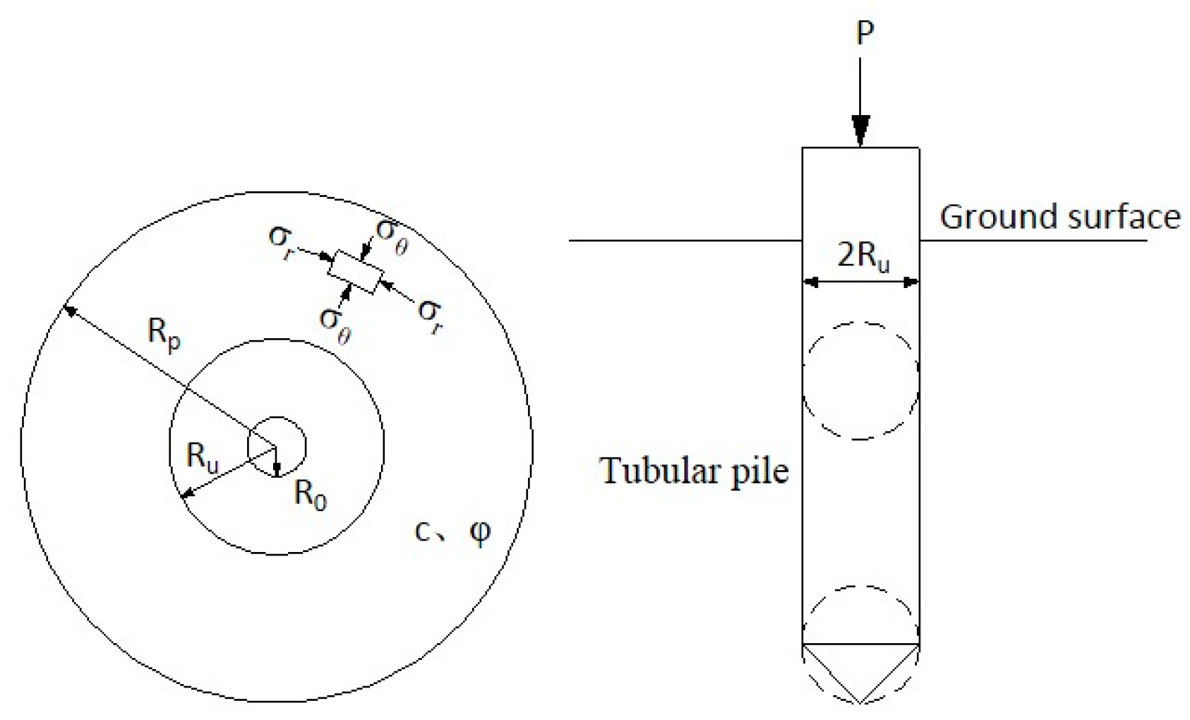
2. Driving Resistance of Tubular Piles Before Excavation
3. Effect of Excavation on Driving Resistance
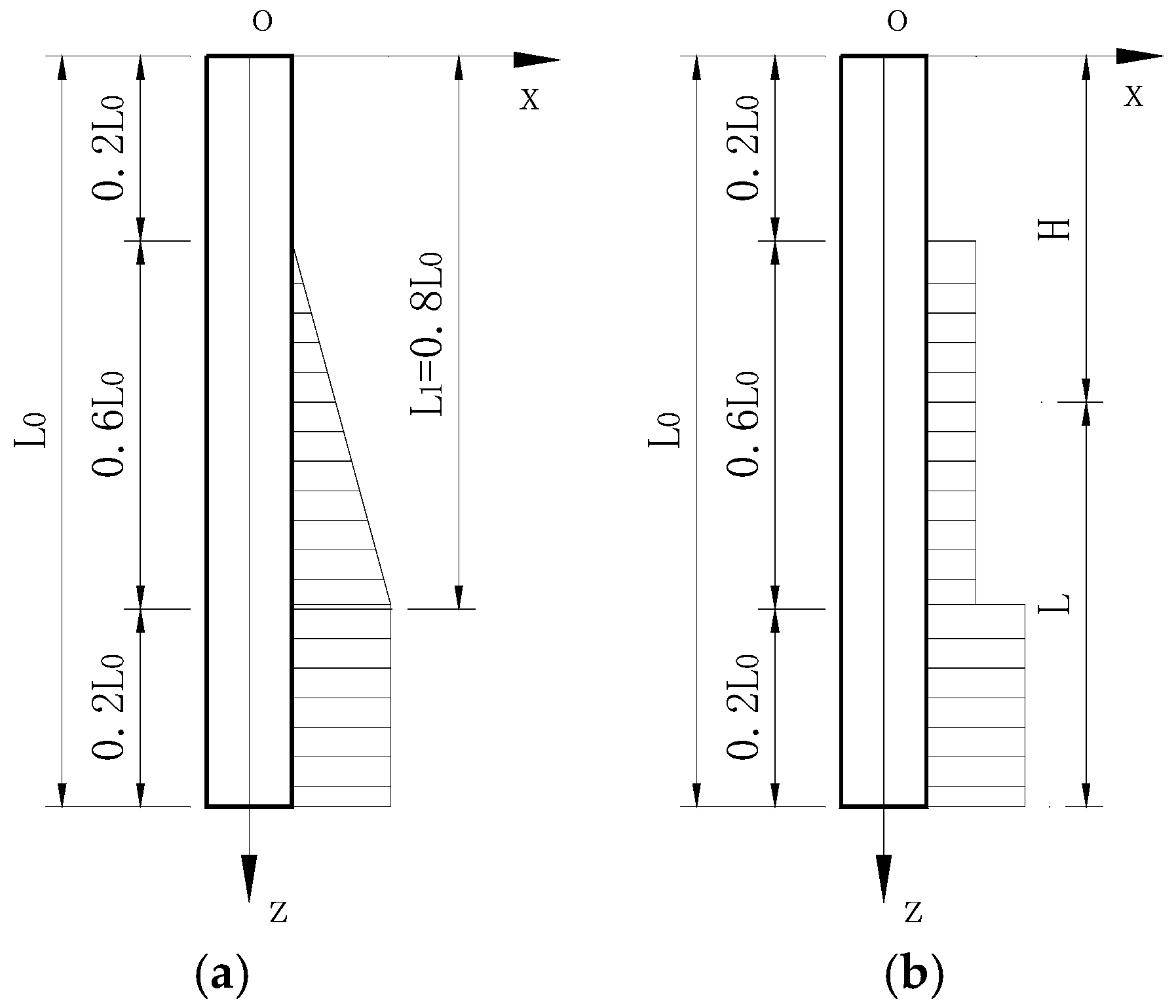
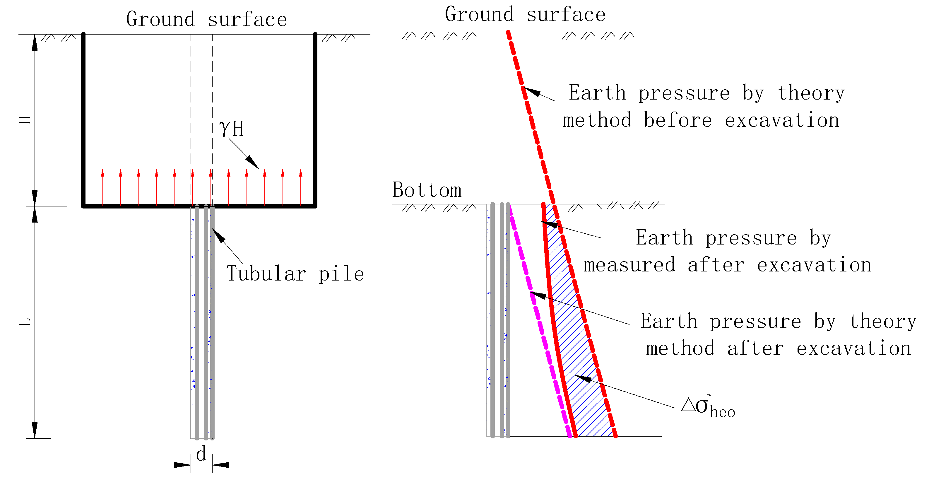
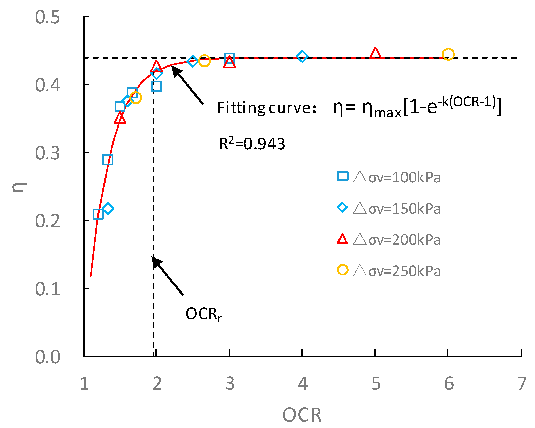
3.1. Unloading Effect at Pit Bottom
3.2. Driving Resistance and Vertical Bearing Capacity of Tubular Piles During Excavation
4. Test Results and Discussion
4.1. Case Analysis
4.1.1. Unloading Creep Test
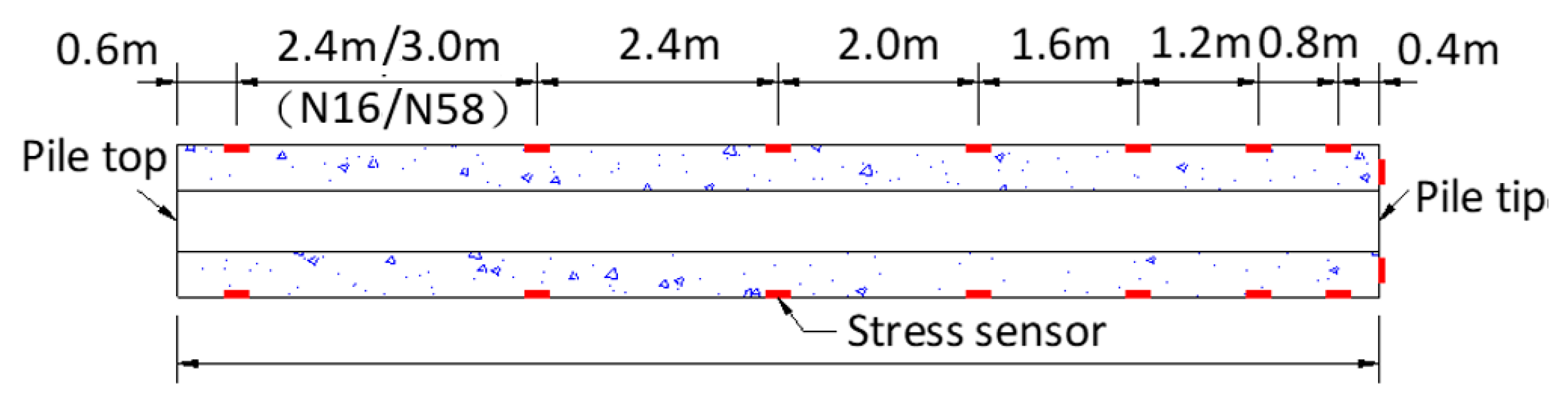
4.1.2. Field Test
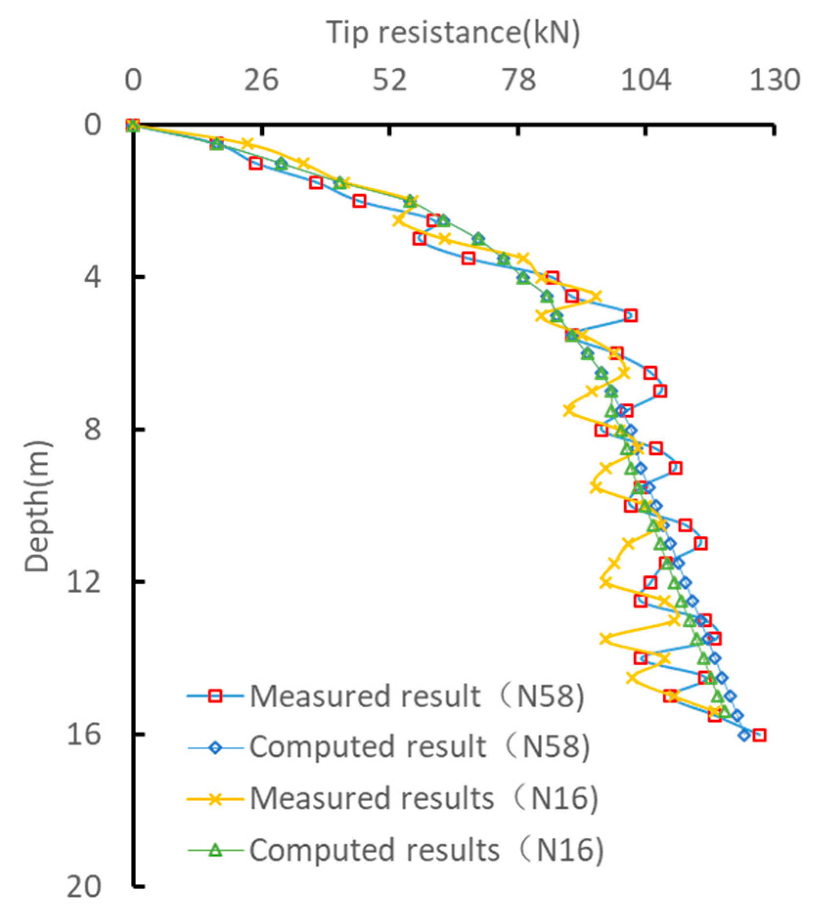
- Pile Tip Resistance
- 2.
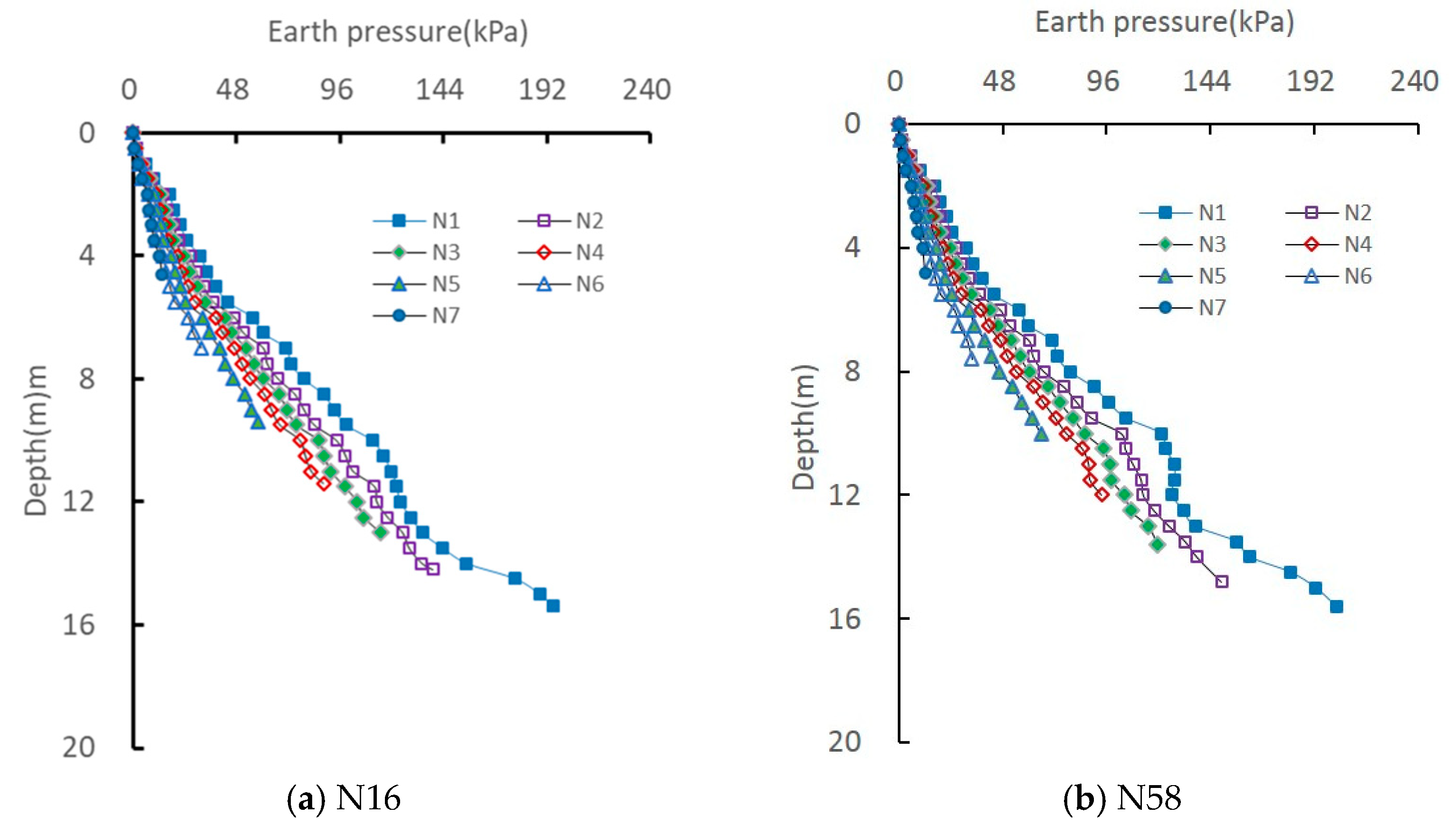
- Earth Pressure on Pile
- 3.
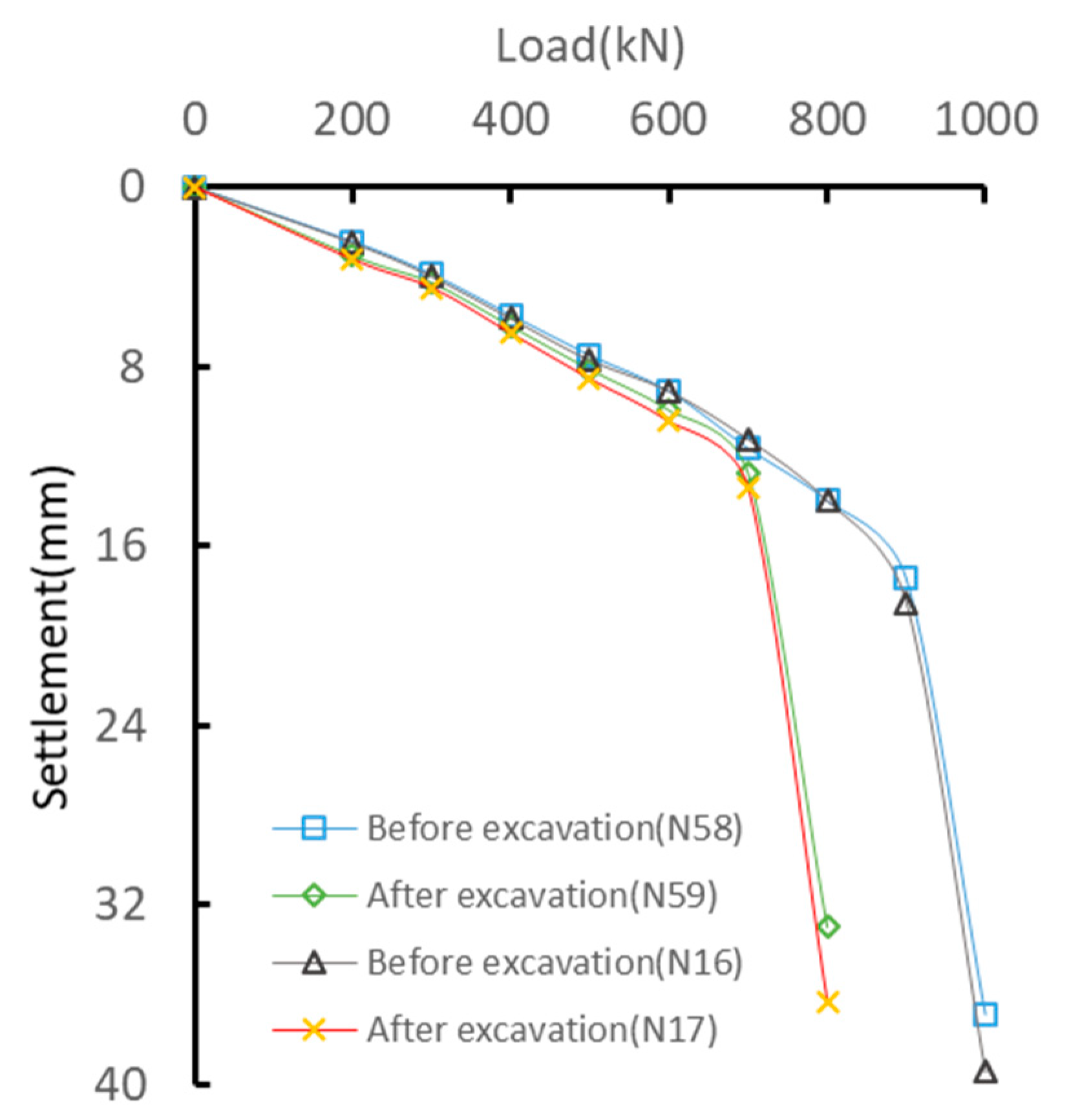
- Vertical Bearing Capacity
- 4.
- Statistical Law of Qu/Pu Ratios
4.2. Parametric Studies
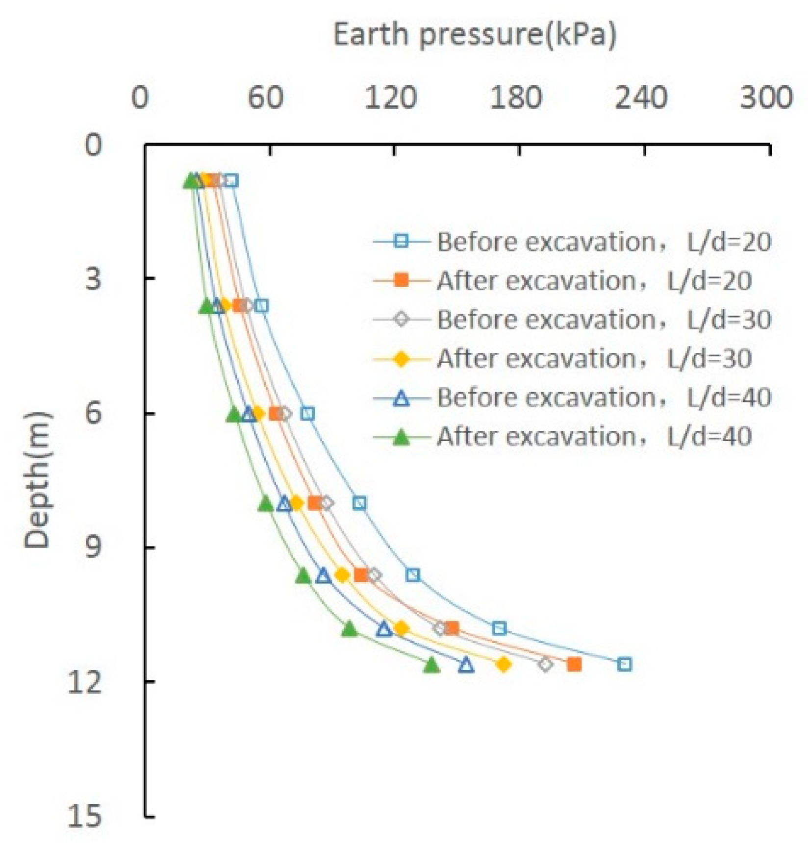
4.2.1. Effect of L/d Ratio
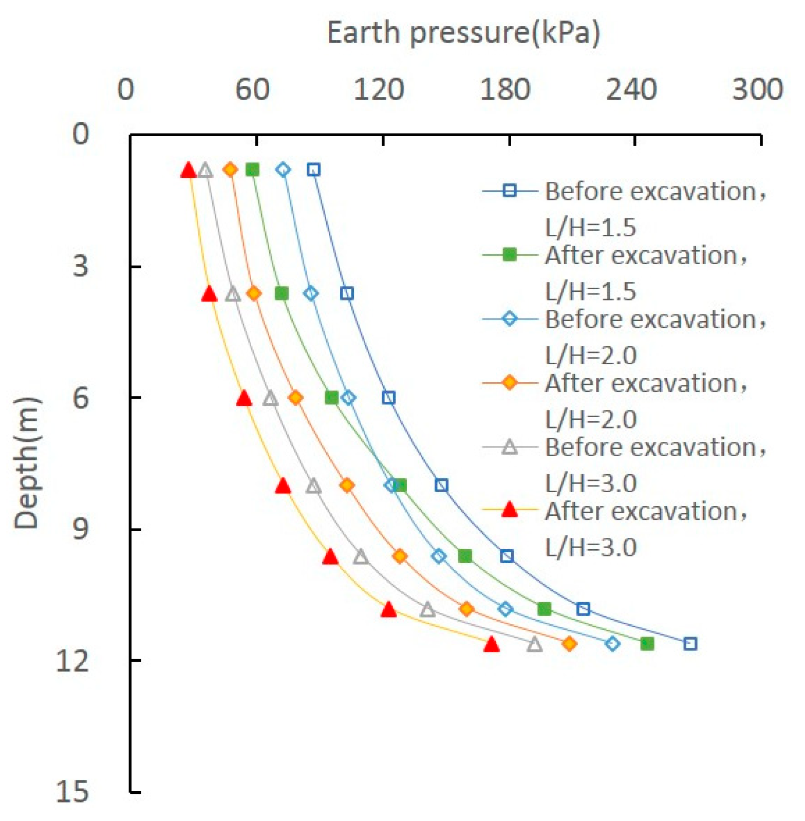
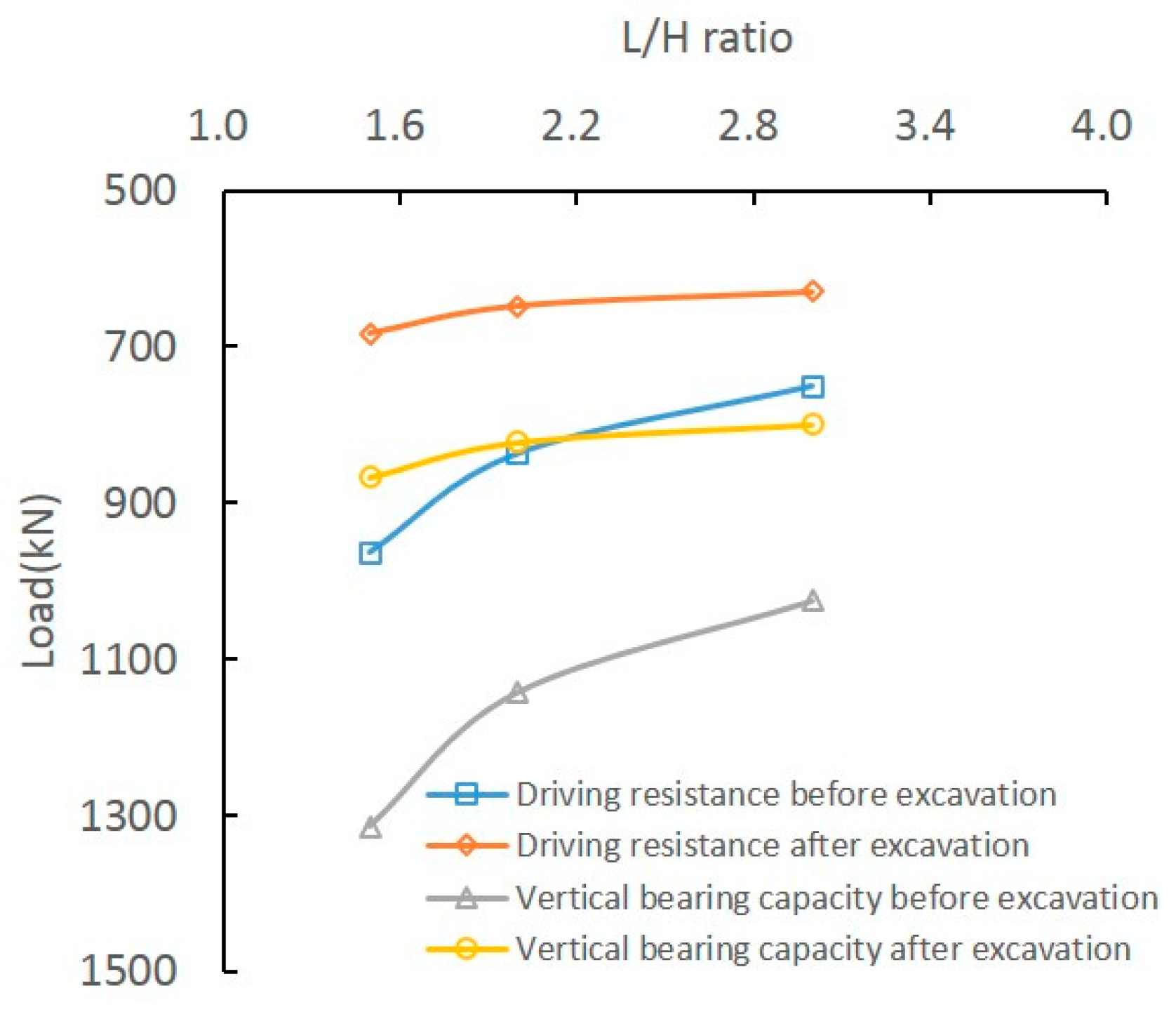
4.2.2. Effect of L/H Ratio
5. Conclusions
- (1)
- An approach to calculating the penetration resistance of the pile tip has been adopted for the driving resistance of tubular piles in foundation pits during excavation, and the results computed by using the theory method presented in this document match well with the results obtained in the field test.
- (2)
- Excavation disturbs the earth pressure acting on the pile, which significantly affects the ultimate vertical bearing capacity of the tubular pile. This confirms the adverse impact of excavation on the soil squeezing effect of tubular piles and the parameters related to pile driving resistance. Therefore, the influence of excavation on the earth pressure of tubular piles should not be ignored in design.
- (3)
- The proposed empirical method shows only 4.17% and 5.64% deviations from field test results before and after excavation. So, the proposed empirical method here is suitable for engineering design, which makes it easy to achieve the ultimate vertical bearing ability of the tubular pile as opposed to conducting tests in the field which usually cost a lot in some engineering projects.
- (4)
- Parametric analysis shows that L/d and L/H ratios significantly affect driving resistance, earth pressure, and ultimate vertical bearing capacity. Smaller L/d and L/H ratios during excavation lead to higher earth pressure and more pronounced effects on bearing capacity. Therefore, relatively large values of L/d and L/H are essential for mitigating the impact of excavation on the ultimate bearing capacity of tubular piles.
- (5)
- In this study, the parametric analysis focused exclusively on the influence of the L/d ratio and the L/H ratio on earth pressure, Qu, and Pu. Additional factors that could affect the load-bearing performance of concrete tubular piles, such as soil stratification and groundwater level, were not incorporated into the analysis. In future research, a more refined soil constitutive model will be employed, soil layering characteristics will be explicitly considered, and time-dependent effects on pile bearing behavior during excavation will be investigated to comprehensively evaluate their impacts on the load-bearing characteristics of tubular piles.
Author Contributions
Funding
Data Availability Statement
Conflicts of Interest
References
- Zhou, X.L.; Xiao, F.; Liao, H. Analysis and disposal of construction quality accidents for prestressed concrete tubular piles in soft soil areas. Ind. Constr. 2015, 45, 191–195. [Google Scholar]
- Zhang, G.; Diao, Y.; Wu, H.W. Finite element analysis on mechanism of effect of extra-deep excavation on vertical load transfer and settlement of a monopile. Chin. J. Geotech. Eng. 2009, 31, 837–845. [Google Scholar]
- Chen, J.J.; Wang, J.H.; Fan, W. Behavior of up-lift pile foundation during large-scale deep excavation. Chin. J. Geotech. Eng. 2009, 31, 402–407. [Google Scholar]
- Clough, G.W.; O’Rourke, T.D. Construction induced movements of in situ wall. Geotech. Spec. Publ. 1990, 25, 439–470. [Google Scholar]
- Hsieh, P.G.; Ou, C.Y. Shape of ground surface settlement profiles caused by excavation. Can. Geotech. J. 1998, 35, 1004–1017. [Google Scholar] [CrossRef]
- Moormann, C. Analysis of wall and ground movements due to deep excavations in soft soil based on a new worldwide database. J. Jpn. Geotech. Soc. 2008, 44, 87–98. [Google Scholar] [CrossRef]
- Leung, E.; Ng, C. Wall and ground movements associated with deep Excavations supported by cast in situ wall in mixed ground conditions. J. Geotech. Geoenviron. Eng. 2007, 133, 129–143. [Google Scholar] [CrossRef]
- Chandler, R.J. The shaft reaction of piles in cohesive soils in terms of effective stresses. Civ. Eng. Public Work. Rev. 1968, 63, 48–51. [Google Scholar]
- Mangushev, R.A.; Kolesnik, D.S. Analysis of horizontal pile displacement caused by pit excavation. J. Phys. Conf. Series 2021, 1928, 012042. [Google Scholar] [CrossRef]
- Soomro, M.A.; Mangnejo, D.A.; Bhanbhro, R.; Memon, N.A.; Memon, M.A. 3D finite element analysis of pile responses to adjacent excavation in soft ground: Effects of different excavation depths systems relative to a floating pile. Tunneling Undergr. Space Technol. 2019, 86, 138–155. [Google Scholar] [CrossRef]
- Huang, M.S.; Ren, Q.; Wang, W.D. Analysis for ultimate uplift capacity of tension piles under deep excavation. Chin. J. Geotech. Eng. 2007, 29, 1689–1695. [Google Scholar] [CrossRef]
- Zheng, G.; Diao, Y.; Ng, C.W.W. Parametric analysis of the effects of stress relief on the performance and capacity of piles in nonrelative soils. Can Geotech. J. 2011, 48, 1354–1363. [Google Scholar] [CrossRef]
- Zheng, G.; Wang, Q.; Zhang, L.M. Parametric analysis on the influence of foundation pit excavation on the performance of pit bottom piles. Build. Struct. 2015, 45, 68–74. [Google Scholar]
- Zhang, M.Y.; Deng, A.F. A spherical cavity expansion-sliding friction calculation model on the penetration of pressed-in piles. Rock Soil Mech. 2003, 24, 701–709. [Google Scholar]
- Jiang, T.; Li, B.; Yang, X.Y. Experimental study on the influence of pile driving by static pressure pile on soil near the existing pile using PIV technique. Chin. J. Undergr. Space Eng. 2018, 14, 1185–1194. [Google Scholar]
- Yang, S.C.; Zhang, M.Y.; Guan, J.P. Experimental study on the influence of excavation unloading on existing static pressure piles in silt soil. J. Shandong Agric. Univ. (Nat. Sci. Ed.) 2021, 52, 98–104. [Google Scholar]
- Yang, Q.G.; Xiao, S.; Liu, F.; Liu, X. Research on the Influence of Foundation Pit Excavation on the Vertical Bearing Characteristics of Pipe Piles. J. Hunan Univ. Technol. 2025, 39, 19–25, 78. [Google Scholar] [CrossRef]
- Vesic, A.S. Expansion of cavity in infinite soil mass. J. Soil Mech. Found. Div. Am. Soc. Civ. Eng. 1972, 98, 265–289. [Google Scholar] [CrossRef]
- Jaky, J. Pressure in soils. In Proceedings of the 2nd International conference on Soil Mechanics and Foundation Engineering, Rotterdam, The Netherlands, 21–30 June 1948. [Google Scholar]
- Chen, S.F.; Kong, L.W.; Luo, T. Lateral stress release characteristics of overconsolidated silty clay and calculation method for lateral earth pressure coefficient at rest. Rock Soil Mech. 2022, 43, 160–168. [Google Scholar] [CrossRef]
- Lin, B.H.; Wang, L. Research on bearing capacity mechanism of statically pressed precast concrete piles. J. Build. Struct. 2004, 25, 120–124. [Google Scholar] [CrossRef]


| Sample Number | Depth L (m) | Consolidation Pressure Qv (kPa) | Unloading Pressure ΔQv (kPa) |
|---|---|---|---|
| 1#−6# | 6.0 | 150, 200, 250, 300, 400, 600 | 100 |
| 7#−11# | 8.5 | 200, 250, 300, 400, 600 | 150 |
| 12#−15# | 11.0 | 250, 300, 400, 600 | 200 |
| 16#−18# | 13.0 | 300, 400, 600 | 250 |
| Soil | Thickness (m) | C (kPa) | Φ (°) | Γ (kN/m3) | Es (MPa) |
|---|---|---|---|---|---|
| fill | 0.9–3.8 | 12.6 | 8.9 | 18.7 | 4.2 |
| silty clay | 9.1–13.8 | 18.1 | 14.5 | 19.1 | 7.6 |
| weathered rock | 2.1–3.5 | 38.9 | 18.2 | 20.3 | 12.5 |
Disclaimer/Publisher’s Note: The statements, opinions and data contained in all publications are solely those of the individual author(s) and contributor(s) and not of MDPI and/or the editor(s). MDPI and/or the editor(s) disclaim responsibility for any injury to people or property resulting from any ideas, methods, instructions or products referred to in the content. |
© 2025 by the authors. Licensee MDPI, Basel, Switzerland. This article is an open access article distributed under the terms and conditions of the Creative Commons Attribution (CC BY) license (https://creativecommons.org/licenses/by/4.0/).
Share and Cite
Yang, Q.; Hong, S.; Shen, Q.; Xiao, S.; Zhu, H. An Investigation of the Influence of Concrete Tubular Piles at the Pit Bottom During Excavation on Bearing Behavior. Buildings 2025, 15, 2437. https://doi.org/10.3390/buildings15142437
Yang Q, Hong S, Shen Q, Xiao S, Zhu H. An Investigation of the Influence of Concrete Tubular Piles at the Pit Bottom During Excavation on Bearing Behavior. Buildings. 2025; 15(14):2437. https://doi.org/10.3390/buildings15142437
Chicago/Turabian StyleYang, Qingguang, Shikang Hong, Quan Shen, Sen Xiao, and Haofeng Zhu. 2025. "An Investigation of the Influence of Concrete Tubular Piles at the Pit Bottom During Excavation on Bearing Behavior" Buildings 15, no. 14: 2437. https://doi.org/10.3390/buildings15142437
APA StyleYang, Q., Hong, S., Shen, Q., Xiao, S., & Zhu, H. (2025). An Investigation of the Influence of Concrete Tubular Piles at the Pit Bottom During Excavation on Bearing Behavior. Buildings, 15(14), 2437. https://doi.org/10.3390/buildings15142437