Article

Analysis of the Mechanical Behavior of a New Stainless Steel Formwork

School of Civil & Architecture Engineering, Xi’an Technological University, Xi’an 710021, China
*
Author to whom correspondence should be addressed.
Buildings 2025, 15(14), 2394; https://doi.org/10.3390/buildings15142394
Submission received: 4 June 2025 / Revised: 2 July 2025 / Accepted: 7 July 2025 / Published: 8 July 2025
(This article belongs to the Section Building Materials, and Repair & Renovation)

Abstract

To support national goals of carbon peaking and neutrality, and to promote green, low-carbon development, this study examines the mechanical behavior and deformation characteristics of a novel stainless steel wall formwork under real-world concrete casting conditions. Field experiments were conducted on an active construction site to monitor stress distribution and displacement during concrete placement. A finite element model was established to simulate the mechanical response and validated against field data and theoretical calculations. The results show that the maximum stress and displacement occur mainly in the mid-to-lower regions of the formwork panel. The differences among numerical simulation, theoretical analysis, and field measurements were within 8%, confirming the model’s reliability. Further parametric analysis investigated the effects of varying panel thickness and rib dimensions on mechanical performance. The optimal configuration—panel thickness of 1.25 mm, horizontal ribs measuring 15 mm × 35 mm, and vertical ribs 25 mm × 9 mm—achieved a 10.32% reduction in steel usage compared to the original design, without compromising structural integrity. These findings provide a technical basis for optimizing formwork systems and contribute to resource-efficient and sustainable construction practices.

1. Introduction

China employs a variety of formwork systems—including traditional timber, steel, plastic, and aluminum—that have evolved alongside 20th-century concrete construction technologies. With the maturation of concrete technology, formwork systems have been continuously updated to balance construction quality and economic efficiency. Due to high resource consumption and limited reusability, timber formwork has gradually been replaced by alternative systems such as plastic formwork, aligning with carbon peaking and carbon neutrality goals [1]. Li et al. [2] from Shaanxi First Aluminum Formwork Technology Co, developed a novel stainless steel formwork with an optimized tie-plate slot design, which significantly reduces the use of disposable tie plates and lowers construction costs. The design further reduces the number of walers, simplifies construction procedures, and enhances construction efficiency. No release agent is required during installation, thereby reducing labor intensity. The system demonstrates high strength and stiffness, which effectively improves the quality of concrete forming. Yin et al. [3] proposed a layout scheme and an intelligent design method for pier steel formwork that adapts to dimensional changes, enabling rational parametric modeling. Zhang et al. [4] employed finite element analysis to investigate a circular ribbed steel formwork at varying casting heights, generating parameter tables that closely matched field measurements from an actual project. Xiao et al. [5] conducted casting tests on a novel channel steel column formwork system and summarized its construction process and performance. Li et al. [6] conducted monotonic static loading tests on six prefabricated steel tube concrete short columns with varying parameters, including tube thickness, rebar diameter, and diaphragm presence. Finite element analysis was also performed. The results demonstrated good structural performance and consistency in ultimate loads between experiments and simulations, validating the predictive capability of the finite element model. Luo et al. [7] analyzed the performance of a new GMT composite formwork and compared it with conventional systems. They examined development challenges and potential improvements, noting that ongoing advancements in GMT construction technology can maximize its advantages. Loureiro M.C. et al. [8] applied parametric modeling and numerical optimization to improve the geometry of steel formwork in steel–concrete composite slabs. Their findings indicated that material usage could be reduced by approximately 20% without compromising performance, while enhancing member capacity and stiffness, thereby validating the effectiveness of the optimization strategy.
This study investigates a novel stainless steel wall formwork system. On-site monitoring tests were conducted during concrete casting to measure stress variations in the panel and rib components at different stages (before, during, and after casting). The objective is to optimize the formwork design to reduce material usage and enhance economic and energy efficiency, while ensuring compliance with safety standards and design codes, thereby supporting broader application of the new stainless steel formwork.

2. Project Overview

Field monitoring tests were conducted at a construction site in Xi’an to evaluate the performance of a novel stainless steel wall formwork system during concrete casting. The standard wall formwork panel measures 2700 mm × 400 mm × 1.5 mm and is reinforced with seven transverse ribs. The cross-sectional dimensions are shown in Figure 1 and Figure 2.
The stress and displacement of the formwork were recorded at different stages—before, during, and after concrete placement. The system adopted a tie-rod configuration for both internal and external wall panels, using disposable ties installed at six heights: 200 mm, 450 mm, 1050 mm, 1650 mm, 2250 mm, and 2700 mm from the ground, with spacing not exceeding 600 mm [9]. The rear side of the formwork was reinforced with clamps and horizontal braces. Stainless steel braces, made of 50 × 50 mm square tubes, were arranged as two braces for the internal wall (at the first and fourth tie levels) and three for the external wall (at the first and fourth tie levels, and the K-plate position). Reinforcement components were also installed at the K-plate to prevent displacement, as illustrated in Figure 1. Additionally, adjustable small diagonal braces were installed just below the first tie level to prevent base displacement of the wall formwork. The spacing of these diagonal braces was based on the wall length and did not exceed 1500 mm, as shown in Figure 3.

3. Experimental Study and Analysis of Tie-Rod-Type Aluminum Formwork

3.1. Measurement Point Arrangement Test Procedure

During the on-site concrete pouring tests, the new stainless steel formwork panel located at the center of the wall was instrumented [10,11,12]. The displacement sensor is connected at one end to the formwork and at the other end to the strain measurement device. Measurement points were arranged on the upper, middle, and lower sections of the panel, as well as on the adjacent horizontal and vertical ribs, as shown in Figure 2. In the figure, the black lines indicate the joint locations between two formwork panels. Strain gauges were labeled MB1–MB4 on the panel, HL5–HL8 on the horizontal ribs, and ZL9–ZL12 on the vertical ribs (see Figure 4). A total of 22 strain measurement points and 16 displacement transducers were installed on the formwork. The experimental procedure is illustrated in Figure 5, Figure 6 and Figure 7.

3.2. Test Procedure

The test was divided into three stages—before, during, and after concrete pouring—based on the stress characteristics of the formwork [13]. After the displacement transducers and strain gauges were installed, the formwork was already bearing its self-weight, which had a negligible effect on the measurements. The test aimed to monitor stress and displacement variations in the formwork during concrete pouring, while ensuring all sensors remained fully operational [14,15,16]. A total of 22 strain gauges and 16 displacement transducers were deployed.

3.3. Results and Analysis

Building on the experimental results, this study investigates the stress and displacement behavior of the panels, horizontal ribs, and vertical ribs of the novel stainless steel formwork in wall applications. Field monitoring data were systematically organized and analyzed using Origin 2024 software to generate time–stress and time–displacement curves for each measurement point on the wall panels, facilitating further analysis and improving the understanding of their mechanical performance. Stress and displacement curves were obtained for the panels, horizontal ribs, vertical ribs, walers, and tie rods.

3.3.1. Stress Measurement and Analysis of Critical Components

1.
Panel Stress Analysis
During concrete pouring, the stress in the wall formwork panel initially increased rapidly at all measurement points. As the pouring height increased, the lateral pressure on the formwork rose, causing the rate of stress increase to slow. After pouring was completed, the heat of hydration from the concrete led to shrinkage, resulting in a gradual decrease and eventual stabilization of stress. A transient spike in stress was observed during the vibration phase due to a momentary local increase in lateral pressure, with the maximum value of 37.37 MPa occurring at point MB-3. The peak stresses at the four measured points were 27.82 MPa, 37.37 MPa, 26.24 MPa, and 21.86 MPa, all well below the allowable code limits. These results are illustrated in Figure 8.
2.
Horizontal Rib Stress Analysis
Prior to concrete pouring, the stress in the horizontal ribs of the wall formwork gradually increased, primarily due to live loads generated by construction activities. During concrete pouring, stress at all measurement points continued to increase. After pouring was completed, the maximum stresses recorded at the horizontal ribs were 32.68 MPa, 44.36 MPa, 56.64 MPa, and 48.64 MPa, with the peak value of 56.64 MPa occurring at point HL-7. These results are illustrated in Figure 9.
3.
Vertical Rib Stress Analysis
During the test, the stress in the vertical ribs of the wall formwork increased gradually at the start of concrete pouring, followed by a phase of accelerated growth. As the pouring height increased, the stress at each measurement point began to decline. After the pouring was completed, the stress at all points gradually decreased and eventually stabilized. The maximum recorded stresses were 85.10 MPa, 69.90 MPa, 67.57 MPa, and 102.47 MPa, with the highest value observed at point ZL-12 (102.47 MPa). These results are illustrated in Figure 10.

3.3.2. Displacement Measurement and Analysis of Critical Components

1.
Displacement Analysis of the Panel
During the test, the displacement at all wall panel measurement points increased gradually due to live loads before concrete pouring. As pouring commenced, displacements at the monitored points increased to varying degrees. The maximum displacement was observed at point MB-3, reaching 0.17 mm, while the other two points reached 0.10 mm and 0.15 mm, respectively, approximately five hours into the process. After the completion of pouring, as the concrete set and the live loads were removed, the displacements at all points gradually decreased and eventually stabilized. These results are illustrated in Figure 11.
2.
Displacement Analysis of the Horizontal Ribs
During the test, the horizontal ribs showed distinct displacement patterns. Point HL-6, positioned on the lower panel, exhibited the largest displacement of 0.23 mm, followed by HL-5 (0.17 mm) and HL-4 (0.11 mm). The significantly greater displacements at HL-6 and HL-5 compared to HL-4 indicate that the lower ribs experienced higher lateral pressure during concrete pouring. After reaching peak values, the displacements at all points gradually decreased and stabilized following the removal of construction live loads. These results are illustrated in Figure 12.
3.
Displacement Analysis of the Vertical Ribs
During the test, the displacement of the vertical ribs gradually increased at the onset of concrete pouring, showing consistent trends across all measurement points. After five hours, the maximum displacements at points ZL-7, ZL-8, and ZL-9 reached 0.13 mm, 0.17 mm, and 0.19 mm, respectively, with ZL-8 and ZL-9 showing similar values. After pouring was completed and live construction loads were removed, the displacements at all points gradually decreased and stabilized. These findings indicate that the novel stainless steel formwork exhibits excellent mechanical strength and structural stability. The displacement variations are shown in Figure 13.

4. Theoretical Calculation

4.1. Design Calculation Method

In accordance with the Chinese standard “Technical Code for Safety of Building Formwork”(JGJ 162-2008) [17], the bending stress of the novel stainless steel wall formwork is determined using Equations (1)–(4).
y ̅ = A i y i A i
I = I i + A i y i y ̅ 2
W = I y m a x
σ = M m a x W     f a
In the formulas,
A i —the area of each sub-section;
y i —the vertical distance from the base to the centroid of each sub-section;
I i —the local moment of inertia of each rectangle about its own centroid,   I i = 1 12 b i h i 3 ;
y m a x —the distance from the neutral axis to the farthest edge of the section;
σ —the design value of bending strength;
f a —the design value of the bending strength of the steel;
W —the section modulus of the effective net cross-section of the primary profile about the bending axis.
M m a x —the design value of the most unfavorable bending moment, which is taken as the greater of the calculated results under uniform load and concentrated load; the deflection of the formwork calculated under the standard value of permanent load;
The deflection of the stainless steel formwork panel is evaluated using a simply supported beam model, as described by Equation (5).
a f G = 5 q G L 4 384 E α I x a f , l i m
In the formula,
a f G —the deflection of the formwork calculated under the standard value of permanent load;
q G —the standard value of the uniformly distributed load;
E α —the elastic modulus of the steel;
I x —the moment of inertia of the effective net cross-section of the primary profile about the bending axis, selected based on the actual loading condition;
a f , l i m —the allowable deflection limit for the formwork.
The code provides textual descriptions of the panel, horizontal ribs, and vertical ribs but does not specify explicit calculation formulas. Therefore, to evaluate the bearing capacity and deformation, the actual structure must be simplified into a suitable analytical model.

4.2. Load Calculation

The mechanical performance of the new stainless steel wall formwork is assessed by estimating the maximum lateral pressure generated during concrete pouring. In accordance with the Chinese standard GB 50666-2011 [18] for concrete structures, the maximum standard lateral pressure on the formwork under internal vibration can be calculated using the following equations, as shown in Formulas (6) and (7).
F k = 0.28 γ c t 0 β v
F k = γ c H
In the formula,
F k —the standard value of the maximum lateral pressure exerted by freshly poured concrete on the side of the formwork ( k N / m 2 );
γ c —the unit weight of concrete ( k N / m 3 );
t 0 —the initial setting time of the freshly poured concrete ( h ), determined by actual measurements (°C);
β —the correction factor accounting for the influence of concrete slump;
v —the concrete pouring rate ( m / h );
H —the vertical distance from the point of interest to the top surface of the freshly poured concrete ( m ).
The standard lateral pressures calculated using the two formulas were 33.6 k N / m 2 and a higher value. For design purposes, the lower value of 33.6 k N / m 2 was adopted. By including a horizontal correction component of 4.0 k N / m 2 , the final design lateral pressure was determined to be 49.68 k N / m 2 .

4.3. Simplified Theoretical Calculation for Formwork Components

The standard wall formwork panel measures 2700 mm × 400 mm × 1.5 mm and is reinforced with seven transverse ribs.

4.3.1. Simplified Structural Analysis of the Formwork Panel

The calculation model for the novel stainless steel formwork panel is simplified as a continuous beam supported by the frame and vertical ribs [19]. Since the panel and the end ribs are fabricated as a single integrated component, the two ends are modeled as fixed supports. The span L was determined based on the limits prescribed in the Technical Code for Safety of Construction Formwork (JGJ 162-2008), which provides standardized guidelines for structural design parameters. The simplified schematic is illustrated in Figure 14.
The section modulus of the panel is w = 1473   m m 3 . The panel is modeled as a three-span continuous beam for structural analysis. The corresponding formulas for strength and deflection are provided in Equations (8)–(10).
M = a m × q l 01 4
B C = E h 3 12 ( 1 v 2 )
d = a d × q l 01 4 B C
In the formula,
l 01 —the smaller value between the two edge lengths ( l x and l y ) of the biaxial panel;
q —the uniformly distributed load applied to the panel ( k N / m 2 );
E —the elastic modulus of the steel (MPa);
h —the thickness of the biaxial panel ( m m );
v —the Poisson’s ratio of the material;
α m —the bending moment coefficient;
α d —the deflection coefficient.
The uniform load applied to the panel is given as follows:
q 1 = q × l = 49.68 × 10 3 × 400 = 19.87   N / m m
The panel was modeled as a 400   m m × 400   m m square plate with four fixed edges. Based on the coefficient table for fully fixed plates, when l x / l v = 350 / 400 = 0.9 , the corresponding values are f = 0.00127 ,   m = 0.0176 . Substituting these into Equations (5)–(7) yields a maximum bending stress of 36.67   M p a and a maximum deflection of 1.4   m m .

4.3.2. Simplified Calculation of Horizontal Ribs

The horizontal ribs of the formwork are idealized as single-span beams with fixed ends, subjected to concentrated loads transferred from the vertical ribs. The back braces are treated as simply supported members at fixed intervals. The simplified calculation model is illustrated in Figure 15.
The load calculation width for the horizontal rib is taken as 400   m m . The section modulus is denoted as W 1 = 7451   m m 3 , and the moment of inertia is I 1 = 164 , 530   m m 4
The line load acting on the horizontal rib is given as follows:
q 2 = q × b = 49.68 × 10 3 × 400 = 19.87   N / m m
The maximum bending moment of the horizontal rib is calculated as follows:
M m a x = q 2 l 2 8 = 19.87 × 400 2 8 = 397,400   N · m m
The maximum stress in the horizontal rib is calculated as follows:
σ = M m a x W 1 = 397,400 7451 = 52.55   N / m m 2     f a = 200   N / m m 2
The maximum deflection of the horizontal rib is calculated as follows:
a f G = 5 q 2 L 4 384 E I = 5 × 19.87 × 400 4 384 × 70,000 × 164,530 = 0.57   m m 1.5   m m

4.3.3. Simplified Calculation of Longitudinal Ribs

The longitudinal ribs of the novel stainless steel formwork are simplified as a continuous beam system. In this model, the side frames are treated as fixed supports, while the intermediate transverse ribs serve as elastic supports. This configuration reflects the actual mechanical boundary conditions of the formwork system and enables a more accurate analysis of stress distribution and deflection. The simplified calculation model is illustrated in Figure 16.
The longitudinal ribs of the new stainless steel wall formwork are designed with a span of 900 mm. The section modulus and moment of inertia of the transverse ribs are W 2 = 9080   m m 3 and I 2 = 284,980   m m 4 , respectively.
The design load acting on the longitudinal rib is given as follows:
q 3 = q × a = 49.68 × 10 3 × 0.133 = 6.61   N / m m
The maximum bending moment of the longitudinal rib is as follows:
M m a x = q 3 l 2 8 = 6.61 × 900 2 8 = 669,262.5   N · m m
The maximum stress in the longitudinal rib is as follows:
σ = M m a x W 2 = 66,926.5 9080 = 73.7   N m m 2 f a = 200   N / m m 2
The maximum deflection of the longitudinal rib is as follows:
a f G = 5 q 3 L 4 384 E I = 5 × 6.61 × 900 4 384 × 70,000 × 284,980 = 2.8   m m     3.6   m m

4.4. Comparison of Test Results and Theoretical Calculations

Theoretical calculations were compared with on-site experimental results, revealing that the maximum stress and displacement measured during concrete pouring were lower than the theoretical values. These results satisfy the relevant code requirements, as shown in Table 1.

5. Numerical Simulation

5.1. Finite Element Modeling

Midas Gen was employed for the finite element analysis of the new stainless steel wall formwork with standard dimensions of 2700 mm in length, 400 mm in width, and 1.5 mm in thickness. Given the large ratio of length to thickness, the formwork was modeled as a thin plate structure. A uniform surface load of 49.68   k N / m 2 was applied to simulate the concrete pressure during casting.
The finite element model was constructed with a mesh size of 30 mm [20]. (All of these parameters were employed for the purpose of finite element analysis.) Boundary conditions were defined by applying fixed supports at both ends to simulate frame constraints, while additional constraints were applied on the transverse ribs. Figure 17 shows the geometric model of the formwork. The mesh division is illustrated in Figure 18. Figure 19 presents the boundary condition settings, and the load distribution is shown in Figure 20.
Table 2 presents the material properties of the novel stainless steel formwork.

5.2. Calculation Results and Analysis

5.2.1. Finite Element Analysis of the PanelRib Finite Element Analysis

The analysis results indicate that the upper part of the panel experiences relatively low stress, while the middle and lower sections of the wall formwork are subjected to higher stress. The maximum stress in the wall formwork reaches 35.68 MPa, as shown in Figure 21. The maximum displacement, 0.21 mm, occurs below the center of the eighth transverse rib, due to fixed supports at both ends and hinged constraints at the transverse ribs, combined with the greatest lateral concrete pressure at the bottom; the lowest wall formwork panel exhibits the maximum displacement. The relevant information has been supplemented and is presented in Figure 22.
The finite element analysis (FEA) results of the new stainless steel wall formwork panel closely align with the on-site experimental monitoring values, with only a 5.2% difference. Both the numerical and experimental stress values are considerably lower than the material’s design strength, indicating an adequate safety margin and compliance with relevant standards. This consistency confirms the reliability of the FEA in simulating the structural behavior of the formwork system. Detailed comparison data are presented in Table 3.

5.2.2. Rib Finite Element Analysis

The finite element model results indicate that the mid- and lower portions of the transverse ribs experience higher stress levels than the upper portion, suggesting a non-uniform distribution of lateral pressure along the wall formwork. The maximum stress, measured at the second rib from the bottom, reached 56.64 MPa, as shown in Figure 23. The displacement distribution of the transverse ribs follows a similar pattern to the stress distribution, further confirming that the lateral concrete pressure is greater in the middle and lower regions than in the upper part. The maximum displacement occurred at the second rib from the top, as illustrated in Figure 24.
The measured stress of the transverse ribs during in situ concrete pouring is lower than the results obtained from the finite element analysis (FEA). This is primarily due to the more comprehensive boundary and loading conditions considered in the FEA model to enhance its accuracy. Despite this, the calculated maximum stress complies with design code requirements and maintains a significant safety margin. The measured displacement is 4.1% lower than the FEA result and remains within the acceptable range, further validating the accuracy of the simulation. These results are summarized in Table 4.

5.2.3. Finite Element Analysis of Longitudinal Ribs

The analysis results show that the stress in the longitudinal ribs gradually increases from top to bottom. The maximum stress, 102.47 MPa, occurs at the center of the intersection between the second panel from the bottom and the longitudinal rib, as shown in Figure 25. The maximum displacement of the longitudinal rib is 0.17 mm, located at the midsection of the lower longitudinal rib, as illustrated in Figure 26.
The finite element analysis (FEA) results for the longitudinal ribs of the stainless steel wall formwork closely align with the values obtained from on-site testing. Specifically, the FEA stress results are 4.1% higher than the measured values, and the displacement values from the on-site monitoring are 6.3% higher than those calculated by the FEA. Both sets of results conform to the relevant code requirements, thereby verifying the accuracy and reliability of the simulation. The detailed comparison is presented in Table 5.

5.3. Comparative Analysis of Numerical Results

Based on a comparative analysis between theoretical calculations and finite element analysis (FEA) results for the formwork components, it was found that the FEA results are generally higher. For instance, using the novel stainless steel formwork as an example, the theoretical maximum stress and deflection of the faceplate were 36.67 MPa and 1.4 mm, respectively, while the FEA yielded 35.68 MPa and 0.21 mm. The slightly larger theoretical values may be attributed to differences in loading conditions—actual conditions rarely achieve the most unfavorable load—and to methodological differences, as theoretical analysis relies on simplified assumptions, whereas FEA considers more comprehensive factor interactions. For the transverse and longitudinal ribs, theoretical stresses were 52.55 MPa and 73.71 MPa, and deflections were 0.57 mm and 2.8 mm, respectively. In contrast, the FEA results showed higher values of 59.63 MPa and 106.66 MPa for stress. This increase can be explained by more complex modeling assumptions and more accurate consideration of nonlinear and anisotropic material properties in FEA. The detailed comparison results are presented in Table 6.

6. Design Optimization

Finite element analyses were conducted on wall formworks with varying dimensions by systematically altering the panel thickness, transverse rib height and width, and longitudinal rib height and width of the new stainless steel formwork.
Taking the original panel thickness of 1.50 mm as a reference, this study investigates structural responses under five alternative thicknesses: 1.00 mm, 1.25 mm, 1.75 mm, 2.00 mm, and 2.25 mm. The results indicate that both the maximum equivalent stress and maximum displacement decrease progressively with increasing panel thickness. When the panel thickness is 1.00 mm, the structure exhibits the most pronounced response, with a maximum equivalent stress of 196.4 MPa and a displacement of 1.21 mm. Although it satisfies the code requirements, the safety margin is insufficient, and this thickness is therefore not recommended. Increasing the thickness to 1.25 mm results in the largest reductions in stress and displacement, by 23.98% and 46.28%, respectively. The corresponding maximum stress and displacement are 36.43% and 43.33% of the material strength and allowable displacement limit, respectively, indicating a substantial improvement in structural safety. Further increasing the thickness to 2.25 mm yields continued improvement in the structural response; however, the benefits become marginal, indicating diminishing returns. Therefore, a panel thickness of 1.25 mm is recommended as the optimal choice, considering structural performance, safety margins, and material utilization. The trends of stress and displacement with respect to panel thickness are illustrated in Figure 27.
Using the original rib width of 20 mm as a baseline, this study analyzes five alternative rib widths: 10 mm, 15 mm, 25 mm, 30 mm, and 35 mm. Results indicate that rib width significantly affects the structural performance of the formwork system. At a rib width of 10 mm, the maximum equivalent stress and displacement meet code requirements but offer a limited safety margin. Increasing the width to 15 mm results in the greatest reductions in stress and displacement, by 16% and 26%, respectively. This improvement enhances structural performance and facilitates lightweight design of the formwork components. Considering both strength control and weight reduction, a rib width of 15 mm is recommended as the optimal choice. The trends of stress and displacement are presented in Figure 28.
To achieve a lightweight design of the novel stainless steel formwork, this study analyzes the structural performance of wall panels with rib heights of 30 mm, 35 mm, 40 mm, 45 mm, 50 mm, and 55 mm, using the original height of 45 mm as a reference. Results indicate that rib height significantly affects the equivalent stress and displacement of the structure. Increasing the rib height from 30 mm to 35 mm yields the most pronounced improvement, with maximum equivalent stress decreasing by 13.73% to 158.38 MPa and maximum displacement reducing by 25.14% to 0.65 mm. Further increasing the rib height to 55 mm results in marginal performance gains, indicating diminishing returns. Considering both structural performance and cost efficiency, a rib height of 35 mm is recommended as optimal. The trends of stress and displacement are illustrated in Figure 29.
As the primary component resisting lateral pressure in the formwork system, the longitudinal rib has a significant influence on structural performance, with different widths leading to varying stress and displacement responses. Using the original rib width of 30 mm as a reference, the maximum displacement was reduced by 14.49%. To evaluate the effect of rib width on wall panel behavior, five configurations—20 mm, 25 mm, 30 mm, 35 mm, and 40 mm—were analyzed. The most notable improvement occurred when the width increased from 20 mm to 25 mm, resulting in an 11.95% reduction in maximum stress and a corresponding decrease in displacement. Beyond 25 mm, further increases in width produced only marginal performance gains. Therefore, a rib width of 25 mm is recommended to achieve an optimal balance between structural efficiency and lightweight design. Stress and displacement trends are illustrated in Figure 30.
Using the original longitudinal rib height of 10 mm as a reference, six rib heights (7 mm, 8 mm, 9 mm, 10 mm, 11 mm, and 12 mm) were analyzed to evaluate their influence on the structural performance of stainless steel wall formwork. Results indicate that all configurations meet the relevant design specifications in terms of maximum stress and displacement. However, at a height of 7 mm, the maximum stress reached 114.82 MPa and the maximum displacement was 0.94 mm, accounting for 62.67% of the allowable displacement limit. Such excessive deformation may pose a risk of irreversible damage in practical applications. Increasing the rib height from 7 mm to 9 mm resulted in a notable decrease in both stress (by 19.43%) and displacement (by 17.11%). Beyond 9 mm, further increases yielded only marginal improvements, indicating diminishing returns. Therefore, considering both structural performance and material efficiency, a rib height of 8 mm or 9 mm is recommended as the optimal choice. Stress and displacement trends are illustrated in Figure 31.
Three design schemes were selected, and their parameters are listed in Table 7. A comparative analysis was then conducted to determine the optimal scheme.

Comparison of Design Schemes

Finite element analysis was conducted using MIDAS GEN under a uniform load of 49.68 k N / m 2 . The resulting stress and displacement contour plots are shown in Figure 32 and Figure 33, respectively.
Under the constraints of stiffness and load-bearing capacity, the optimized stainless steel wall formwork exhibits improved economic efficiency. Scheme 1 meets the requirements for stiffness and load-bearing capacity while balancing structural safety and economic efficiency. Its maximum displacement is well controlled within a reasonable range, providing a good safety margin. Although its optimization rate is slightly lower than that of Scheme 2, it offers better deformation control without increasing construction complexity. In contrast, Scheme 3 further reduces deformation, but the improvement is limited and not cost-effective. Overall, Scheme 1 achieves the optimal balance among safety, cost-effectiveness, and on-site applicability, and is therefore considered the most favorable design solution. The design parameters of each scheme are listed in Table 8.

7. Conclusions

This study, based on an ongoing construction project in Xi’an, investigates a novel stainless steel wall formwork through systematic analysis of its panels, transverse ribs, and longitudinal ribs using finite element analysis, theoretical calculations, and field test monitoring. A comparison among experimental results, theoretical values, and finite element simulations confirms the accuracy and reliability of the finite element method. Furthermore, the structural parameters of the formwork were optimized using MIDAS GEN 2023 software, and relevant conclusions were accordingly drawn.
A comparative analysis was conducted between the theoretical values and the field test results of the novel stainless steel wall formwork. The experimental data were obtained from 22 stress measurement points and 16 displacement measurement points selected during the monitoring process. Throughout the concrete pouring stage, the longitudinal ribs of the formwork were subjected to the highest stresses. The maximum measured stresses of the panel, transverse ribs, and longitudinal ribs were 37.37 MPa, 56.64 MPa, and 102.47 MPa, respectively, while the corresponding theoretical values were 36.67 MPa, 52.55 MPa, and 73.71 MPa. All measured stress values were within the allowable range and showed reasonable agreement with the theoretical predictions. In addition, the measured displacements of all components were lower than the theoretical values, indicating that the structural performance meets the relevant code requirements.
Finite element analysis indicated that the formwork remained under low stress and experienced minimal displacement, meeting relevant code requirements. A comparison among FEA results, theoretical calculations, and field test data revealed a maximum deviation of no more than 8%, confirming the accuracy and reliability of the simulation results.
By adjusting the panel thickness as well as the width and height of both transverse and longitudinal ribs, the influence of different parameters on the load-bearing capacity and deformation of the wall formwork was examined. The optimal design was determined to consist of a 1.25 mm panel thickness, 15 mm wide and 35 mm high transverse ribs, and 25 mm wide and 9 mm high longitudinal ribs, achieving a 10.32% reduction in steel usage compared to the original configuration.

Author Contributions

Conceptualization, F.Z., S.Y. and K.G.; Data curation, F.Z. and S.Y.; Formal analysis, Q.X.; Funding acquisition, F.Z.; Investigation, Q.X. and K.G.; Methodology, F.Z.; Project administration, F.Z.; Resources, F.Z.; Software, F.Z.; Supervision, F.Z.; Validation, Q.X.; Visualization, Q.X. and K.G.; Writing—original draft, F.Z., S.Y. and Q.X.; Writing—review and editing, F.Z., S.Y. and K.G. All authors have read and agreed to the published version of the manuscript.
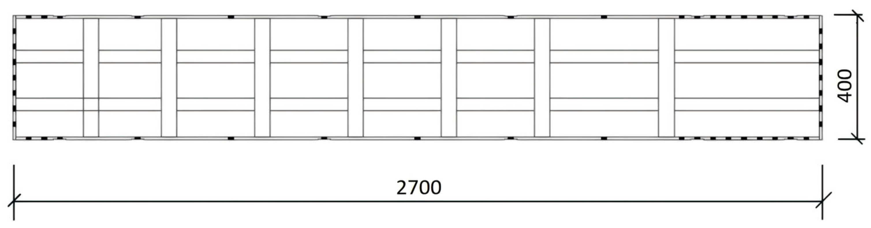
Funding

The work was financially supported by the Shaanxi Key Research and Development Program (2023JBGS-17) and the Shaanxi Key Research and Development Program (2024SF2-GJHX-63).

Data Availability Statement

The raw data supporting the conclusions of this article will be made available by the authors on request.

Conflicts of Interest

The authors declare that they have no conflicts of interest.

References

  1. Duan, D. Mechanical Behavior and Rib Form Optimization of New Aluminum Alloy Formwork. Master’s Thesis, Dalian University of Technology, Dalian, China, 2019. [Google Scholar]
  2. Li, Z. Structure of New Stainless Steel Formwork. CN114509876A, 6 May 2022. [Google Scholar]
  3. Yin, B. Development of Parametric Design Platform for Pier Steel Formwork. Master’s Thesis, Hefei University of Technology, Hefei, China, 2022. [Google Scholar]
  4. Zhang, X.; Wang, H.; Wang, Z. Optimization Design and Application of Annular Ribbed Steel Formwork at Different Construction Heights. Constr. Technol. 2023, 52, 94–100. [Google Scholar]
  5. Xiao, X. Analysis and Application of New Channel Steel Formwork and Experimental Study on Column Formwork. Master’s Thesis, Hunan University, Changsha, China, 2012. [Google Scholar]
  6. Li, S.; Wang, J.; Yu, Z.; Li, Y.; Guo, H. Study on the Bearing Capacity of Steel Formwork Concrete Columns. Buildings 2023, 13, 820. [Google Scholar] [CrossRef]
  7. Luo, D.; Zou, L. Analysis of GMT Composite Material-Based Building Formwork. J. Phys. Conf. Ser. 2023, 2510, 012014. [Google Scholar] [CrossRef]
  8. Loureiro, M.C.; Alves, E.C.; Grob, A.F. Geometry Optimization of Steel Formwork for Steel–Concrete Composite Slabs. Structures 2023, 58, 105395. [Google Scholar] [CrossRef]
  9. Li, C.; Mi, Z.; Liu, C.; Liu, Y. Brief Analysis of Aluminum Formwork Application in SPCS Prefabricated System. Zhuan Wa 2022, 7, 56–58; 62. (In Chinese) [Google Scholar]
  10. Wang, Q. Research on the Mechanical Performance and Design of Tie Rod Aluminum Formwork System. Master’s Thesis, Xi’an University of Technology, Xi’an, China, 2023. [Google Scholar]
  11. Li, C. Design and Structural Mechanics Study of Aluminum Alloy Formwork System. Master’s Thesis, Shenyang University of Technology, Shenyang, China, 2023. [Google Scholar]
  12. Jia, X.; Wang, J.; Xue, X.; Yao, J.; Cao, T.; Yang, H.; Zhao, Y.; Yan, J. Analysis and Optimization of the Load-Bearing Performance of Single-Piece Novel Formwork Support. Kexue Jishu Chuangxin 2024, 24, 181–184. (In Chinese) [Google Scholar]
  13. Li, Z.; Ye, W. Study on Mechanical Properties of Aluminum Alloy Formwork during Pouring Process. Jianzhushi Gong 2019, 41, 1288–1291. (In Chinese) [Google Scholar]
  14. Li, S. Research on Bending Performance Testing and Optimization Design of CFRP-Aluminum Alloy Formwork. Master’s Thesis, Guangxi University, Nanning, China, 2023. [Google Scholar]
  15. Guo, W.L. Application Analysis of Aluminum Formwork Construction Technology for Super High-Rise Buildings. Chengshi Jianshe Lilun Yanjiu (Electron. Ed.) 2025, 10, 115–117. (In Chinese) [Google Scholar]
  16. Hu, Z.; Du, X.; Wang, Y.; Zhang, C. Design and Application Study of Steel Formwork for Steel-Concrete Composite Beams. Gongcheng Jishu Yanjiu 2023, 8, 116–118. (In Chinese) [Google Scholar]
  17. JGJ 162-2008; Technical Specification for Safety of Building Decoration Construction Formwork. China Architecture & Building Press: Beijing, China, 2008.
  18. GB 50666-2011; Code for Construction of Concrete Structures. China Architecture & Building Press: Beijing, China, 2011.
  19. Prifoy, W. Hun Ningtu Jiegou de Muban Gongcheng (Formwork Engineering for Concrete Structures); China Architecture & Building Press: Beijing, China, 1983. (In Chinese) [Google Scholar]
  20. Gao, W. Optimization Design of Aluminum Frame and Wood Formwork System Based on Finite Element Method. Master’s Thesis, Central South University of Forestry and Technology, Changsha, China, 2022. [Google Scholar]
Figure 1. Plan view of the new stainless steel formwork.
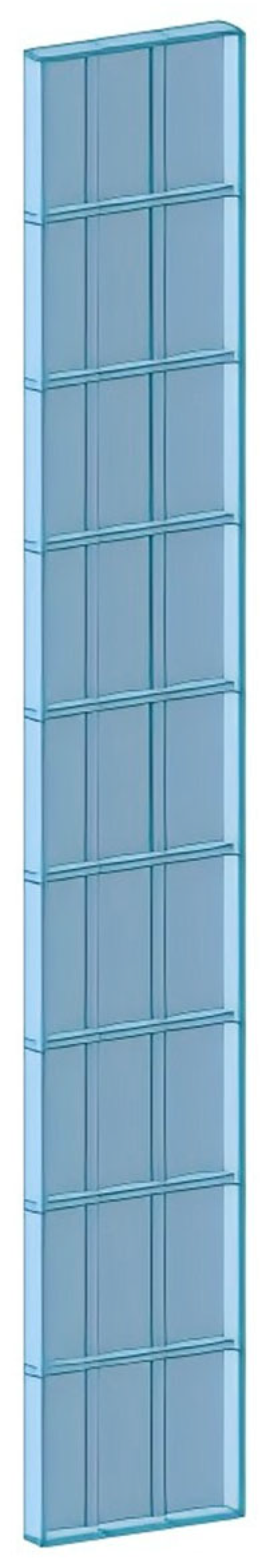
Buildings 15 02394 g001
Figure 2. Elevation view of the new stainless steel formwork.
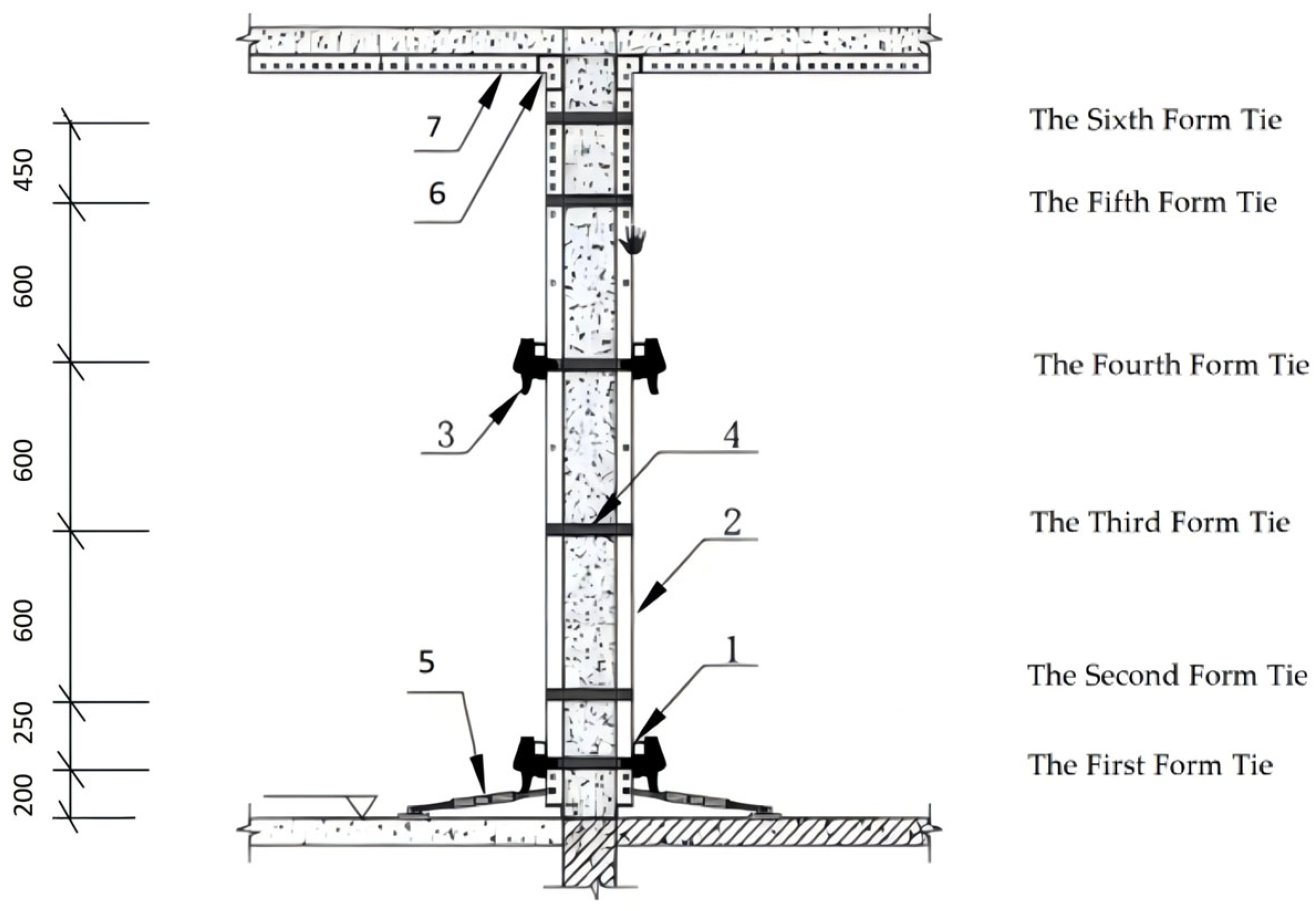
Buildings 15 02394 g002
Figure 3. Schematic diagram of wall formwork configuration and reinforcement. 1—square tube bracing; 2—novel stainless steel wall panel; 3—reinforcement clamp; 4—wall tie; 5—small diagonal brace; 6—C-channel at slab corner; 7—floor slab.
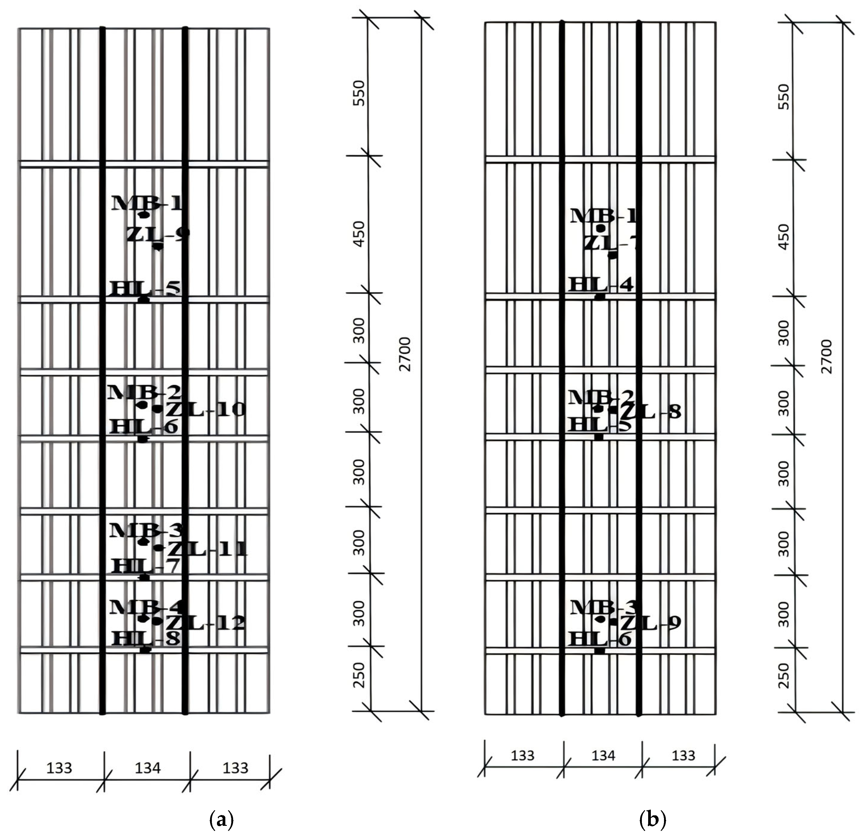
Buildings 15 02394 g003
Figure 4. Arrangement of strain and displacement measurement points on the wall formwork. (a) Arrangement of strain measurement points; (b) arrangement of displacement measurement points.
Buildings 15 02394 g004
Figure 5. Displacement measurement point distribution diagram.
Buildings 15 02394 g005
Figure 6. Schematic diagram of measurement point distribution on wall formwork.
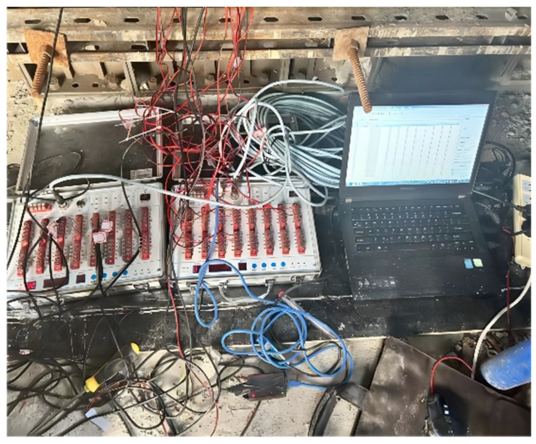
Buildings 15 02394 g006
Figure 7. Schematic diagram of data recording and acquisition.
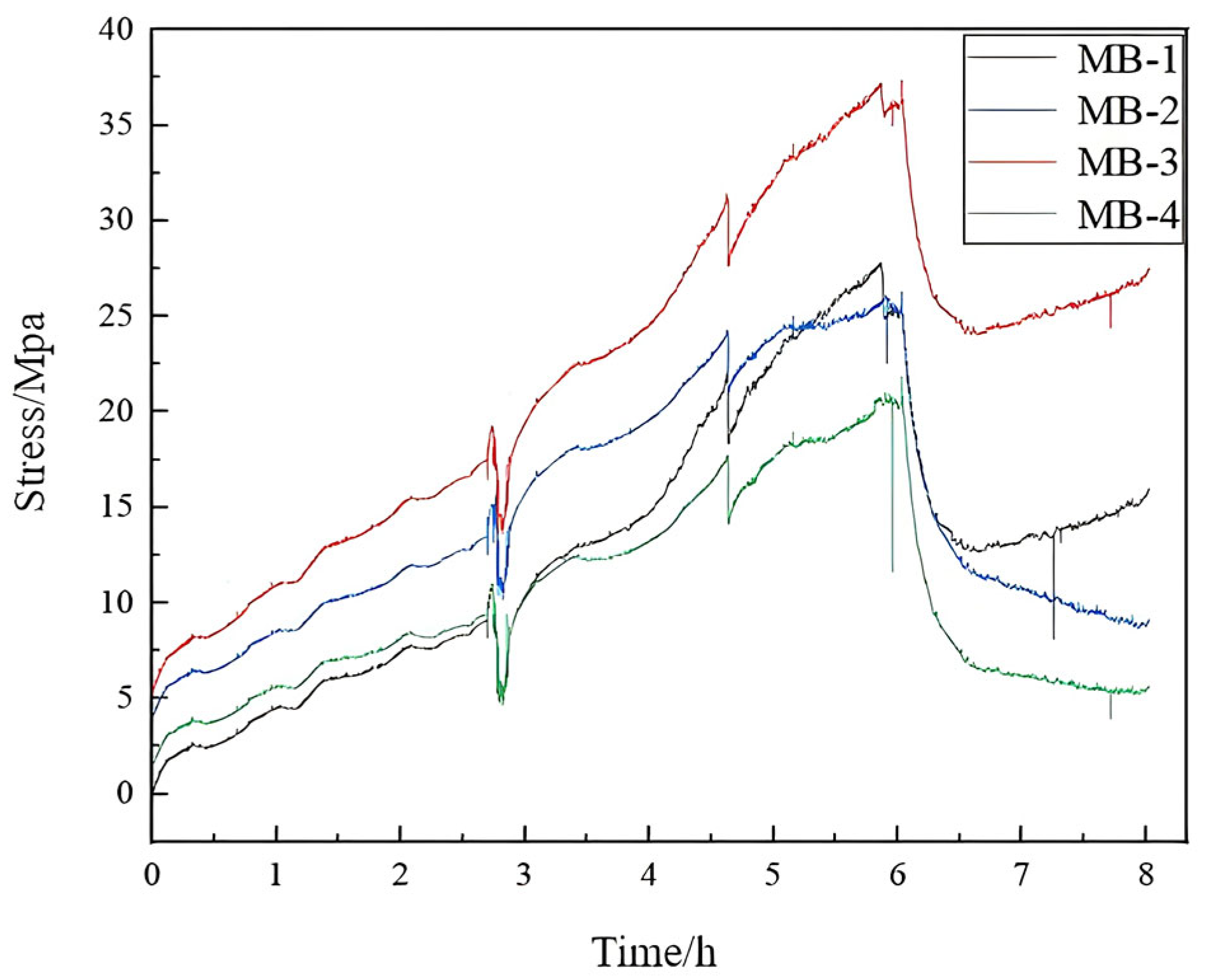
Buildings 15 02394 g007
Figure 8. Comparative stress curves at measurement points on the wall formwork panel.
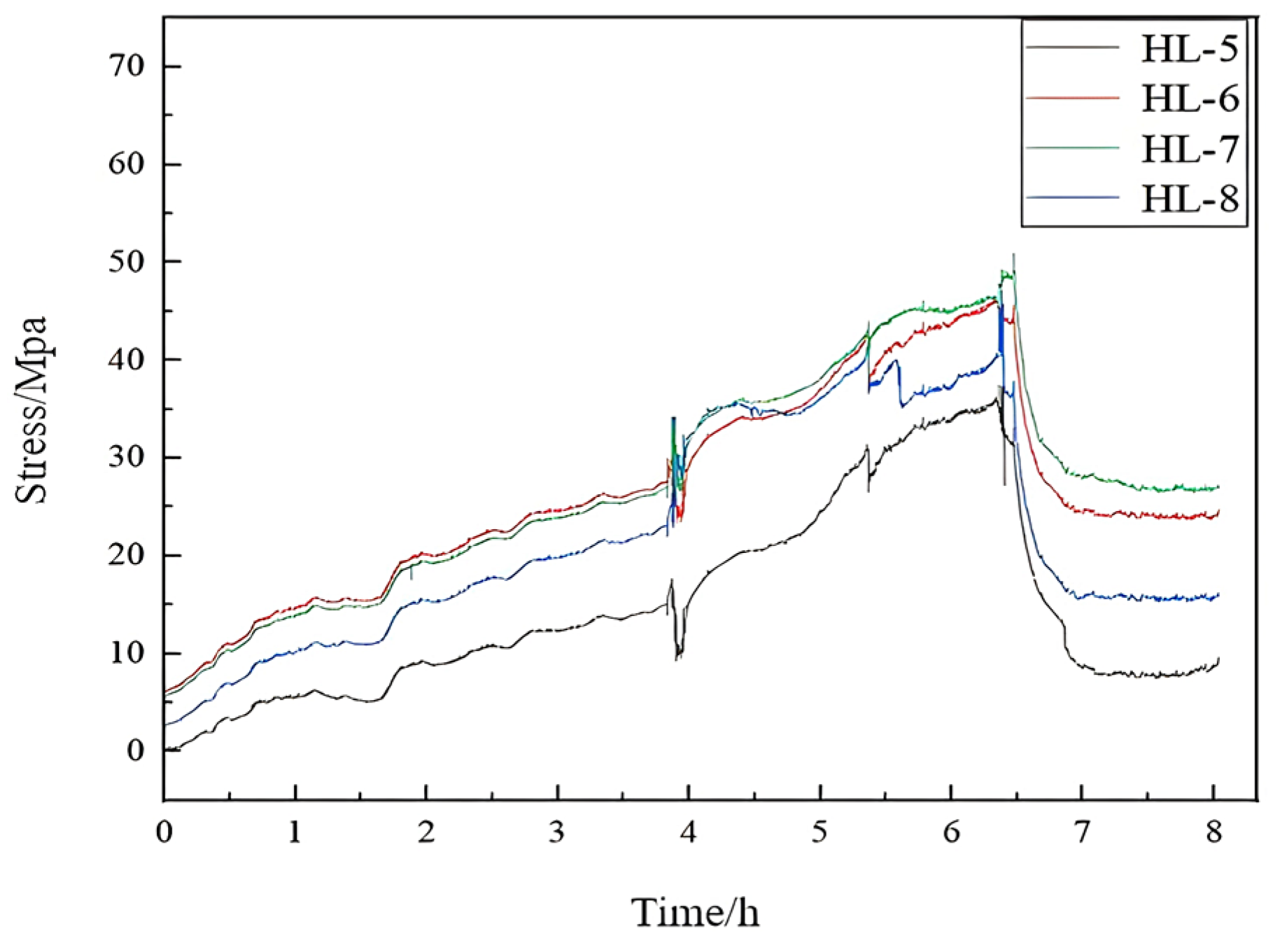
Buildings 15 02394 g008
Figure 9. Comparative stress curves at measurement points on the horizontal ribs of the wall formwork.
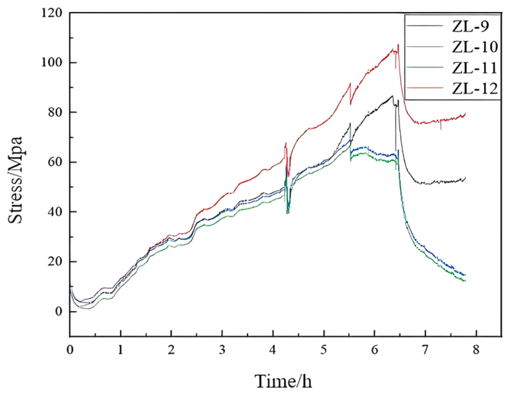
Buildings 15 02394 g009
Figure 10. Comparative stress curves of vertical rib measurement points in the wall formwork.
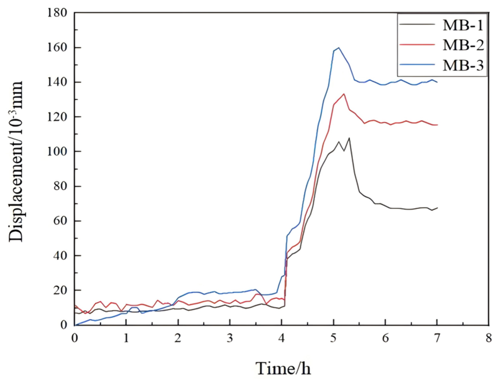
Buildings 15 02394 g010
Figure 11. Comparative displacement curves at measurement points on the wall formwork panel.
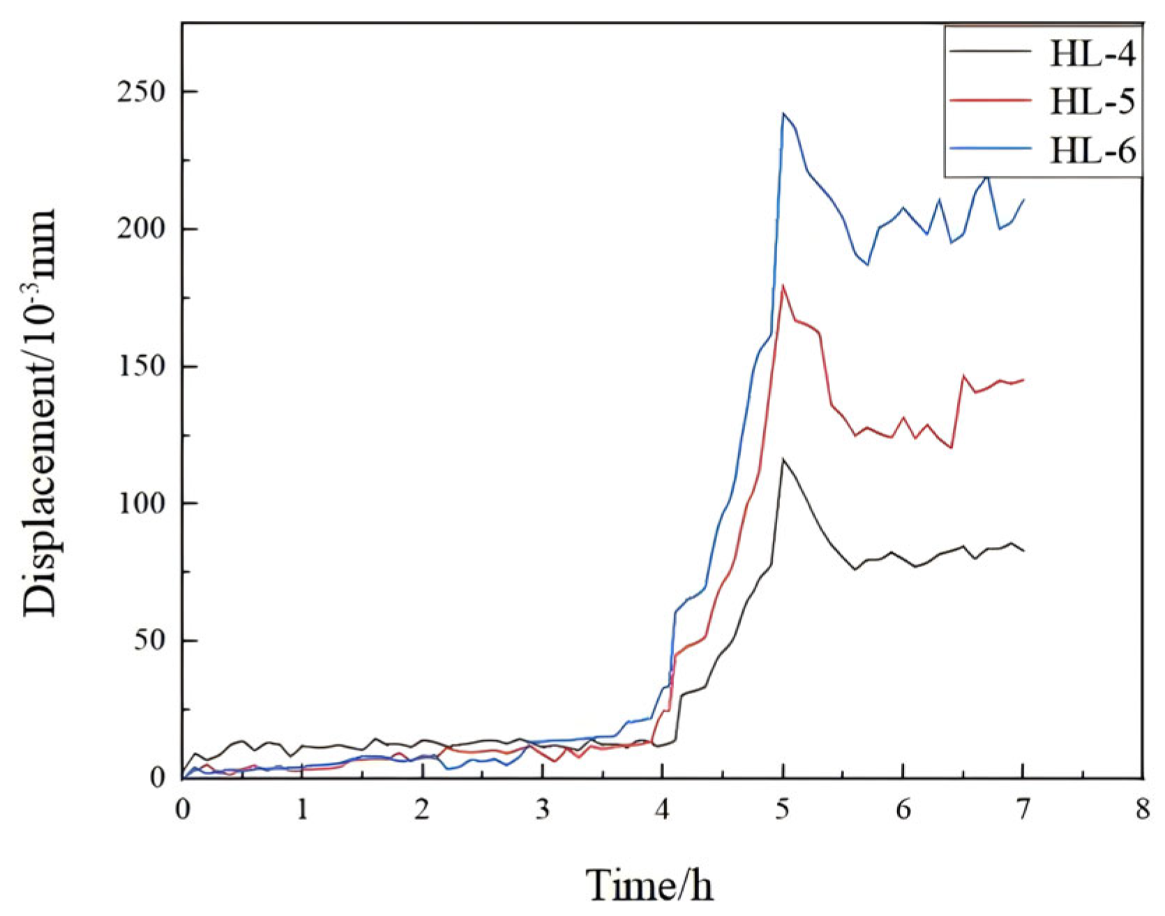
Buildings 15 02394 g011
Figure 12. Comparative displacement curves of measurement points on the horizontal ribs of the wall formwork.
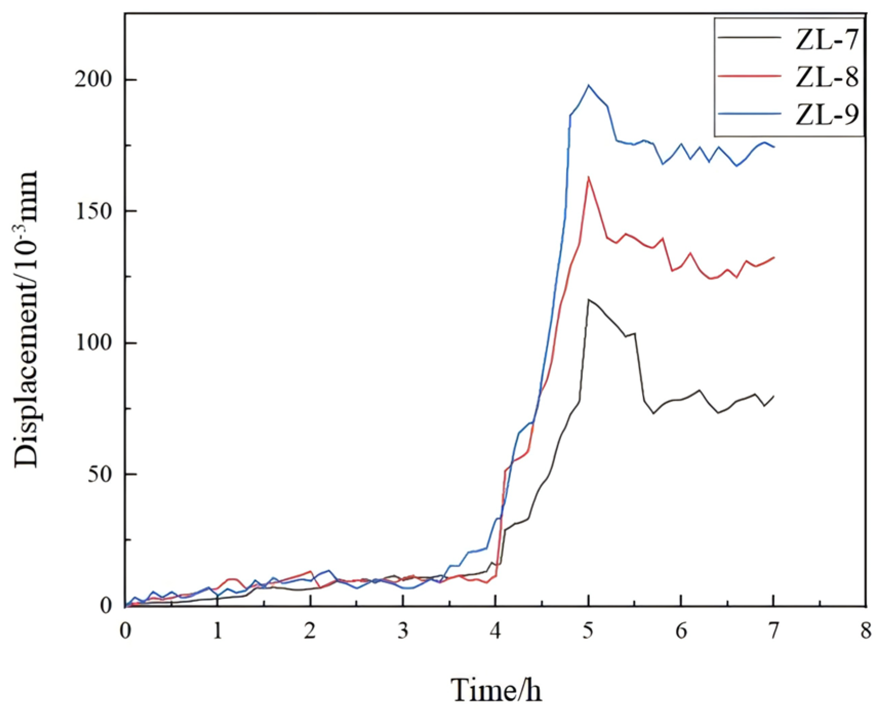
Buildings 15 02394 g012
Figure 13. Comparative displacement curves at the vertical rib measurement points of the wall formwork.
Buildings 15 02394 g013
Figure 14. Simplified calculation model of the formwork panel.
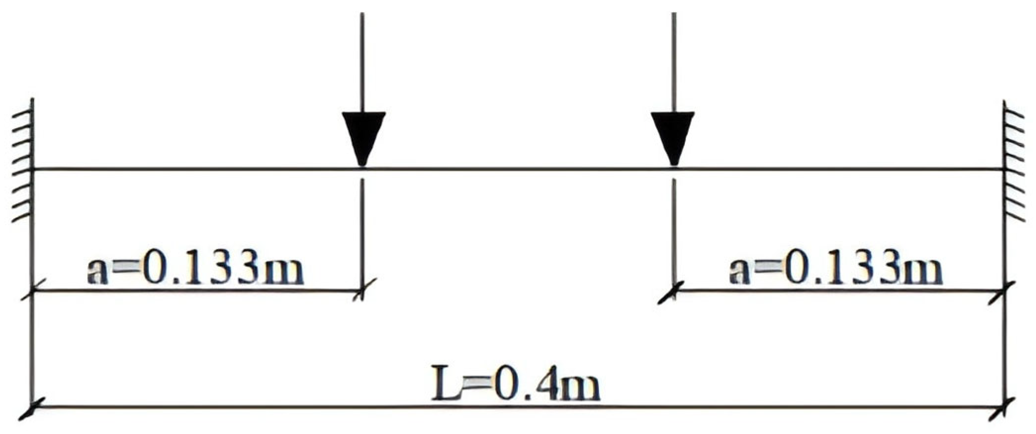
Buildings 15 02394 g014
Figure 15. Simplified load diagram of horizontal rib.
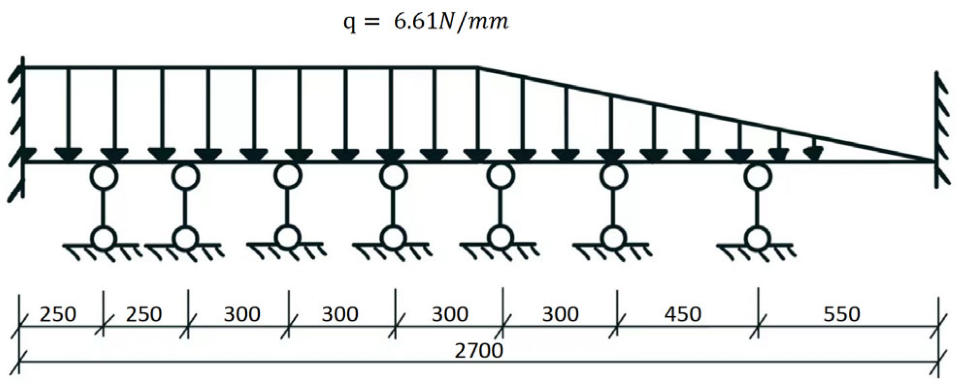
Buildings 15 02394 g015
Figure 16. Simplified force diagram of the longitudinal rib.
Buildings 15 02394 g016
Figure 17. Finite element model of the wall formwork structure.
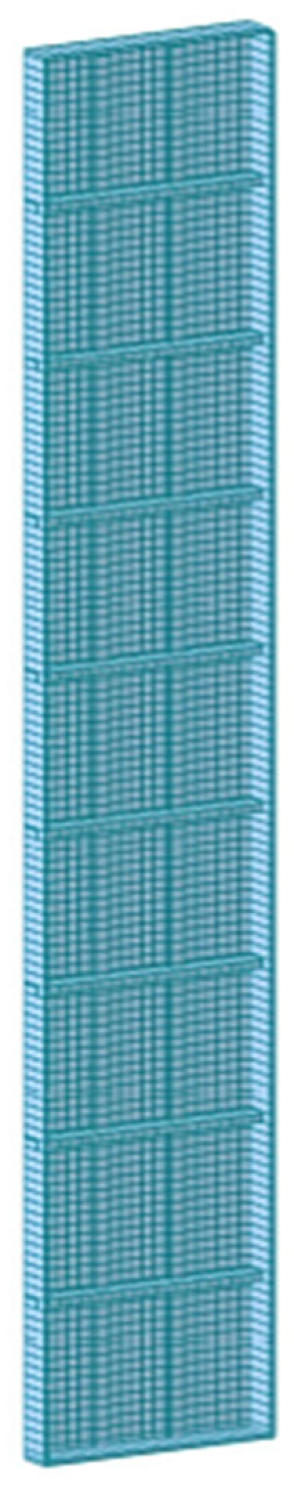
Buildings 15 02394 g017
Figure 18. Mesh layout of the wall formwork model.
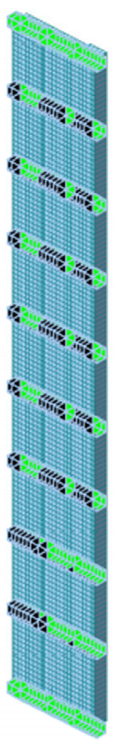
Buildings 15 02394 g018
Figure 19. Boundary conditions applied to the wall formwork model.
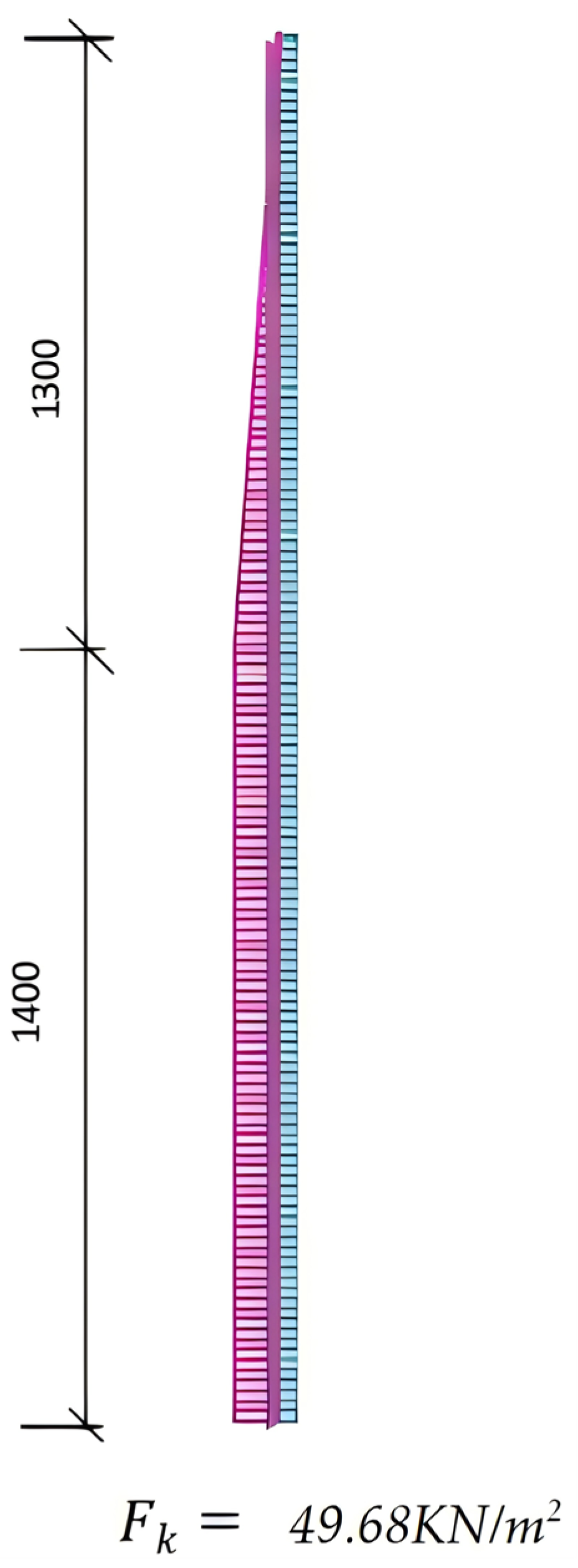
Buildings 15 02394 g019
Figure 20. Load distribution applied to the wall formwork model.
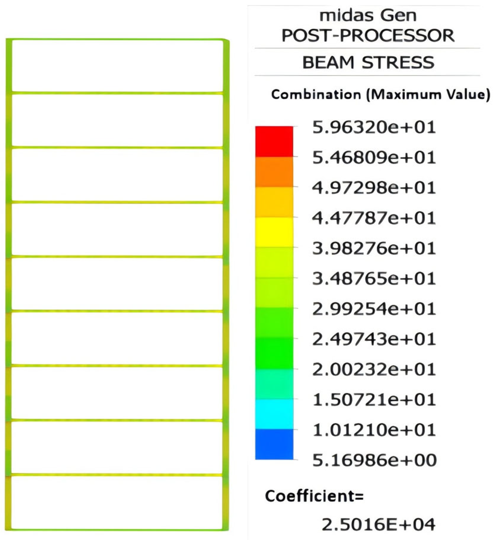
Buildings 15 02394 g020
Figure 21. Stress contour map of variable stress on wall formwork panel.
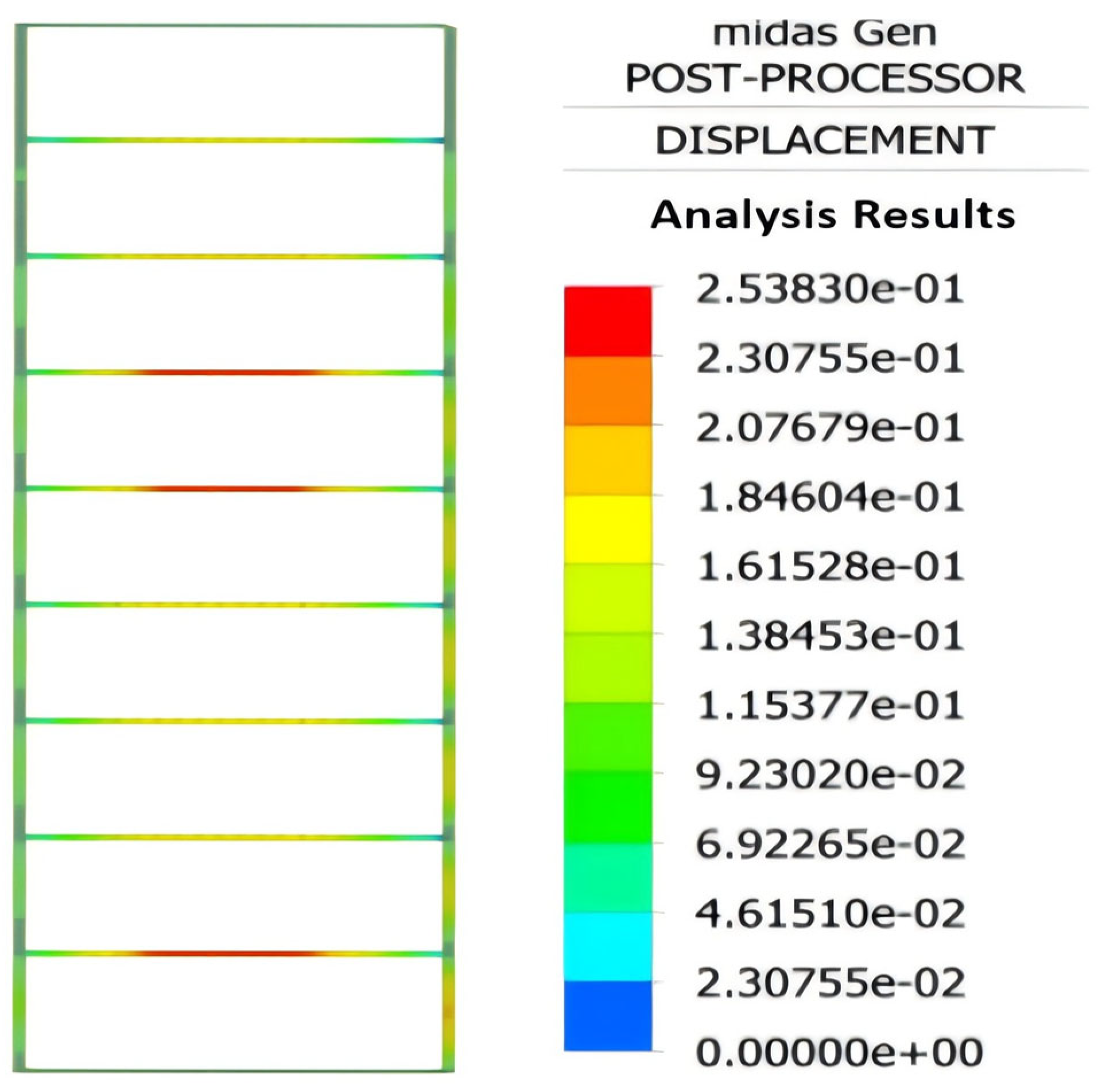
Buildings 15 02394 g021
Figure 22. Displacement distribution of the wall formwork panel.
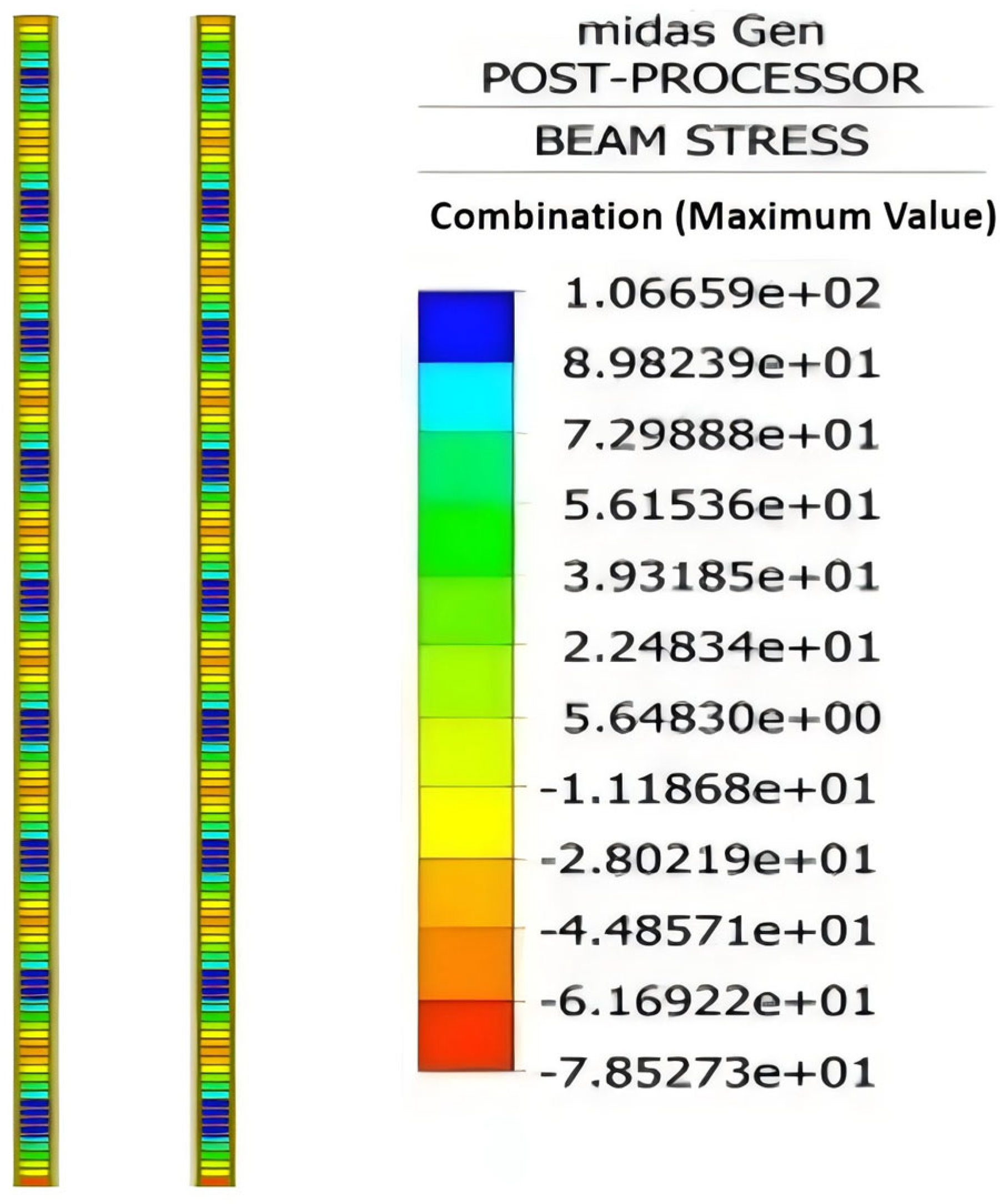
Buildings 15 02394 g022
Figure 23. Stress contour diagram for varying transverse rib dimensions.
Buildings 15 02394 g023
Figure 24. Displacement contour diagram for varying transverse rib dimensions.
Buildings 15 02394 g024
Figure 25. Stress contour diagram for varying longitudinal rib dimensions.
Buildings 15 02394 g025
Figure 26. Displacement contour diagram for varying longitudinal rib dimensions.
Buildings 15 02394 g026
Figure 27. Diagrams illustrating the effects of panel thickness variation on equivalent stress and displacement. (a) Stress variation curve of wall formwork with different panel thicknesses; (b) displacement variation curve of wall formwork with different panel thicknesses.
Buildings 15 02394 g027
Figure 28. Diagrams illustrating the effects of transverse rib width variation on equivalent stress and displacement. (a) Stress variation curve of wall formwork with different transverse rib widths; (b) displacement variation curve of wall formwork with different transverse rib widths.
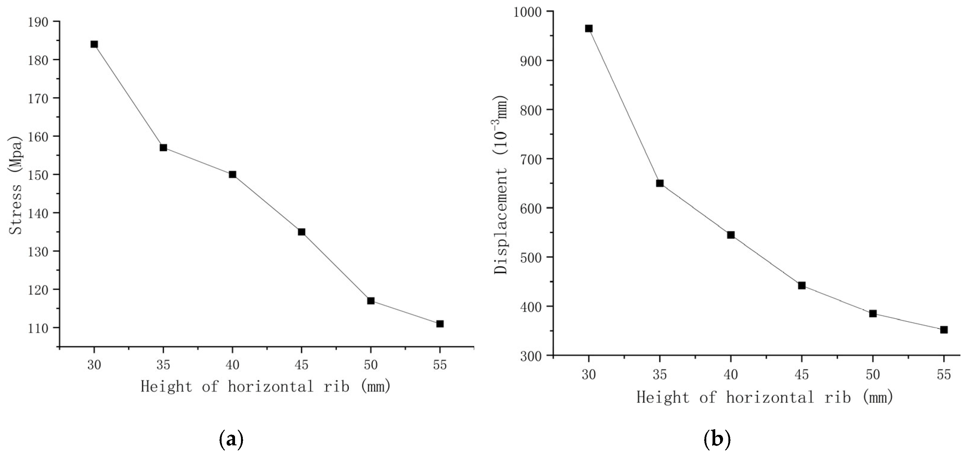
Buildings 15 02394 g028
Figure 29. Diagrams illustrating the effects of transverse rib height variation on equivalent stress and displacement. (a) Stress variation curve of wall formwork with different transverse rib heights; (b) displacement variation curve of wall formwork with different transverse rib heights.
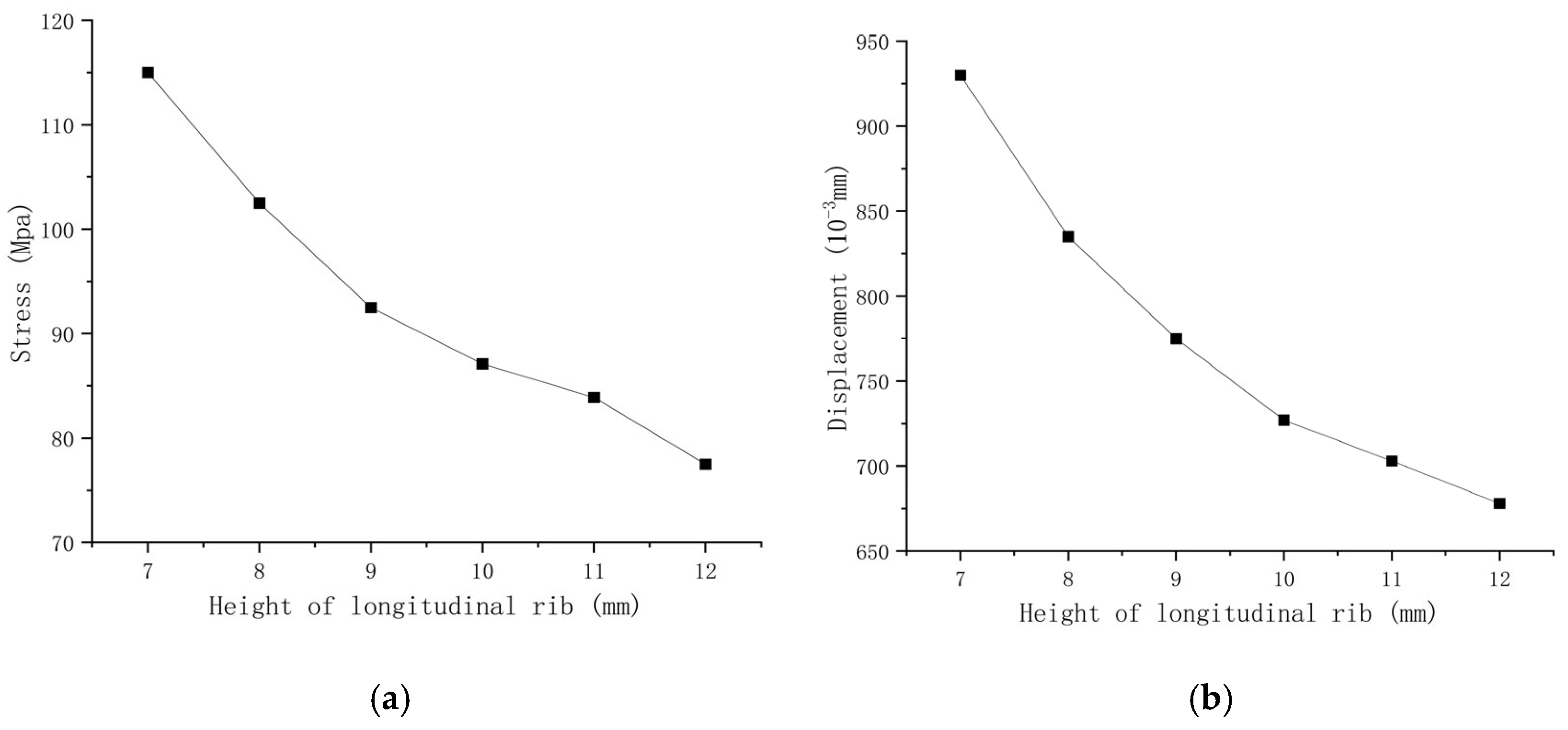
Buildings 15 02394 g029
Figure 30. Diagrams illustrating the effects of longitudinal rib width variation on equivalent stress and displacement. (a) Stress variation curve of wall formwork with different longitudinal rib widths; (b) Displacement variation curve of wall formwork with different longitudinal rib widths.
Buildings 15 02394 g030
Figure 31. Diagrams illustrating the effects of longitudinal rib height variation on equivalent stress and displacement. (a) Stress variation curve of wall formwork with different longitudinal rib heights; (b) displacement variation curve of wall formwork with different longitudinal rib heights.
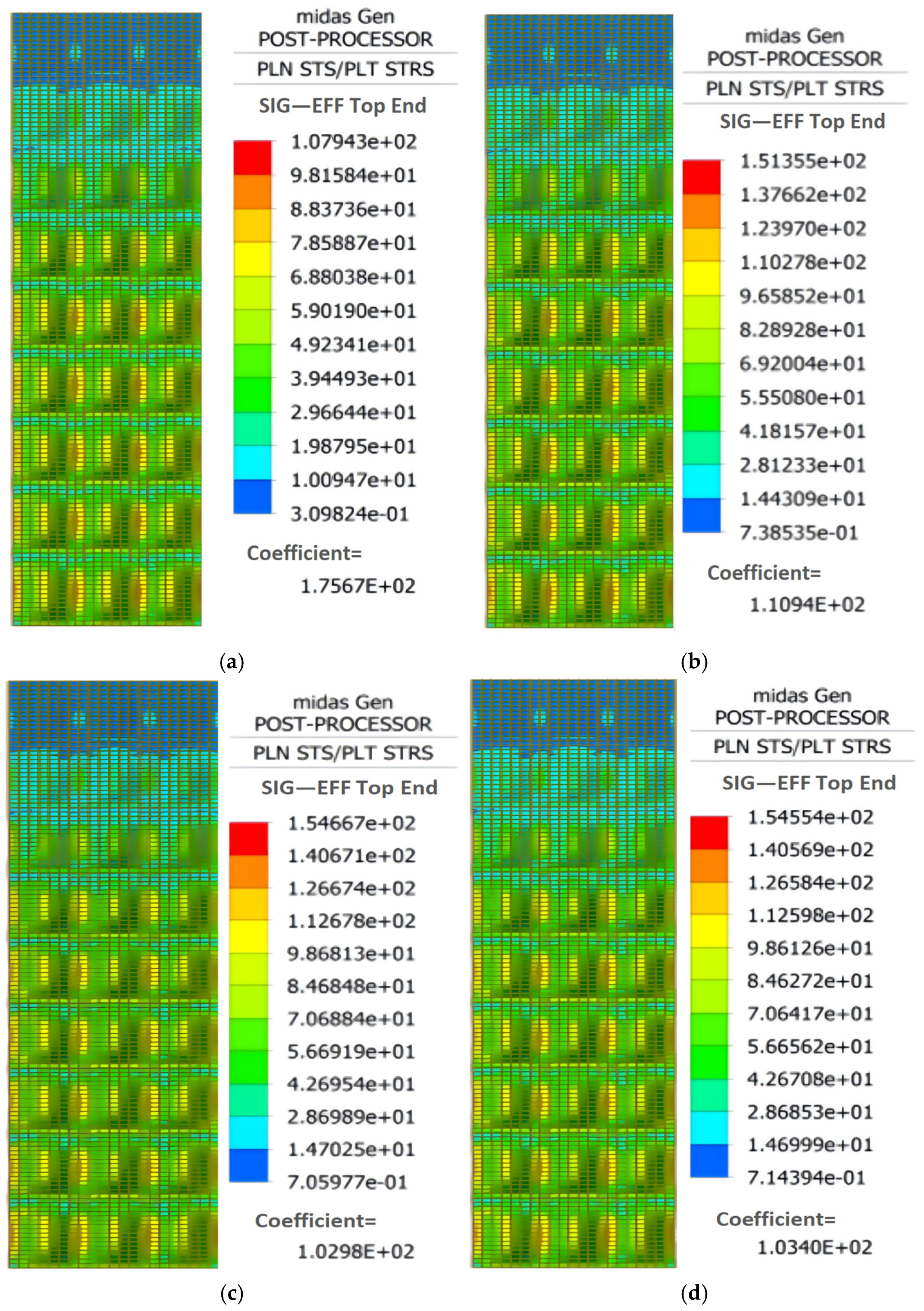
Buildings 15 02394 g031
Figure 32. Stress contour of the optimized wall formwork model. (a) Scheme 2; (b) Scheme 1; (c) Scheme 2. (d) Scheme 3.
Buildings 15 02394 g032
Figure 33. Displacement contour of the optimized wall formwork model. (a) Scheme 2; (b) Scheme 1; (c) Scheme 2. (d) Scheme 3.
Buildings 15 02394 g033
Table 1. Theoretical calculation values for each component of the formwork system.
Component of FormworkExperimental ValueTheoretical Value
PanelTransverse RibLongitudinal RibPanelTransverse RibLongitudinal Rib
Maximum Stress (MPa)37.3756.64102.4736.6752.5573.71
Maximum Displacement (mm)0.160.240.21.40.572.8
Table 2. Material properties of the novel stainless steel formwork.
MaterialElastic Modulus E
( k N / m m 2 )
Poisson’s RatioCoefficient of Thermal Expansion αa ( per   ° C )
HeatingCooling
Alloy steel200~2350.3~0.3111 × 10⁻⁶−8.5 × 10⁻⁶
Gray cast iron70~800.24~0.2511 × 10⁻⁶−9 × 10⁻⁶
Table 3. Comparison of maximum stress and displacement of the panel.
Data TypeOn-Site Concrete Pouring TestFinite Element AnalysisRelative Error (%)
Maximum Stress (MPa)37.3735.684.6
Maximum Displacement (mm)0.200.215.2
Table 4. Comparison of the maximum stress and displacement of the wall formwork transverse ribs.
Data TypeOn-Site Concrete Pouring TestFinite Element AnalysisRelative Error (%)
Maximum Stress (MPa)56.6459.635.3
Maximum Displacement (mm)0.240.254.1
Table 5. Comparison of maximum values for longitudinal rib variables.
Data TypeOn-Site Concrete Pouring TestFinite Element AnalysisRelative Error (%)
Maximum Stress (MPa)102.47106.664.1
Maximum Displacement (mm)0.160.176.3
Table 6. Comparative analysis of key parameters in wall panel components.
Component of FormworkTheoretical Simplified CalculationOn-site Concrete Pouring TestFinite Element Analysis
PanelTransverse RibLongitudinal RibPanelTransverse RibLongitudinal RibPanelTransverse RibLongitudinal Rib
Maximum Stress (MPa)36.6752.5573.7137.3756.64102.4735.6859.63106.66
Maximum Displacement (mm)1.40.572.80.160.240.200.210.250.17
Table 7. Parameter specifications of each design scheme.
SchemeThickness/mmTransverse Rib Width/mmTransverse Rib Height/mmLongitudinal Rib Width/mmLongitudinal Rib Height/mm
Original1.5020453010
Scheme 11.251535259
Scheme 21.251535258
Scheme 31.251540258
Table 8. Performance comparison of different design schemes for stainless steel wall formwork.
SchemeMaximum Displacement (mm)Maximum Stress (MPa)Optimization Percentage (%)
Original0.77107.9/
Scheme 10.92151.410.32%
Scheme 21.31154.711.21%
Scheme 31.30130.910.93%
Disclaimer/Publisher’s Note: The statements, opinions and data contained in all publications are solely those of the individual author(s) and contributor(s) and not of MDPI and/or the editor(s). MDPI and/or the editor(s) disclaim responsibility for any injury to people or property resulting from any ideas, methods, instructions or products referred to in the content.

