Article

Analysis and Application of Critical Pressure Prediction Model for Surface Leakage of Underwater Shallow Buried Jacking-Pipe Grouting

1
Anhui Province Key Laboratory of Building Structure and Underground Engineering, Anhui Jianzhu University, Hefei 230601, China
2
First Engineering Co., Ltd. of CTCE Group, Hefei 230041, China
3
Chengji Railway Engineering Technology Co., Ltd., Hefei 230011, China
*
Author to whom correspondence should be addressed.
Buildings 2025, 15(13), 2359; https://doi.org/10.3390/buildings15132359
Submission received: 15 June 2025 / Revised: 1 July 2025 / Accepted: 3 July 2025 / Published: 5 July 2025
(This article belongs to the Section Building Structures)

Abstract

Jacking-pipe construction has the advantages of high mechanization, low environmental impact and fast construction speed. It is widely used in the project of underground pipeline under river. However, jacking-pipe grouting under shallow burial conditions is prone to cause surface bubbling problems. Based on the jacking-pipe project of Meichong Lake in Changfeng County, Hefei, this paper discussed the mechanism of grouting surface leakage, and defined the relationship between the critical pressure of jacking-pipe grouting and the ultimate pressure of shear damage of mud jacket. Mechanical model of surface leakage from shallow buried jacking-pipe grouting was established. A general mathematical expression for the grouting critical pressure was derived and a sensitivity analysis was performed. A numerical model was established based on the background engineering, and multiple sets of grouting pressure conditions for simulation and analysis were set up. The results showed that the cohesive force c , the angle of internal friction φ , and the overburden thickness h s were all approximately linearly and positively correlated with the critical pressure of grouting. When the grouting pressure was less than 197.54 kPa the surface settlement increased. When this value was exceeded the surface displacement changed from settlement to uplift and the risk of slurry bubbling increased significantly. The theoretical calculation matched the value of grouting critical pressure from numerical simulation. The actual grouting pressure in the project was lower than the theoretical grouting critical pressure value and no slurry bubbling occurred during construction, which had verified the reliability of the theoretical model. This study can provide theoretical basis and investigation ideas for the setting of reasonable grouting pressure in similar projects.

1. Introduction

The crossing of underground pipelines underneath rivers is a common construction during the construction of water supply, drainage, heat and power infrastructures [1,2,3,4,5,6]. Because this construction requires a high degree of mechanization, low environmental impact, fast construction speed and small footprint, the construction of underground pipelines crossing rivers underground often adopts the jacking-pipe scheme [7,8,9]. Pipe–soil friction is an important factor in the constraints of jacking-pipe construction (especially for large jacking-pipe cross sections or long jacking-pipe distances [10]). Resistance-reducing mud is a common way to reduce the frictional resistance between pipe and soil [11,12,13] (forming a mud film around the pipe, changing the pipe–soil contact friction from dry friction to wet friction, which in turn reduces the frictional resistance between pipe and soil). When a jacking pipe crosses a river under shallow or ultra-shallow burial conditions and the grouting pressure is not properly controlled, leakage of slurry from the ground surface is highly likely to result [14,15,16]. This can pose a serious threat to the water environment, which not only wastes materials but can also cause serious construction safety accidents [17]. Therefore, the study of jacking-pipe grouting surface leakage has important theoretical significance and engineering application value.
When a jacking pipe crosses underneath a river, the stratum being traversed mainly consists of clay, silt, sandy soil, silt and silty soil. Sometimes a rock stratum is also encountered when drilling. According to the surface leakage mechanism of jacking-pipe grouting, the traversed strata can be categorized into four types: viscous confined strata, permeable strata, fissure leakage strata and rocky strata [18]. In this case, a permeable stratum consists mainly of sandy, chalky-type soils or gravelly soils with large particles. A permeable stratum has high porosity ratios due to weak inter-particle connections and large pores (especially in slightly dense or less dense soils). The diffusion stage of slurry is mainly categorized into filling diffusion, penetration diffusion, compression diffusion [19] and splitting diffusion. These four diffusion modes can occur simultaneously or sequentially during the actual construction process [20]. Slurry for jacking-pipe grouting in the permeable stratum usually gradually fills the pore space and percolates along it [21,22,23]. At this point Darcy’s law can be adapted. When the grouting pressure reaches a certain value, the slurry may penetrate to the surface along the pores, which is manifested as infiltration damage.
In the process of pipe-jacking grouting construction, the reasonable control of grouting pressure is an important factor for the success of the engineering. If the grouting pressure exceeds a certain value, the slurry will leak to the surface and cause infiltration damage. This value is defined as the critical grouting pressure. Based on the maximum energy release rate (MERR) criterion, M. Yazdani and A. Majdi [24] predicted the critical grouting pressure. Excessive grouting pressure can cause new cracks or crack enlargement in the rock mass. Therefore, [24] used the steady state of the jointed rock mass as a criterion to define the critical grouting pressure. The research results of [24] are aimed at the special stratum of jointed rock formations and do not apply to soil formations. However, for municipal projects, most of the strata where the project is located are soil layers. Li Chunlin [25] introduced a safety factor to derive the optimal grouting pressure. However, this study did not discuss the maximum grouting pressure value. Therefore, we derived the maximum grouting pressure (critical grouting pressure) from the background engineering, surface leakage mechanism and effective stress principle. This is an improvement or addition to our study to [25]. In this paper, the critical pressure in the case of leakage from the jacking-pipe grouting surface was defined, and the prediction model of surface leakage from jacking-pipe grouting in a permeable stratum was established. A method for calculating the critical pressure for surface leakage from jacking-pipe grouting in permeable stratum was proposed, and a general mathematical expression for the calculation method was derived. Combined with the actual grouting parameters of the project, the correlation laws among the parameters were analyzed. This paper then addressed practical engineering problems. The objective of the work is to provide a reliable theoretical expression for the critical grouting pressure, to study the main factors affecting the critical grouting pressure and to investigate the influence of the grouting pressure on the surface displacement.

2. Critical Pressure Definition and Leakage Mechanisms in Grouting Surface

During the synchronized grouting jacking process (shown in Figure 1), thixotropic mud flows out of the grouting holes. Due to the effect of self-weight, the over-excavated voids of the jacking pipe are filled with thixotropic mud. At this point the disturbed mud takes on a gelatinous consistency, which indicates that this can reduce stratum losses [20]. At the same time, the mud under grouting pressure penetrates into the soil around the pipe. A stratigraphic geotechnical body is an aggregate of solid particles with porous interconnecting features. This interconnected pore feature provides channels for mud to seep through the stratum. Due to the complexity of the physical properties of the stratigraphic geotechnical body itself, the pore morphology in the geotechnical body is also complex and variable, which causes the infiltration channels to vary greatly from location to location. Slurry is mainly a mixture (dense permeable blocks) composed of solid-phase particles and liquid-phase bodies. When the slurry begins to come into contact with the stratum, the pressure of the slurry acting on the contact surface is greater than the pressure of the water in the stratum. The solid-phase fines and liquid-phase components of the slurry enter the stratum through the infiltration channel, which in turn causes the infiltration channel to silt up. As time goes by, the permeable stratum channels are gradually filled with fine-grained components, and many permeable blocks are cemented together. When a certain level of infiltration is reached, the mud no longer spreads and is eventually completely enclosed, forming a mud skin. At this point the static mud takes on a gelatinous consistency, forming a dense and impermeable mud jacket.
The mud jacket blocks the exchange of material between the soil and the mud, which stops the mud from flowing out and fills the over-excavated void around the perimeter of the pipe. Effective stresses and excess pore water pressure induced by jacking-pipe construction cannot be dissipated quickly under the closed conditions of the mud jacket. The surrounding soil stratum remains stable under the compacting action of the effective stresses, which prevents excessive surface stratum. Under the protection of the mud jacket, the pipe becomes floating due to mud buoyancy, and its effective weight is reduced. At this moment, the thixotropic mud converts the dry friction between the pipe and the soil layer into liquid friction, which can reduce the jacking-pipe friction resistance and soil disturbanc. In the process of jacking, as the jacking distance increases, the contact area between the pipe and the soil increases, and the friction is greater, which in turn increases the difficulty of construction. Thixotropic mud converts dry friction into liquid friction while filling over-digging voids caused by differences in pipe and pipe-jacking machine dimensions. The grouting pressure generated by the thixotropic slurry supports the soil stratum caused by the soil stress release. Therefore, thixotropic mud is widely used.
When the leakage channels of the mud in the stratum are closed, the slurry develops an excess hydrostatic pressure, which can cause additional stresses in the stratum. When the additional stress in the stratum reaches a certain level, the stratum will be deformed and damaged. When the stratum breaks down, leakage channels for the mud are formed again. Subsequently, the stratum leakage channels are gradually filled with fine-grained components. Many permeable blocks are bonded together to form a mud jacket, and leakage channels are closed again, as shown in Figure 2.
The above process will cycle back and forth in turn. When the leakage channel extends to the surface, it will cause bubbling to occur. It can be seen that the initiating condition for the occurrence of bubbling is the deformation of the stratum and the forming of a new leakage channel. Therefore, whether or not surface bubbling occurs depends primarily on the maximum pressure that the stratum can withstand without damage and the relative magnitude of the mud pressure. If the slurry pressure is greater than the critical pressure for stratum damage, slurry bubbling occurs. Grouting pressure control is the key to preventing surface bubbling under conditions where there is a good match between formation-specific features and mud.

3. Critical Pressure Theory Analysis

3.1. Predictive Modeling

The following assumptions were made for the construction of the critical pressure model for surface leakage of shallow buried river-crossing jacking-pipe grouting.
(1)
The slurry pressure was stabilized [26], which meant that the pressure loss due to diffusion of the grouting pressure was not considered;
(2)
The slurry wall was formed over a short period of time, or the slurry wall was stabilized. The strength of the mud film was sufficient, which meant that the mud film was a complete seal for the leakage channel until shear damage occurred in the soil;
(3)
The mud film caused by the slurry was horizontal. The additional stresses attached to the sealing surface by the liquid column were not affected by changes in the depth of the seal.
Based on the above assumed conditions, a microcell of the stratum soil contact surface was taken as shown in Figure 3.

3.2. Derivation of Critical Pressure Equation

According to the engineering application, a simplified model was constructed, and the following assumptions were made. The hydrostatic pressure of the river was constant and pressure changes due to river flow were ignored. An elastic theoretical formulation was applied to the soil, which was considered as a homogeneous, isotropic, semi-infinite spatial elastic body. When considering the shear stresses of the soil, the effective stresses were involved in the calculation according to the principle of effective stresses, since the upper soil was saturated. The pore water pressure and effective stress were independent of time. The mud wall in the leakage channel was formed in a short period of time, and the mud film was strong. The mud film was a complete seal to the leakage channel until shear damage occurred in the soil. Therefore, infiltration consolidation of saturated soils was neglected. The grouting pressure was considered to be a certain stable value, which implied that pressure loss due to instability of the grouting pump pressure or pressure spreading of the slurry in the soil was not taken into account.
Based on the background engineering, a unit cell was intercepted at any point in the soil surrounding the jacking pipe for force analysis. The unit was a cube with sides of length d l , and its own gravity was ignored. The unit had a tendency to move upwards under slurry pressure. Thus, there is a downward shear force F s generated there, as shown in Figure 3a. At the same time, the unit is also affected by the gravity of the upper soil G s , the grouting pressure F p , and the surrounding soil pressure.
The unit body is balanced by forces in the vertical direction:
F z = F p G s 4 F s = 0
Here, F p is the grouting pressure, kN; G s is the gravity of the upper soil stratum, kN; F s is the shear force, kN.
It can be further seen that:
F p = p m d l d l G s = σ G d l d l F s = τ d l d l
Here, p m is the grouting pressure per unit area, kPa; σ G is the effective stress of saturated soil, kPa; τ is the lateral shear stress, kPa.
Since the shear stresses within the soil can be carried only by the soil skeleton, the shear strength of saturated soil is related to the effective stress. Equation (3) can be obtained.
σ G = γ w h w + γ s a t h 0 u = γ w h w + h 0
Here, σ G is the total stress, kPa; u is the pore water pressure, kPa; γ w is the river water gravity, which is approximated to take the gravity of the water, kN/m3; γ s a t is the saturated gravity of the overburden of the header pipe, kN/m3; h w is the depth of the river, m; h 0 is the distance of the unit from the riverbed, m.
According to the effective stress principle for saturated soils proposed by Terzaghi:
σ G = σ G u = γ s a t γ w h 0 = γ h 0
Substituting Equation (4) into Equation (2) yields:
G s = γ h 0 d l d l
Substituting Equation (2) and Equation (5) into Equation (1) and simplifying:
τ = P m γ h 0 4
Taking the plane stress state as an example, the model was simplified, and the stress analysis was performed as shown in Figure 3b. Lateral friction resistance is the static earth pressure. Positive stresses in the horizontal direction resisting the upward movement of the unit:
σ x = K γ h 0
Here, K is the coefficient of static earth pressure, the value of which can be determined by the empirical formula, K = 1 sin φ , ( φ is the effective angle of internal friction of the soil).
Positive vertical stress:
σ y = P m
According to Equation (6), the tangential stress in the x plane:
τ x = P m γ h 0 4
Tangential stress in the y plane:
τ y = 0
Based on the stress analysis, the maximum principal stress σ 1 and the minimum principal stress, σ 3 can be determined from the Mohr stress circle:
σ 1 = 1 2 σ x + σ y + 1 2 σ x σ y 2 + 4 τ x 2
σ 3 = 1 2 σ x + σ y 1 2 σ x σ y 2 + 4 τ x 2
The monolith was assumed to be in limiting equilibrium. Calculated using the effective stress intensity index according to the Mohr–Coulomb strength theory:
sin φ = σ 1 σ 3 σ 1 + σ 3 + 2 c cot φ
Here, c is the effective cohesive force of the soil, kN/m2. It was obtained by substituting Equations (12) and (13) into Equation (14) and simplifying:
sin φ = σ x σ y 2 + 4 τ x 2 σ x + σ y + 2 c cot φ
Substituting Equation (6) into Equation (14):
L = σ x = γ h 0 M = 2 c cos φ
Furthermore:
P m 2 sin 2 φ 5 4 + P m ( 2 K L sin 2 φ + 2 L + 2 M sin φ + 2 K L + L 2 ) + K 2 L 2 sin 2 φ K 2 L 2 + 8 KLMsin φ + 4 M 2 L 2 4 = 0
Obtained from the formula for finding the roots of a quadratic equation:
Δ = 24 K L M sin 3 φ + 17 K 2 L 2 + 2 K L 2 + L 2 12 M 2 sin 2 φ + 48 K L M + 2 L M sin φ K 2 L 2 + 2 K L 2 + 20 M 2 L 2
As a result:
P m = 2 K L sin 2 φ + 2 M sin φ + 2 K L + L 2 ± Δ 5 2 2 sin 2 φ
The larger value calculated by Equation (18) is the maximum grouting pressure at any point in the soil layer. At this moment the soil stratum is in a critical state of imminent shear damage. The situation considered here is that the jacking-pipe grouting direction is vertically upward. Then when the soil in contact with the jacking pipe undergoes shear damage, slurry bubbling occurs in the soil stratum. It can be seen that the critical pressure for surface leakage of shallow buried jacking-pipe grouting is mainly related to the nature of the soil ( c , φ , γ , K ) and the depth of the jacking-pipe burial. For a rocky stratum, Xu Bin et al. [26] thoroughly investigated the relationships among the side pressure coefficient, crack inclination, overburden pressure and grouting pressure.

3.3. Calculation Reasonableness Validation

In order to verify the reasonableness of the above critical pressure derivation results, a comprehensive project in Changfeng County, Hefei City, China for drainage and flood control, as well as rainwater and sewage diversion, was used as a case study to initiate the verification. Where the project crosses the Chu River section, the jacking-pipe program adopted mud–water-balanced construction. The total length of the project site line is 7015 m, as shown in Figure 4. The stratigraphic distribution of the project site is, from top to bottom, fill, silty chalky clay, clay, silty clay, strongly weathered mudstone and weathered mudstone.
According to the actual jacking-pipe engineering of the background project, the thickness of the overlying soil layer of the jacking pipe, h s , was taken as 3.0 m, and the depth of the river water, h w , was taken as 3.0 m. The jacking pipe crossed the stratum of silty clay. Its density, ρ s , was taken as 1.922 kg/m3, cohesion,   c , was taken as 40 kPa, friction angle, φ , was taken as 15.5°, and gravitational acceleration, g , was taken as 10 m/s2.
Bringing the above parameters into Equations (15)–(18), the results of the calculations are shown in Table 1.
The values used for grouting pressures in the background project were 150–180 kPa when crossing the river. According to the results calculated in Table 1, it can be seen that the theoretical maximum grouting pressure (critical pressure) under the condition of this background project is 197.538 kPa. The grouting pressure (150–180 kPa) during actual project construction is less than the theoretical critical pressure (197.538 kPa).
Engineering data was normal during construction of the river crossing. The jacking-pipe project was completed smoothly and successfully, with good construction quality, and successfully passed acceptance and was put into operation. This can verify the rationality and feasibility of calculating the critical pressure.

4. Numerical Simulation Calculation and Analysis of Jacking-Pipe Grouting Construction

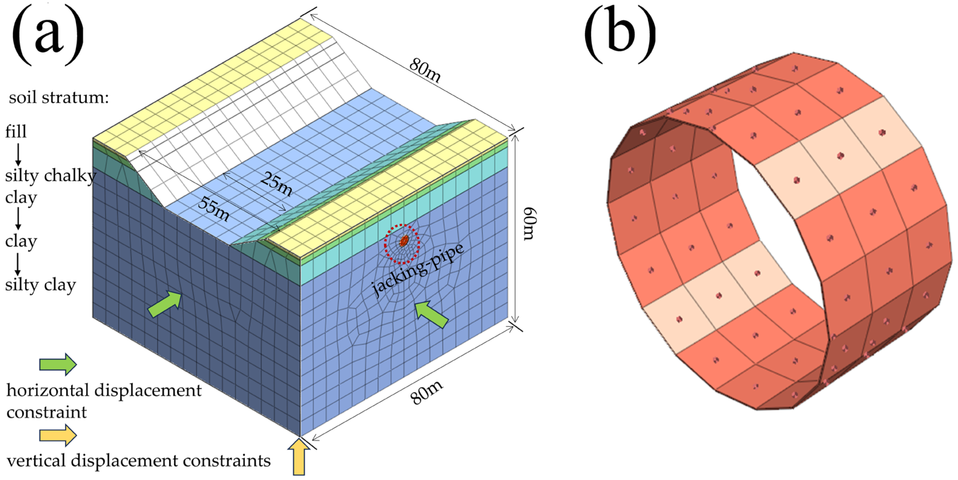
4.1. Numerical Simulation Model Generalization

Based on the background engineering in Section 3.2, the mud–water-balanced jacking pipe project was simplified in order to more easily simulate the grouting pressure situation during jacking. The size of the numerical simulation model was 3–5 times the size of the soil surrounding the jacking-pipe project. The length, width and height of the numerical model were 80 m × 80 m × 60 m, as shown in Figure 5a. The stratum was divided into four layers, namely fill (1 m), silty chalky clay (1.95 m), clay (6.7 m) and silty clay. The material property parameters for each stratum simulation are shown in Table 2. The material property parameters were sourced from the survey data of the background engineering.
The Chu river valley model has a maximum width of 55 m, a minimum width of 25 m and a height of 9.46 m. The depth of water in the river valleys varies between 1–10 m during dry and abundant periods. The inner diameter of the mud–water-balanced jacking pipe is 3 m, and the outer diameter is 3.6 m. The thickness of the thin overburden on top of the jacking pipe is 3 m.
The material model used for the stratum was the Mohr–Coulomb model with a grid size of 5 m. The grid size of the jacking-pipe tunnel was 1 m. The contact mode of Boolean calculation was used between the stratum and the excavated tunnel entities and between the various soil strata. Only the upper surface of the model was unconstrained (free surface). Horizontal displacement constraints were applied to the left and right boundaries of the model, and vertical displacement constraints were applied to the lower boundary.
The process of numerical simulation mainly included initial stress field equilibrium, pipe excavation, grouting pressure application, pipe jacking and pipe sheet application. Firstly, the numerical simulation model imposed boundary conditions and self-weight. The initial displacement was cleared to zero. The model started the initial stress analysis. Next, the jacking force was applied at the pipe jacking palm surface, and the excavated soil was blunted. Then, the jacking machine’s shell was activated. The jacking-pipe grouting pressure was activated at the same time as the friction force was applied. Subsequently, the shell of the jacking machine was blunted. The jacking pipe was jacked in, and the pipe sheet was applied. Finally, the soil of the next pipe section was excavated. The shell of the jacking machine was added. The jacking force, grouting pressure and friction force exerted by the previous pipe section were blunted.
The pipe sheet was reinforced concrete material, and the shell of the jacking machine was steel material. Both material models were chosen as elastic models. The material property parameters of sheet and shell are shown in Table 2. The following simplifications and assumptions were made to the model for the focus of the study on grouting pressure:
(1)
The frontal support pressure during jacking-pipe construction was taken from the lateral static earth pressure at the center point of the excavation surface and applied in the form of a circular uniform load over the entire area of the excavation surface. The frontal digging force of the jacking pipe was taken as 88.5 kPa, as shown in Figure 6a.
(2)
The pipe section material was isotropic linear elastomer, and the effect of the joints between the sections was neglected. Pipe–soil friction force was exerted on the outer surface of the pipe shell and the inner surface of the soil around the pipe. The friction between the pipe and soil was a certain value and uniformly distributed along the pipe jacking direction. It was realized by setting a coefficient of friction on the contact surfaces. The friction force was taken as 3.5 kPa, as shown in Figure 6b.
(3)
The mud jacket between the shell and the pipe sheet was simulated using an equivalent layer, as shown in Figure 5b. The modulus of elasticity of the equivalent layer was taken as 1/50 of the pulverized silty clay unit, and its thickness was taken as 2 cm. During the jacking process of the pipe-jacking, a circumferential gap was created between the soil and the pipe-jacking. A drag-reducing thixotropic slurry was injected around the pipe-jacking to reduce the frictional resistance thereafter. In the numerical model, the lost soil area (mud jacket) after the above drag-reducing thixotropic slurry grouting was equivalently replaced by an equivalent layer with a thickness of 2 cm. By varying the properties of the equivalent layer and the setting of the boundary conditions, the change of soil properties during the grouting process can be simulated. This can enable the simulation of simultaneous grouting during jacking [27]. Grouting pressure was the force acting on the pipe sheet and the soil surrounding the pipe sheet. In the simultaneous grouting process, the slurry, under a certain pressure and with a certain grouting speed, infiltrated through the gap of the soil body. The grouting pressure was distributed equally on the upper and lower surfaces of the equivalent layer, and its value was taken as 197.538 kPa, as shown in Figure 6c.
(4)
The initial stresses were considered only the self-weight stresses of the strata. Consolidation settlements of the strata over time were not considered. Groundwater effect was also not considered. Only soil settlement due to the jacking of pipe was considered.

4.2. Calculation of Working Conditions

The jacking-pipe grouting pressure study was closely related to the background project. Surface displacement and deformation monitoring points were arranged on the ground in front of and above the face of the jacking-pipe tunnel along the central axis of the tunnel, perpendicular to the central vertical line of the tunnel and the central vertical line of the face of the jacking-pipe tunnel. In order to obtain the change regulation of the deformation characteristics of jacking-pipe grouting construction with the volume of the grouting pressure, the coefficient of grouting pressure ratio was introduced, as shown in the following Equation (19).
p = P P 0
Here, p is the grouting pressure ratio, kPa; P is the grouting pressure, kPa; P 0 is the initial grouting pressure, kPa.
The initial grouting pressure, P 0 , was taken as 197.538 kPa. The grouting pressures, P , were taken as 0 kPa, 79.015 kPa, 158.031 kPa, 197.538 kPa, 296.307 kPa, 395.076 kPa, 493.845 kPa and 592.614 kPa for the simulation analysis as shown in Table 3.

4.3. Analysis of Calculation Results

As shown in Figure 7, the grouting pressure is from 0 kPa to 592.614 kPa, the maximum values of vertical displacement of soil above the pipe-jacking are −9.127 cm, −7.186 cm, −5.503 cm, −4.763 cm, −3.333 cm, −2.957 cm, −2.784 cm and −3.029 cm, and the maximum values of vertical displacement of soil below the pipe-jacking are 6.030 cm, 5.292 cm, 4.562 cm, 4.219 cm, 3.466 cm, 4.487 cm, 8.398 cm and 16.659 cm. The vertical displacement of the soil above the jacking-pipe grouting increases with the increase in grouting pressure. When the grouting pressure increases to 197.538 kPa, the soil begins to bulge upward. When the grouting pressure continues to increase to 592.614 kPa, the soil bulge deformation continues to grow, and large displacement deformation occurs below the river channel. Under grouting conditions, the grouting pressure can support the soil above the jacking pipe. The slurry fills the void between the jacking pipe and the soil. As the grouting pressure increases, the slurry exerts greater pressure on the soil around the jacking-pipe wall. When the pressure reaches a certain value, the soil around the jacking pipe will split. When the grouting pressure is higher and the grouting volume is more, the cracks will also become bigger and even develop to the surface, so that the slurry will flow out of the surface by extending the cracks and create the phenomenon of slurry bubbling.
The calculation results of the surface deformation of the river bottom at the center of the river perpendicular to the jacking-pipe axis cross-section are shown in Figure 8. The vertical displacement of the ground surface gradually decreases with the rising displacement of the grouting pressure. At the jacking-pipe grouting pressure is less than 197.538 kPa, the maximum vertical displacement of the ground surface above the jacking pipe is manifested as settlement. At the same time, the amount of deformation shows a linear increasing trend, but the amplitude of the increase is small. At 1/2 of the whole jacking distance, the vertical displacement of the ground surface is the maximum value. At the same time, the maximum value of vertical displacement at this time increases with the increase of this grouting pressure. This is not a linear relationship. When the difference between the grouting pressure and 197.538 kPa is larger, the size of the value of the maximum value of vertical displacement is larger. When the grouting pressure is greater than 197.538 kPa, the displacement value is becomes bigger and bigger. With the change of the applied grouting pressure, the soil displacement deformation gradually changes from settlement to bulging. When the grouting pressure is less than the critical pressure, the vertical displacement of the ground surface shows the phenomenon of settlement, and the settlement value appears to peak and then begins to become smaller. This result is basically consistent with the numerical regularity of surface displacement detection of the jacking pipe in Line 1 and Line 3 by Ren Dongjie et al. [28]. However, the results of Ren Dongjie’s study showed that the peak occurred at 3/5 of the total jacking distance, not at 1/2 of the total jacking distance. This was because Ren Dongjie’s background project crosses two rivers. This background project crossed a shallow river and then a deep river. At the same time, the background project had a jacking distance of up to 150 m.
The vertical displacement of the ground surface above the axial direction of the jacking pipe under different grouting pressures is shown in Figure 9. When the pipe-jacking grouting distance is 0–20 m, the vertical displacement of the surface in the axial direction of the jacking pipe is less than 0. When the pipe-jacking grouting distance is greater than 20 m, the displacements under the grouting pressures of 296.307 kPa, 395.076 kPa, 493.845 kPa and 592.614 kPa begin to change from a negative number to a positive number. It can be seen that the vertical displacement of the soil above the axial direction of the jacking pipe manifests settlement when the grouting pressure is less than 197.538 kPa. When the grouting pressure is greater than 197.538 kPa, the displacement of the soil body gradually changes from settlement to bulge, and the value of bulge rises sharply with the increase in the grouting pressure. When the grouting pressure is small, the grouting pressure disturbs the soil less. Higher grouting pressures result in a gradual change from settlement to uplift of the surface soil.
The maximum values in the surface vertical displacement under different grouting pressures in Figure 9 were selected to plot the maximum vertical displacement of the surface versus the grouting pressure, as shown in Figure 10. As shown in Figure 10, the maximum vertical displacement of the ground surface above the jacking-pipe axial direction keeps increasing as the grouting pressure increases. When the grouting pressure is greater than 197.538 kPa, the maximum displacement value changes from negative to positive, i.e., it is a gradual change from settlement to bulge [29]. The maximum displacement value is significantly maximized when the grouting pressure is greater than 250 kPa. The reason for this is that the action of the grouting pressure causes the grouting layer between the pipe and the soil to be squeezed and deformed. Increasing the grouting pressure can play a role in compacting the soil around the pipe section and reducing the settlement of the stratum. However, as the jacking-pipe grouting pressure is increasing, the soil displacement and deformation above the jacking pipe will increase. Therefore, in the construction of thin-covered, large-diameter, mud–water-balanced and river-crossing pipe jacking, attention should be paid to controlling the size of the pipe-jacking grouting pressure to make the best grouting control effect.

5. Discussion

If the grouting pressure is comparable to the formation stress, the grouting pressure can effectively reduce the formation loss and surface settlement. However, in engineering practice, higher pressures of grouting are used in order to minimize surface settlement and to adequately fill the void between the pipe-jacking and the soil. Higher grouting pressures can directly disturb the surrounding soil layer and damage the pipe-jacking structure or cause bolt shearing. Therefore, the critical value of grouting pressure has great value in engineering practice.
According to the analytical derivation of the critical pressure in Section 3.2, it can be seen that the surface-leaking critical pressure of synchronized grouting for river crossing and shallow buried pipe-jacking construction is related to the cohesive force c , the angle of internal friction φ , the thickness of the overburden h s and other factors. The parameter sensitivity of the theoretical solution was analyzed with reference to the construction parameters of mud–water-balanced jacking pipe across Chu River in Changfeng County, Hefei City. When studying the law of distribution of the critical pressure P m as a function of a factor, only the magnitude of this parameter was varied, and all other parameters were assumed to remain constant. When one variable was discussed, the other two variables and other parameters were controlled to remain constant, and the corresponding theoretical values were calculated according to the theoretical formula for critical grouting pressure. When the cohesive force c is at 20~600 kPa (20, 40, 60, 80, 100, 150, 200, 250, 300, 400, 500, 600), the angle of internal friction φ is at 5~30° (5, 10, 15, 20, 25, 30), and the thickness of overburden h s is in the range of 1.0~10.0 m (1, 2, 3, 4, 5, 6, 7, 8, 9, 10), the surface-leaking critical pressure variation characteristics are shown in Figure 11. The process of theoretical calculations is shown in Table 4.
As can be seen in Figure 11, with the increase in the cohesive force c , the angle of internal friction φ and the thickness of overburden h s , the surface-leaking critical pressure P m shows an increasing overall change rule. When only changing the variable of cohesion c, every increase of 1 kPa critical grouting pressure P m is about 4 kPa. When only changing the angle of internal friction, every increase of 1° critical grouting pressure Pm is about 1.6 kPa. When only changing the upper overburden layer, every increase of 1 m critical grouting pressure P m is about 12 kPa. These three parameters have a clear linear relationship with the surface leakage critical pressure P m [30].
Reference [31] concluded that fracture initiation will not occur when the maximum grouting pressure is 2.0–2.5 pw (pw is the groundwater hydrostatic pressure at the grouting segment). However, the critical grouting pressure presented in that study was mainly derived from empirical equations. It is not rigorous and accurate enough. In contrast, our study goes through rigorous condition assumptions, modeling and formula derivation. The critical grouting pressure is an accurate value and not an empirical range. Ma Minglei et al. [27] not only discussed the settlement changes of the ground surface under different grouting pressures, but also revealed the jacking deformation law of circular reinforced concrete pipe under different grouting. Their results showed that with the increase in grouting pressure, the deformation of the upper and lower part of the reinforced concrete circular pipe gradually increased. After the increase in grouting pressure to a certain degree, it did not change much. However, this thesis was based on a single research method. The whole research work was completed by only one method, the numerical simulation. For awful construction conditions, Yang Xian et al. [32] developed a special grouting slurry formulation to improve the slurry properties. This paper also has some limitations. The existing research findings above can be a good addition to the content of this paper. The novelty of this research work lies in the establishment of a prediction model of jacking-pipe grouting pressure for shallow buried river-crossing jacking pipes based on the actual engineering background, and the derivation of an accurate expression for the critical grouting pressure. This means that similar projects will have an important theoretical basis, rather than just relying on the engineer’s empirical estimation. Meanwhile, we also investigated the vertical displacement law of the ground surface under different grouting pressures, which can also provide a flexible adjustment program for the construction of similar projects.

6. Conclusions

This study was based on the simplified model of the pipe-jacking project in Meichong Lake, Changfeng County, Hefei, combined with the surface leakage mechanism and effective stress principle. The critical pipe-jacking grouting pressure for underwater shallow buried jacking pipes was deduced, and numerical simulation analysis and engineering theory calculation were carried out. Some major conclusions about the critical pressure of surface leakage for shallow buried underwater jacking-pipe grouting have been reached.
(1)
The occurrence of slurry bubbling depends primarily on the maximum pressure that the formation can withstand before damage occurs, and the relative magnitude of the slurry pressure. In this paper, a general mathematical expression for the critical jacking-pipe grouting pressure P m for the shallow buried river-crossing jacking pipe was obtained based on background engineering, condition assumptions and theoretical derivation. The magnitude of its value is related to the cohesive force c , the angle of internal friction φ , the thickness of the overburden h s and other factors. These three parameters have a clear linear relationship with the surface leakage critical pressure P m . For each unit increase in their volume, the critical grouting pressure increases by 4 kPa, 1.6 kPa, and 12 kPa, respectively.
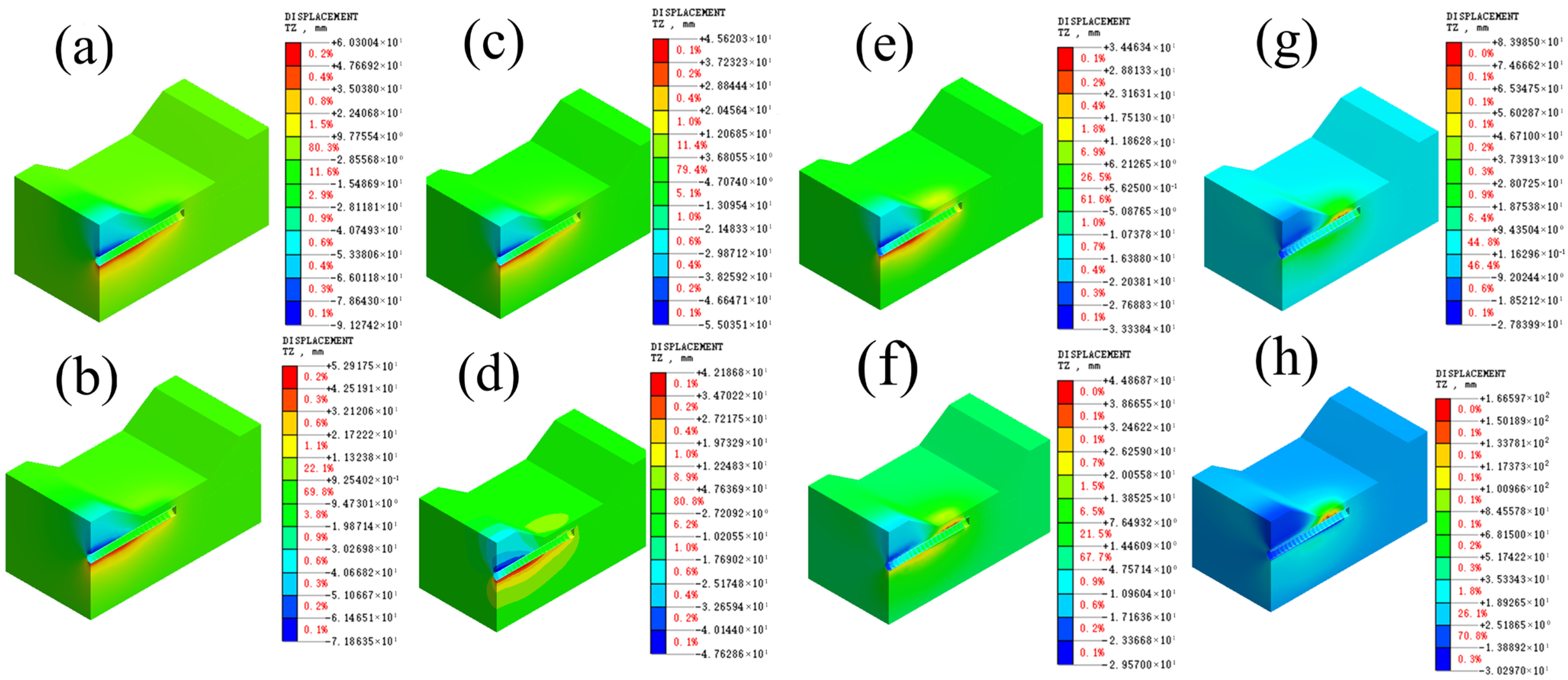
(2)
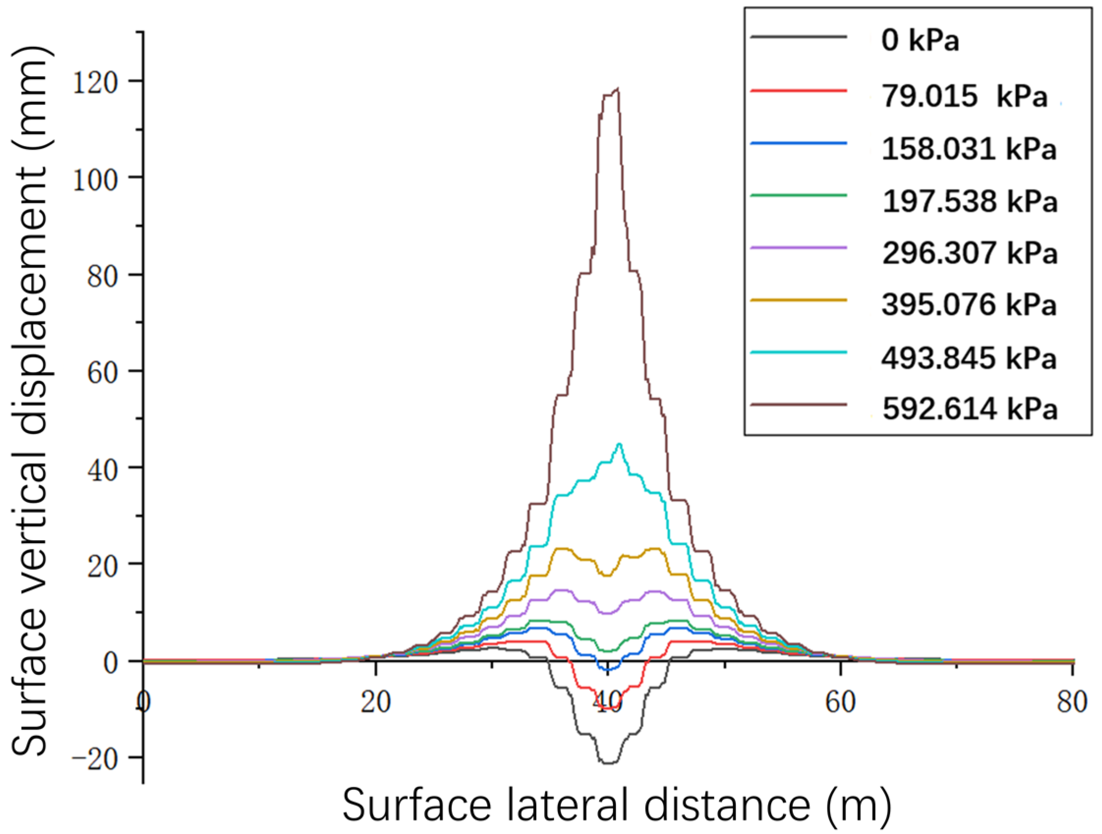
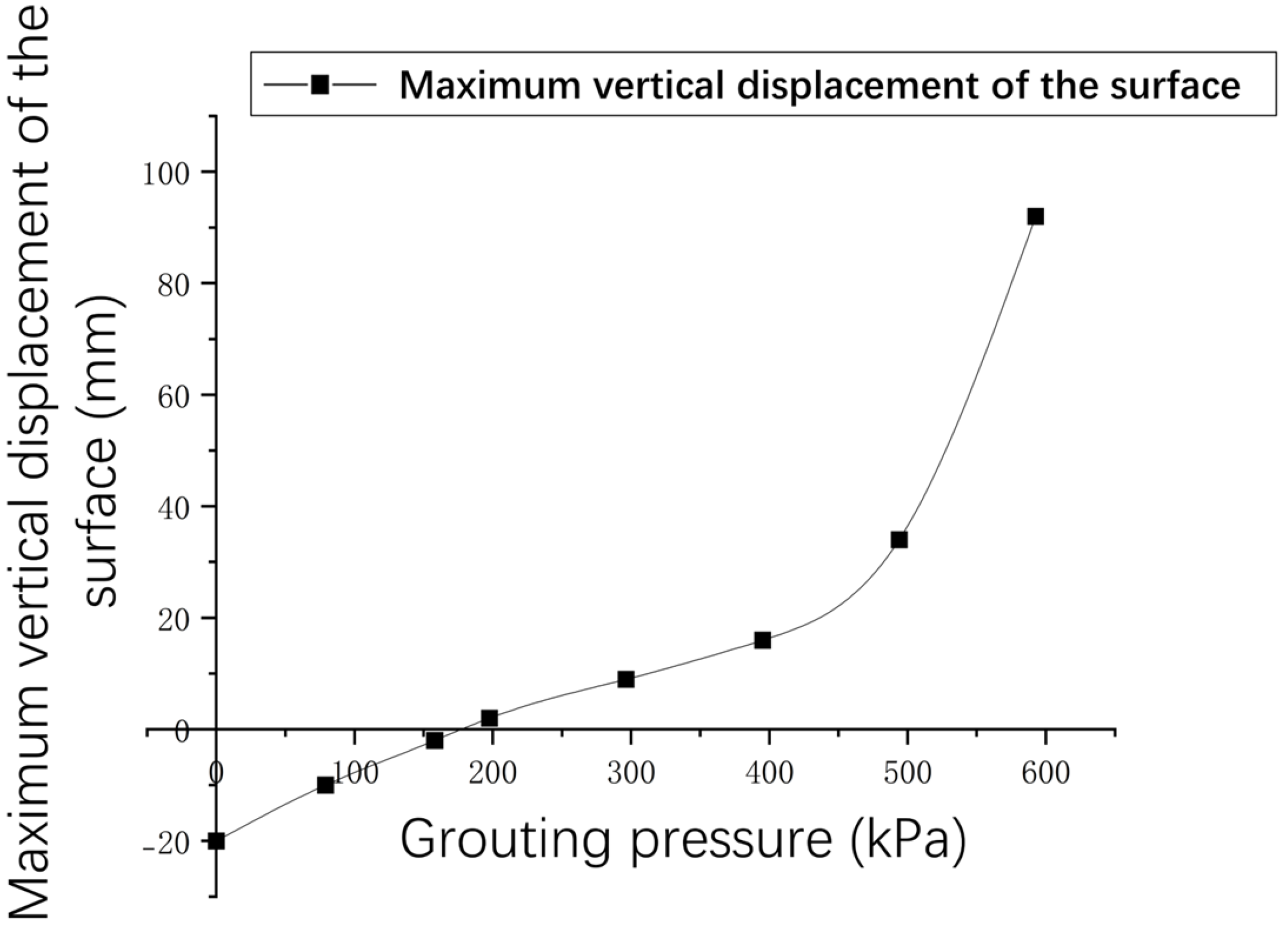
Numerical simulations were performed to calculate the working conditions of jacking-pipe grouting under different grouting pressures, and the surface displacement and deformation values under different grouting pressures were analyzed. As the jacking-pipe grouting pressure increases, the vertical displacement and deformation of the soil above the jacking pipe increases. When the jacking-pipe grouting pressure increased to 197.538 kPa, the displacement of the soil above the jacking pipe manifested itself as a bulge. The vertical displacement of the ground surface above the axial direction of the jacking pipe gradually decreases with the rising of the grouting pressure. When the jacking-pipe grouting pressure increases to 197.538 kPa, the manifestation of the maximum vertical displacement of the ground surface above the axial direction of the jacking pipe changes from settling to bulging.
(3)
This study revealed the influence law of grouting pressure on shallow buried river-crossing jacking-pipe grouting construction. Reasonable grouting pressure can effectively reduce formation loss and surface deformation. However, excessive jacking-pipe grouting pressure can produce surface bubbling and damage the jacking-pipe structure. Therefore, the critical grouting pressure is a major factor in the construction of similar projects. In construction practice, the critical grouting pressure is often derived from empirical estimates. The critical grouting pressure theory proposed in this study can provide an accurate reference value for similar projects. This will provide a theoretical basis and an adjustment program for the construction of similar projects. In the future, the research will be aimed at the IoT intelligent control platform, which will make the prediction and control of grouting pressure more convenient and reliable.

Author Contributions

Conceptualization, Z.Z.; Methodology, X.L. (Xiaopeng Li); Software, Y.H. and Xiang Li; Validation, X.L. (Xiaopeng Li); Formal analysis, Z.Z., X.L. (Xiang Li), L.W. and F.C.; Investigation, X.L. (Xiaopeng Li), X.L. (Xiang Li), L.W. and F.C.; Resources, X.L. (Xiaopeng Li) and L.W.; Data curation, Z.Z., Y.H., L.W. and F.C.; Writing—original draft, Y.H.; Writing—review & editing, Z.Z.; Visualization, Y.H., X.L. (Xiang Li) and F.C.; Project administration, X.L. (Xiaopeng Li); Funding acquisition, Z.Z. and L.W. All authors have read and agreed to the published version of the manuscript.

Funding

This study was funded by the Science and Technology Plan of Housing and Urban–Rural Construction in Anhui Province (2022-YF096), and the Science and technology development project (HYB20250019, HYB20250012).

Data Availability Statement

Data is contained within the article.

Conflicts of Interest

Author Xiaopeng Li was employed by the company First Engineering Co., Ltd. of CTCE Group. Author Lin Wei was employed by the company Chengji Railway Engineering Technology Co., Ltd. The remaining authors declare that the research was conducted in the absence of any commercial or financial relationships that could be construed as a potential conflict of interest.

References

  1. Wang, J.; Wang, K.; Zhang, T.; Wang, S. Key aspects of a DN4000 steel pipe jacking project in China: A case study of a water pipeline in the Shanghai Huangpu River. Tunn. Undergr. Space Technol. 2018, 72, 323–332. [Google Scholar] [CrossRef]
  2. Zhou, H.; Wang, H.; Huang, S.; Ma, B.; Ma, P. Key Techniques for the Ultra-Deep Large Flood Diversion Pipeline: A Case Study of Jinshui River Flood Diversion Project in Zhengzhou. Water 2025, 17, 13. [Google Scholar] [CrossRef]
  3. Wan, Y.; Khwaja, M.; Schultz, M.S.; Bold, G.; Simcoe, W. Tunneling to Manage Construction Impacts for Albany’s Beaver Creek Clean River Project, Albany, New York, 2021. In Proceedings of the Rapid Excavation and Tunneling Conference, RETC 2021, Las Vegas, NV, USA, 13–16 June 2021; Society for Mining, Metallurgy and Exploration: Las Vegas, NV, USA, 2021; pp. 61–68. [Google Scholar]
  4. Li, G.; Yang, C.; Pan, P.; Zhang, W. Record setting 3300-m distance by horizontal directional drilling of a 711-mm-diameter pipeline crossing the Yangtze River. J. Pipeline Syst. Eng. Pract. 2017, 8, 05016003. [Google Scholar] [CrossRef]
  5. Almeida Sousa, J.; Negro, A.; Matos Fernandes, M.; Silva Cardoso, A. Three-Dimensional Nonlinear Analyses of a Metro Tunnel in São Paulo Porous Clay, Brazil. J. Geotech. Geoenvironmental Eng. 2011, 137, 376–384. [Google Scholar] [CrossRef]
  6. Qian, D.; Jiao, H.; Li, Z.; Zhu, Y.; Liu, J.; Chen, Z.; Gao, X.; Liu, H.; Tao, B.; Xu, Z. Ground Settlement Law, Jacking Force Prediction, and Control Countermeasures for Large-Section Rectangular Pipe Jacking of National Highway Underpass. Sustainability 2023, 15, 12888. [Google Scholar] [CrossRef]
  7. Deng, L.; Chen, J.; Fan, W.; Li, Y.; Shi, L. The Dynamic Response Characteristics of a Water Transmission Pipe Crossing a Loess Fault Using a Large-Scale Shaking Table Test: A Case Study. Int. J. Geomech. 2024, 24, 05023012. [Google Scholar] [CrossRef]
  8. Zhou, S.; Ye, G.; Han, L.; Wang, J. Key Construction Technologies for Large River-Crossing Slurry Shield Tunnel: Case Study. J. Aerosp. Eng. 2021, 34, 04020118. [Google Scholar] [CrossRef]
  9. Ji, X.; Zhao, W.; Jia, P.; Qiao, L.; Barla, M.; Ni, P.; Wang, L. Pipe Jacking in Sandy Soil Under a River in Shenyang, China. Indian Geotech. J. 2017, 47, 246–260. [Google Scholar] [CrossRef]
  10. Wang, Z.; Wang, J.; Fan, D.; Liu, T.; Tan, Y. Parameters Analysis of Long-Distance Rectangular Pipe Jacking Underneath Beijing-Hangzhou Grand Canal. Tunn. Constr. 2024, 44, 159–167. [Google Scholar] [CrossRef]
  11. Wu, K.; Mu, L.; Hu, L.; Zhang, L. Numerical Analysis of Friction Reduction of Grouting in Long-Distance Pipe Jacking. Appl. Sci. 2025, 15, 1782. [Google Scholar] [CrossRef]
  12. Chen, P.; Liu, X.; Deng, Z.; Liang, N.; Du, L.; Du, H.; Huang, Y.; Deng, L.; Yang, G. Study on the pipe friction resistance in long-distance rock pipe jacking engineering. Undergr. Space 2023, 9, 173–185. [Google Scholar] [CrossRef]
  13. Qannadizadeh, A.; Shourijeh, P.T.; Lashkari, A. Laboratory investigation and constitutive modeling of the mechanical behavior of sand-GRP interfaces. Acta Geotech. 2022, 17, 4253–4275. [Google Scholar] [CrossRef]
  14. Shimada, H.; Khazaei, S.; Matsui, K. Small diameter tunnel excavation method using slurry pipe-jacking. Geotech. Geol. Eng. 2004, 22, 161–186. [Google Scholar] [CrossRef]
  15. Kasper, T.; Meschke, G. On the influence of face pressure, grouting pressure and TBM design in soft ground tunnelling. Tunn. Undergr. Space Technol. 2006, 21, 160–171. [Google Scholar] [CrossRef]
  16. Ye, F.; Yang, T.; Mao, J.; Qin, X.; Zhao, R. Half-spherical surface diffusion model of shield tunnel back-fill grouting based on infiltration effect. Tunn. Undergr. Space Technol. 2019, 83, 274–281. [Google Scholar] [CrossRef]
  17. Lyu, H.; Sun, W.; Shen, S.; Arulrajah, A. Flood risk assessment in metro systems of mega-cities using a GIS-based modeling approach. Sci. Total Environ. 2018, 626, 1012–1025. [Google Scholar] [CrossRef] [PubMed]
  18. Ye, F.; Li, S.; Xia, T.; Shu, E.; Han, B.; Zhang, C. Compaction-fracture diffusion model for backfill grouting of shield tunnels in low permeability strata. Chin. J. Geotech. Eng. 2023, 45, 2014–2022. [Google Scholar]
  19. Soga, K.; Au, S.K.A.; Jafari, M.R.; Bolton, M.D. Laboratory investigation of multiple grout injections into clay. Geotechnique 2004, 54, 81–90. [Google Scholar] [CrossRef]
  20. Zhang, D.; Fang, Q.; Lou, H. Grouting techniques for the unfavorable geological conditions of Xiang’an subsea tunnel in China. J. Rock Mech. Geotech. Eng. 2014, 6, 438–446. [Google Scholar] [CrossRef]
  21. Liu, J.; Cheng, H.; Cai, H.; Wang, X.; Feng, D. Design and Analysis of Grouting Pressure in Slurry Pipe Jacking Based on the Surrounding Soil Stability Mechanical Characteristics. Geofluids 2022, 2022, 4697730. [Google Scholar] [CrossRef]
  22. Shimada, H.; Sasaoka, T.; Khazaei, S.; Yoshida, Y.; Matsui, K. Performance of Mortar and Chemical Grout Injection into Surrounding Soil When Slurry Pipe-jacking Method is Used. Geotech. Geol. Eng. 2006, 24, 57–77. [Google Scholar] [CrossRef]
  23. Khazaei, S.; Shimada, H.; Kawai, T.; Yotsumoto, J.; Matsui, K. Monitoring of Over Cutting Area and Lubrication Distribution in a Large Slurry Pipe Jacking Operation. Geotech. Geol. Eng. 2006, 24, 735–755. [Google Scholar] [CrossRef]
  24. Yazdani, M.; Majdi, A. Predicting the Critical Grout Pressure in Anisotropic Rocks Based on the Maximum Energy Release Rate Criterion. Int. J. Geomech. 2024, 24, 04023273. [Google Scholar] [CrossRef]
  25. Li, C. Simplified Algorithm for Grouting Pressure and Grouting Quantity in Shield Construction. Int. J. Civ. Eng. 2020, 18, 419–428. [Google Scholar] [CrossRef]
  26. Jie, L. Analysis of the Mud Escaping of HDD and R&D for Preventing Mud Escaping Software. Master’s Thesis, China University of Geosciences, Wuhan, China, 2009. (In Chinese). [Google Scholar]
  27. Ma, M.; Han, L.; Wu, Y.; Li, Q.; Zhang, Y. Behavioral Investigations of Three Parallel Large Reinforced Concrete Circular Pipes with the Construction of Pipe Jacking. Appl. Sci. 2023, 13, 8901. [Google Scholar] [CrossRef]
  28. Ren, D.; Xu, Y.; Shen, J.; Zhou, A.; Arulrajah, A. Prediction of Ground Deformation during Pipe-Jacking Considering Multiple Factors. Appl. Sci. 2018, 8, 1051. [Google Scholar] [CrossRef]
  29. Ma, X.; Zou, Y.; Li, X.; Hong, B. Centrifugal Model Test on the Influence Mechanism of Pipe Jacking Grouting Pressure on Formation Settlement. Adv. Eng. Sci. 2021, 53, 110–117. [Google Scholar] [CrossRef]
  30. Li, C.; Liang, Q.; Ma, X. Study on grouting pressure in shield tunnel construction of Lanzhou subway crossing the Yellow River section. Railw. Eng. 2014, 8, 52–54. (In Chinese) [Google Scholar] [CrossRef]
  31. Xu, B.; Dong, S.; Yin, S.; Li, S.; Xu, Y.; Dai, Z. Analysis of Crack Initiation and Propagation Thresholds of Inclined Cracks under High-Pressure Grouting in Ordovician Limestone. Energies 2021, 14, 360. [Google Scholar] [CrossRef]
  32. Yang, X.; Liu, Y.; Yang, C.; Chen, Y. Research on the Slurry for Long-Distance Large-Diameter Pipe Jacking in Expansive Soil. Adv. Civ. Eng. 2018, 2018, 9040471. [Google Scholar] [CrossRef]
Figure 1. The synchronized grouting jacking process.
Buildings 15 02359 g001
Figure 2. The surface leakage mechanism.
Buildings 15 02359 g002
Figure 3. Force analysis model: (a) forces of unit; (b) plane state of stress.
Buildings 15 02359 g003
Figure 4. Project site: (a) underground pipe network for drainage and flood control; (b) plan of the project.
Buildings 15 02359 g004
Figure 5. Numerical simulation model for jacking pipe with mud–water balance: (a) simulation model; (b) equivalent layer.
Buildings 15 02359 g005
Figure 6. Numerical simulation assumptions: (a) frontal support pressure; (b) pipe–soil friction force; (c) grouting pressure.
Buildings 15 02359 g006
Figure 7. Clouds of soil vertical displacement under different grouting pressures: (a) 0 kPa; (b) 79.015 kPa; (c) 158.031 kPa; (d) 197.538 kPa; (e) 296.307 kPa; (f) 395.076 kPa; (g) 493.845 kPa; (h) 592.614 kPa.
Buildings 15 02359 g007
Figure 8. Vertical displacement plot of the ground surface under different grouting pressures.
Buildings 15 02359 g008
Figure 9. Vertical displacement of the ground surface in the axial direction of the jacking pipe at different grouting pressures.
Buildings 15 02359 g009
Figure 10. Relationship between grouting pressure and maximum vertical displacement of the ground surface.
Buildings 15 02359 g010
Figure 11. Sensitivity analysis of critical grouting pressure P m : (a) the cohesive force c ; (b) the angle of internal friction φ ; (c) the thickness of overburden h s .
Buildings 15 02359 g011
Table 1. Calculated parameters and results.
Calculated
Parameters
ValueCalculated ResultsValue
c 40 kPa K 0.733
φ 15.5° L 27.66
h s 3 m M 77.09
ρ s 1.922 kg/m3 Δ 134,811.105
γ s a t 19.22 kg/m3 P m 197.538
Table 2. The material property parameters.
Parameter TypeElastic
Modulus
E/(MPa)
Poisson’s
Ratio
μ
Volumetric Weight
γ/(kN/m3)
Cohesive Force
c/(kPa)
Angle of Internal Friction
φ/(°)
Fill8.00.2718.001010.0
Silty chalky clay3.20.2717.526.25.8
Clay11.90.2519.2269.116.9
Silty clay11.30.2519.2239.315.5
pipe sheet28,0000.223.0--
Jacking machine’s shell206,0000.378.5--
Table 3. Grouting pressure calculation condition.
Grouting
Pressure   Ratio   p
Grouting Pressure
P (kPa)
Grouting
Pressure   Ratio   p
Grouting Pressure
P (kPa)
001.5296.307
0.479.0152.0395.076
0.8158.0312.5493.845
1.0197.5383.0592.614
Table 4. The theoretical calculation process.
Parameters h s c φ K L M P m
Variant
c
3.020.0 15.50.73327.6638.54539,253.553117.085
3.040.0 15.50.73327.6677.090134,811.105197.538
3.060.0 15.50.73327.66115.636287,251.475277.886
3.080.0 15.50.73327.66154.181496,574.662358.205
3.0100.0 15.50.73327.66192.726762,780.666438.510
3.0150.0 15.50.73327.66289.0891,677,158.000639.252
3.0200.0 15.50.73327.66385.4522,947,052.942839.981
3.0250.0 15.50.73327.66481.8154,572,465.4911040.704
3.0300.0 15.50.73327.66578.1786,553,395.6471241.424
3.0400.0 15.50.73327.66770.90411,581,808.7801642.861
3.0500.0 15.50.73327.66963.63018,032,292.3412044.294
3.0600.0 15.50.73327.661156.35725,904,846.3302445.727
Variant
φ
3.040.05.00.91327.6679.696135,312.179179.673
3.040.010.00.82627.6678.785137,740.448188.310
3.040.015.00.74127.6677.274135,308.454196.710
3.040.020.00.65827.6675.175128,440.189204.893
3.040.025.00.57727.6672.505117,890.351212.859
3.040.030.00.50027.6669.282104,642.083220.586
Variant
h s
1.040.015.50.7339.2277.090120,652.165172.937
2.040.015.50.73318.4477.090127,667.322185.257
3.040.015.50.73327.6677.090134,811.105197.538
4.040.015.50.73336.8877.090142,083.514209.782
5.040.015.50.73346.1077.090149,484.549221.991
6.040.015.50.73355.3277.090157,014.210234.169
7.040.015.50.73364.5477.090164,672.497246.317
8.040.015.50.73373.7677.090172,459.410258.438
9.040.015.50.73382.9877.090180,374.949270.534
10.040.015.50.73392.2077.090188,419.114282.605
Disclaimer/Publisher’s Note: The statements, opinions and data contained in all publications are solely those of the individual author(s) and contributor(s) and not of MDPI and/or the editor(s). MDPI and/or the editor(s) disclaim responsibility for any injury to people or property resulting from any ideas, methods, instructions or products referred to in the content.

