Article

Structural Failures in an Architectural Heritage Site: Case Study of the Blagoveštenje Monastery Church, Kablar, Serbia

Department of Architectural Technologies, Faculty of Architecture, University of Belgrade, 11000 Belgrade, Serbia
*
Author to whom correspondence should be addressed.
Buildings 2025, 15(13), 2328; https://doi.org/10.3390/buildings15132328
Submission received: 18 May 2025 / Revised: 27 June 2025 / Accepted: 30 June 2025 / Published: 2 July 2025
(This article belongs to the Special Issue Advanced Research on Cultural Heritage)

Abstract

Authenticity is a core principle in conservation guidelines and a key goal of heritage preservation, especially in Serbia, where many aging objects face ongoing deterioration. The subject of this study is the church within the Blagoveštenje Monastery complex in the Ovčar-Kablar gorge, built using stone from a local quarry at the beginning of the 17th century. The inclination of the structure, observed as progressively increasing over the centuries, raises important concerns regarding its stability. This research focuses on identifying the underlying causes of this phenomenon in order to support its long-term preservation. The methods used the study are long-term in situ observations including analysis, geodetic research, 3D laser imaging, geophysical, geological, archaeological research, evaluation of current condition, determination of structural failures and their cause and monitoring the structural behavior of elements. All methods were carried out in accordance with the definition of rehabilitation measures and the protection of masonry buildings. The main contribution of this study is identifying that the church’s inclination and deviation result from the northern foundation resting on weaker soil and a deeper rock mass compared to the southern side. The research approach and findings presented in this paper can serve as a guide for future endeavors aimed at identifying the causes of deformations and the restoration and structural rehabilitation of masonry buildings as cultural heritage.

1. Introduction

This paper presents a multidisciplinary approach to analyzing the existing problems in the church within the Blagoveštenje Monastery in Kablar, to prevent further deterioration.
The basic hypothesis of this paper is that rehabilitation of the church is possible by applying appropriate construction measures in accordance with conservation requirements. These measures would stop the church’s inclination, stabilize it, and prevent further deformations of the structural elements, maintaining the authentic appearance. Maintaining authenticity is a fundamental principle in most conservation guidelines and serves as the primary objective of heritage preservation [1]. The concept of authenticity, as outlined in the Nara Document on Authenticity (1994) [2], plays a crucial role in cultural heritage research, conservation practices, and the selection criteria for the World Heritage List. This document defines the main aspects of and assessment criteria for authenticity [2].
The aim of this study is to discover the causes of inclination and deviation in the masonry structure of the church in accordance with the guidelines of authenticity.
The objectives of the research are the following:
  • Undertake active research of the locality that will contribute to the protection and preservation of the entire monastery complex;
  • Improve knowledge about the importance of preserving historical buildings, and their potential, to reconstruct and pass on cultural heritage;
  • Discover the causes of the structural failure of the church and its inclination;
  • Determine the construction measures needed to prevent further damage during the rehabilitation, thus preventing structural failures as well;
  • Systematize knowledge on the causes of the church’s damage, and recommend construction measures for preservation, rehabilitation, and the prevention of further deterioration;
  • Make the research results available to professionals who deal with similar problems.
The research methodology consists of analysis, systematization of data from the literature, and in situ observation of the Blagoveštenje Monastery. The methods of conservation were determined in accordance with the analysis and evaluation of the object.
This would imply the importance of studying cause-and-effect relationships between the condition on the site itself and the behavior of the church and elements of the structure. This would result in defining rehabilitation criteria and conservation measures based on the prior in situ analysis. The preparation of a restoration project would prevent further inclination and occurrence of new deformations in the church. During diagnostics and reconstruction, a static analysis of the structure and a check of the stress states are required. This paper does not cover these analyses, as it was determined in advance that the cracks were not caused by stress conditions.
The methodology also includes monitoring cracks in the future through the installation of three-axis dilatometers to observe new deformations and the progression of existing ones.
The goal of this study is to determine the cause of the wall’s inclination, as well as its impact on the structural elements of the church.

Literature Review

The purpose of structural interventions in relics is to improve the overall preservation of the future and the safeguarding of the historical information they hold [3]. Historical monuments and relics are defined in accordance with typological, structural, constructional, functional, aesthetic, formal, historical, and symbolic values. These features are significant for a conservation project in terms of selecting an appropriate critical methodology to evaluate the outcomes of the project objectively [4].
The crucial role of adequate prevention and rehabilitation is played by accurately analyzing all structural failures and damage to the building [5,6]. Effective architectural heritage preservation requires a multidisciplinary approach integrating complementary research and activities, which can be divided into material, geometry, morphology, actions, damage and alterations, and history [7].
To further preserve buildings with a masonry-bearing structure, the most important thing is to evaluate its structural stability. The methods used in the diagnostic testing of masonry building structures are divided into destructive, semi-destructive, and non-destructive methods [8,9]. In recent decades, methods for diagnosing the current condition of masonry structures have been improved, emphasizing non-destructive (NDT) or moderately destructive testing (MDT) methods. The NDT methods that are most commonly used during interventions on architectural heritage are Digital Image Processing (DIP), Photogrammetry (P) [10] and Stereo photogrammetry (SP), Laser levelling (LL), Ambient Vibration Testing (AVT), Infrared Thermography (IRT) [11], ultrasound testing and underground mapping analysis using Ground-penetrating radar (GPR) [12], the sonic pulse velocity method, and operational modal analysis (OMA) [13,14,15]. The combination of the NDT methods with the visual assessment method can provide reliable information about the church’s condition, which is crucial for forming conclusions and proposing intervention measures. The reason for such an integrated approach stems from the fact that in certain situations, only a visual inspection of the surfaces of masonry elements is not enough. However, it is necessary to analyze the structure within the given elements, that is, under the surfaces, all in order to identify existing and potential problems within masonry structures [16].
To comprehensively assess the building’s condition, the investigation begins with preliminary in situ testing and a survey to evaluate its geometric characteristics and visible damage. In situ testing is carried out to identify the types of deformations in the church and to determine their potential causes. The in situ method is carried out along with literature-based research to create a precise picture of the historical context and an overview of the condition of the church through the ages. Observing and analyzing the cracks usually reveals the past behavior of the masonry structure and leads to the areas of degradation on the building’s external finish, which can be analyzed to confirm the theory of past behavior [17].
Nowadays, analysis has three main steps: a survey of the geometry, a study of the crack pattern and the masonry stratigraphy (changes in the surface materials and textures), and documentary research [18]. Also, load capacity testing requires information on the strength of the structure’s materials, the existing loading and its constraints, and the expected loadings at failure [19].
Precise observations of cracks and their geometry can indicate specific causes of deformations and potential destruction mechanisms. In places where a characteristic arrangement of cracks is observed and where there is an assumption that the cracks will develop, measurements are taken. These measurements track the displacement and deformation of the masonry structure over time.
By analyzing the current condition, three types of cracks in masonry wall elevations can be identified. The first type are cracks in a diagonal direction, which go from the center of the object to the foundations, i.e., the place of the subsidence of the object. The cause of these cracks is most often found in the foundations themselves. The second type are vertical cracks caused by poor material quality or thermal changes. Vertical cracks that spread from the bottom to the top may indicate that the wall is moving outwards or rotating on eccentrically loaded foundations. Cracks can also occur during the phased construction of the building [20].
The objects of this study are vertical deviations in the church, their monitoring, and an investigation of the causes of inclination. Masonry constructions exhibit poor structural performances and are prone to substantial damage [21]. The causes of these problems and the possibility of progressive inclination, as well as other changes in the elements of the supporting structure of the church, are as follows [22,23]:
  • The weight of the masonry structure;
  • Earth pressure: Mainly governed by the nature and the compaction of the artificial filling, excavations, refilling compaction, rainwater effects, the live loads, and seismic motion;
  • Hydraulic action: Increase in unit weight due to saturation, smoothing of the stone blocks’ joints, hydrostatic pressure behind the low-permeability parts of the wall, and natural degradation of the stone blocks with a loss of mass;
  • Military actions such as bombardments, and ground blasting during the construction of tunnels;
  • Earthquakes, as seismic action.
There are three main categories of structural problems in architectural heritage buildings [23,24]: geometrical, mechanical, and those caused by the unfavorable effects of natural physicochemical agents.
Geometrical problems refer to structural form changes without the failure of structural components, such as displacement, rotations, barreling, and inclination, and are caused by intense soil pressure and the effects of seismic movements.
Mechanical problems are related to strains and failures of the structural components without any form changes but with the existence of small cracks, breaks, detachments of stones, inclinations, etc. These failures cause specific local weaknesses, raising awareness of the structural strength of the structure—the capability of the structure (the wall) to respond to increased transient loading (hydrostatic pressures from heavy rains, earthquakes, etc.). Moreover, failures are mainly caused by significant compressive and/or tensile stresses developing on the wall mass due to various loadings.
Problems caused by the unfavorable effects of natural physicochemical agents result in cracks, a loss of mass, efflorescence of the stone, mortar leach, etc.
Proper rehabilitation of damaged historical buildings requires an understanding and knowledge of the problems in their foundations [24]. Uneven load distribution under the foundations causes differential subsidence, which leads to cracks and distortion of the entire structure [23]. In addition, bearing capacity inconsistencies can also be influenced by different dimensions and shapes of the foundation or uneven foundation depth [25].
The reconstruction and rehabilitation of any structural element and its return to its original state is ineffective and will not contribute to the longevity of the monument unless the causes that led to the problem, and which continue to operate, are removed [26].
It is important to consider the appearance of cracks and inclinations on the building throughout history, as well as to examine the soil on which the building was founded, to obtain reliable data about the design of the original building [19]. A non-destructive monitoring and testing program should be implemented to provide continuous insights into the current structural condition of the building [27].

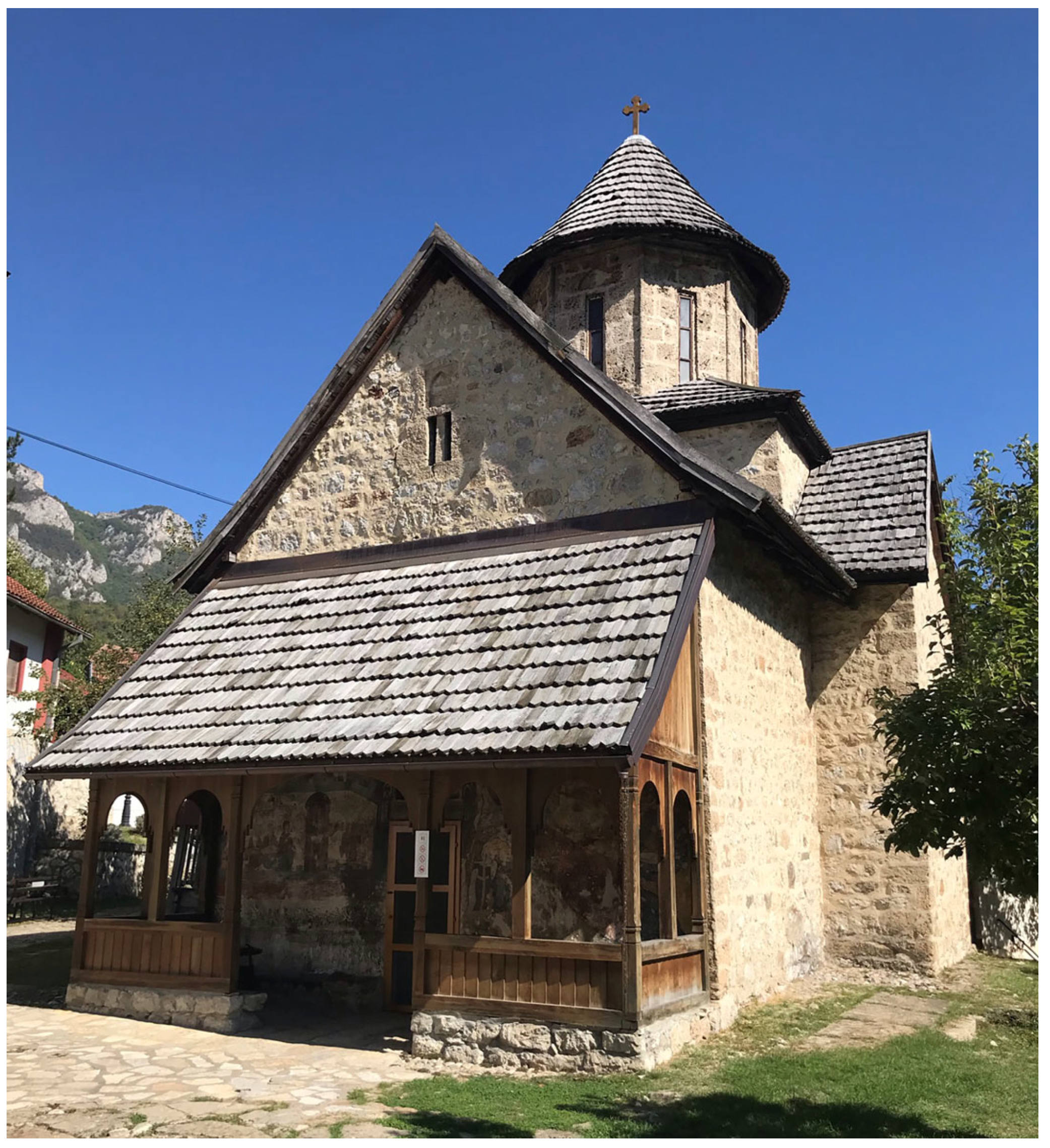
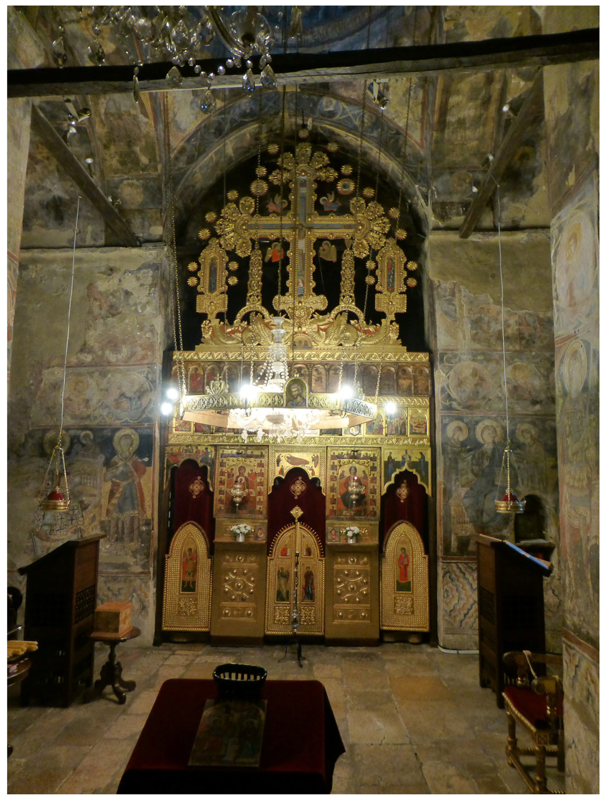
2. Historical Review and the Results of the Previous Restoration Works

The church of the Blagoveštenje Monastery is dedicated to the Annunciation of the Blessed Virgin Mary and is one of the most significant cultural monuments within the Ovčar-Kablar monasteries situated on the Kablar mountain near the City of Čačak in western Serbia (Figure 1).
Given its architecture, wall paintings, and iconostasis (Figure 2), it is representative of a monastery built at the beginning of the 17th century. The church with a dome was built as an inscribed cross, a characteristic of the Byzantine style and the “Raška school” [28]. The church was built as a single nave with a dome on an octagonal tambour, with three bays, side choirs, and a semicircular altar apse.
The main building material is rough-hewn blocks made from local stone quarry bound with lime mortar. Only the tambour that carries the dome was built of carefully and beautifully carved hewn blocks of the same type of natural stone, which were properly arranged (Figure 3). The facade was originally plastered and painted [28].
On the west side of the church, there is a porch lower than the nave’s height. The porch is separated from the church gate by exquisitely executed arcades and wooden columns and its single-pitched roof, which stands out from the usual solutions of the Raska style. Archaeological research has established that the whole church was built at the same time and that there are no traces of older foundations [29].
Figure 3. South elevation of the church; existing conditions in 1967 [30].
Buildings 15 02328 g003
In the inscription above the entrance door, there is a text which indicates 1601 as the year of construction. Another record reveals that during 1632–1633, the iconostasis was completed and the frescoes were vividly painted, and today the greatest achievements in Serbian fresco painting from that period are present [30]. The church was rebuilt and covered with shingles for the second time in 1644 when it is assumed that a new apse was built because the old one collapsed for an unknown reason, and it is still unpainted [29]. The re-roofing works were carried out in 1809.
A large number of structural failures occurred as a result of various tremors, earthquakes, and other harmful effects during the occupation of Serbia by the Turks. Observations in 1820 noted that the altar apse was rebuilt since the previous apse was cracked and collapsed [31].
The church was rebuilt and re-roofed several times. This occurred after ground blasting and demolition of the railway bridge in the 1930s. It was also repaired after the German bombing during the Second World War. Additional reconstruction took place after the occupiers retreated and destroyed bridges and parts of the natural landscape in the area.
In 1946 and 1947, during the construction of the “Ovčar Banja” hydroelectric power plant on the West Morava River, blasting during the construction of two tunnels near the monastery caused damage to the monastery’s buildings. Numerous cracks appeared on the church’s facade, and there was a significant spreading of the arches on the piers, dome supports, because of the progression of existing structural failures [32].

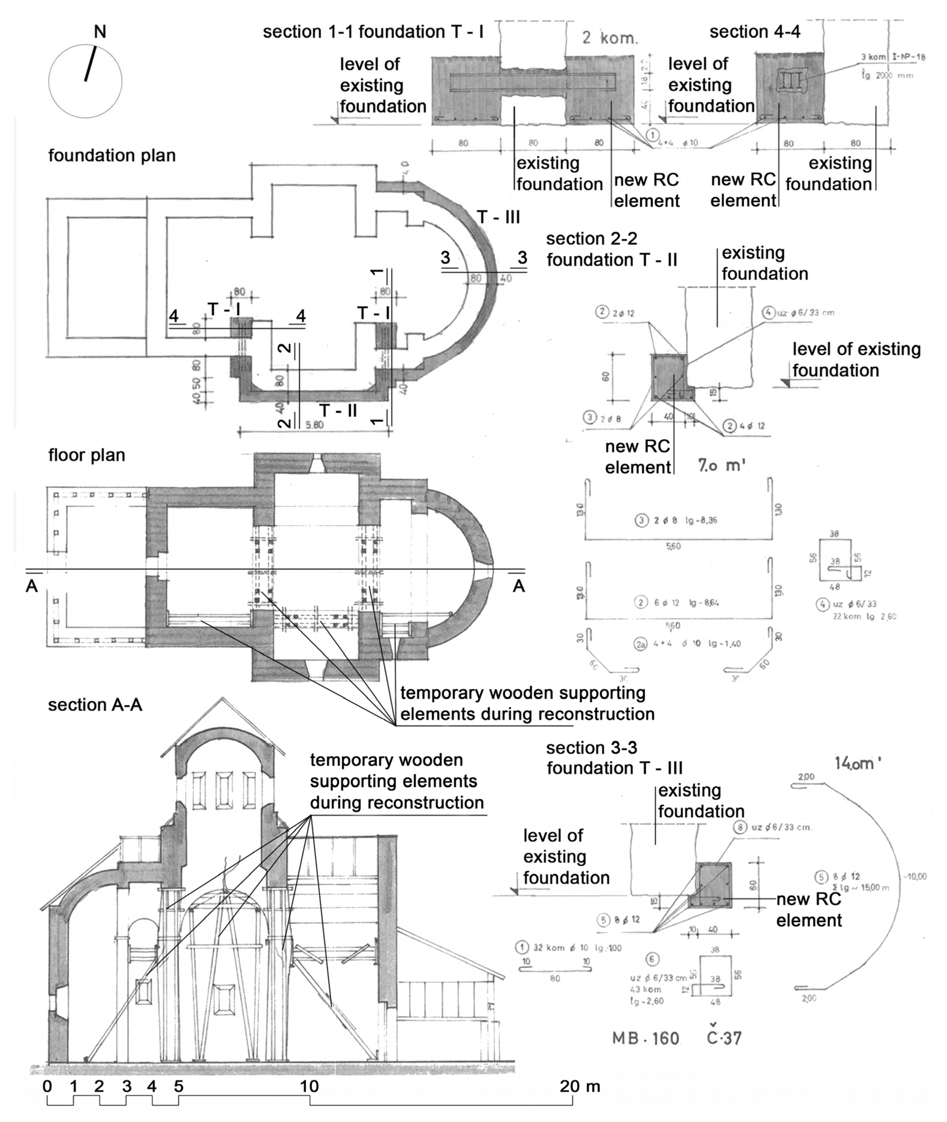
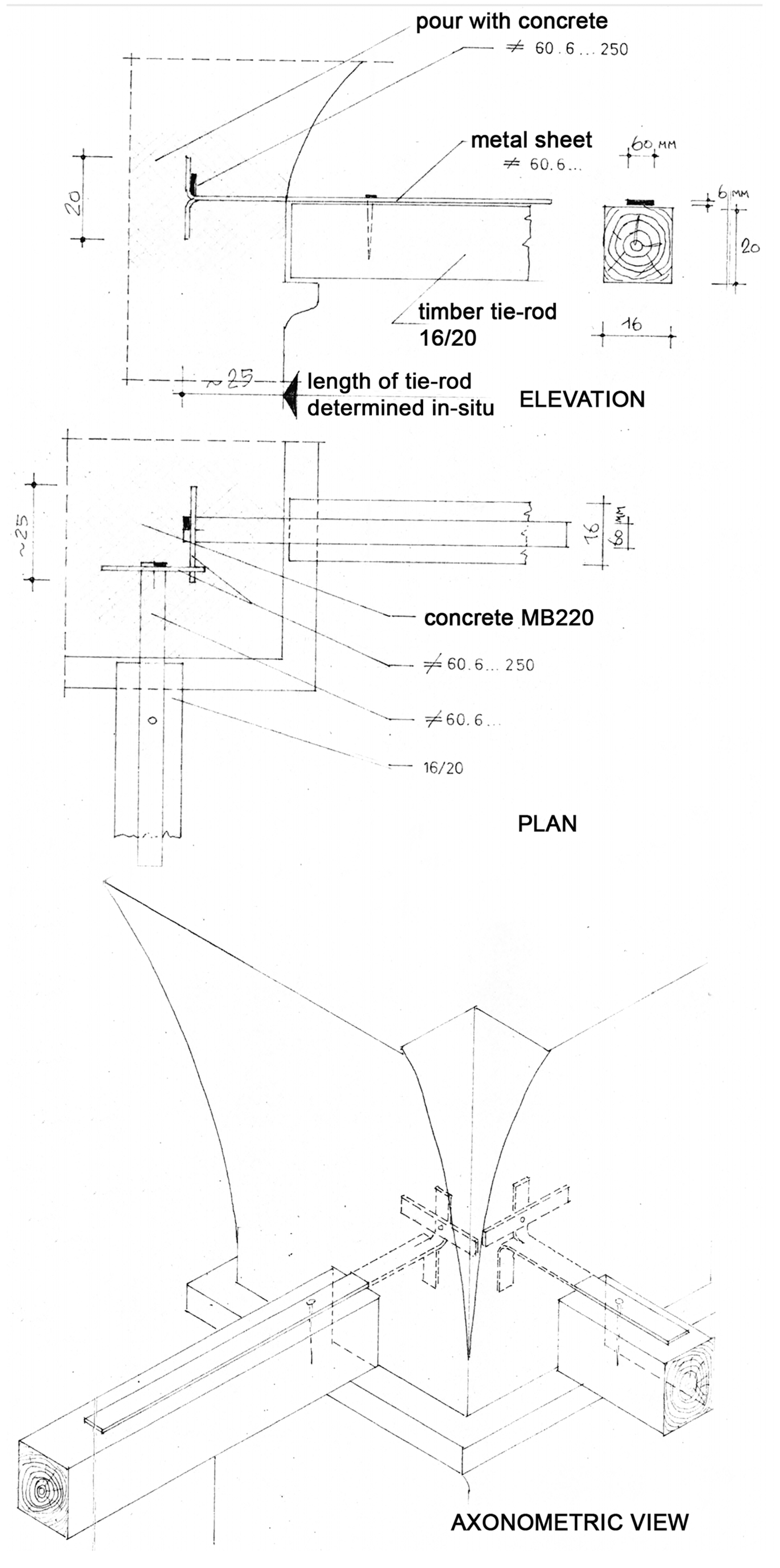
3. Previous Works on the Restoration of the Church

Based on the literature review, it appears that many renovations were carried out from the 17th to the 20th century (Table 1). The in situ observation was carried out using insights and analysis of the renovations described in the literature. The literature states that the church was reconstructed 40 years after its construction, and the altar apse was rebuilt [29]. This means that the first reconstruction was carried out in 1644.
Between the two world wars, reinforcement was carried out in the foundation zone in the form of a reinforced concrete (RC) ring, 25 cm wide and 40 cm high, around the entire church. This RC ring is positioned on the lower level of the present foundation level of the church (Figure 4) [32]. Then, large steel weights (ø60 mm) were placed under the mid-level cornice along the length of the church from the west wall to the wall between the nave and the east aisle, essentially along the plane of the altar partition. A project from the 1970s shows that another round of strengthening was carried out around the southern choir and the altar apse all the way to the northern choir, above the original strengthening of the foundations [32,33]. The measures implemented, including strengthening of the existing masonry foundations using RC, represent the principles used to this day in accordance with the technical measures of protection for architectural heritage objects. Furthermore, the designers decided to remove the steel weights after the strengthening above the foundation was complete (Figure 5). The next phase was the removal of steel reinforcements in the form of tie-rods, which extended from the western wall to the wall between the nave and the eastern aisle (along the plane of the altar partition) at the level of the mid-level cornice (Figure 5). During this restoration, RC ring beams were designed and installed on the church’s walls, which was confirmed by exploration pits when a part of the wooden vault in the western passage was removed.Instead of two longitudinal steel beams, four wooden beams were reinforced with steel sheets within the western span of the church in the north–south direction and four were installed under the sub-dome arches [32,33]. The tie-rod under the sub-dome arch in the southern part of the building was pulled out of its bearing and did not bear any of the impact.
To verify the existence of the reinforcements, three exploration pits, marked as 1, 2, and 4, were excavated (Figure 15). The pits next to the foundation on the north and south sides revealed three reinforcements. One reinforcement is certainly from the period between the two world wars, the second in 1969–1970, and the third cannot be specified since this information was not found in the literature. Historical monuments are often reinforced using traditional methods, including the integration of timber elements, bond beams, steel tie rods, anchors, and corner keys, the construction of new adobe buttresses, and the selective replacement of damaged or deteriorated masonry units [34]. The same principles were applied to the church in 1966, and during the first stage of the works carried out, a supporting structure was placed in the under-dome area and RC reinforcements were installed at the church’s base [32,33]. Because of the cracks in the church, steel tie-rods were placed in the upper zone anchored in the perimeter walls. This did not secure the central space of the church, that is, the dome itself is not strengthened. The tie-rods pass through the pilasters, the supports of the dome, without connecting to each other above the supports of the arches (Figure 6).
Reinforcement around the church’s foundation, on the outside, was carried out using a concrete ring, 50–60 cm wide and 60 cm high, strengthening the building to a greater extent and preventing further movement in its structure (Figure 4) [33].
In the first phase, a supporting structure was placed in the under-dome space, and reinforcements were made at the church’s foundation level (Figure 4). A chronological overview of all interventions in the building is shown in Table 1.
Through the literature research, observation of exploration pits, and in situ inspection, our analyses confirmed that subsidence occurred on the northern part of the church, and that is extremely large compared to the southern part, and cracks appeared on the arches under the dome (Figure 7), but the fewest were on the northern arc.
Large cracks in the southern part of the church were observed even before. The formation of cracks is common in places where the structure subsides; for this reason, most interventions were in the southern part of the building.

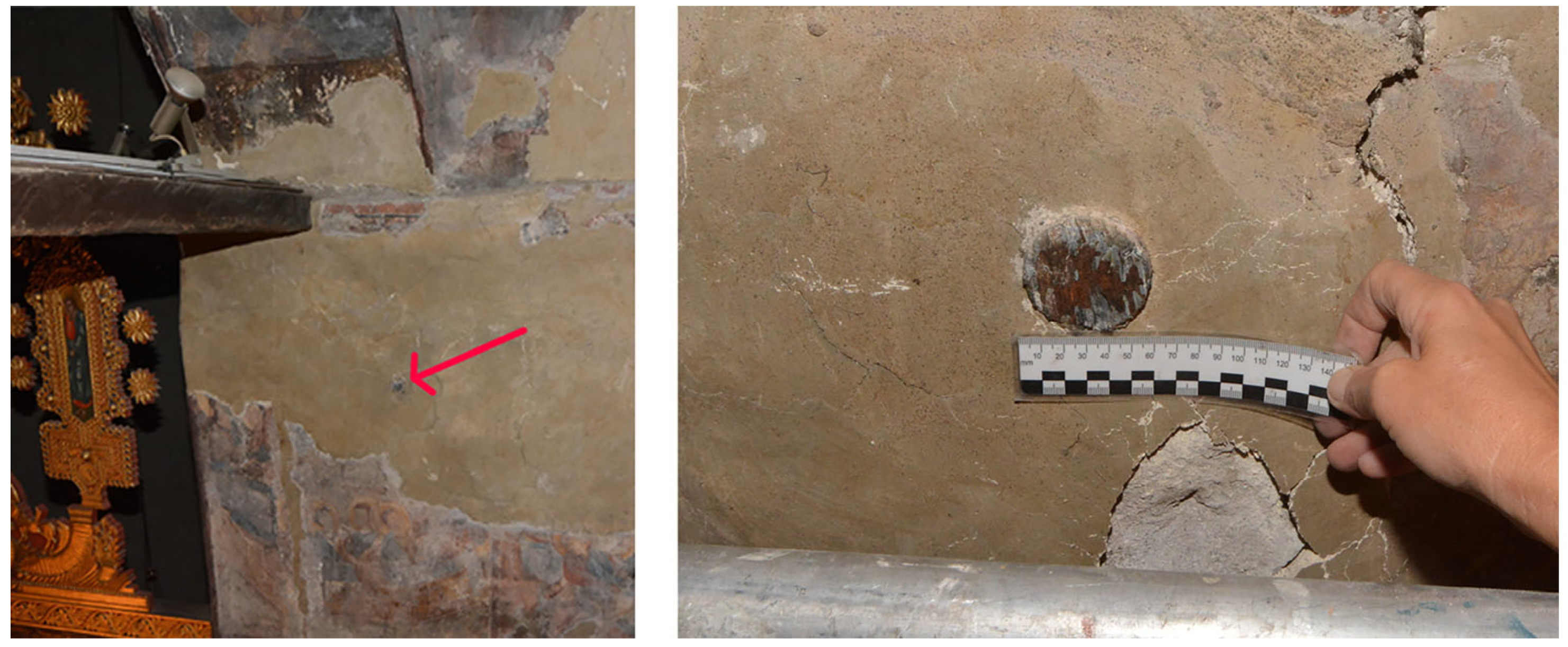
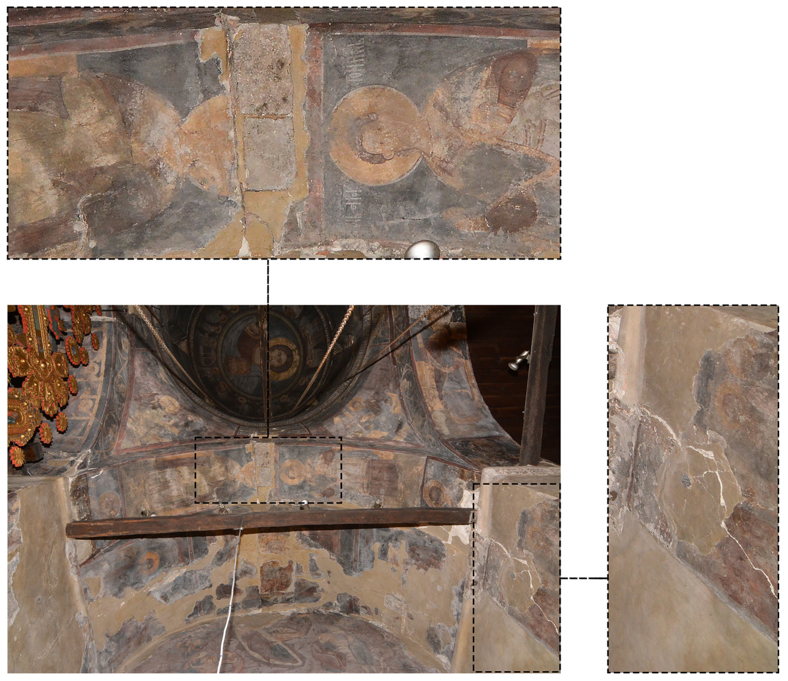
4. Results of Site Investigation

Construction observations and an in situ inspection confirmed the cracks on the church, as well as its deviation from the vertical axis and inclination towards the north side. This could result from the foundations and the heterogeneous soil on which the church was founded. The southern part is oriented towards the slope towards the West Morava River, while the northern part is oriented towards the hill. Based on the configuration of the terrain, it could be assumed that the foundations are worse towards the slope, that is, on the southern side, where a large number of cracks are present. However, previous researchers revealed the church’s deviation from the vertical plane and its inclination towards the north.
An expert interdisciplinary team consisting of structural engineers, archaeologists, conservators, geodetic engineers and geologists, conducted the in situ inspection in the period from 2020 to 2022.

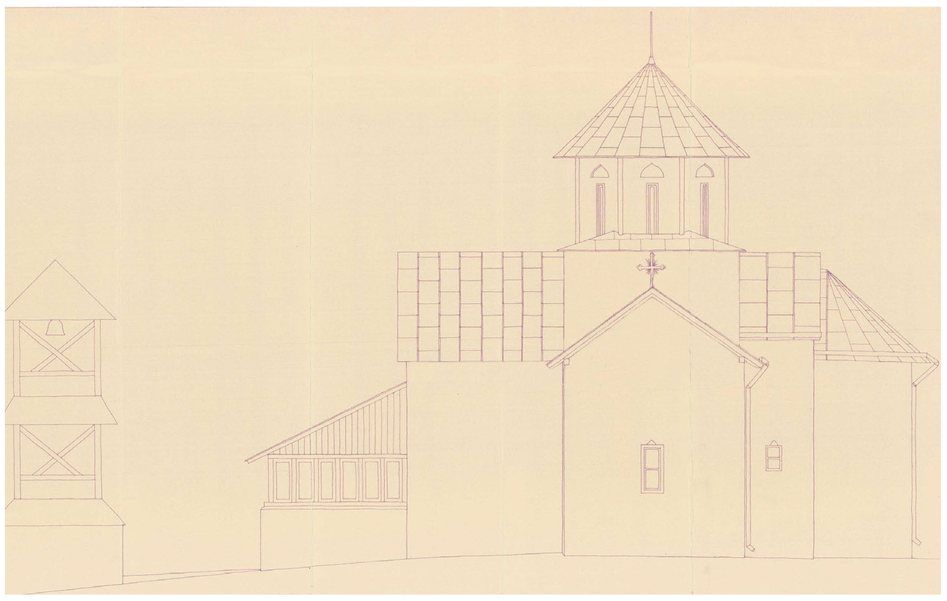
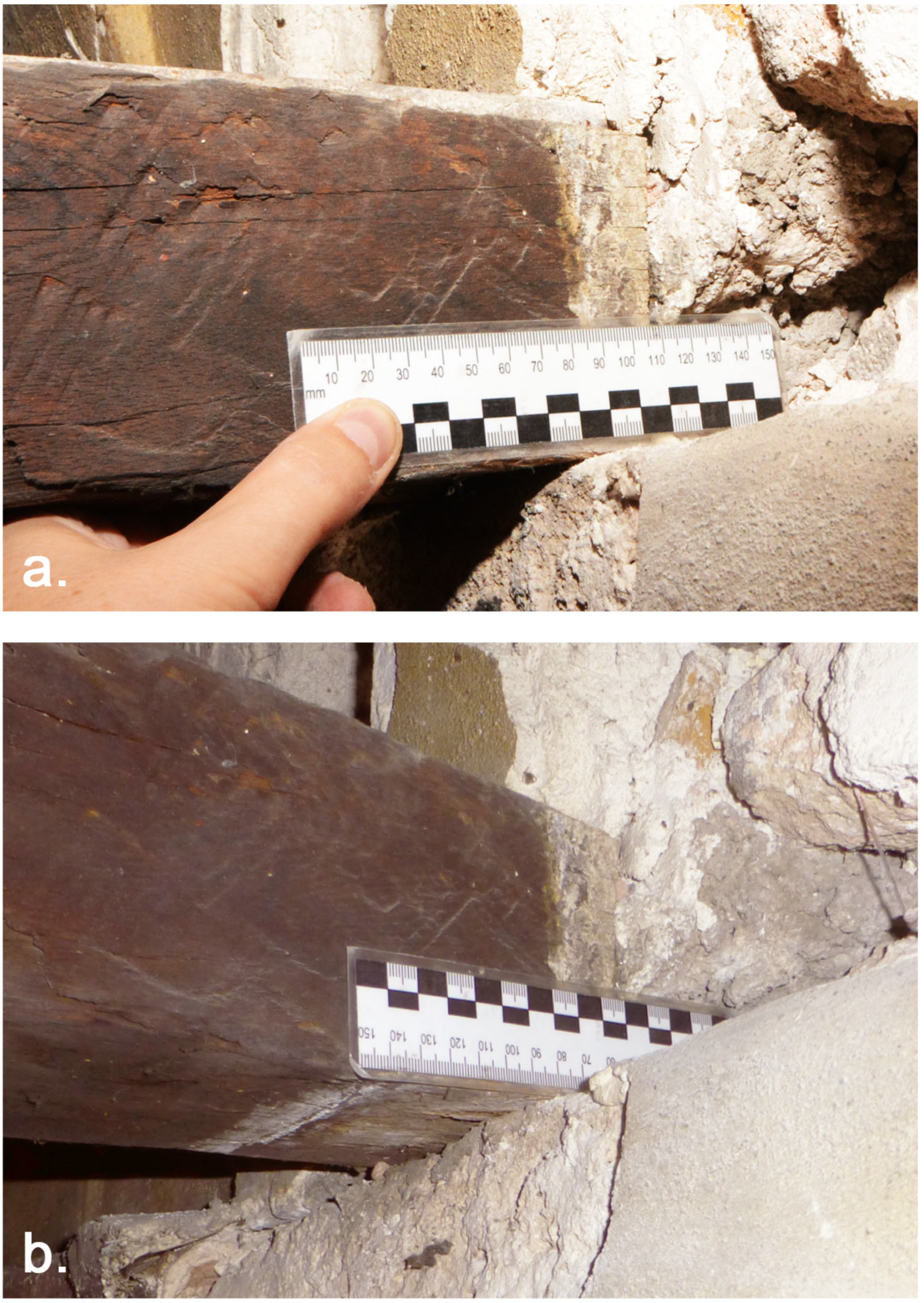
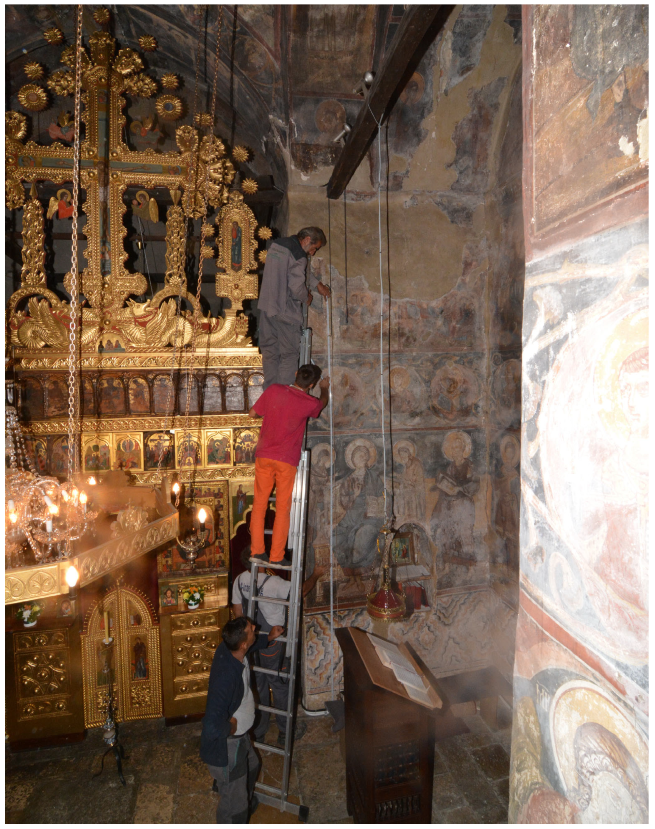
4.1. In Situ Observation and Deformation Measurement as Research Methods

The following was observed on the church: a large number of cracks that are visible on the southern choir as well as on the western wall, cracks on the dome arches (the smallest cracks are on the northern arch), disruption of the connection between the tie-rod and pilasters, and a drawn tie-rod under the southern under-dome arch (Figure 8).
In situ observations, recordings, and measurements of the deformations were performed using a self-levelling line laser. A digital spirit level with a laser beam, a laser distance meter, a plumb line and a building meter were also used during the measurement (Figure 9). A plumb line was used to measure the deviation from the verticality of the walls. A level of 2 m in length and a digital spirit level were placed on the wall in order to measure the deformation—the inclination of the walls—which was measured by the height of the wall, from a height of 0.5 m above the floor to a height of 2.5 m above the floor.
The parapet line and the mid-level cornice were likely constructed horizontally, positioned at the same distance within the church and with height deviations of only a few centimeters (in accordance with the architectural capabilities of the period).
By laser measuring the horizontality, it was established that the unevenness on the church floor is 6.50 cm. The southern part of the floor and the southern part of the mid-level cornice are at a higher elevation compared to the opposite elements of the northern part of the church (Figure 10).
It was also established that the mid-level cornice has a measured inclined height of 28.5 cm, with parts of the altar partition that have a slight deviation from horizontality. A large unevenness appears to the left and right of the altar partition on the walls towards the side choirs (Figure 10).
The verticality of the walls was measured in several places in the church. It was established that the inclination of the northern wall next to the nave in the direction to the north ranges from 12 to 29 mm/m (the upper part of the wall is inclined in relation to the lower part in the north direction) (Figure 11).
The geodetic surveys included surveying the location and cadastral plots, making geodetic drawings of the monastery with the surrounding area, and setting survey markers for geodetic observation subsidence on the church [35].
In order to observe and monitor the subsidence of the building before, during, and after the rehabilitation, survey markers were set in 2021, and an initial survey marked as “0” (zero) was carried out. In the gate of the monastery, two permanent survey markers, R-A and R-B, were placed on stable points on the rock that are not subject to changes in the vertical and horizontal planes. Additionally, 14 survey markers consisting of a permanent component were installed in the characteristic positions on the walls of the church. A temporary component was placed only during the survey and was removed afterward. All observations were made with a digital level instrument, “Sokkia” SDL30, and a levelling bar with a reading code.

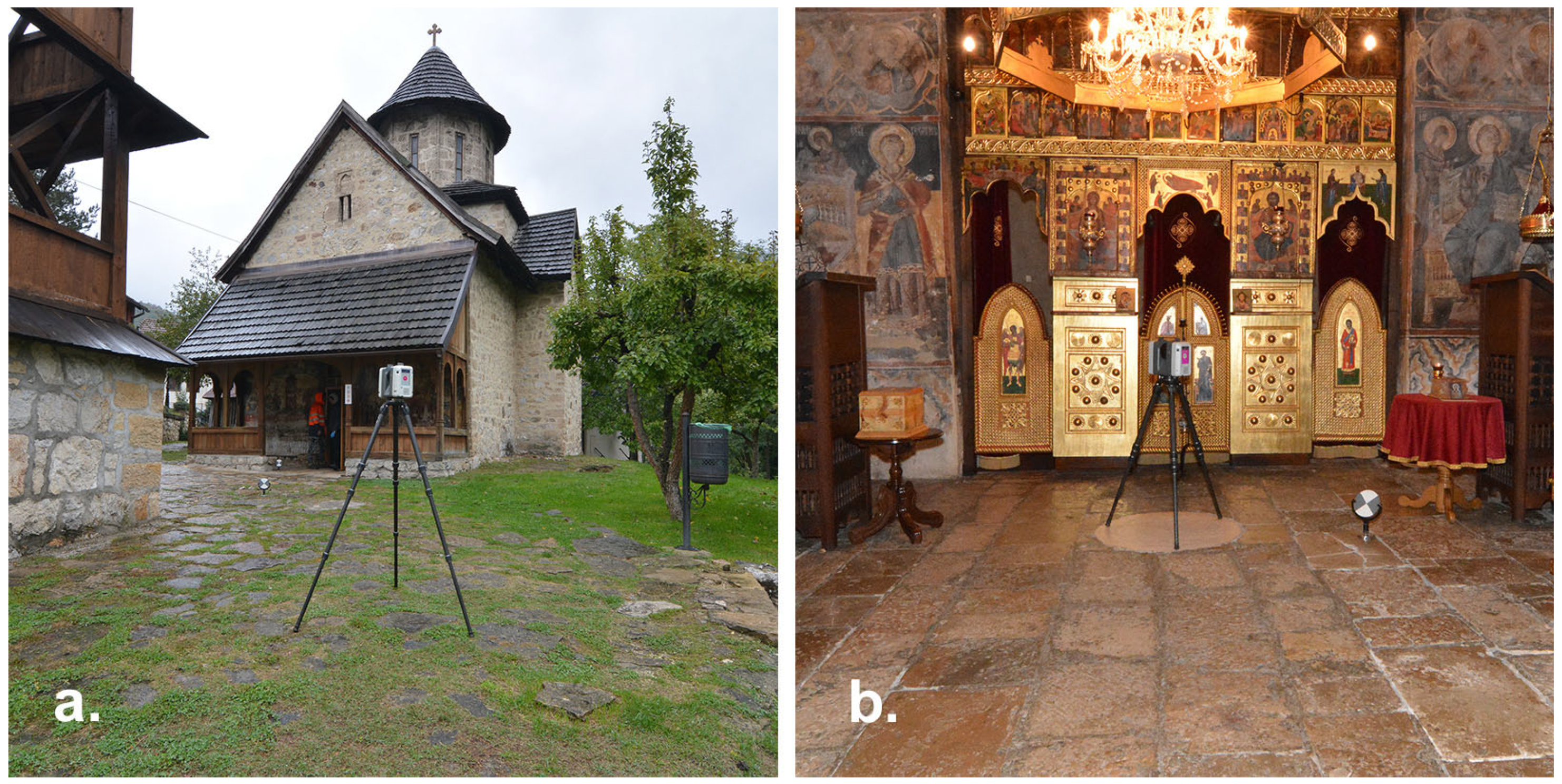
4.2. Three-Dimensional Laser Scanning and Photogrammetry

A non-destructive method of monitoring is represented by 3D laser scanning (Terrestrial Laser Scanning—TLS). Three-dimensional scanning and photogrammetry provide the most precise geometric features and measurements of the inclination of the church as well as the unevenness between the parts of the structure. In situ inspection revealed that the geometry of the church has a high degree of irregularity because it is tilted to the north; for this reason, it was recorded using the TLS method [36].
The equipment used to record the church was a 3D scanner, Leica, model RTC360. In order to cover the entire building and obtain a complete picture, a total of 27 points were placed, from which the building was photographed, of which 11 were outside, 1 was at the church’s entrance, and 15 were inside the church (Figure 12).
The camera placed at the church’s entrance allowed the connection of the exterior and interior shots into a single image. The model was formed as an integral unit that contains a snapshot of the church’s walls from the outside and inside, and it is possible to observe them in the form of silhouettes that show only the points on the bends, enabling a refined observation of the obtained form. Sections of the 3D models were obtained using Leica CloudWorx software 2020.0.1 for AutoCAD. A precise drawing of the existing structure, cladding, terrain, and other details was recorded. The precision of the image allows for the recording of existing damage in the form of cracks, deformations, and inclination in relation to the horizontal plane. Basic dimensions and elevations and relevant horizontal and vertical axes are marked in the drawings. The heights of different reference points inside the object were measured, confirming the presumed deformations of the church’s geometry. Additionally, cracks on the sub-dome arches on the west and south sides are marked and identified on the drawings.
The results of the 3D imaging show that the church has uneven abutments on the northern and western sides. This is most clearly seen by measuring the difference in height at the floor level in the church. The unevenness is also visible at the base of the dome arches in the digital sections of the building created based on the 3D imaging. In the north–south direction at the floor level, a height difference of 18 cm was measured, while at the foot of the arches on these two sides, there is a difference in height of 31 cm. In the east–west direction, the difference in the height of the floor at the extreme points of the church is 23 cm, while the dome arches are at approximately the same height of +5.22 m (Figure 13).

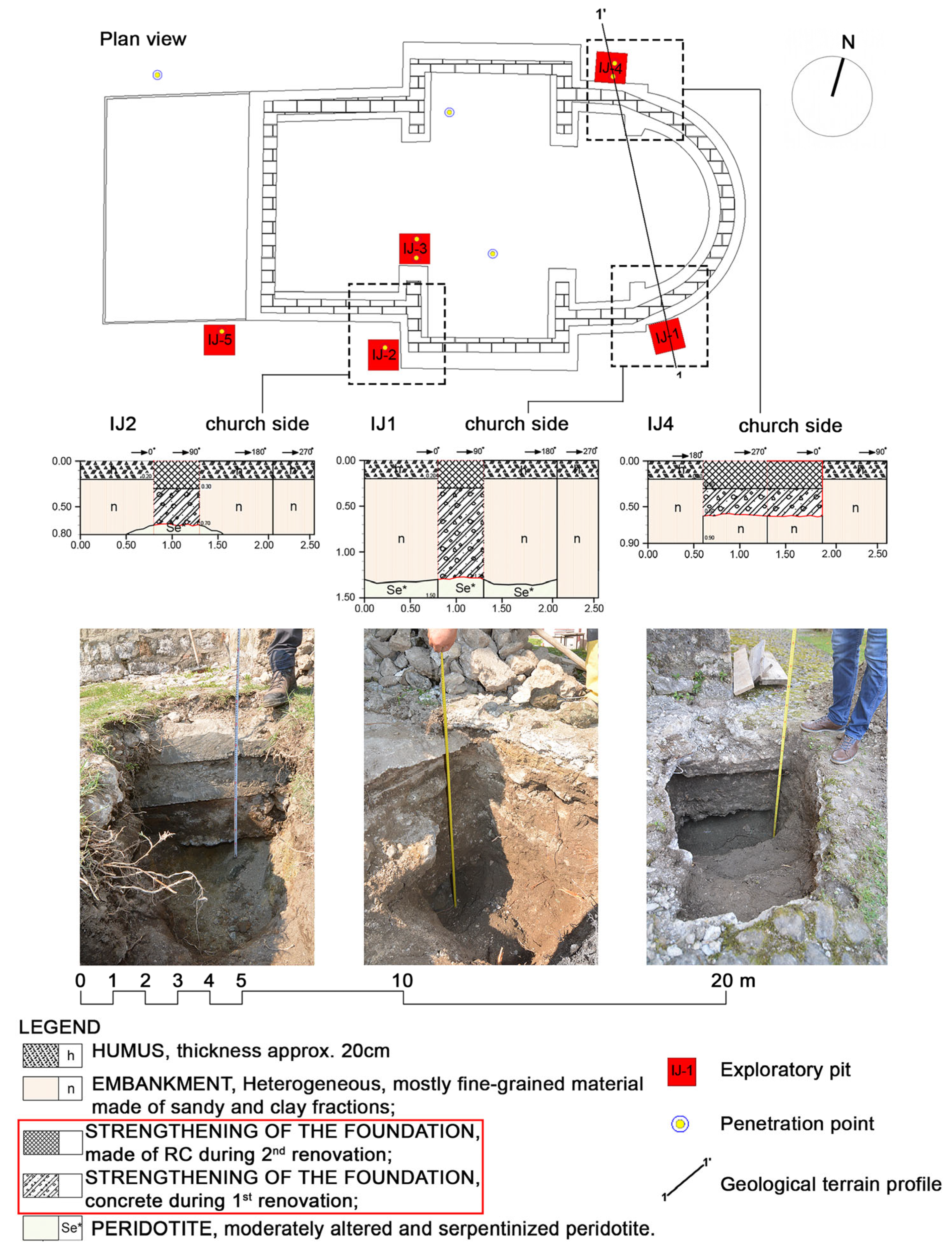
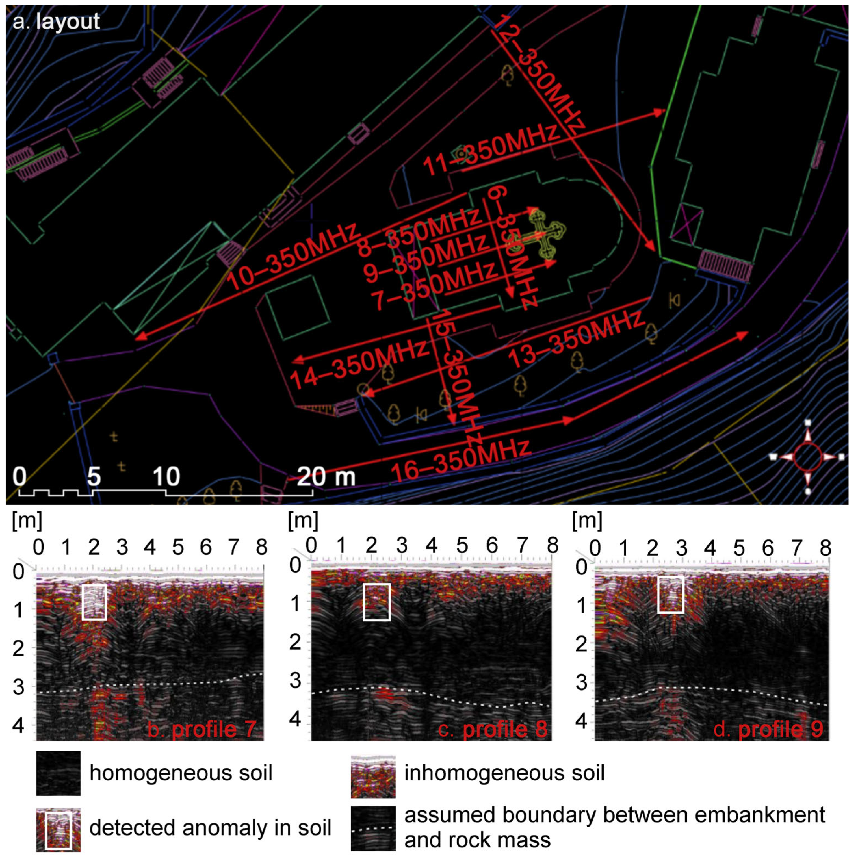
4.3. Geophysical Surveys

Geophysical surveys were carried out using the ground-penetrating radar method (GPR), which enables detailed coverage of the terrain to determine the depth of the supporting solid rock mass. This information is needed to define the steps required for the restoration of the church. The geophysical equipment used in this project is a GPR system SIR4000 with a 350 MHz antenna which gave the best results in depths of soil from 0 to 12 m. The research methodology involves the application of a high-resolution GPR method with a suitable antenna. Investigations were carried out along individual GPR profiles, which were set to adapt to the conditions on the ground and provide answers to the defined problem at the location. The GPR method was applied using an antenna with horizontal resolution from data every 0.01 m GPR profile. The recording time range was 84 ns, and the recording depth was about 4 m because it is a zone with existing foundations and possible interventions for stabilizing foundations using sub-concreting. Research was carried out along six individual profiles of the church gate and four profiles were made in the church itself [37]. The layout of these investigation profiles is given in Figure 14.
The results of the geophysical research are presented in the form of GPR profiles. The horizontal axis on each profile represents the distance travelled, while the vertical axis on the left side of the page represents the estimated depth. A palette of different colors was chosen to display the profile, where homogeneous soil is shown in dark shades (black and dark grey), while light shades correspond to inhomogeneities in the soil (Figure 14). Based on the geophysical research and the interpretation of the obtained data, it can be concluded that the terrain on which the church was built has a heterogeneous composition, and that the material from which the embankment was made has the same composition as the rock mass. Determining the precise boundary between the rock mass and the filled terrain was difficult, assuming it ranges from 2.5 m to 3.5 m, depending on the location. To use these results with greater certainty, it is suggested that research using one of the destructive methods—geological research—be conducted in at least one place.
During the geophysical survey, in the church, under the western trave, a linear anomaly was detected. It runs northwest to southeast and may represent a linear underground object, wall, or a foundation immediately below the ground surface (Figure 14). On the profiles, this object is framed in white.

4.4. Geological Research

Observation of the church’s geometry showed that the church is axially symmetrical in the east–west direction, and the load on the foundations from the north and south sides in relation to the said axis is identical. For this reason, uneven subsidence is not expected on the southern or northern part of the church unless there is a problem with the different bearing capacity of the soil on the southern or northern side. Considering the visible leaning of the church towards the north side and the deviation from the vertical axis, it was assumed that the cause of the problem could be in part of the foundations and the heterogeneity of the soil on which the church is based. The geological survey included the excavation of five exploration pits [38] in zones of identified damage and subsidence of the church to define the depth and dimensions of the foundations, as well as depth at which the rock mass with sufficient bearing capacity is located. The beginning of the geological survey was the formation of three pits on the outside of the church’s southern part, one next to the southwest column on the inside and one with a pit on the east side, next to the north choir, on the outside (Figure 15). They were dug through the embankment up to the level of the foundation reinforcement and represent a destructive research method. During digging, engineering geological mapping of the pits was carried out to take samples, which enabled the determination of the represented lithological detail and their boundaries in the exploration area.
Figure 15. The foundations of the church with the position of the pits and exploration pits IJ-1, IJ-2, and IJ-4 [38].
Buildings 15 02328 g015
The southern part revealed three levels of foundation rehabilitation, due to the largest cracks being in that part of the church (Figure 15-IJ2). The reason for the foundation repair can be found in the fact that the soil has different geotechnical characteristics on the south and north sides of the church (Figure 15). This difference caused the church’s northern wall to subside, resulting in large cracks on the western wall of the church. The subsidence was uneven, which resulted in the appearance of cracks that threatened the stability of the altar apse.
Geological research indicates important characteristics of the terrain on which the church is based [38]. According to geological documentation, it was established that the research area is located on the border of three large geological units: Triassic, Cretaceous, and Jurassic. The embankment on the ground is medium compact and made of heterogeneous material, with sandy, dusty, and clayey components and large pieces of different rocks. In exploration pits IJ-1 and IJ-2, the foundational reinforcement of the church was founded on a solid base made of serpentinites. The foundation of the church’s southern side is also based on a solid foundation. In IJ-1, the serpentinite was altered but of sufficient strength to represent a satisfactory base in terms of bearing capacity and subsidence (Figure 15-IJ1).
In pit IJ-2, the serpentinite was shallower, appearing as a solid, unaltered, and compact rock (Figure 15-IJ2). This rock meets the required qualities in terms of strength, so no additional research on the same samples is needed. On the northern side of the monastery, no solid rock mass was found in the exploration pits up to the level of the foundation reinforcement, which indicates that the reinforcement was found in the ground (Figure 15-IJ4). The foundation on the northern side is built on soil with a much lower compressibility modulus than the soil under the southern foundation. It may also be based on degraded rock mass, which has lower strength and deformation properties. These characteristics are weaker compared to the ground on the southern side of the building.
This finding was confirmed using a practical method, suitable for implementation at the time due to limited financial resources for more extensive exploration. The method involved mechanical soil penetration in pits with rebar, where the soil offered minimal resistance up to three meters below the surface. By penetrating the northern wall inside the church, a solid foundation was confirmed only at 5.6 m from the floor level, while next to the southern wall, it was the case at 3 m.
Minimal investigative work is needed to construct a geotechnical model of the terrain. This includes drilling three exploratory wells and digging one exploration pit. Soil samples will be taken to determine the bearing capacity. The focus is on identifying areas with lower strength and deformation characteristics compared to the ground supporting the church’s foundations on the north side.

5. Discussion

The research, observation, and analysis of how one element affects another have revealed the longstanding impact of subsidence of soil beneath the northern part of the church. This subsidence has caused tilting of the church northward and led to deformations in its structural elements. This paper affirms the earlier assumption that addressing these complexities requires a comprehensive technical and scholarly approach, considering the multitude of factors involved in the overall analysis. All the work carried out during the observation and analysis of problems in a specific locality must be supported systematically, considering broad interdisciplinary cooperation.
The research confirmed the same position on the necessity of forming an interdisciplinary team to prepare a study in such situations as reconstruction, restoration, and protection of monuments to achieve the best result. It is necessary that this team should include engineers, archaeologists, conservators, surveyors, geophysicists, geodesy engineers, and geological engineers in order to offer an adequate and correct perceptions of the impact of the soil’s bearing capacity on the deformations that cause the inclination of church and its devastation.
The church was investigated using different methods to obtain precise information and form an integral picture of the current condition of this monument.
The research methods used to measure vertical and horizontal deformations with wall inclination are non-destructive (ND) methods and include field research:
  • Measuring with self-levelling laser, digital level, laser distance meter, building meter (equipment for architects and builders);
  • Three-dimensional laser scanning, to create digital substrates on which deformations are measured;
  • Geodetic observation and monitoring of subsidence;
The methods of investigating the condition of the ground on which the church is founded are as follows:
  • Geophysical research carried out using the GPR method as a non-destructive method;
  • Geological research and excavation of exploration pits as a destructive method.

5.1. Implications of Historical Review and Previous Restaurations

During previous reconstructions, the experts did not look at the problem appropriately at all. They wrongly believed that the northern side of the church, oriented towards the hill, rested on a solid rock mass and that the southern part, towards the river, rested on ground with a lower load-bearing capacity. This wrong assumption is why there were many repairs to the building on the south side, where most of the cracks were present. The author of one of the previous renovations supports the earlier claim that the southern part of the church was built on soil with inconsistent bearing capacity. This is because the monks’ graves are located directly next to the walls on the southern and eastern sides of the church. These areas had the most favorable conditions for digging, meaning the ground there was the softest. According to the calculations carried out by the mentioned author, the stress in foundation joints was 0.292 MPa under the pilasters that support the dome and after the strengthening it was 0.172 MPa. Also, the stress under the walls of the western aisle (entrance part of the church) and the north and south walls was 0.162 MPa and under the altar apse it was 0.168 MPa [32]. Further research and analysis of existing documentation showed that previous rehabilitation measures were not adequately carried out. The interventions for reconstruction were based on incorrect assumptions, and therefore, the approach was wrong as well.
Based on the literature research, it can be concluded that the church experienced uneven subsidence. This caused cracks that threatened the stability of the altar apse. As a result, the apse collapsed 30 to 40 years after construction. This happened between the completion of the fresco painting in 1633 and the first reconstruction and walling of the apse in 1644 [33,35].
One of the biggest problems in this building is the reinforcement implemented in one of the previous reconstructions by building a concrete ring around the foundation of the entire building. This ring was not built at the building’s foundation level, i.e., above the level of the bottom of the foundation, as evidenced by investigative works in the foundation pits. Many interventions on the foundations from the outside, carried out during previous reconstructions, have just made the execution of new ones even more difficult and complicated.
During the reconstruction in the 1970s, wooden tie-rods reinforced with 60 × 6 mm metal sheets were installed and anchored into the walls. This method was usual for the period of this rehabilitation. These tie-rods have been pulled out of arch abutments today and should not be returned to service, especially not the tie-rod under the southern dome arch. If they were re-anchored into the masonry structure and began to accept impacts, and the building continued to subside, there would be major damage in the upper zones of columns and walls. During the previous restoration, the reinforcements were not carried out as they are today. Contemporary reconstruction would be carried out by drilling holes through the wall and installing anchor plates, which would result in further subsidence of the building, leading to breakage and collapse of the upper part of the building.
One of the biggest problems in this building is the reinforcement implemented in one of the previous reconstructions by building a concrete ring around the foundation of the entire building, which was not built at the building foundation level, i.e., above the level of the bottom of the foundation, as evidenced by investigative works in the foundation pits. Many interventions on the foundations from the outside, carried out during previous reconstructions, have just made the execution of new ones even more difficult and complicated.

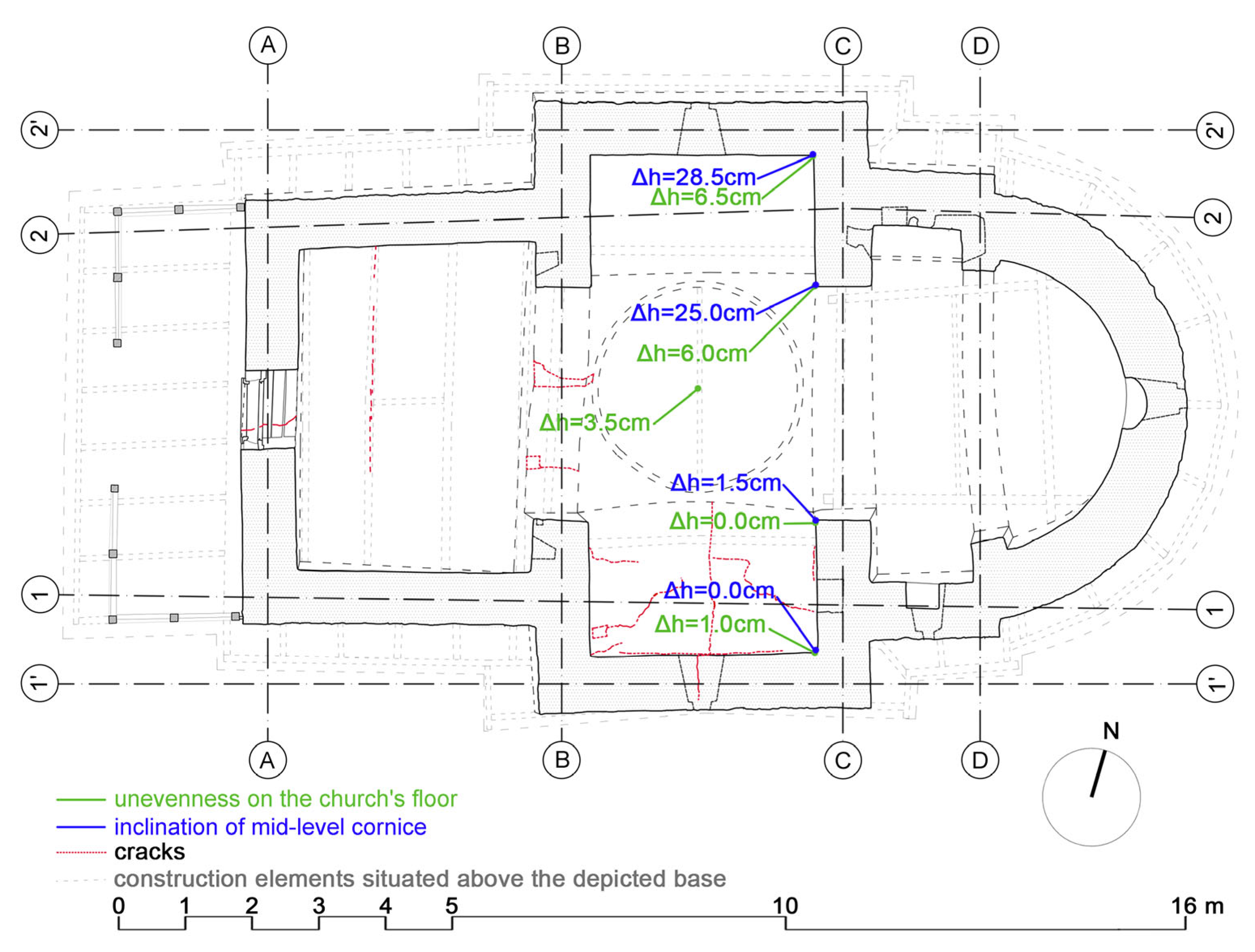
5.2. Implications of In Situ Measurements and 3D Laser Scan and Photogrammetry

The stresses on the building are axially symmetrical, in relation to the east–west axis. On the north side, there is greater subsidence according to all measurements and the 3D scan. The building has tilted to the north side. This suggests there is no problem with stresses in the foundation joint, especially since the biggest cracks on the church are on the south side. The causes of the cracks and subsidence are not the result of different stresses between the north and south sides as these stresses are the same. Instead, the cause is the difference in the ground beneath the church. On the south side, the foundation rests partially on rock mass, while on the north side, it rests on compressible ground. This is the reason for tilting to the north side and subsidence of 28.5 cm. The deformations are on the pilasters on the south side in both directions (Figure 11).

5.3. Implications of Geophysical and Geological Survey Results

Work on restoring the church during the 20th century led to certain problems with the structure. In the previous restorations, the focus was primarily on strengthening the foundations on the southern side. Now, after the geological and GPR surveys have been completed, it can be said that the southern part of the building is found to be better than the other parts and that the subsidence of the church is a consequence of the heterogeneity of the ground in the northern and southern parts.
GPR can be used to determine the level of the solid rock mass, but not its geological composition. In this case, GPR was used to locate the rock mass, which would have been impossible to detect across the entire church site without it. Based on these results, geological investigations were carried out to further analyze the composition of the material and its bearing capacity, ultimately aiding in the identification of the cause of the inclination. Under the floor in the western vestibule, a structure was noticed. It is assumed to be the foundations of an earlier church or foundations that were abandoned during the construction of this church. After that, the western wall with the entrance was built further towards the west in order to obtain a larger, more spacious and longer western route [37].
Through geological research, it is possible to take laboratory soil samples from the exploration pits and obtain precise data on the soil composition to plan future interventions. The results of geotechnical research in several exploration pits confirmed the results of geophysical research—the embankment material is mainly of the same composition as the rock mass. During the excavation of the exploration pits, rehabilitation plans from 1967 were used to prevent reinforcements and avoid damage [32].
As confirmed by geological research, the foundations under the southern part of the church were supported on a solid rock mass. This part of the church did not subside, in contrast to the subsidence and inclination in the opposite northern part, which was not supported by a solid rock mass. Damage and cracks in the construction occurred in those places where the highest tensile stresses are concentrated, namely in the under-dome space. That was why the church building cracked precisely at the place of the highest tensile stresses.
This research confirmed the following assumption: in the case of an inconsistent bearing capacity of the soil under the foundation, this problem can cause different subsidence in parts of the foundations. Such an unfavorable situation can lead to cracks and distortion of the masonry structures.
The latest interdisciplinary research has disproved previous assumptions that the ground under the southern part of the church has a poor bearing capacity (Figure 10). Works in the exploration pits confirmed that the southern part was built on a rock mass. On the northern part, towards the hill, which for decades was believed to be on more stable ground and better founded. However, geological research confirmed the opposite. The church was actually built on terrain with a lower compressibility modulus and there is a rock mass at a greater depth. On the north side of the church, there are smaller cracks or almost no cracks (Figure 10) because the church has subsided evenly.
Three levels of foundation restoration can be observed in the southern part due to the largest cracks being in the southern part of the church. The cracks appeared because the southern part was founded on soil with a higher bearing capacity. In contrast, the northern and most likely the eastern parts were founded on soil with greater compressibility. For this reason, the northernmost wall collapsed, and large cracks appeared on the western and southern walls and other elements of the structure.
Geological research has verified and confirmed that the foundational reinforcement of the church on the south side and the foundations on the same side were built on ground with a sufficient load-bearing capacity. GPR research revealed a change in the environment at a depth of approximately 3.00 m on the northern side. Research using a manual method of mechanical penetration—penetration of a ø16 mm rod under the northern wall—confirmed that the soil offers considerable resistance; that is, the solid rock mass is located at a depth of 5.60 m. This elevation is 2.6 m deeper than the result obtained by checking under the south wall using this handy method.
This leads to the conclusion that the rock mass is located much deeper in the northern part compared to the southern part of the church. This has caused the poor bearing capacity of the soil in the northern area. As a result, the soil in this zone has subsided, causing the church to tilt toward the north.

5.4. Systematical Presentation of Results

Table 2 systematically presents the results of previous tests on the church. Observing the values in Table 2 and comparing the measured values of the inclination of the pilasters, obtained by measurements in 1967 and 2020, it can be concluded that the inclination of the pilasters from the vertical plane is increasing, and the church has continued to tilt and subside in the northern part for four decades.
Through research in the field and an analysis of all the mentioned factors, it was concluded that the foundation on the ground of different bearing capacities caused the inclination of the church. These deformations were a logical consequence in the case of bearing capacity failure in the northern parts of the church.
Further research in this area will require archaeological excavations and the execution of many of sounding pits and several exploratory wells to confirm the conclusions reached about the cause of the deformation and inclination of the church.
It is necessary to determine the depth of the ground where the church’s foundations can be supported to lower the existing foundations to the required depth. Due to the large number of constructions works on strengthening the foundation and rehabilitation that were carried out from the outside in the previous period, it would be the easiest to do the rehabilitation work from the inside by shoring up the foundations and lowering them to the load-bearing ground or by constructing mega piles.
This research has confirmed that various factors such as the weight of the church, soil pressure, and different characteristics of the existing soil as well as the subsequently filled earth during the process of compaction and excavation have had an impact on various changes in the structural elements in the form of greater inclination of the object, i.e., inclination from verticality.
It has been confirmed that before starting the process of carrying out an intervention on the building, certain steps are necessary. First, the occurrence of cracks and inclinations in the building throughout its history must be considered and examined. Second, the characteristics of the soil on which the building is founded must be analyzed. Adding permanent load in the case of an extension or the addition of parts of the building has had an unfavorable impact on the construction. In addition, factors such as war operations, bombing, and ground blasting during the construction of the tunnel represent some of the risks that support the claim about additional causes of damage occurred on this historical building.
The research findings confirm the hypothesis that renovating and applying construction measures in line with conservation requirements can eliminate deformations, stabilize, prevent further inclination, and protect the church’s structural integrity.

6. Conclusions

The church’s poor condition is evident from the noticeable cracks and its tilt northward from the vertical position.
Until the depth and condition of the rock mass under the masonry building are determined, it is not possible to define how the church should be rehabilitated, especially at the level of the foundations on the north side. It is necessary to continue the investigative work through the execution of exploration pits on the northern side. The placement of triaxial dilatometers is a condition that must be fulfilled to monitor cracks and structural elements on the church’s masonry walls. Without this data, it is impossible to start solving the problem of inclination.
This research concludes that the primary cause of inclination is the inconsistent bearing capacity of the foundation soil; thus, deformation will be eliminated by sub-concreting or setting mega piles from the inside of the church and situating the masonry building on a solid rock mass. Furthermore, the survey addresses the deformation but it can also influence future approaches to foundation stabilization in similar heritage structures.
The greatest importance of this work is the discovery of the causes of inclination and deviation in the church and the proposal of a solution to this problem. In this way, the reconstruction will prevent further deformation of the masonry elements and preserve the authentic appearance of this extremely valuable cultural monument. The main contribution of the research approach and findings presented is that this paper can serve as a blueprint or guide. It aims to help future efforts focused on identifying the causes of deformations in cultural heritage structures. It also supports developing strategies for their restoration and the structural rehabilitation of masonry buildings. The significance of this study lies in its potential to impact the professional community involved in similar research and it can be a model or basis for further works and investigations. Emphasizing the importance of the presented methodology and findings serve as a reference for similar cases of the architectural heritage conservation of masonry buildings.
Conservation efforts are often limited by the need to ensure that all materials and interventions align with the original appearance and integrity of the cultural heritage object. All measures and research must be carried out with a firm commitment to maintaining the authentic appearance of the building, as this principle is essential and cannot be compromised in heritage conservation. The greatest contribution of this study, besides the discovery of the cause of inclination of the church, are the recommendations for eliminating the causes of this problem, in compliance with the conservation requirements and the preservation of the authentic visual appearance of the church.
This study highlights the need for a multidisciplinary approach to assess the current condition of the masonry building and identify all relevant factors and agents that could cause damage or further failures, prior to any reconstruction. An incomplete assessment of the object and its environment may paint an unreliable picture, potentially resulting in inadequate interventions that could compromise the masonry structure’s integrity.

Author Contributions

All authors contributed equally to this paper. Conceptualization and methodology: J.I.-Š., N.S., N.M., T.Ž. and N.Š.; validation, investigation: J.I.-Š., N.S., N.M., T.Ž. and N.Š.; resources and data curation: J.I.-Š., N.S., N.M., T.Ž. and N.Š.; writing-original draft preparation: J.I.-Š., N.S., N.M., T.Ž. and N.Š.; writing-review and editing: J.I.-Š., N.S., N.M., T.Ž. and N.Š.; visualization: J.I.-Š., N.S., N.M., T.Ž. and N.Š. All authors have read and agreed to the published version of the manuscript.

Funding

This paper received no external funding.

Institutional Review Board Statement

Not applicable.

Informed Consent Statement

Not applicable.

Data Availability Statement

Data are contained within the article.

Acknowledgments

This research was supported by the University of Belgrade—Faculty of Architecture, LAB—architectural engineering laboratory—structural problems of architectural buildings and LAB—laboratory of architectural space-form, function and materialization.

Conflicts of Interest

The authors declare no conflicts of interest.

References

  1. Šekularac, N.; Debljović Ristić, N.; Mijović, D.; Cvetković, V.; Barišić, S.; Ivanović-Šekularac, J. The Use of Natural Stone as an Authentic Building Material for the Restoration of Historic Buildings in Order to Test Sustainable Refurbishment: Case Study. Sustainability 2019, 11, 4009. [Google Scholar] [CrossRef]
  2. The Nara Document on Authenticity, 199. Available online: http://www.icomos.org/en/charters-and-texts/179-articles-en-francais/ressources/charters-and-standards/386-the-nara-document-on-authenticity-1994 (accessed on 27 May 2019).
  3. Lambrinou, L. Preserving a Monument: The Example of the Parthenon. Conserv. Manag. Archaeol. Sites 2010, 12, 60–74. [Google Scholar] [CrossRef]
  4. Gómez Robles, L. A Methodological Approach Towards Conservation. Conserv. Manag. Archaeol. Sites 2010, 12, 146–169. [Google Scholar] [CrossRef]
  5. Binda, L.; Saisi, A. State of the Art of Research on Historic Structures in Italy. Advanced Research Centre for Cultural Heritage Interdisciplinary Projects. 2001. Available online: https://www.researchgate.net/publication/237440027_State_of_the_Art_of_Research_on_Historic_Structures_in_Italy (accessed on 5 September 2024).
  6. Lourenco, P.B. The ICOMOS Methodology for Conservation of Cultural Heritage Buildings: Concepts, Research and Application to Case Studies. In Proceedings of the Conference REHAB 2014—International Conference on Preservation, Maintenance and Rehabilitation of Historical Buildings and Structures, Tomar, Portugal, 19–21 March 2014; p. 954. [Google Scholar] [CrossRef]
  7. Roca, P.; Cervera, M.; Gariup, G.; Pelà, L. Structural Analysis of Masonry Historical Constructions. Classical and Advanced Approaches. Arch. Comput. Methods Eng. 2010, 17, 99–325. [Google Scholar] [CrossRef]
  8. Hola, J.; Schabowicz, K. State-of-the-art non-destructive methods for diagnostic testing of building structures—Anticipated development trends. Arch. Civ. Mech. Eng. 2010, 10, 5–18. [Google Scholar] [CrossRef]
  9. D’Ayala, D.F.; Forsyth, M. What is conservation engineering? In Structures & Construction in Historic Building Conservation; Forsyth, M., Ed.; Blackwell Publishing Ltd.: Hoboken, NJ, USA, 2007; pp. 1–11. [Google Scholar] [CrossRef]
  10. Egels, Y.; Kasser, M. Digital Photogrammetry; Taylor & Francis: London, UK; New York, NY, USA, 2002; 376p. [Google Scholar] [CrossRef]
  11. Richter, T.; Fouad, N.A. Guidelines for Thermography in Architecture and Civil Engineering: Theory, Application Areas, Practical Implementation; Birkhäuser: Basel, Switzerland, 2021; 176p, ISBN 978 3 0356 2267 6. [Google Scholar] [CrossRef]
  12. Jol, H.M. (Ed.) Ground Penetrating Radar: Theory and Applications; Elsevier Science: Amsterdam, The Netherlands, 2009; Volume 18, 524p, ISBN 978 0 444 53348 7. [Google Scholar] [CrossRef]
  13. Diz-Mellado, E.; Mascort-Albea, E.J.; Romero-Hernández, R.; Galán-Marín, C.; Rivera-Gómez, C.; Ruiz-Jaramillo, J.; Jaramillo-Morilla, A. Non-destructive testing and Finite Element Method integrated procedure for heritage diagnosis: The Seville Cathedral case study. J. Build. Eng. 2021, 37, 102134. [Google Scholar] [CrossRef]
  14. Raszczuk, K.; Karolak, A. Correlation between the cracking pattern of historical structure and soil properties: The case of the church in Kożuchów. Herit. Sci. 2021, 9, 43. [Google Scholar] [CrossRef]
  15. Casarin, F.; Valluzzi, M.R.; da Porto, F.; Modena, C. Evaluation of the structural behaviour of historic masonry buildings by a sonic pulse velocity method. In Structural Studies, Repairs and Maintenance of Heritage Architecture X; Brebbia, C.A., Ed.; WIT Press: Southampton, UK, 2014; pp. 227–236. [Google Scholar] [CrossRef]
  16. Watt, D. Building Pathology: Principles and Practice, 2nd ed.; Blackwell Publishing: Oxford, UK, 2007. [Google Scholar]
  17. Huma, I. Investigating, monitoring and load testing historic structures. In Structures & Construction in Historic Building Conservation; Forsyth, M., Ed.; Blackwell Publishing: Oxford, UK, 2007; pp. 64–81. [Google Scholar] [CrossRef]
  18. Saisi, A.; Gentile, C. Investigation Strategy for Structural Assessment of Historic Towers. Infrastructures 2020, 5, 106. [Google Scholar] [CrossRef]
  19. Penelis George, G.; Penelis Gregory, G. Structural Restoration of Masonry Monuments; CRC Press: Boca Raton, FL, USA; Taylor & Francis Group: Abingdon, UK, 2020; ISBN 978-0367109479. [Google Scholar] [CrossRef]
  20. Feilden, B.M. Conservation of Historic Buildings; Architectural Press: Oxford, MA, USA, 2003; p. 64. ISBN 978-0750658638. [Google Scholar] [CrossRef]
  21. Lignola, G.P.; Buratti, N.; Cattari, S.; Parisi, F.; Ubertini, F.; Alfano, S.; Ierimonti, L.; Meoni, A.; Sivori, D.; Virgulto, G. Validated and Optimized Strategies for Preserving Historical Heritage Towards Natural and Anthropic Risks: Insights from the DETECT-AGING Project. Buildings 2025, 15, 693. [Google Scholar] [CrossRef]
  22. Egglezos, D.; Ioannidou, M.; Moullou, D.; Kalogeras, I. Geotechnical issues of the Athenian Acropolis. In Geotechnics and Heritage; Bilotta, E., Flora, A., Lirer, S., Viggiani, C., Eds.; CRC Press: London, UK; Taylor & Francis Group: Boca Raton, FL, USA, 2013; p. 22. [Google Scholar] [CrossRef]
  23. Šekularac, N.; Čikić Tovarović, J.; Ivanović-Šekularac, J. Cultural heritage and structural stability of the old rampart wall, Holy Mount Athos–Case study. Struct. Eng. Int. 2017, 3, 353–361. [Google Scholar] [CrossRef]
  24. Przewłócki, J.; Dardzinska, I.; Swinianski, J. Review of historical buildings’ foundations. Géotechnique 2005, 55, 363–372. [Google Scholar] [CrossRef]
  25. Ukleja, J. Renovation of the historic building after damage connected with foundations subsidence—Case study MATEC Web of Conferences. In Proceedings of the 3rd Scientific Conference Environmental Challenges in Civil Engineering, Opole, Poland, 23–25 April 2018; p. 9. [Google Scholar] [CrossRef]
  26. Egglezos, D.; Moullou, D.; Ioannidou, M. The role of the geotechnical engineer in archaeological work: The Greek experience. In Proceedings of the Second International Symposium on Geotechnical Engineering for the Preservation of Monuments and Historic Sites, Napoli, Italy, 30–31 May 2013; Taylor & Francis Group: London, UK, 2013; pp. 359–366. [Google Scholar] [CrossRef]
  27. Shen, L.; Yang, B.; Yang, Y.; Yang, X.; Zhu, W.; Wang, Q. Real-Time Monitoring for Monolithic Movement of a Heritage Curtilage Using Wireless Sensor Networks. Buildings 2022, 12, 1785. [Google Scholar] [CrossRef]
  28. Čanak Medić, M. Blagoveštenje pod Kablarom. Saopštenje XIX; Beograd, Republički zavod za zaštitu Spomenika Kulture: Belgrade, Serbia, 1970; pp. 199–221. [Google Scholar]
  29. Rajić, D.; Timotijević, M. Manastiri Ovčarsko-Kablarske Klisure, 2nd ed.; Narodni muzej: Čačak, Serbia, 2012; ISBN 978 86 84067 44 1. Available online: https://openlibrary.org/books/OL30953510M (accessed on 10 September 2024).
  30. Bošković, Đ.; Zdravković, I.; Garašanin i Jovan Kovačević, M. Spomenici Kulture u Ovčarsko-Kablarskoj Klisuri; Ovčarsko-kablarski manastiri: Čačak, Serbia, 1991; p. 72. [Google Scholar]
  31. Stefanović Karadžić, V. Početak Opisanija Srpski Manastira; Ovčarsko-kablarski manastiri; Gradac: Čačak, Serbia, 1991; Istoriski glasnik: Organ Istoriskog društva Narodne Republike Srbije (1–2, 1990–1992, str. 145–146) januar–april: 19 (98/99); p. 15. ISSN 0021-2644. [Google Scholar]
  32. Hrabovski, O. Konstruktivna Asanacija Stabilizacija Crkve Manastira Blagoveštenja pod Kablarom, Saopštenje IX. Beograd, Republički Zavod za Zaštitu Spomenika Kulture, 1970. pp. 189–198. Available online: https://www.heritage.gov.rs/cirilica/Download/Saopstenja/Saopstenje-IX-1970/Saopstenje_IX_1970_Konstruktivna_asanacija_i_stabilizacija_crkve_manastira_Blagovestenja_pod_Kablarom.pdf (accessed on 20 September 2024).
  33. Čanak Medić, M.; Hrabovski, O. Projekat Asanacije Restauracije i Konzervacije Crkve Manastira Blagoveštenja—Kablarskog; Zavod za zaštitu spomenika kulture Kraljevo: Kraljevo, Serbia, 1967. [Google Scholar]
  34. Ahmadi, S.S.; Karanikoloudis, G.; Mendes, N.; Illambas, R.; Lourenço, P.B. Appraising the Seismic Response of a Retrofitted Adobe Historic Structure, the Role of Modal Updating and Advanced Computations. Buildings 2022, 12, 1795. [Google Scholar] [CrossRef]
  35. Geodetic Bureau. GEOMETAR 036“. Elaboration of Geodetic Works for the Control of Foundation Subsidence in the Annunciation Monastery on the Plot 2318 K.O; Geodetic Bureau: Kraljevo, Serbia, 2021. (In Serbian) [Google Scholar]
  36. Vekom Geo d.o.o. Report on 3D Laser Imaging of the Object; Vekom Geo, d.o.o.: Belgrade, Serbia, 2021. (In Serbian) [Google Scholar]
  37. Centre for New Technologies. Report on 3D Laser Imaging Report on Geophysical Research at the Location of the Annunciation Monastery; Ovčar Banja: Belgrade, Serbia, 2020. [Google Scholar]
  38. Geo-In International d.o.o. Report on Engineering Geological Research for the Needs of the Rehabilitation of the Annunciation Monastery; Geo-In International d.o.o.: Belgrade, Serbia, 2021. [Google Scholar]
Figure 1. The exterior of the church.
Buildings 15 02328 g001
Figure 2. The interior of the church: a fresco painting from the 17th century.
Buildings 15 02328 g002
Figure 4. Drawings of the designed and implemented strengthening measures in the foundations of the southern side of the church, with new reinforced concrete (RC) foundation elements—from the Repair and Reconstruction Project (1966). During the intervention, temporary wooden supporting elements were in use, as shown [32].
Buildings 15 02328 g004
Figure 5. Detail of the Ø60 mm steel tie-rod removed from the southeast pillar, precisely measured with a ruler for forensic archaeological photography.
Buildings 15 02328 g005
Figure 6. Detail of hanging steel tie-rod in the area of the pilasters in 1970 [32].
Buildings 15 02328 g006
Figure 7. Cracks on the church.
Buildings 15 02328 g007
Figure 8. The tie-rod pulled out of the bearing: precise measurements using a ruler for forensic archaeological photography; (a) top view; (b) bottom view.
Buildings 15 02328 g008
Figure 9. Manual measurement of the deformations in the southeast pilaster.
Buildings 15 02328 g009
Figure 10. Measured deviation from horizontal in the floor and in mid-level cornice in the nave, with presentation of existing cracks.
Buildings 15 02328 g010
Figure 11. Comparison of the inclination of the church in 1967 [32] and 2020.
Buildings 15 02328 g011
Figure 12. Arrangement of camera positions during 3D recordings; (a) exterior; (b) interior.
Buildings 15 02328 g012
Figure 13. Digitized section through the church with cracks position and 3D point cloud display: (a) cross section; (b) longitudinal section; (c) west elevation of the church.
Buildings 15 02328 g013
Figure 14. The GPR investigation profiles. (a). The positions of the profiles on the site. (b) Profile 7 of the site. (c) Profile 8 of the site. (d) Profile 9 of the site, with marked linear structure and the boundary of the embankment and rock mass [37].
Buildings 15 02328 g014
Table 1. Chronology of restoration works.
DateDevastated/Cause/HazardIntervention
1601 Church built.
1644 Restored church and rebuilt altar apse [27].
Church burnt down.
1865 Restored church.
1906 Restored church.
1908
1913
Monastery abandoned.
1932 Restored church and reuse
- Works on the structural stability:
Strengthening the foundation in the form of a ring around the object (w/h = 25/40 cm).Application of Ø60 mm steel tie-rods under the mid-level cornice along the length of the building.
1946 Construction of hydropower plant “Ovčar Banja”, construction of tunnels, and blasting.
Consequence: cracks on the altar apse, and its separation from the walls.
1947 Tunnelling under the monastery complex.
Consequence: cracks on the facade, spreading of arches along the ports, supports of the dome.
1966 Works to ensure the stability of the church:
RC ring reinforcements in the southeast zone (around the south choir, altar apse to the north choir) w/h = 50/60 cm. Designed and executed RC ring beam on the walls.
Replacement of steel tie-rods with buried wooden tie-rods at mid-level cornice. Installation of 4 wooden tie-rods reinforced with steel sheets on the west side of the church and at the sub-dome arches of the church.
Table 2. Overview of the results obtained through the in situ inspection within the church of the Monastery of Annunciation in 2020/2022.
Research FindingsMain ResultsReferences
Measurements in situ
  • Detailed verification of building dimensions
  • Damage location:
   Floor—SE pilaster h0 = 0.0 cm, north wall hs = −6.5 cm
   Mid-level cornice—south wall h0 = 0.0 cm, north wall hvs = −28.5 cm
   Wall inclination—
     NE part of the north wall: 20 mm/m to the north
     NE pilaster: 35 mm/m to the north
     Apse threads: 31 mm/m to the east
     SW corner of the west wall: 28 mm/m to the west
   Inclination of pilasters—
     SE—horizontal movements of the mid-level cornice 9.5 cm (1967)/15.5 cm (2020)
     SW—horizontal movements of the mid-level cornice 17.5 cm (1967)/23.5 cm (2020)
  • Rebar penetrations in the nave: N—resistance at a depth of 5.6 m
     S—resistance at a depth of 3.0 mJ resistance at a depth of 3.0 m
Data from 1967 [32]

Data from 2020/2022 in situ
NDT TestMain ResultsReferences
Laser levelling
  • Set zero series for future monitoring of the subsidence of the building during and after rehabilitation through 14 reference points on the foundations of the building.
[35]
3D laser scan and photogrammetry
  • Inconsistencies: floor—South–north—18 cm
            East–west—23 cm
            Mid-level cornice—south–north—31 cm
[36]
Ground-Penetrating
Radar (GPR)
  • Verification of the filling structure and layer thickness:
     Soil and rock mass of the same composition
     The depth of the rock mass is in the range of 2.5–3.5m
  • Detection of the remains of underground linear objects in profiles 7–9.
[37]
DT TestMain ResultsReferences
Soil properties
  • Layer thickness and mechanical properties
  • Observing the position of the foundation and the depth of the foundation through 5 exploration pits
  • IJ1: Visible 2 reinforcements on the outside of the foundation—one of them is above the elevation of the foundation.
  • IJ2: Visible 3 reinforcements on the outside of the foundation—the lowest one is above the elevation of the foundation.
  • IJ3: The foundation of the SW pillar can be seen in the form of a stone buttress bound with lime mortar.
  • IJ4: Visible 2 reinforcements on the outside of the foundation—one of them is above the elevation of the foundation.
  • IJ5: Visible 2 reinforcements made in different periods.
[38]
Disclaimer/Publisher’s Note: The statements, opinions and data contained in all publications are solely those of the individual author(s) and contributor(s) and not of MDPI and/or the editor(s). MDPI and/or the editor(s) disclaim responsibility for any injury to people or property resulting from any ideas, methods, instructions or products referred to in the content.

