A State-of-the-Art Review on the Influence of Porosity on the Compressive Strength of Porous Concrete for Infrastructure Applications


 ,
, 
Abstract
1. Introduction
2. Properties of Porous Concrete
2.1. Workability
2.2. Density
2.3. Compressive Strength of Porous Concrete
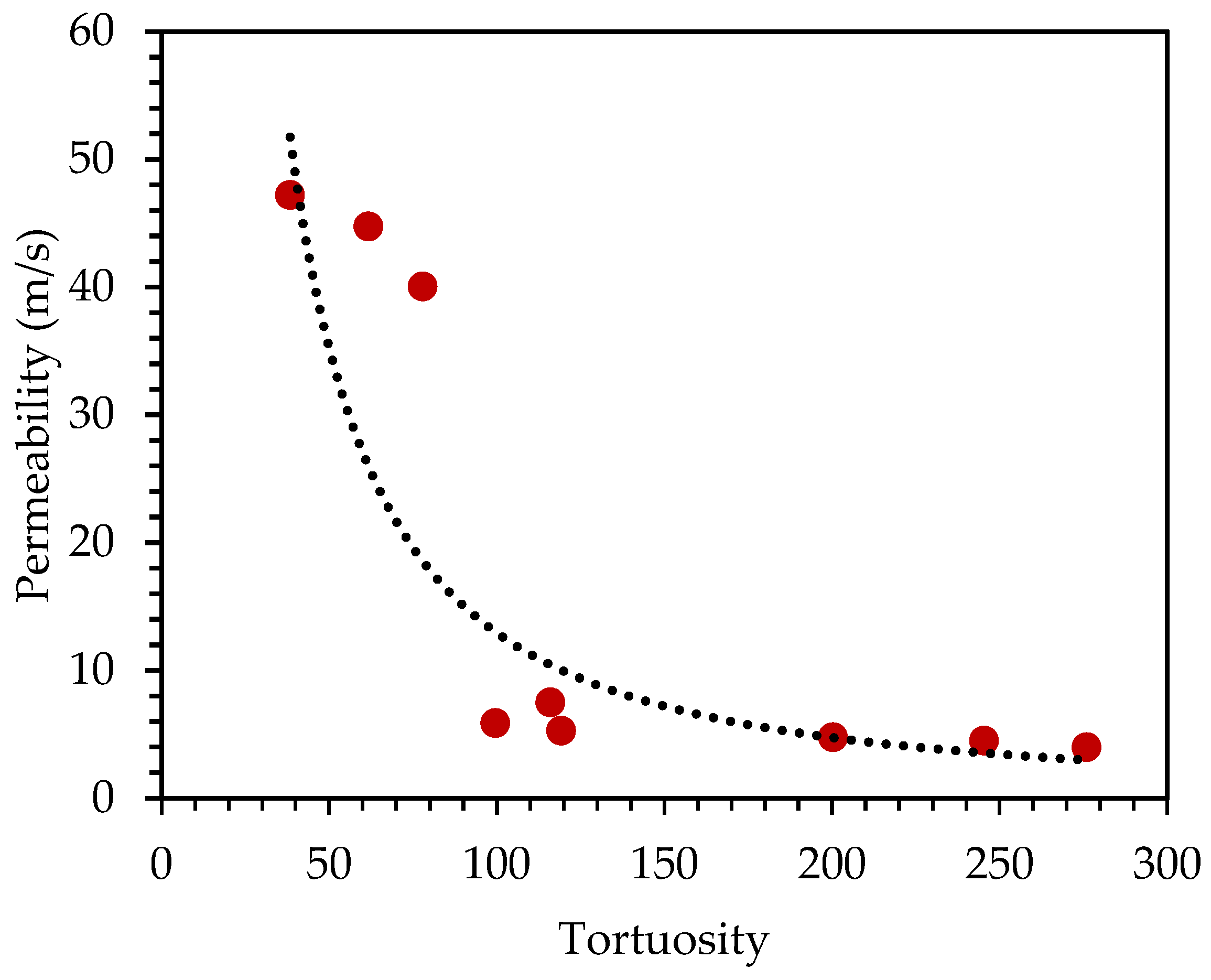
2.4. Permeability
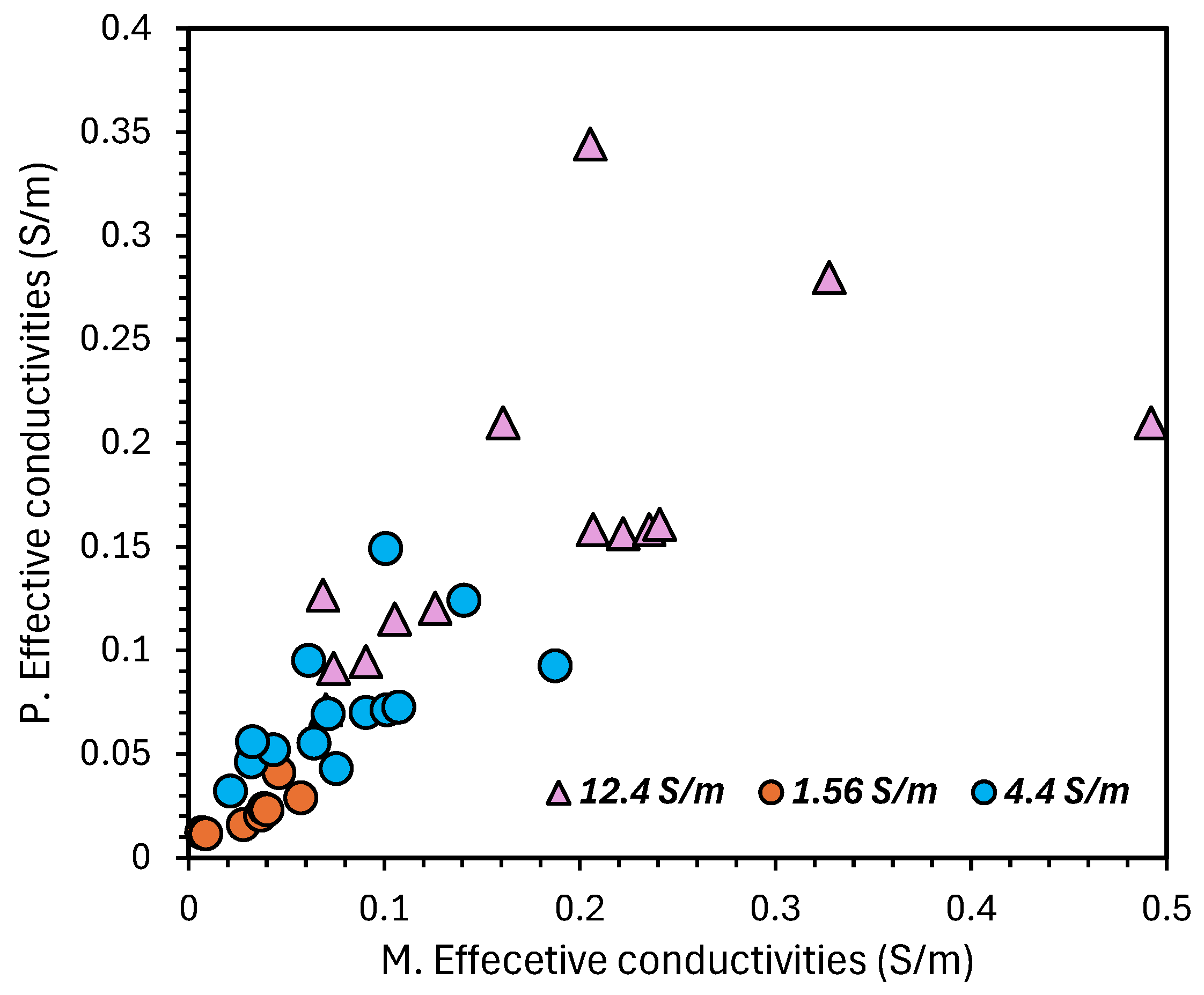
2.5. Conductivity
2.6. Elastic Modulus
2.7. Porosity
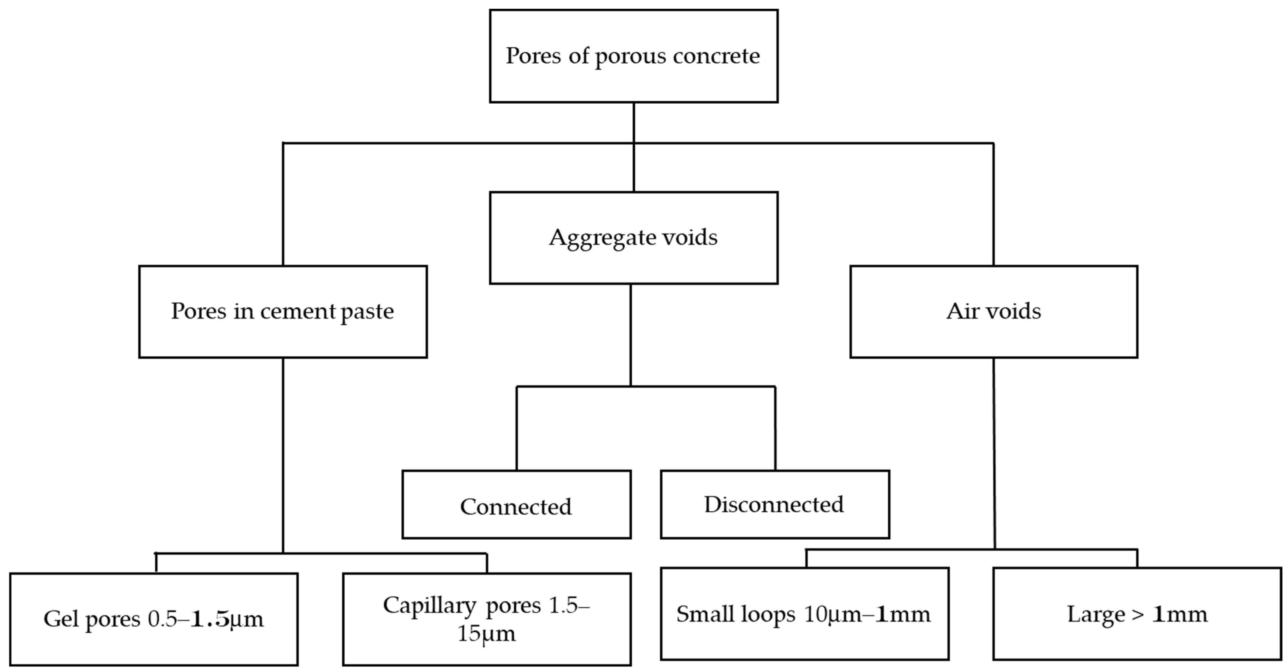
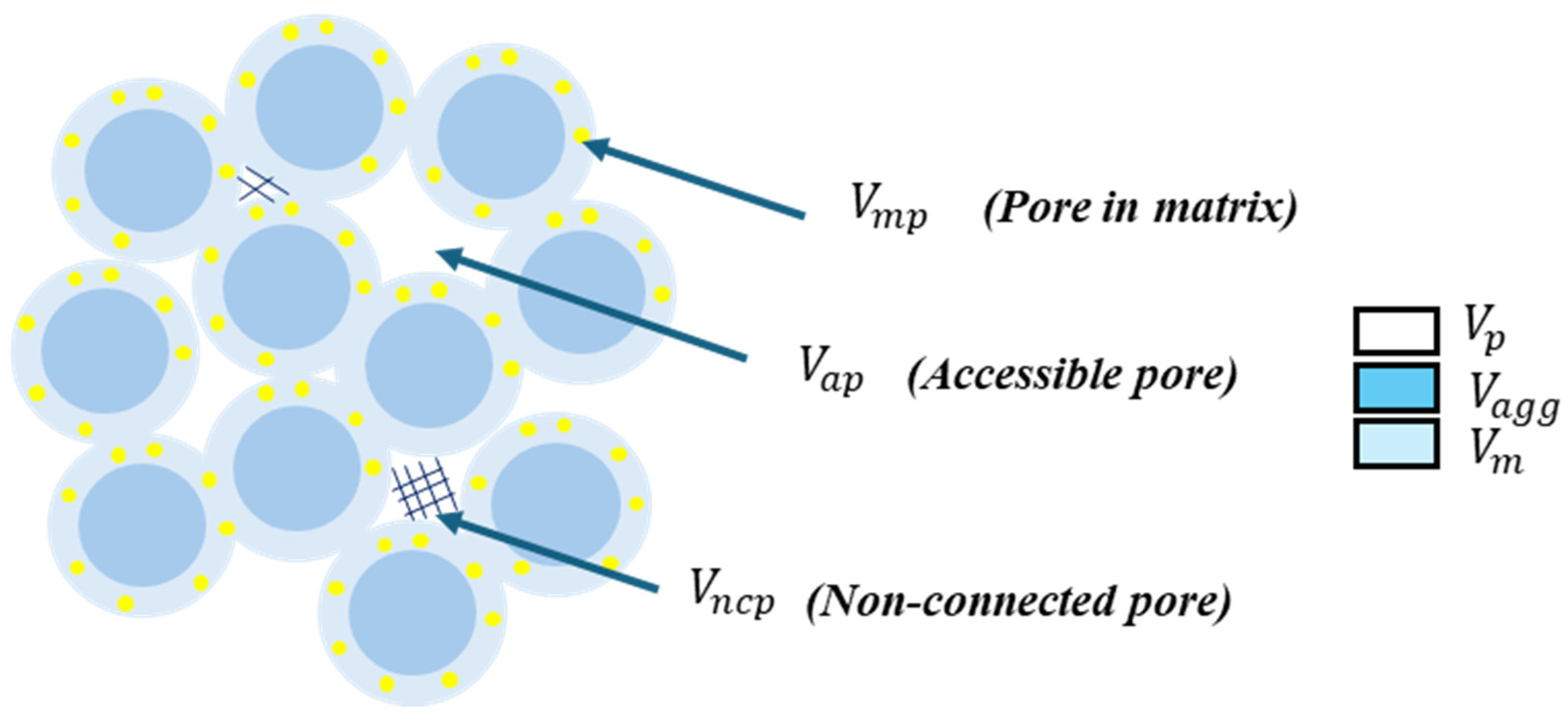
2.7.1. Pore Structure
2.7.2. Effective Porosity
- Øe is the effective porosity.
- M1 is the mass of the oven-dried sample.
- M2 is the mass of the container filled with water.
- M3 is the container with saturated sample filled with water at the same level.
- ρw is the density of water.
- VT is the volume of the sample.
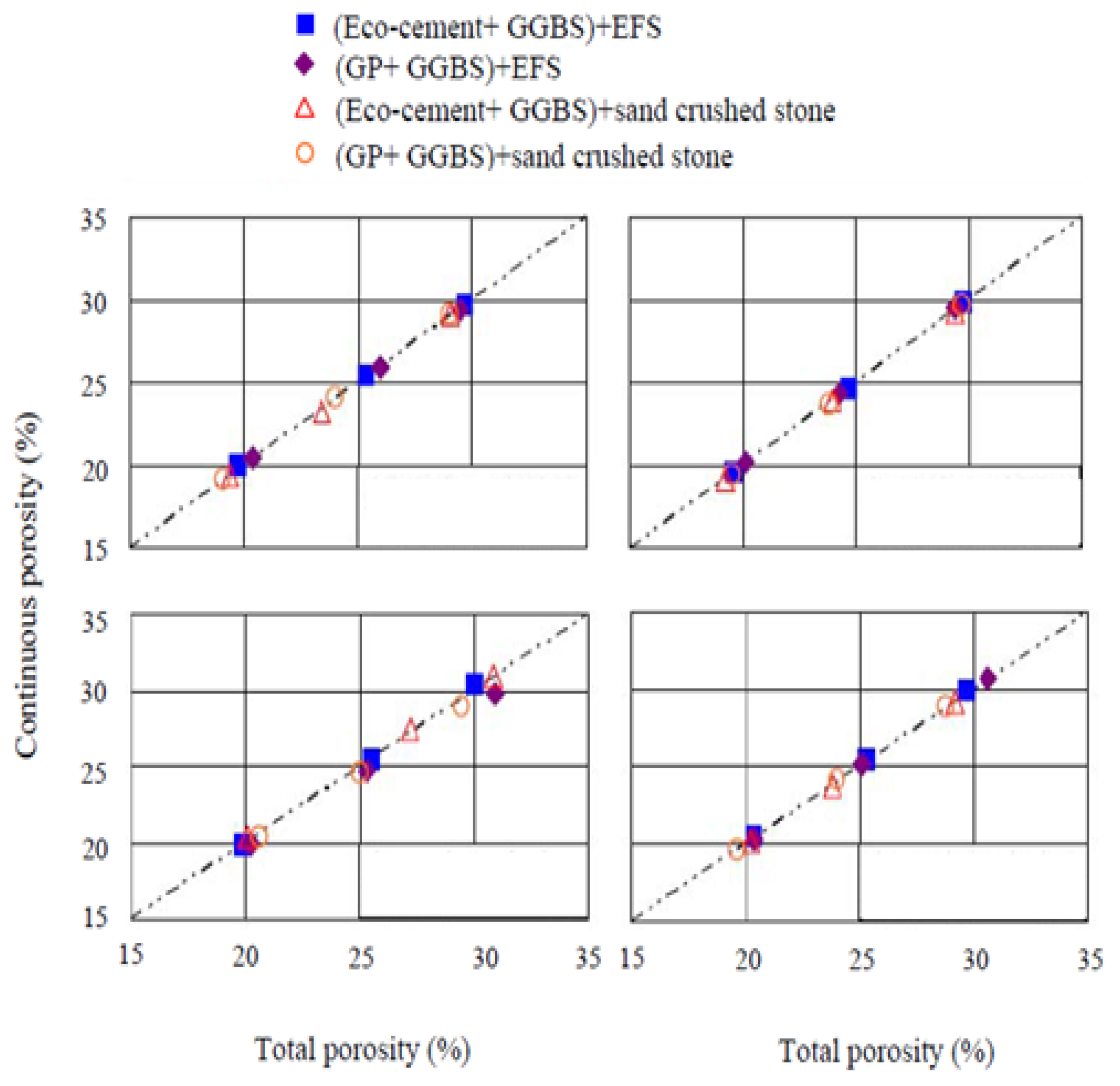
2.7.3. Effective Porosity Versus Total Porosity
3. Factors Affecting the Porous Concrete
3.1. Cement Binder
3.2. Aggregates
3.3. Admixtures
3.4. Mix Design
3.5. W/C Proportion
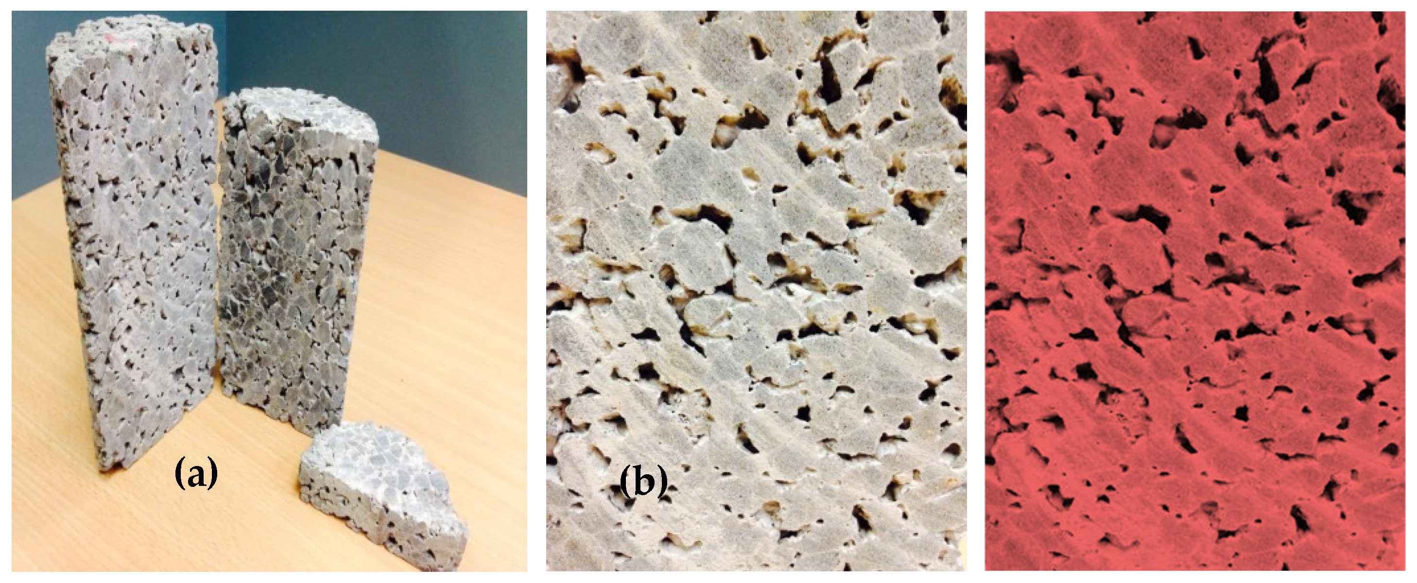
4. Measurement of Porosity
4.1. InstroTek-Based Corelok Sealing Technique
4.2. Weight Differentiation Method
4.3. Japan Concrete Institute (JCI) Method
4.4. Theoretical Method
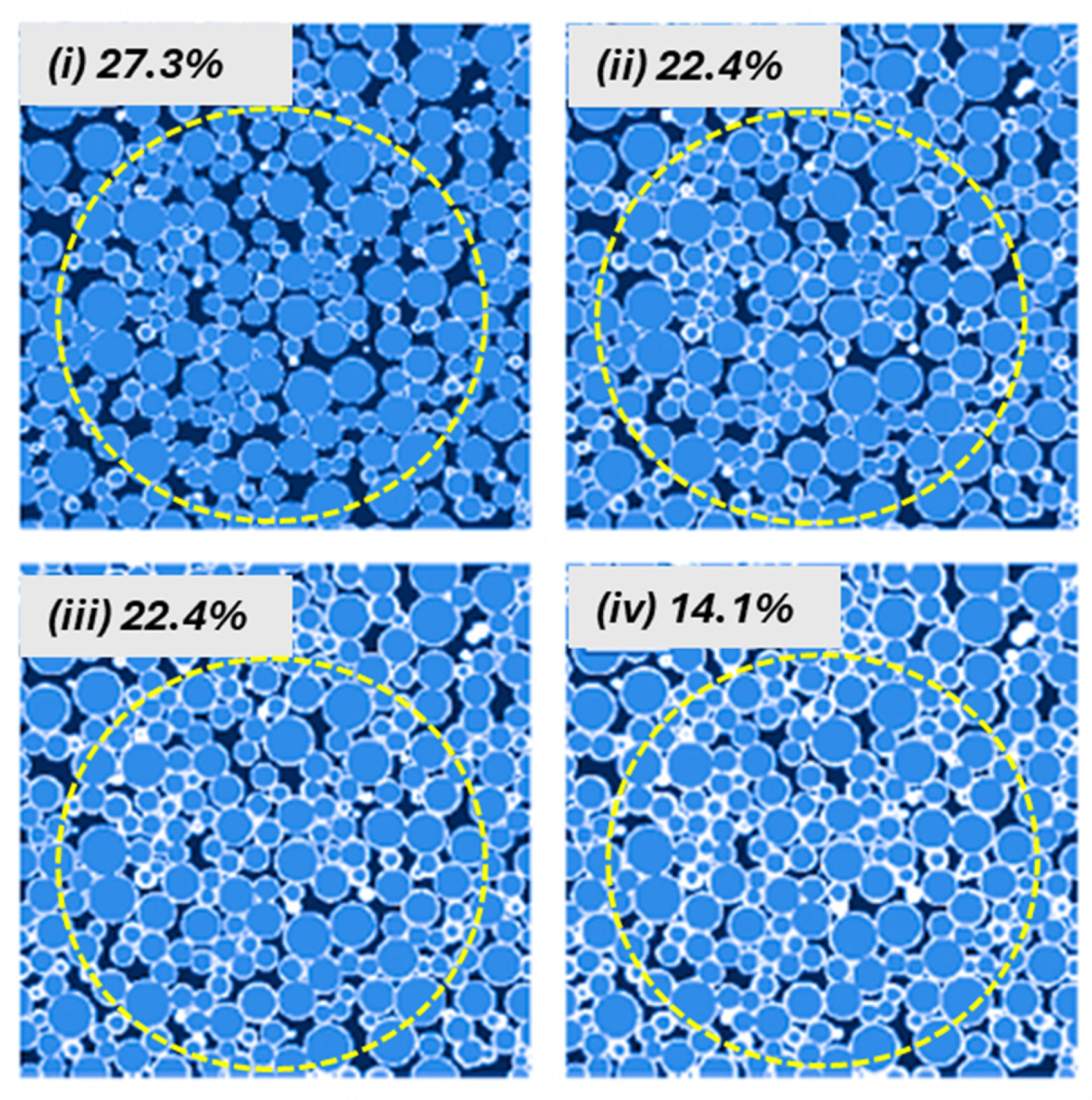
4.5. Image Analysis Method
4.6. Image Analysis vs. Mathematical Model
5. Discussion
5.1. Comparison of Properties of Porous Concrete and Conventional Concrete

| Properties | Porous Concrete | Conventional Concrete | References |
|---|---|---|---|
| Workability | 80 mm | 70 mm | [162] |
| Compaction factor | 0.82 | 0.85 | |
| Density | 1500 to 2200 Kg/m3 | 2400 Kg/m3 | [162,163,164] |
| Compressive strength 28 days | 2.5–34.5 MPa | 46.5 MPa | [119,172,173,174] |
| Permeability | 0.34 cm/s, or 200 L/m2/min) | 2.39 × 10⁻¹¹ m/s | [79,162,173,175] |
| Elastic modulus | 8–15 GPa (25–18% porosity). | 30 GPa | [117,140,172] |
| Porosity | 15% to 30% | 1–3% | [63,85,176] |
5.2. Influence of the Factors on the Properties
5.3. Effect of Porosity Measurement Methods
5.4. Optimal Pore Characteristics in Porous Concrete
5.5. Development of Standard Specifications
5.6. Proposed Guidelines for Overcoming the Challenges of Porous Concrete
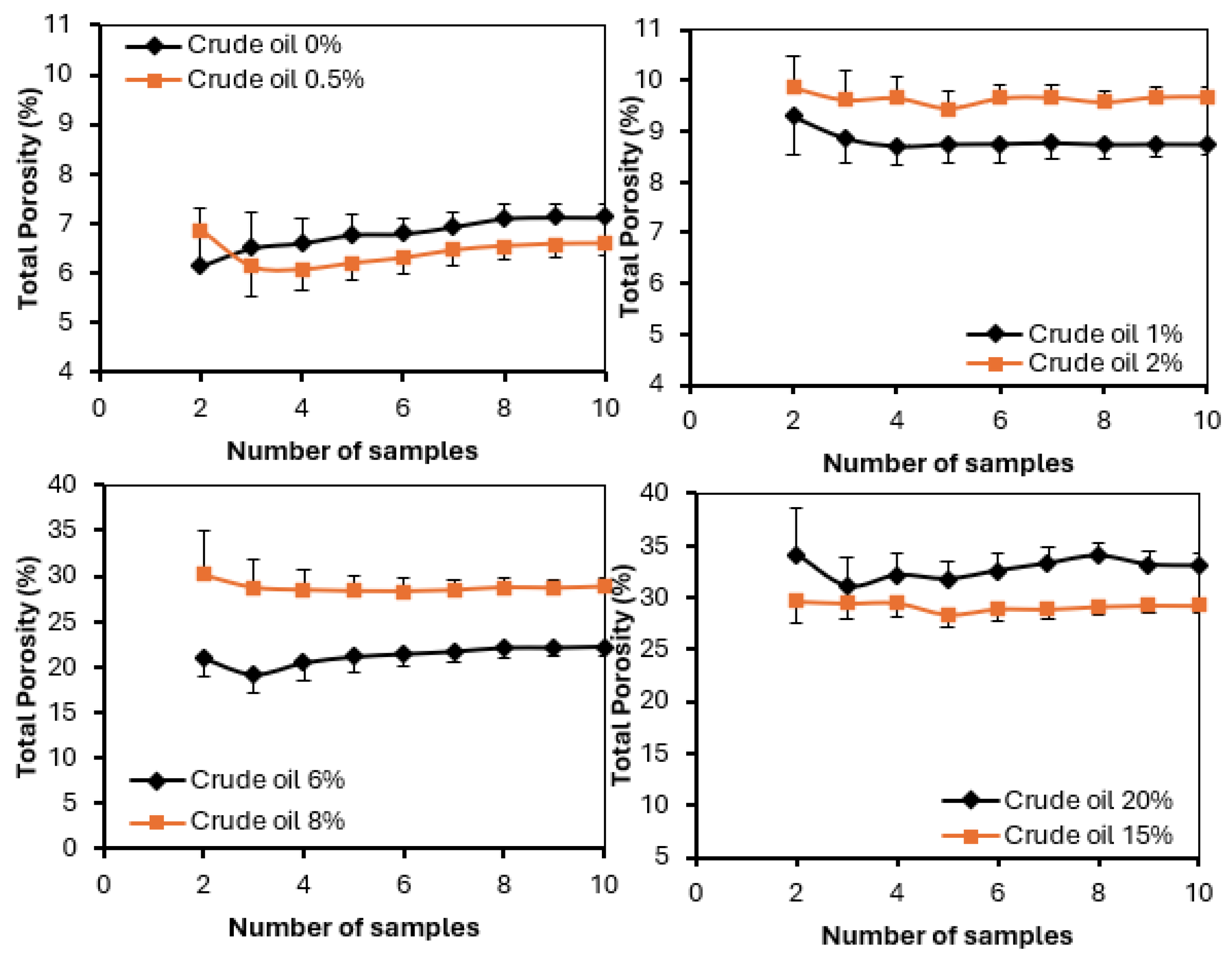
- By employing fibre-reinforced porous concrete, it has been shown that the porous concrete displayed much better rates of permeability than the control mix. This was demonstrated by the fact that the Ultra-Fibre was used. There was a 234% increase in permeability with the addition of Ultra-Fibre at a dose rate of 1.779 kg/m3. All dose rates increased in split tensile strength, with the highest increase occurring at a dosage rate of 0.889915 kg/m3, which was 24%. Consequently, this suggests that the use of fibre may be able to assist in overcoming the lack of integrity between the components, which will increase the strength. In addition, recent research that was carried out by Abousnina [154] showed that the compressive strength was improved when a fine aggregate that was contaminated with light crude oil was used. After careful consideration, it has been determined that the compressive strength of light crude oil, which was 1% of the total, was 18% greater than that of the samples that were not polluted. In their study on the effect of crude oil contamination on the compressive strength of concrete, Osuji and Nwankwo [208] concluded that the presence of crude oil in the production of concrete hinders the formation of bonds between the constituent materials and causes segregation. This finding has been supported by their findings.
- The impact of light crude oil on permeability was examined, revealing a considerable increase in permeability with up to 6% crude oil contamination. This was executed because the sand was already covered with crude oil, enhancing its hydrophobicity and expediting water movement [209]. This indicates that light crude oil might serve as an addition to enhance the strength and permeability of porous concrete more effectively.
- The development of standard processes for structural design involves a mixed design and demonstrates the correct measurement technique. This is because, as was shown previously, there is a lack of consensus on the link between strength and porosity. Nevertheless, it has been shown that the use of image analysis to measure the porosity distribution of porous concrete yields porosity readings that are in good agreement with the practices that are currently utilised for porosity testing. Since it may be used to evaluate porosity in any direction, this approach offers a much higher resolution of the porosity distribution [210]. In addition to this, it has been shown that there is no statistically significant difference between the data obtained by image analysis and the vacuum porosity technique when it comes to calculating the average porosity and that there is general agreement among all of the approaches about the porosity distribution [211]. In addition, the vertical porosity distribution that was evaluated by employing the image analysis approach was in good agreement with the empirical models [212]. This approach enhances the understanding of porosity by providing detailed insights into the pore structure and identifying primary pores that may contribute to clogging [153,213]. A comparison between the previously described image analysis method and one developed using TBitmap software was conducted, with the latter offering improved resolution and more comprehensive porosity data.
6. Conclusions
- Previous studies have shown that porous concrete has lower compressive strength, density, and elastic modulus while increasing permeability due to its higher porosity when compared to regular concrete.
- Several factors influence the performance of porous concrete; nevertheless, porosity and binder type are critical in achieving the best results. The strength of porous concrete is primarily dictated by total porosity, which is regulated by factors such as binder type, aggregate type, aggregate grading, mix composition, and compaction.
- Researchers studied numerous approaches for estimating the porosity of porous concrete, which resulted in inconsistencies in the recorded relationship between porosity and strength. Image analysis has shown the best accuracy among these methods, providing high-resolution data on porosity distribution and allowing measurements in various orientations.
- There is a continuing debate about whether effective or total porosity has a more significant impact on the properties of porous concrete. Recent research shows that effective porosity alone cannot predict hydraulic conductivity, but compressive strength is more closely linked with total porosity. As a result, overall porosity must be considered the primary criterion in evaluating the performance of porous concrete.
- A standardised porosity measurement procedure must be adopted to accurately establish the relationship between porosity and compressive strength. Developing universal structural design guidelines and consistent porosity assessment methods will enhance the understanding of porous concrete behaviour and ensure reliability and uniformity in strength evaluation.
Author Contributions
Funding
Data Availability Statement
Conflicts of Interest
References
- Xie, N.; Akin, M.; Shi, X. Permeable concrete pavements: A review of environmental benefits and durability. J. Clean. Prod. 2019, 210, 1605–1621. [Google Scholar] [CrossRef]
- Elizondo-Martínez, E.-J.; Andres-Valeri, V.-C.; Jato-Espino, D.; Rodriguez-Hernandez, J. Review of porous concrete as multifunctional and sustainable pavement. J. Build. Eng. 2020, 27, 100967. [Google Scholar] [CrossRef]
- Moretti, L.; Di Mascio, P.; Fusco, C. Porous concrete for pedestrian pavements. Water 2019, 11, 2105. [Google Scholar] [CrossRef]
- Sánchez-Mendieta, C.; Galán-Díaz, J.J.; Martinez-Lage, I. Relationships between density, porosity, compressive strength and permeability in porous concretes: Optimization of properties through control of the water-cement ratio and aggregate type. J. Build. Eng. 2024, 97, 110858. [Google Scholar] [CrossRef]
- Uma Maguesvari, M. Studies on Pervious Cement Concrete and Fly Ash-Cement Concrete as a Pavement Material. Ph.D. Thesis, Department of Civil Engineering, PEC, Pondicherry University, Puducherry, India, 2017. [Google Scholar]
- Tie, T.S.; Mo, K.H.; Putra, A.; Loo, S.C.; Alengaram, U.J.; Ling, T.-C. Sound absorption performance of modified concrete: A review. J. Build. Eng. 2020, 30, 101219. [Google Scholar] [CrossRef]
- Fediuk, R.; Amran, M.; Vatin, N.; Vasilev, Y.; Lesovik, V.; Ozbakkaloglu, T. Acoustic properties of innovative concretes: A review. Materials 2021, 14, 398. [Google Scholar] [CrossRef]
- Jaya, R.P. Porous concrete pavement containing nanosilica from black rice husk ash. In New Materials in Civil Engineering; Elsevier: Amsterdam, The Netherlands, 2020; pp. 493–527. [Google Scholar]
- Carpio, M.; González, Á.; González, M.; Verichev, K. Influence of pavements on the urban heat island phenomenon: A scientific evolution analysis. Energy Build. 2020, 226, 110379. [Google Scholar] [CrossRef]
- Bateni, N. Permeable Road Pavement with Subsurface Precast Micro-Detention Storage: A Green Pavement Practice. Ph.D. Thesis, University of Malaya, Kuala Lumpur, Malaysia, 2020. [Google Scholar]
- Muthusamy, K.; Rasid, M.H.; Jokhio, G.A.; Budiea, A.M.A.; Hussin, M.W.; Mirza, J. Coal bottom ash as sand replacement in concrete: A review. Constr. Build. Mater. 2020, 236, 117507. [Google Scholar] [CrossRef]
- Yun, C.M.; Rahman, M.R.; Kuok, K.K.; Sze, A.C.P.; Seng, A.L.K.; Bakri, M.K.B. Pervious Concrete Properties and Its Applications. In Waste Materials in Advanced Sustainable Concrete: Reuse, Recovery and Recycle; Springer: Berlin/Heidelberg, Germany, 2022; pp. 1–23. [Google Scholar]
- Paul, S.C.; Van Rooyen, A.S.; van Zijl, G.P.; Petrik, L.F. Properties of cement-based composites using nanoparticles: A comprehensive review. Constr. Build. Mater. 2018, 189, 1019–1034. [Google Scholar] [CrossRef]
- Xiao, J.; Lv, Z.; Duan, Z.; Zhang, C. Pore structure characteristics, modulation and its effect on concrete properties: A review. Constr. Build. Mater. 2023, 397, 132430. [Google Scholar] [CrossRef]
- Salih, N.M.; Al-Majmaie, S.M.; Muhammad, Z.A. The porous–permeable zones in heterogeneous carbonate reservoirs: A case study from Amara Oilfield, Iraq. In Proceedings of the 4th International Electronic Conference on Geosciences, Online, 1–15 December 2023; p. 35. [Google Scholar]
- Adebayo, I.H. Engineering Properties of Pervious Concrete Containing Palm Oil Clinker Aggregate. Ph.D. Thesis, University of Malaya, Kuala Lumpur, Malaysia, 2018. [Google Scholar]
- Revilla-Cuesta, V.; Faleschini, F.; Zanini, M.A.; Skaf, M.; Ortega-López, V. Porosity-based models for estimating the mechanical properties of self-compacting concrete with coarse and fine recycled concrete aggregate. J. Build. Eng. 2021, 44, 103425. [Google Scholar] [CrossRef]
- Malozyomov, B.V.; Martyushev, N.V.; Kukartsev, V.V.; Tynchenko, V.S.; Bukhtoyarov, V.V.; Wu, X.; Tyncheko, Y.A.; Kukartsev, V.A. Overview of methods for enhanced oil recovery from conventional and unconventional reservoirs. Energies 2023, 16, 4907. [Google Scholar] [CrossRef]
- McAneny, G.T. Sensitivity of Shear and Longitudinal Velocity to Compression and Shear Stress Paths in Cohesive Soils. Master’s Thesis, Tufts University, Somerville, MA, USA, 2022. [Google Scholar]
- Zhao, H.; Geng, Q.; Liu, X. Influence of freeze–thaw cycles on mechanical properties of pervious concrete: From experimental studies to discrete element simulations. Constr. Build. Mater. 2023, 409, 133988. [Google Scholar] [CrossRef]
- Chen, S.; Wang, Y.; Dai, W.; Yang, H.; Wang, D.; Lv, Y. Recycled aggregate porous concrete: Pore structure, clogging properties and models. Constr. Build. Mater. 2024, 417, 135344. [Google Scholar] [CrossRef]
- Wei, Y.; Chen, X.; Chai, J.; Qin, Y. Correlation between mechanical properties and pore structure deterioration of recycled concrete under sulfate freeze-thaw cycles: An experimental study. Constr. Build. Mater. 2024, 412, 134794. [Google Scholar] [CrossRef]
- Prasittisopin, L.; Tuvayanond, W.; Kang, T.H.-K.; Kaewunruen, S. Concrete Mix Design of Recycled Concrete Aggregate (RCA): Analysis of Review Papers, Characteristics, Research Trends, and Underexplored Topics. Resources 2025, 14, 21. [Google Scholar] [CrossRef]
- Brammer, R. Exploring Lean-Agile Adoption in Publishing: MVBs, Porous Books and Feedback Loops. Ph.D. Thesis, University of Westminster, London, UK, 2024. [Google Scholar]
- Giao, P.H.; Nguyen, P.H. Porosity. In Encyclopedia of Mathematical Geosciences; Springer: Berlin/Heidelberg, Germany, 2023; pp. 1086–1090. [Google Scholar]
- Dey, S.; Kumar, V.P.; Goud, K.; Basha, S. State of art review on self compacting concrete using mineral admixtures. J. Build. Pathol. Rehabil. 2021, 6, 18. [Google Scholar] [CrossRef]
- Katkar, B.S.; Gupta, D.N. Utilization Of Building Demolished Waste Aggregates In Pervious Concrete. Int. J. Adv. Res. Sci. Eng. 2017, 6, 1009–1023. [Google Scholar]
- da Costa, F.B.P.; Haselbach, L.M.; da Silva Filho, L.C.P. Pervious concrete for desired porosity: Influence of w/c ratio and a rheology-modifying admixture. Constr. Build. Mater. 2021, 268, 121084. [Google Scholar] [CrossRef]
- Figueroa, N.N.; Brante, A.; Leclerc, J.-C.; Salgado, P.; Oyarzo-Vera, C. The physical and mechanical consequences of incorporating industrial residues into mortar and concrete mixtures for eco-friendly marine constructions. Innov. Infrastruct. Solut. 2024, 9, 466. [Google Scholar] [CrossRef]
- Kevern, J.T.; Schaefer, V.R.; Wang, K. Evaluation of pervious concrete workability using gyratory compaction. J. Mater. Civ. Eng. 2009, 21, 764–770. [Google Scholar] [CrossRef]
- Hu, J.; Ma, T.; Zhu, Y.; Huang, X.; Xu, J. A feasibility study exploring limestone in porous asphalt concrete: Performance evaluation and superpave compaction characteristics. Constr. Build. Mater. 2021, 279, 122457. [Google Scholar] [CrossRef]
- Li, Q.; Zheng, J.; Fu, M. Experimental investigation on influence of molding methods on properties of pervious concrete. In Proceedings of the Journal of Physics: Conference Series; IOP Publishing: Bristol, UK, 2022; Volume 2148, p. 012055. [Google Scholar]
- Akkaya, A.; Çağatay, İ.H. Investigation of the density, porosity, and permeability properties of pervious concrete with different methods. Constr. Build. Mater. 2021, 294, 123539. [Google Scholar] [CrossRef]
- Venkati, B.; Vanik, M. Applications and development of pervious concrete in pavement. J. Resour. Manag. Technol 2021, 12, 331–338. [Google Scholar]
- Wong, W.Y. Strength Properties of Lightweight Foamed Concrete with 30 kg/m3 Steel Fiber. Ph.D. Thesis, UTAR: Kampar, Perak, Malaysia, 2023. [Google Scholar]
- Othman, R.; Jaya, R.P.; Muthusamy, K.; Sulaiman, M.; Duraisamy, Y.; Abdullah, M.M.A.B.; Przybył, A.; Sochacki, W.; Skrzypczak, T.; Vizureanu, P. Relation between density and compressive strength of foamed concrete. Materials 2021, 14, 2967. [Google Scholar] [CrossRef]
- LO. Marchioni, M.L. Porous Surfaces for Permeable Pavement: Clogging and Filtration Mechanisms. Ph.D. Thesis, Politecnico di Milano, Milan, Italy, 2018. Available online: https://www.politesi.polimi.it/handle/10589/141225 (accessed on 26 June 2025).
- Alimohammadi, V.; Maghfouri, M.; Nourmohammadi, D.; Azarsa, P.; Gupta, R.; Saberian, M. Stormwater runoff treatment using pervious concrete modified with various nanomaterials: A comprehensive review. Sustainability 2021, 13, 8552. [Google Scholar] [CrossRef]
- İbiş, A.B. Investigation of Mechanical Properties of Porous Asphalt Pavement with Warm mix Asphalt Additive. Master’s Thesis, Dokuz Eylul Universitesi, İzmir, Turkey, 2022. [Google Scholar]
- Ćosić, K.; Korat, L.; Ducman, V.; Netinger, I. Influence of aggregate type and size on properties of pervious concrete. Constr. Build. Mater. 2015, 78, 69–76. [Google Scholar] [CrossRef]
- Yu, F.; Sun, D.; Wang, J.; Hu, M. Influence of aggregate size on compressive strength of pervious concrete. Constr. Build. Mater. 2019, 209, 463–475. [Google Scholar] [CrossRef]
- Sánchez-Mendieta, C.; Galán, J.J.; Martinez-Lage, I. Physical and hydraulic properties of porous concrete. Sustainability 2021, 13, 10562. [Google Scholar] [CrossRef]
- Lamichhane, R.; Motra, G.B.; Khadka, T.B.; Zhang, Y.; Pathak, P.; Pandit, S. Impact of Water Level Variation on Mechanical Properties of Porous Concrete. Sustainability 2024, 16, 3546. [Google Scholar] [CrossRef]
- Anburuvel, A.; Niruban Subramaniam, D. Investigation of the effects of compaction on compressive strength and porosity characteristics of pervious concrete. Transp. Res. Rec. 2022, 2676, 513–525. [Google Scholar] [CrossRef]
- Li, L.G.; Feng, J.-J.; Xiao, B.-F.; Chu, S.-H.; Kwan, A.K.H. Roles of mortar volume in porosity, permeability and strength of pervious concrete. J. Infrastruct. Preserv. Resil. 2021, 2, 1–16. [Google Scholar]
- Subramaniam, D.N.; Anburuvel, A. Performance Analysis Relevant to Primary Design Parameters of Pervious Concrete: A Critical Review. Transp. Res. Rec. 2024, 2679, 03611981241265851. [Google Scholar] [CrossRef]
- Li, J.; Xia, J.; Di Sarno, L.; Gong, G. Fiber utilization in pervious concrete: Review on manufacture and properties. Constr. Build. Mater. 2023, 406, 133372. [Google Scholar] [CrossRef]
- Neithalath, N.; Sumanasooriya, M.S.; Deo, O. Characterizing pore volume, sizes, and connectivity in pervious concretes for permeability prediction. Mater. Charact. 2010, 61, 802–813. [Google Scholar] [CrossRef]
- Ahmad, S.; Azad, A.; Loughlin, K. A study of permeability and tortuosity of concrete. In Proceedings of the 30th Conference on Our World in Concrete and Structures, Singapore, 23–24 August 2005; pp. 23–24. [Google Scholar]
- AlShareedah, O.; Nassiri, S. Spherical discrete element model for estimating the hydraulic conductivity and pore clogging of pervious concrete. Constr. Build. Mater. 2021, 305, 124749. [Google Scholar] [CrossRef]
- Ning, J.; Huang, M.; Yu, J. Modelling of slurry infiltration in saturated porous media integrating particle dispersion and blockage. Comput. Geotech. 2025, 177, 106875. [Google Scholar] [CrossRef]
- Fabbri, H.A.; Cleto, P.R.; Gaiotto, A.T., Jr.; Rodrigues, E.A.; Maedo, M.A.; Manzoli, O.L. Modeling the closure behavior of natural fractures in porous media using high aspect ratio interface elements. J. Pet. Sci. Eng. 2021, 196, 107979. [Google Scholar] [CrossRef]
- Elsanoose, A.; Abobaker, E.; Khan, F.; Rahman, M.A.; Aborig, A.; Butt, S.D. Estimating of non-Darcy flow coefficient in artificial porous media. Energies 2022, 15, 1197. [Google Scholar] [CrossRef]
- Neithalath, N.; Weiss, J.; Olek, J. Characterizing Enhanced Porosity Concrete using electrical impedance to predict acoustic and hydraulic performance. Cem. Concr. Res. 2006, 36, 2074–2085. [Google Scholar] [CrossRef]
- Al-Jabari, M. 2-Concrete porosity and transport processes. In Integral Waterproofing of Concrete Structures; Woodhead Publishing: Cambridge, UK, 2022; pp. 37–68. [Google Scholar]
- Mahdi, S.N.; Kolambekodi, K.; Arul, R.; Kataware, A.V.; Nawaukkaratharnant, N.; Nagaratnam, B. Optimizing Aggregate Selection and Mineral Additive to Enhance the Elasto-Mechanical Aspects of High-Performance Concrete. Eng. Sci. 2024, 31, 1270. [Google Scholar] [CrossRef]
- Vasconcellos, A.T.D.; Matos, P.R.D.; Casagrande, C.A.; Ribeiro, A.V.S.; Prudêncio, L.R., Jr. Evaluating the variability of the modulus of elasticity of concrete through the use of different types and batches of aggregate. Matéria 2022, 26, e13117. [Google Scholar] [CrossRef]
- Farahani, A.; Sharifi, M.; Bayesteh, H. Effect of aggregate size on the slump and uniaxial compressive strength of concrete: A DEM study. Part. Sci. Technol. 2025, 43, 15–32. [Google Scholar] [CrossRef]
- Lee, M.-G.; Wang, W.-C.; Wang, Y.-C.; Hsieh, Y.-C.; Lin, Y.-C. Mechanical properties of high-strength pervious concrete with steel fiber or glass fiber. Buildings 2022, 12, 620. [Google Scholar] [CrossRef]
- Jiang, Y.; Li, B.; Liu, S.; He, J.; Hernandez, A.G. Role of recycled concrete powder as sand replacement in the properties of cement mortar. J. Clean. Prod. 2022, 371, 133424. [Google Scholar] [CrossRef]
- Oluokun, F.A.; Burdette, E.G.; Deatherage, J.H. Elastic modulus, Poisson’s ratio, and compressive strength relationships at early ages. Mater. J. 1991, 88, 3–10. [Google Scholar]
- Cetin, A.; Carrasquillo, R.L. High-performance concrete: Influence of coarse aggregates on mechanical properties. ACI Mater. J. 1998, 95, 252–261. [Google Scholar]
- Haselbach, L.; Alam, A. Estimating the modulus of elasticity of pervious concrete based on porosity. Adv. Civ. Eng. Mater. 2014, 3, 256–269. [Google Scholar]
- Gao, Y.; Jing, H.; Yu, Z.; Li, L.; Wu, J.; Chen, W. Particle size distribution of aggregate effects on the reinforcing roles of carbon nanotubes in enhancing concrete ITZ. Constr. Build. Mater. 2022, 327, 126964. [Google Scholar] [CrossRef]
- de Araujo Thomaz, W.; Miyaji, D.Y.; Possan, E. Comparative study of dynamic and static Young’s modulus of concrete containing basaltic aggregates. Case Stud. Constr. Mater. 2021, 15, e00645. [Google Scholar]
- Tahir, M.F.M.; Abdullah, M.M.A.B.; Abd Rahim, S.Z.; Hasan, M.R.M.; Saafi, M.; Jaya, R.P.; Mohamed, R. Potential of industrial By-Products based geopolymer for rigid concrete pavement application. Constr. Build. Mater. 2022, 344, 128190. [Google Scholar] [CrossRef]
- Tunçer, E. Sustainable Rubberized Pervious Concrete. Master’s Thesis, Middle East Technical University, Ankara, Turkey, 2023. [Google Scholar]
- Wijekoon, S.H.; Shajeefpiranath, T.; Subramaniam, D.N.; Sathiparan, N. A mathematical model to predict the porosity and compressive strength of pervious concrete based on the aggregate size, aggregate-to-cement ratio and compaction effort. Asian J. Civ. Eng. 2024, 25, 67–79. [Google Scholar] [CrossRef]
- Zhang, W.-l.; Yuan, Z.-j.; Li, D.-Q.; Zhang, K.; Zhao, L.-Y. Mechanical and vegetation performance of porous concrete with recycled aggregate in riparian buffer area. J. Clean. Prod. 2022, 332, 130015. [Google Scholar] [CrossRef]
- Zhang, Y.; Li, H.; Abdelhady, A.; Yang, J.; Wang, H. Effects of specimen shape and size on the permeability and mechanical properties of porous concrete. Constr. Build. Mater. 2021, 266, 121074. [Google Scholar] [CrossRef]
- Sathiparan, N.; Wijekoon, S.H.; Ravi, R.; Jeyananthan, P.; Subramaniam, D.N. Response surface regression and machine learning models to predict the porosity and compressive strength of pervious concrete based on mix design parameters. Road Mater. Pavement Des. 2024, 26, 618–657. [Google Scholar] [CrossRef]
- Muda, M.M.; Legese, A.M.; Urgessa, G.; Boja, T. Strength, porosity and permeability properties of porous concrete made from recycled concrete aggregates. Constr. Mater. 2023, 3, 81–92. [Google Scholar] [CrossRef]
- Barua, G.; Islam, G.S. Low tortuous permeable concrete pavement material: A new approach to improve physical properties. Clean. Eng. Technol. 2024, 20, 100750. [Google Scholar] [CrossRef]
- Elizondo-Martínez, E.J.; Andrés-Valeri, V.C.; Juli-Gándara, L.; Rodriguez-Hernandez, J. Multi-criteria optimum mixture design of porous concrete pavement surface layers. Int. J. Pavement Eng. 2022, 23, 745–754. [Google Scholar] [CrossRef]
- Li, T.; Tang, X.; Xia, J.; Gong, G.; Xu, Y.; Li, M. Investigation of mechanical strength, permeability, durability and environmental effects of pervious concrete from travertine waste material. Constr. Build. Mater. 2024, 426, 136175. [Google Scholar] [CrossRef]
- Fan, S.; Ren, H.; Hong, S.; Xing, F.; Hou, D.; Dong, B. Interfacial mechanical bond characterization between cement pastes and porous aggregates through a coupled XCT and DVC technique. Cem. Concr. Compos. 2023, 142, 105158. [Google Scholar] [CrossRef]
- Zhong, R.; Wille, K. Compression response of normal and high strength pervious concrete. Constr. Build. Mater. 2016, 109, 177–187. [Google Scholar] [CrossRef]
- Ozel, B.F.; Sakallı, Ş.; Gündüz, Y.; Şahin, Y. Freeze–thaw resistance of pervious concrete produced with different aggregates and fibres. Road Mater. Pavement Des. 2024, 1–23. [Google Scholar] [CrossRef]
- Yang, J.; Jiang, G. Experimental study on properties of pervious concrete pavement materials. Cem. Concr. Res. 2003, 33, 381–386. [Google Scholar] [CrossRef]
- Montes, F.; Valavala, S.; Haselbach, L.M. A new test method for porosity measurements of Portland cement pervious concrete. J. ASTM Int. 2005, 2, 1–13. [Google Scholar] [CrossRef]
- Yavuz, D.; Yazıcı, Ş.; Avcı, M.S.; Özmen, D. A novel approach to estimate the tortuosity of pervious concretes using computed tomography. Mater. Struct. 2023, 56, 74. [Google Scholar] [CrossRef]
- Yaghmour, E.; Yan, L.; Naito, C.; Suleiman, M.; Fox, J.; Romero, C.; Neti, S. Energy storage in lightweight aggregate and pervious concrete infused with phase change materials. Appl. Therm. Eng. 2024, 250, 123430. [Google Scholar] [CrossRef]
- Kalman, H.; Portnikov, D. Analyzing bulk density and void fraction: A. the effect of archimedes number. Powder Technol. 2021, 381, 477–487. [Google Scholar] [CrossRef]
- ASTM C173; Content, Air Volumetric Method for Lightweight or Normal Weight Concrete. ASTM C: Conshohocken, PA, USA, 2014; p. 231.
- Neville, A.M. Properties of Concrete, 4th ed.; Addison Wesley Longman Ltd.: Essex, UK, 1995. [Google Scholar]
- He, S.; Chen, Y.; Liang, M.; Yang, E.-H.; Schlangen, E. Distribution of porosity surrounding a microfiber in cement paste. Cem. Concr. Compos. 2023, 142, 105188. [Google Scholar] [CrossRef]
- Yavuz, D.; Akbulut, Z.F.; Guler, S. Porous concrete modification with silica fume and ground granulated blast furnace slag: Hydraulic and mechanical properties before and after freeze-thaw exposure. Constr. Build. Mater. 2024, 447, 138099. [Google Scholar] [CrossRef]
- Ibrahim, A.; Mahmoud, E.; Yamin, M.; Patibandla, V.C. Experimental study on Portland cement pervious concrete mechanical and hydrological properties. Constr. Build. Mater. 2014, 50, 524–529. [Google Scholar] [CrossRef]
- Sumanasooriya, M.S.; Neithalath, N. Pore structure features of pervious concretes proportioned for desired porosities and their performance prediction. Cem. Concr. Compos. 2011, 33, 778–787. [Google Scholar] [CrossRef]
- Lim, E.; Tan, K.H.; Fwa, T.F. High-strength high-porosity pervious concrete pavement. In Advanced Materials Research; Trans Tech Publ: Zürich, Switzerland, 2013; pp. 361–367. [Google Scholar]
- Putra Jaya, R.; Yusak, M.; IBRAHIM, M.; Hainin, M. A Review of Porous Concrete Pavement: Applications and Engineering Properties. Appl. Mech. Mater. 2014, 554, 37–41. [Google Scholar]
- Su, X.; Ren, Z.; Li, P. Review on physical and chemical activation strategies for ultra-high performance concrete (UHPC). Cem. Concr. Compos. 2024, 149, 105519. [Google Scholar] [CrossRef]
- Lu, Z.; Lu, J.; Liu, Z.; Sun, Z.; Stephan, D. Influence of water to cement ratio on the compatibility of polycarboxylate superplasticizer with Portland cement. Constr. Build. Mater. 2022, 341, 127846. [Google Scholar] [CrossRef]
- Xie, Z.; Tian, Y.; Li, Y.; Hu, J.; Jamaa, G.M.; Yuan, Q.; Zhu, X. Understanding the temperature-dependent workability of cement paste with polycarboxylate superplasticizer. J. Build. Eng. 2023, 76, 107408. [Google Scholar] [CrossRef]
- Nguyen, T.T. Experimental investigation and numerical modeling on mechanical behavior of highly porous cement-based material: An overview. Mech. Adv. Mater. Struct. 2024, 31, 9040–9061. [Google Scholar] [CrossRef]
- Şahin, H.G.; Mardani, A.; Beytekin, H.E. Effect of silica fume utilization on structural build-up, mechanical and dimensional stability performance of fiber-reinforced 3D printable concrete. Polymers 2024, 16, 556. [Google Scholar] [CrossRef]
- AlTawaiha, H.; Alhomaidat, F.; Eljufout, T. A review of the effect of nano-silica on the mechanical and durability properties of cementitious composites. Infrastructures 2023, 8, 132. [Google Scholar] [CrossRef]
- Shtrepi, L.; Astolfi, A.; Badino, E.; Volpatti, G.; Zampini, D. More than just concrete: Acoustically efficient porous concrete with different aggregate shape and gradation. Appl. Sci. 2021, 11, 4835. [Google Scholar] [CrossRef]
- Vishalakshi, K.; Revathi, V.; Reddy, S.S. Effect of type of coarse aggregate on the strength properties and fracture energy of normal and high strength concrete. Eng. Fract. Mech. 2018, 194, 52–60. [Google Scholar] [CrossRef]
- Lan, X.; Zhang, X.; Hao, Z.; Wang, Y. Strength and shrinkage properties of cement stabilized macadam bases incorporating 0–2.36 millimetre recycled fine aggregate. Case Stud. Constr. Mater. 2022, 16, e00984. [Google Scholar] [CrossRef]
- Daniel, T.T. Examination on the Influence of Aggregate Size and Gradation on Porous Concrete Performance. Ph.D. Thesis, Bahir Dar University, Bahir Dar, Ethiopia, 2020. [Google Scholar]
- Huang, W.; Cai, X.; Li, X.; Cui, W.; Wu, K. Influence of nominal maximum aggregate size and aggregate gradation on pore characteristics of porous asphalt concrete. Materials 2020, 13, 1355. [Google Scholar] [CrossRef] [PubMed]
- Elmagarhe, A.; Lu, Q.; Alamri, M.; Alharthai, M.; Elnihum, A. Laboratory performance evaluation of porous asphalt mixture containing recycled concrete aggregate and fly ash. Case Stud. Constr. Mater. 2024, 20, e02849. [Google Scholar] [CrossRef]
- Smirnov, D.; Stepanov, S.; Garipov, R.; Garayev, T.; Sungatullin, T. Influence of the porosity structure of road concrete on its durability. In E3S Web of Conferences; EDP Sciences: Paris, France, 2021; p. 04009. [Google Scholar]
- Darshan, N.; Kataware, A.V. Review on porous asphalt pavements: A comprehensive resolution for Stormwater management and applications in current built environment. Int. J. Pavement Res. Technol. 2024, 1–25. [Google Scholar] [CrossRef]
- Małgorzata, F. Application of Waste Materials in Lightweight Aggregates; Taylor & Francis: Oxfordshire, UK, 2023. [Google Scholar]
- Sandoval, G.F.; Pieralisi, R.; de Souza Risson, K.D.B.; de Moura, A.C.; Toralles, B.M. Clogging phenomenon in Pervious Concrete (PC): A systematic literature review. J. Clean. Prod. 2022, 365, 132579. [Google Scholar] [CrossRef]
- Wu, S.; Wu, Q.; Shan, J.; Cai, X.; Su, X.; Sun, X. Effect of morphological characteristics of aggregate on the performance of pervious concrete. Constr. Build. Mater. 2023, 367, 130219. [Google Scholar] [CrossRef]
- Zhou, S.; Wu, C.; Li, J.; Shi, Y.; Wang, Y.; Luo, M. The Impact of Coarse Aggregate Parent Rock Types on the Freeze–Thaw Resistance of Hydraulic Concrete. Buildings 2023, 15, 977. [Google Scholar] [CrossRef]
- Kevern, J.T.; Wang, K.; Schaefer, V.R. Effect of coarse aggregate on the freeze-thaw durability of pervious concrete. J. Mater. Civ. Eng. 2009, 22, 469–475. [Google Scholar] [CrossRef]
- ACI Committee 522. Report on Pervious Concrete; ACI 522R-10; American Concrete Institute: Farmington Hills, MI, USA, 2010. [Google Scholar]
- Nguyen, D.H.; Sebaibi, N.; Boutouil, M.; Leleyter, L.; Baraud, F. A modified method for the design of pervious concrete mix. Constr. Build. Mater. 2014, 73, 271–282. [Google Scholar] [CrossRef]
- Yahia, A.; Kabagire, K.D. New approach to proportion pervious concrete. Constr. Build. Mater. 2014, 62, 38–46. [Google Scholar] [CrossRef]
- Marathe, S.; Sadowski, Ł.; Shree, N. Geopolymer and alkali-activated permeable concrete pavements: Bibliometrics and systematic current state of the art review, applications, and perspectives. Constr. Build. Mater. 2024, 421, 135586. [Google Scholar] [CrossRef]
- Sathiparan, N.; Jeyananthan, P.; Subramaniam, D.N. A machine learning approach to predicting pervious concrete properties: A review. Innov. Infrastruct. Solut. 2025, 10, 55. [Google Scholar] [CrossRef]
- Niyomukiza, J.B.; Eisazadeh, A.; Tangtermsirikul, S. Recent advances in slope stabilization using porous vegetation concrete in landslide-prone regions: A review. J. Build. Eng. 2023, 76, 107129. [Google Scholar] [CrossRef]
- Chu, A.S. Volume-Based Concrete Mixture Design. ACI Mater. J. 2023, 120, 243. [Google Scholar]
- Ghafoori, N.; Dutta, S. Laboratory investigation of compacted no-fines concrete for paving materials. J. Mater. Civ. Eng. 1995, 7, 183–191. [Google Scholar] [CrossRef]
- Crouch, L.; Pitt, J.; Hewitt, R. Aggregate effects on pervious Portland cement concrete static modulus of elasticity. J. Mater. Civ. Eng. 2007, 19, 561–568. [Google Scholar] [CrossRef]
- Huang, B.; Wu, H.; Shu, X.; Burdette, E.G. Laboratory evaluation of permeability and strength of polymer-modified pervious concrete. Constr. Build. Mater. 2010, 24, 818–823. [Google Scholar] [CrossRef]
- Lim, E.; Tan, K.H.; Fwa, T.F. Effect of mix proportion on strength and permeability of pervious concrete for use in pavement. J. East. Asia Soc. Transp. Stud. 2013, 10, 1565–1575. [Google Scholar]
- Wang, Z.; Zou, D.; Liu, T.; Zhou, A. Influence of paste coating thickness on the compressive strength, permeability, and mesostructure of permeable concrete. Constr. Build. Mater. 2021, 299, 123994. [Google Scholar] [CrossRef]
- Rao, Y.; Yang, T.; Chen, H.; Wu, Y.; Li, H.; Wang, H. Comparison of gravimetric methods to measure regional porosity distribution in porous concrete pavement. Road Mater. Pavement Des. 2023, 24, 866–879. [Google Scholar] [CrossRef]
- Ghanbari, M.; Moghaddam, F.E.; Shayeganfar, F.; Beheshtian, J.; Sanayei, A.; Ramazani, A. Cement based nanofiltration membrane of porous boron nitride and graphene oxide for effective oil/water separation. J. Mol. Liq. 2024, 408, 125268. [Google Scholar] [CrossRef]
- Azad, A.; Mousavi, S.-F.; Karami, H.; Farzin, S.; Singh, V.P. The effect of vermiculite and quartz in porous concrete on reducing storm-runoff pollution. ISH J. Hydraul. Eng. 2021, 27, 144–152. [Google Scholar] [CrossRef]
- Kewalramani, M.; Khartabil, A. Porosity evaluation of concrete containing supplementary cementitious materials for durability assessment through volume of permeable voids and water immersion conditions. Buildings 2021, 11, 378. [Google Scholar] [CrossRef]
- Marshdi, Q.S.R.; Hussien, S.A.; Mareai, B.M.; Al-Khafaji, Z.S.; Shubbar, A. Applying of No-fines concretes as a porous concrete in different construction application. Period. Eng. Nat. Sci. (PEN) 2021, 9, 999–1012. [Google Scholar] [CrossRef]
- Zvonarić, M.; Barišić, I.; Galić, M.; Minažek, K. Influence of laboratory compaction method on compaction and strength characteristics of unbound and cement-bound mixtures. Appl. Sci. 2021, 11, 4750. [Google Scholar] [CrossRef]
- Merino-Lechuga, A.M.; Lamaa, G.; Silva, R.V.; de Brito, J.; Jiménez, J.R.; Fernández-Rodríguez, J.M.; González-Caro, Á. Accelerated carbonation of alkali-activated vibro-compacted pervious concrete paving blocks. Constr. Build. Mater. 2024, 449, 138458. [Google Scholar] [CrossRef]
- Avudaiappan, S.; Amran, M.; Aepuru, R.; Fediuk, R.; Vatin, N. Prediction of pore volume dispersion and microstructural characteristics of concrete using image processing technique. Crystals 2021, 11, 1476. [Google Scholar] [CrossRef]
- Sajeevan, M.; Subramaniam, D. Investigation of boundary layer impact on pervious concrete. Int. J. Pavement Eng. 2023, 24, 2111423. [Google Scholar] [CrossRef]
- Bustillo Revuelta, M.; Bustillo Revuelta, M. Concrete. In Construction Materials: Geology, Production and Applications; Springer Nature: Berlin/Heidelberg, Germany, 2021; pp. 217–274. [Google Scholar]
- Jia, H.; Yang, X.; Wei, Y.; Sun, Q.; Tang, L. Capillary Imbibition Laws of Fresh–Brackish Waters in Sandstone. Water 2024, 16, 1180. [Google Scholar] [CrossRef]
- Wang, Y.; Jia, Y.; Tang, L.; Wen, J.; Zhan, Q.; Wang, Y. Experimental study on aerial detection of concrete microcracks based on fluorescent selective excitation. Nondestruct. Test. Eval. 2024, 40, 988–1015. [Google Scholar] [CrossRef]
- Praticò, F.; Fedele, R.; Briante, P. On the Dependence of Acoustic Pore Shape Factors on Porous Asphalt Volumetrics. Sustainability 2021, 13, 11541. [Google Scholar] [CrossRef]
- Kabir, T.; Al-Bayati, H.K.; Tighe, S. Laboratory mix preparation and investigation of mechanical behaviour of polyurethane-bound porous rubber pavement. Can. J. Civ. Eng. 2024, 51, 1350–1368. [Google Scholar] [CrossRef]
- Zhu, J.; Ma, T.; Lin, Z.; Xu, J.; Qiu, X. Evaluation of internal pore structure of porous asphalt concrete based on laboratory testing and discrete-element modeling. Constr. Build. Mater. 2021, 273, 121754. [Google Scholar] [CrossRef]
- Muzyka, R.; Misztal, E.; Hrabak, J.; Banks, S.W.; Sajdak, M. Various biomass pyrolysis conditions influence the porosity and pore size distribution of biochar. Energy 2023, 263, 126128. [Google Scholar] [CrossRef]
- Ma, R.; Jiang, Y.; Liu, B.; Fan, H. Effects of pore structure characterized by synchrotron-based micro-computed tomography on aggregate stability of black soil under freeze-thaw cycles. Soil Tillage Res. 2021, 207, 104855. [Google Scholar] [CrossRef]
- Li, L.G.; Feng, J.-J.; Zhu, J.; Chu, S.-H.; Kwan, A.K.H. Pervious concrete: Effects of porosity on permeability and strength. Mag. Concr. Res. 2021, 73, 69–79. [Google Scholar] [CrossRef]
- Safiuddin, M.; Hearn, N. Comparison of ASTM saturation techniques for measuring the permeable porosity of concrete. Cem. Concr. Res. 2005, 35, 1008–1013. [Google Scholar] [CrossRef]
- Matsuo, Y.; Morino, K.; Iwatsuki, E. A study of porous concrete using electric arc furnace oxidizing slag aggregate. Bull. Aichi Inst. Technology. Part B 2005, 40, 167–217. [Google Scholar]
- Bentz, D.P. Virtual pervious concrete: Microstructure, percolation, and permeability. ACI Mater. J. 2008, 105, 297. [Google Scholar]
- Yang, J.; Mahato, J.; Moon, J. Effects of various sizes of cenospheres on microstructural, mechanical, and thermal properties of high-strength and lightweight cementitious composites. J. Build. Eng. 2023, 76, 107214. [Google Scholar] [CrossRef]
- Sansalone, J.; Kuang, X.; Ranieri, V. Permeable pavement as a hydraulic and filtration interface for urban drainage. J. Irrig. Drain. Eng. 2008, 134, 666–674. [Google Scholar] [CrossRef]
- Sumanasooriya, M.S.; Neithalath, N. Stereology-and Morphology-Based Pore Structure Descriptors of Enhanced Porosity (Pervious) Concretes. ACI Mater. J. 2009, 106, 210–217. [Google Scholar]
- Haselbach, L.M.; Freeman, R.M. Vertical porosity distributions in pervious concrete pavement. ACI Mater. J. 2006, 103, 452–458. [Google Scholar]
- Martin, W.D., III; Putman, B.J.; Kaye, N.B. Using image analysis to measure the porosity distribution of a porous pavement. Constr. Build. Mater. 2013, 48, 210–217. [Google Scholar] [CrossRef]
- Huang, J.; Zhang, Y.; Sun, Y.; Ren, J.; Zhao, Z.; Zhang, J. Evaluation of pore size distribution and permeability reduction behavior in pervious concrete. Constr. Build. Mater. 2021, 290, 123228. [Google Scholar] [CrossRef]
- Shan, J.; Zhang, Y.; Wu, S.; Lin, Z.; Li, L.; Wu, Q. Pore characteristics of pervious concrete and their influence on permeability attributes. Constr. Build. Mater. 2022, 327, 126874. [Google Scholar] [CrossRef]
- De Somer, M.; De Winne, E.; AIPCR. Method to establish the’porosity-depth’distribution of porous concrete pavement using cylindrical 100 cm2 cores samples. In Proceedings of the 8th International Symposium on Concrete Roads, AIPCR, Lissabon, Portugal, 13–16 September 1998; pp. 171–176. [Google Scholar]
- Lin, W.; Liu, L.; Ye, H.; Yu, Q.; Cho, Y.-H. Analyzing the Influence of Pore Structure and Vibration on Clogging in Pervious Concrete. J. Clean. Prod. 2025, 495, 145065. [Google Scholar] [CrossRef]
- Abousnina, R. The Influence of Crude Oil Contamination on the Microstructure Properties of Fly Ash-Based Geopolymer Cement. In Proceedings of the ICSDI 2024, Riyadh, Saudi Arabia, 18–22 February 2024; Mansour, Y., Subramaniam, U., Mustaffa, Z., Abdelhadi, A., Ezzat, M., Abowardah, E., Eds.; Springer Nature: Singapore, 2025; Volume 1, pp. 357–364. [Google Scholar]
- Abousnina, R.M.B. Properties of Mortar and Concrete Containing Fine Sand Contaminated with Light Crude Oil. Ph.D. Thesis, University of Southern Queensland, Toowoomba, Australia, 2016. [Google Scholar]
- Fu, J.; Thomas, H.R.; Li, C. Tortuosity of porous media: Image analysis and physical simulation. Earth-Sci. Rev. 2021, 212, 103439. [Google Scholar] [CrossRef]
- de Oliveira, J.A.; Cássaro, F.A.; Pires, L.F. Estimating soil porosity and pore size distribution changes due to wetting-drying cycles by morphometric image analysis. Soil Tillage Res. 2021, 205, 104814. [Google Scholar] [CrossRef]
- Schaefer, V.R.; Wang, K.; Suleiman, M.T.; Kevern, J.T. Mix Design Development for Pervious Concrete in Cold Weather Climates; Rosap: Berlin, Germany, 2006. [Google Scholar]
- Kevern, J.; Wang, K.; Suleiman, M.T.; Schaefer, V. Mix design development for pervious concrete in cold weather climates. In Proceedings of the Mid-Continent Transportation Research Symposium, Ames, IA, USA, 18–19 August 2005. [Google Scholar]
- Park, S.-B.; Tia, M. An experimental study on the water-purification properties of porous concrete. Cem. Concr. Res. 2004, 34, 177–184. [Google Scholar] [CrossRef]
- Maguesvari, M.U.; Narasimha, V.L. Studies on Characterization of Pervious Concrete for Pavement Applications. Procedia—Soc. Behav. Sci. 2013, 104, 198–207. [Google Scholar] [CrossRef]
- Lian, C.; Zhuge, Y.; Beecham, S. The relationship between porosity and strength for porous concrete. Constr. Build. Mater. 2011, 25, 4294–4298. [Google Scholar] [CrossRef]
- Chindaprasirt, P.; Hatanaka, S.; Mishima, N.; Yuasa, Y.; Chareerat, T. Effects of binder strength and aggregate size on the compressive strength and void ratio of porous concrete. Int. J. Miner. Metall. Mater. 2009, 16, 714–719. [Google Scholar]
- Vijai, K.; Kumutha, R.; Vishnuram, B. Effect of types of curing on strength of geopolymer concrete. Int. J. Phys. Sci. 2010, 5, 1419–1423. [Google Scholar]
- Tho-in, T.; Sata, V.; Chindaprasirt, P.; Jaturapitakkul, C. Pervious high-calcium fly ash geopolymer concrete. Constr. Build. Mater. 2012, 30, 366–371. [Google Scholar] [CrossRef]
- Aoki, Y. Development of Pervious Concrete; University of Technology Sydney: Ultimo, Australia, 2010. [Google Scholar]
- He, S.-S.; Jiao, C.-J.; Li, S. Investigation of mechanical strength and permeability characteristics of pervious concrete mixed with coral aggregate and seawater. Constr. Build. Mater. 2023, 363, 129508. [Google Scholar] [CrossRef]
- Wei, Y.; Chen, Z.; Yio, M.; Cheeseman, C.; Wang, H.; Poon, C.S. Advanced moisture control in porous aggregates for improved lightweight high-performance concrete. Cem. Concr. Compos. 2025, 155, 105826. [Google Scholar] [CrossRef]
- Ferić, K.; Sathish Kumar, V.; Romić, A.; Gotovac, H. Effect of aggregate size and compaction on the strength and hydraulic properties of pervious concrete. Sustainability 2023, 15, 1146. [Google Scholar] [CrossRef]
- Paula Junior, A.C.; Jacinto, C.; Oliveira, T.M.; Polisseni, A.E.; Brum, F.M.; Teixeira, E.R.; Mateus, R. Characterisation and life cycle assessment of pervious concrete with recycled concrete aggregates. Crystals 2021, 11, 209. [Google Scholar] [CrossRef]
- Guan, H.; Yu, J.; Umuhuza Kibugenza, A.S.; Sun, Q. Preparation of coal gangue ceramsite high-strength concrete and investigation of its physico-mechanical properties. Sci. Rep. 2022, 12, 16369. [Google Scholar] [CrossRef]
- Bandyopadhyay, A.; Mitra, I.; Avila, J.D.; Upadhyayula, M.; Bose, S. Porous metal implants: Processing, properties, and challenges. Int. J. Extrem. Manuf. 2023, 5, 032014. [Google Scholar] [CrossRef] [PubMed]
- Zouaghi, A.; Nakazawa, T.; IMAI, F.; Shinnishi, N. Permeability of no-fines concrete. Trans. Jpn. Concr. Inst. 1999, 20, 31–38. [Google Scholar]
- Tennis, P.D.; Leming, M.L.; Akers, D.J. Pervious Concrete Pavements; no. PCA Serial No. 2828; Portland Cement Association: Skokie, IL, USA, 2004. [Google Scholar]
- Zhuge, Y. A Review of Permeable Concrete and Its Application to Pavements; Taylor & Francis Group: Oxfordshire, UK, 2006. [Google Scholar]
- Tsivilis, S.; Tsantilas, J.; Kakali, G.; Chaniotakis, E.; Sakellariou, A. The permeability of Portland limestone cement concrete. Cem. Concr. Res. 2003, 33, 1465–1471. [Google Scholar] [CrossRef]
- Gorninski, J.P.; Dal Molin, D.C.; Kazmierczak, C.S. Study of the modulus of elasticity of polymer concrete compounds and comparative assessment of polymer concrete and portland cement concrete. Cem. Concr. Res. 2004, 34, 2091–2095. [Google Scholar] [CrossRef]
- Liu, C.; Xia, Y.; Chen, J.; Huang, K.; Wang, J.; Wang, C.; Huang, Z.; Wang, X.; Rao, C.; Shi, M. Research and application progress of vegetation porous concrete. Materials 2023, 16, 7039. [Google Scholar] [CrossRef] [PubMed]
- Zhu, S.-W.; Jiao, C.-J.; Li, H.-Y.; Chen, X.-F. Mathematical modeling of mechanical and physical properties of ecological pervious concrete containing recycled aggregates. J. Build. Eng. 2024, 92, 109681. [Google Scholar] [CrossRef]
- Yu, Z.; Gan, H.; Xiao, M.; Huang, B.; Zhu, D.Z.; Zhang, Z.; Wang, H.; Lin, Y.; Hou, Y.; Peng, S. Performance of permeable pavement systems on stormwater permeability and pollutant removal. Environ. Sci. Pollut. Res. 2021, 28, 28571–28584. [Google Scholar] [CrossRef]
- Abduljaleel, Y.; Chikabvumbwa, S.R.; Haq, F.U. Assessing the efficacy of Permeable Interlocking Concrete Pavers (PICP) in managing stormwater runoff under climate change and land use scenarios. J. Hydrol. 2025, 646, 132329. [Google Scholar] [CrossRef]
- Lv, H.; Xiong, Z.; Li, H.; Liu, J.; Xu, G.; Chen, H. Investigating the Mechanical Properties and Water Permeability of Recycled Pervious Concrete Using Three Typical Gradation Schemes. Buildings 2025, 15, 358. [Google Scholar] [CrossRef]
- Sandoval, G.F.; Pieralisi, R. Sustainable aggregate impact on pervious concrete abrasion resistance. Results Eng. 2023, 20, 101384. [Google Scholar] [CrossRef]
- Huang, K.-L.; Song, Y.; Sheng, Y.-M. Rainstorm Resistance of Recycled Pervious Concrete under the Coupling of Fatigue and Freeze–Thaw Cycles. Buildings 2024, 14, 294. [Google Scholar] [CrossRef]
- Fujiwara, H.; Tomita, R.; Okamoto, T.; Dozono, A.; Obatake, A. Properties of high-strength porous concrete. Buildings 1998, 14, 294. [Google Scholar]
- Martin, W.D.; Kaye, N.B.; Putman, B.J. Impact of vertical porosity distribution on the permeability of pervious concrete. Constr. Build. Mater. 2014, 59, 78–84. [Google Scholar] [CrossRef]
- Martin, W. Hydraulic Impact of Porosity Distribution and Hydrologic Characterization of Porous Pavements. Ph.D. Thesis, Clemson University, Clemson, SC, USA, 2013. [Google Scholar]
- Badoe, D.A.; Honeycutt, K.R.; Crouch, L.; Cates, M.A.; Dotson, V.J. Measuring the effective air void content of Portland cement pervious pavements. Cem. Concr. Aggreg. 2003, 25, 1–5. [Google Scholar]
- Bradford, S.A.; Bettahar, M.; Simunek, J.; Van Genuchten, M.T. Straining and attachment of colloids in physically heterogeneous porous media. Vadose Zone J. 2004, 3, 384–394. [Google Scholar] [CrossRef]
- Haselbach, L.M.; Freeman, R.M. Effectively estimating in situ porosity of pervious concrete from cores. J. ASTM Int. 2007, 4, JAI100293. [Google Scholar] [CrossRef]
- Abousnina, R.M.; Manalo, A.; Lokuge, W. Physical and Mechanical Properties of Cement Mortar Containing Fine Sand Contaminated with Light Crude Oil. Procedia Eng. 2016, 145, 250–258. [Google Scholar] [CrossRef]
- Xu, G.; Shen, W.; Huo, X.; Yang, Z.; Wang, J.; Zhang, W.; Ji, X. Investigation on the properties of porous concrete as road base material. Constr. Build. Mater. 2018, 158, 141–148. [Google Scholar] [CrossRef]
- Seifeddine, K.; Amziane, S.; Toussaint, E. State of the art on the mechanical properties of pervious concrete. Eur. J. Environ. Civ. Eng. 2022, 26, 7727–7755. [Google Scholar] [CrossRef]
- Thibault, B.; Aghajanzadeh, S.; Sultana, A.; Ratti, C.; Khalloufi, S. Characteristics of Open and Closed Pores, Their Measurement Techniques and Exploitation in Dehydrated Food Products. Food Eng. Rev. 2024, 16, 323–355. [Google Scholar] [CrossRef]
- Haider, M.Z.; Jin, X.; Naqvi, S.N.R.; Hu, J.W. Enhanced snow melting efficiency in thermal energy storage concrete incorporated with carbon nanotubes for pavement applications. J. Energy Storage 2025, 107, 114937. [Google Scholar] [CrossRef]
- Naylor, D.; Tsai, S.S.H. Archimedes’ principle with surface tension effects in undergraduate fluid mechanics. Int. J. Mech. Eng. Educ. 2022, 50, 749–763. [Google Scholar] [CrossRef]
- Jaques, V.A.J.; Plessis, A.D.; Zemek, M.; Šalplachta, J.; Stubianová, Z.; Zikmund, T.; Kaiser, J. Review of porosity uncertainty estimation methods in computed tomography dataset. Meas. Sci. Technol. 2021, 32, 122001. [Google Scholar] [CrossRef]
- Xiao, N.; Berto, F.; Zhou, X. Three-dimensional stochastic reconstruction of porous media: A systematic review. J. Build. Eng. 2024, 91, 109642. [Google Scholar] [CrossRef]
- Nooraiepour, M.; Masoudi, M.; Shokri, N.; Hellevang, H. Probabilistic Nucleation and Crystal Growth in Porous Medium: New Insights from Calcium Carbonate Precipitation on Primary and Secondary Substrates. ACS Omega 2021, 6, 28072–28083. [Google Scholar] [CrossRef]
- Ling, S.; Sun, Y.; Sun, D.; Jelagin, D. Pore characteristics and permeability simulation of porous asphalt mixture in pouring semi-flexible pavement. Constr. Build. Mater. 2022, 330, 127253. [Google Scholar] [CrossRef]
- Ma, X.; Jiang, J.; Zhao, Y.; Wang, H. Characterization of the interconnected pore and its relationship to the directional permeability of porous asphalt mixture. Constr. Build. Mater. 2021, 269, 121233. [Google Scholar] [CrossRef]
- Ni, T.; Ma, W.; Yang, Y.; Yu, J.; Liu, J.; Jiang, C.; Gu, C. Interface reinforcement and a new characterization method for pore structure of pervious concrete. Constr. Build. Mater. 2021, 267, 121052. [Google Scholar] [CrossRef]
- Safari, H.; Balcom, B.J.; Afrough, A. Characterization of pore and grain size distributions in porous geological samples—An image processing workflow. Comput. Geosci. 2021, 156, 104895. [Google Scholar] [CrossRef]
- Rabbani, A.; Fernando, A.M.; Shams, R.; Singh, A.; Mostaghimi, P.; Babaei, M. Review of Data Science Trends and Issues in Porous Media Research With a Focus on Image-Based Techniques. Water Resour. Res. 2021, 57, e2020WR029472. [Google Scholar] [CrossRef]
- Yang, Z. Freezing-and-Thawing Durability of Pervious Concrete under Simulated Field Conditions. ACI Mater. J. 2011, 108, 187–195. [Google Scholar]
- Wijeyawardana, P.; Nanayakkara, N.; Gunasekara, C.; Karunarathna, A.; Law, D.; Pramanik, B.K. Improvement of heavy metal removal from urban runoff using modified pervious concrete. Sci. Total Environ. 2022, 815, 152936. [Google Scholar] [CrossRef]
- Saghaian Nejad, S.; Abedi-Koupai, J.; Mostafazadeh-Fard, S.; Behfarnia, K. Treatment of urban storm water using adsorbent porous concrete. Proc. Inst. Civ. Eng.—Water Manag. 2018, 171, 328–334. [Google Scholar] [CrossRef]
- Mikhailenko, P.; Piao, Z.; Kakar, M.R.; Bueno, M.; Athari, S.; Pieren, R.; Heutschi, K.; Poulikakos, L. Low-Noise pavement technologies and evaluation techniques: A literature review. Int. J. Pavement Eng. 2022, 23, 1911–1934. [Google Scholar] [CrossRef]
- Osuji, S.; Nwankwo, E. Effect of crude oil contamination on the compressive strength of concrete. Niger. J. Technol. 2015, 34, 259–265. [Google Scholar] [CrossRef]
- Abousnina, R.; Manalo, A.; Lokuge, W.; Zhang, Z. Effects of light crude oil contamination on the physical and mechanical properties of geopolymer cement mortar. Cem. Concr. Compos. 2018, 90, 136–149. [Google Scholar] [CrossRef]
- Wijekoon, S.H.B.; Sathiparan, N.; Subramaniam, D.N. Optimisation of pervious concrete performance by varying aggregate shape, size, aggregate-to-cement ratio, and compaction effort by using the Taguchi method. Int. J. Pavement Eng. 2024, 25, 2380523. [Google Scholar] [CrossRef]
- Chandrappa, A.K.; Biligiri, K.P. Pervious concrete as a sustainable pavement material–Research findings and future prospects: A state-of-the-art review. Constr. Build. Mater. 2016, 111, 262–274. [Google Scholar] [CrossRef]
- Li, H.; Kayhanian, M.; Harvey, J.T. Comparative field permeability measurement of permeable pavements using ASTM C1701 and NCAT permeameter methods. J. Environ. Manag. 2013, 118, 144–152. [Google Scholar] [CrossRef]
- Abousnina, R.M.; Manalo, A.; Shiau, J.; Lokuge, W. Effects of Light Crude Oil Contamination on the Physical and Mechanical Properties of Fine Sand. Soil Sediment Contam. Int. J. 2015, 24, 833–845. [Google Scholar] [CrossRef]


| Aggregate (kg/m3) | W/C Ratio | Cement (kg/m3) | Compressive Strength (MPa) | References |
|---|---|---|---|---|
| 1800 | 0.35 | 250 | 3.45 | [88] |
| 1600 | 0.35 | 200 | 2.80 | |
| 1800 | 0.35 | 150 | 1.83 | |
| 1263 | 0.32 | 554 | 19.89 | [89] |
| 1279 | 0.33 | 496 | 14.65 | |
| 1286 | 0.33 | 411 | 9.66 | |
| 1560 | 0.3 | 367 | 13.9 | [90] |
| 1560 | 0.3 | 242 | 8.6 | |
| 1115 | 0.34 | 450 | 18.03 | [91] |
| 1450 | 0.33 | 440 | 14.37 | |
| 1430 | 0.33 | 400 | 11.82 |
| Aggregate, kg/m3 | Cement Material, kg/m3 | Water kg/m3 | A/C Ratio | w/c Ratio | Reference |
|---|---|---|---|---|---|
| 1651.32 | 412.83 | 153.57 | 4:1 | 0.372 | [118] |
| 1692 | 376 | 143.25 | 4.5:1 | 0.381 | |
| 1740 | 348 | 135.72 | 5:1 | 0.390 | |
| 1800 | 300 | 125.4 | 6:1 | 0.418 | |
| 1541.93 | 344.69 | 105.01 | 4.47:1 | 0.3 | [119] |
| 1620.24 | 287.15 | 87.21 | 5.46:1 | 0.3 | |
| 1820 | 180 | 50 | 10:1 | 0.28 | [29] |
| 1700 | 260 | 70 | 6.5:1 | 0.27 | |
| 1620 | 310 | 80 | 5.2:1 | 0.26 | |
| 1580 | 330 | 90 | 4.78:1 | 0.27 | |
| 1550 | 360 | 100 | 4.3:1 | 0.28 | |
| 1510 | 380 | 100 | 3.97:1 | 0.26 | |
| 1600 | 340 | 80 | 4.70:1 | 0.24 | |
| 1570 | 330 | 100 | 4.75:1 | 0.30 | |
| 1560 | 330 | 100 | 4.72:1 | 0.30 | |
| 1440.8 | 320.2 | 112.1 | 4.5:1 | 0.35 | [120] |
| 1486.9 | 330.4 | 115.6 | 4.5:1 | 0.35 | |
| 1586.9 | 352.6 | 123.4 | 4.5:1 | 0.35 | |
| 1559 | 312 | 103 | 5:1 | 0.33 | [47] |
| 1568 | 314 | 104 | 5:1 | 0.33 | |
| 1558 | 312 | 103 | 5:1 | 0.33 | |
| 1524 | 305 | 101 | 5:1 | 0.33 | |
| 1546 | 309 | 102 | 5:1 | 0.33 | |
| 1544 | 309 | 102 | 5:1 | 0.33 | |
| 1560 | 367 | 110.1 | 4.25:1 | 0.30 | [121] |
| 1560 | 242 | 72.96 | 6.44:1 | 0.30 | |
| 1560 | 367 | 73.4 | 4.25:1 | 0.20 | |
| 1560 | 367 | 110.1 | 4.25:1 | 0.30 | |
| 1560 | 430 | 110.1 | 3.62:1 | 0.26 | |
| 1560 | 495 | 148.5 | 3.15:1 | 0.30 | |
| 1600 | 200 | 70 | 8:1 | 0.35 | [88] |
| 1800 | 150 | 52.85 | 12:1 | 0.35 |
Disclaimer/Publisher’s Note: The statements, opinions and data contained in all publications are solely those of the individual author(s) and contributor(s) and not of MDPI and/or the editor(s). MDPI and/or the editor(s) disclaim responsibility for any injury to people or property resulting from any ideas, methods, instructions or products referred to in the content. |
© 2025 by the authors. Licensee MDPI, Basel, Switzerland. This article is an open access article distributed under the terms and conditions of the Creative Commons Attribution (CC BY) license (https://creativecommons.org/licenses/by/4.0/).
Share and Cite
Abousnina, R.; Aljuaydi, F.; Benabed, B.; Almabrok, M.H.; Vimonsatit, V. A State-of-the-Art Review on the Influence of Porosity on the Compressive Strength of Porous Concrete for Infrastructure Applications. Buildings 2025, 15, 2311. https://doi.org/10.3390/buildings15132311
Abousnina R, Aljuaydi F, Benabed B, Almabrok MH, Vimonsatit V. A State-of-the-Art Review on the Influence of Porosity on the Compressive Strength of Porous Concrete for Infrastructure Applications. Buildings. 2025; 15(13):2311. https://doi.org/10.3390/buildings15132311
Chicago/Turabian StyleAbousnina, Rajab, Fahad Aljuaydi, Benchaa Benabed, Magdi H. Almabrok, and Vanissorn Vimonsatit. 2025. "A State-of-the-Art Review on the Influence of Porosity on the Compressive Strength of Porous Concrete for Infrastructure Applications" Buildings 15, no. 13: 2311. https://doi.org/10.3390/buildings15132311
APA StyleAbousnina, R., Aljuaydi, F., Benabed, B., Almabrok, M. H., & Vimonsatit, V. (2025). A State-of-the-Art Review on the Influence of Porosity on the Compressive Strength of Porous Concrete for Infrastructure Applications. Buildings, 15(13), 2311. https://doi.org/10.3390/buildings15132311