Article

Compressive Behavior of Waste-Steel-Fiber-Reinforced Concrete-Filled Steel Tubes with External Steel Rib Rings

1
Department of Civil Engineering, Sichuan College of Architectural Technology, Deyang 618000, China
2
State Key Laboratory of Geohazard Prevention and Geoenvironment Protection, Chengdu 610059, China
*
Author to whom correspondence should be addressed.
Buildings 2025, 15(13), 2246; https://doi.org/10.3390/buildings15132246
Submission received: 30 May 2025 / Revised: 17 June 2025 / Accepted: 23 June 2025 / Published: 26 June 2025

Abstract

In order to explore the axial compression performance of external steel rib ring restraint waste-steel-fiber-reinforced concrete-filled steel tubes (ERWCFSTs), 18 short-column axial compression tests were conducted. The effects of the number of rib rings, rib ring spacing, rib ring setting position, and waste steel fiber (WSF) content on the axial compression performance of the columns were analyzed. The results show that the concrete-filled steel tube (CFST) short columns with rib rings were strengthened, the specimens were mainly characterized by drum-shaped failure, and the buckling was concentrated between the rib rings. Without rib ring specimens, the steel tube is unable to resist the rapid increase in lateral expansion, leading to buckling initiation near the bottom of the specimens. The columns with rib rings exhibited a minimum increase of 32.5% and a maximum increase of 53.17% in load-bearing capacity compared to those without rib rings, with an average improvement of 37.78%. The columns achieved the best ductility when the rib ring spacing was 50 mm. When the rib ring spacing remained constant, columns with a number of rib rings no less than the height-to-diameter ratio (H/D) demonstrated more uniform stress distribution and optimal confinement effects. For a fixed number of rib rings, specimens with rib ring spacing between H/8 and H/4 showed significant improvements in both load-bearing capacity and ductility. The confinement effect was better when the rib rings were positioned in the middle of the column height rather than near the ends. The incorporation of WSF resulted in a minimum increase of 2.86% and a maximum increase of 10.49% in column load-bearing capacity, indicating limited enhancement. However, WSF improved the ductility performance of the columns by at least 10%. Combined with theoretical analysis and experimental data, a formula for calculating the bearing capacity of ERWCFSTs was established.

1. Introduction

Concrete-filled steel tubes (CFSTs) have the advantages of high bearing capacity, good ductility, and toughness. Their main working principle is that the steel tube has a restraining effect on the concrete, prevents the generation and development of concrete cracks, and enhances the axial compressive capacity of the concrete [1,2,3,4]. At the same time, the axial compression of concrete has a limiting effect on the local buckling and deformation of the steel tube wall, and it improves the axial compressive stability and bearing capacity of the steel tube [5,6,7]. The composite structure formed by combining steel tubes and concrete can not only make full use of high-strength materials but also avoid the defects of steel tubes and concretes themselves, making it a very excellent structural form [8,9,10,11]. With the deepening of the research on CFSTs’ structure, the application scope of CFSTs is gradually expanding, from the early industrial plant columns and subway stations to the later high-rise buildings, bridge engineering, underground engineering, and so on [12,13,14,15].
Under axial force, the curve section of CFSTs will decrease rapidly after the peak load; in particular, the higher the concrete strength, the faster the curve decreases [16,17,18]. If the curve after the peak drops too fast, the ductility of the structure is too poor, which will have a very negative impact on the seismic resistance of the structure; that is, the toughness of the structure is insufficient, and the energy dissipation capacity will decrease significantly [19,20,21,22,23,24]. From the existing research and analysis, the main reason for the failure of CFSTs after large earthquakes is the decrease in the ductility of the columns, and the local buckling failure of the steel tube of the body accounts for a higher proportion. In addition, there are also some column and beam connection joints at the column of the steel tube’s convex tear failure [25,26,27,28]. Therefore, an effective way to improve the ductility of CFSTs is by enhancing the local buckling resistance of the steel tubes [29].
There are many ways to improve the local buckling resistance of steel tubes, such as increasing the wall thickness, setting longitudinal and transverse stiffeners inside the steel tubes, welding longitudinal and transverse reinforcements on the inner walls of the steel tubes, and welding spiral reinforcements on the outer walls [30,31,32,33]. By setting longitudinal stiffeners in the steel tubes and using steel-fiber-reinforced concrete, it was found that the bearing capacity of the specimen under axial compression is obviously improved, the hysteresis curve under horizontal reciprocating load is fuller, the energy dissipation capacity is stronger, and the ductility is better [34,35]. For the specimens with welded steel bars in the steel tubes, the restraint performance of the ribs on the concrete is better, and the ductility and stiffness of the specimens are significantly enhanced. The failure of the specimens is mainly shearing failure, and the enhancement effect of the circumferential ribbed steel bars is obviously better than that of the longitudinal steel bars [36,37]. In addition to setting stiffeners and welded steel bars, the bonding ability between steel tubes and concrete can be improved by welding shear keys on the inner walls of the steel tubes. The axial compression-bearing capacity of a column with stud shear keys or angle steel shear keys is 1.4 times higher than that of a column without shear keys, and the buckling of the outer wall of the steel tube is not obvious when the column is destroyed, indicating that the shear keys constrained by concrete effectively prevent the local buckling of the steel tube wall [38,39,40].
Another way to improve the buckling resistance of CFST columns is to add steel fibers. The axial compressive yield load of steel-fiber-reinforced concrete-filled steel tubes is obviously improved, the stiffness is enhanced, and the deformation is reduced [41]. The axial compressive bearing capacity and ductility of steel-fiber-reinforced concrete specimens under horizontal, low, cyclic repeated loading are improved [42]. In addition to the original steel fiber, waste steel fiber, waste rubber fiber, and plastic fiber can also be added to the concrete-filled steel tubes [43]. The waste steel fibers extracted from waste tires have very good strengthening and toughening effects on concrete [44]. In addition, the spiral filaments formed in the machining process can also form steel fibers after sorting—that is, waste steel fibers (WSFs). The research shows that the waste steel fiber after machining achieves a limited increase in the compressive strength of concrete, and the maximum is not more than 30%. However, the tensile strength of concrete will be increased by more than 50%, which significantly improves the toughness of the concrete. When the content of waste steel fiber is about 2%, its ability to improve the mechanical indices of concrete is the most significant [45,46].
Despite existing studies on confined concrete-filled steel tube (CFST) columns, there remains a critical research gap in effectively enhancing local buckling resistance while optimizing material efficiency. Conventional reinforcement methods often neglect the synergistic use of external confinement and waste materials, limiting both structural performance and sustainability. To address this, the present study proposes an innovative composite system—externally reinforced rib ring waste-steel-fiber-reinforced concrete-filled steel tubes (ERWCFSTs)—which combines two key strategies: The first is to use outer steel rib rings to constrain the steel pipe and improve its buckling resistance. The second is to incorporate WSF into the concrete core to further constrain the pipe wall and enhance its ductility. Guided by the Technical Standard for Concrete-Filled Steel Tubular Hybrid Structures (GB/T51446-2021) [47] and the Technical Code for Concrete-Filled Steel Tubular Structures (GB50936-2014) [48], this study systematically investigates the axial compression behavior of ERWCFSTs through experiments on 18 short columns. Key parameters include the rib ring number, spacing, positioning, and WSF content. The deformation characteristics, failure modes, and post-peak mechanical properties are analyzed to establish an axial capacity calculation method, providing a foundation for future research and practical applications of ERWCFSTs.

2. Experimental Process and Method

2.1. Material Properties

2.1.1. Steel Tubes and Steel Bars

The size of the steel tube column was 140 mm (diameter, d) × 400 mm (height, h) × 3 mm (thickness, t), and the material of steel tube column was Q235B. The height–diameter (H/D) ratio of the steel tube column was 2.86, which meets the requirements of short columns. The external rib ring was a φ6 round steel bar, and the material was HPB300. According to the Metallic Materials Test method for biaxial tensile strength of thin sheets and strips with cross-shaped specimens (GB/T36024-2018) [49] and Metallic Materials Tensile Testing Part1: Method of test at room temperature (GB/T 228.1-2021) [50], the sampling test was carried out. The obtained mechanical properties of the steel tubes and steel bars are shown in Table 1.

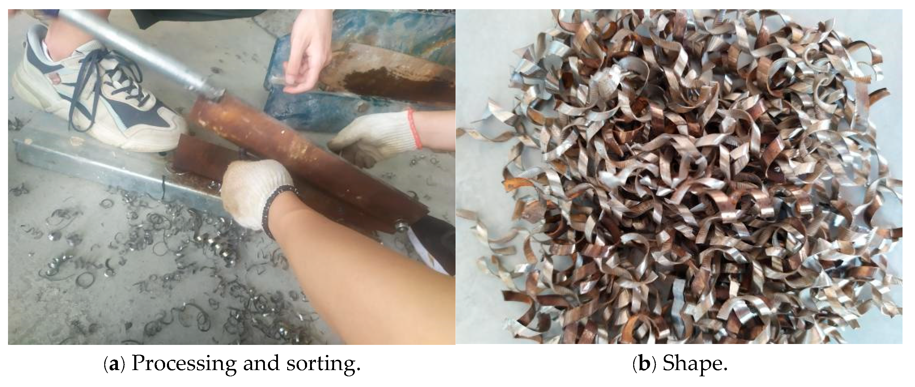
2.1.2. Waste Steel Fibers

The waste steel fibers used in the test were obtained from mechanically processed filaments with a three-dimensional spiral shape. Due to the different lengths of the WSFs, they were cut into finished products with a length of 10–30 mm, with an average length of 25 mm, and then rust and oil stains were removed and they were dried for use [51]. After measurement, the average size of the waste steel fibers was 0.36 mm (thickness) × 2.68 mm (width), the average tensile strength was 385.3 MPa, and the elastic modulus was 2.02 × 10⁵ MPa. The volume contents of waste steel fiber in concrete were 0, 0.5%, 1.0%, and 1.5%. The sorting process and shape of the waste steel fibers are shown in Figure 1.

2.1.3. Concrete

The design of the concrete mix ratio is shown in Table 2, which is divided into two strength grades of C30 and C50. Three groups of samples were retained when the specimens were poured, and the sample size was 100 mm × 100 mm × 100 mm. After 28 days of standard curing, the cube compressive strength tests were carried out, and the average value of the three test blocks was taken as the test value. The results are shown in Table 3.

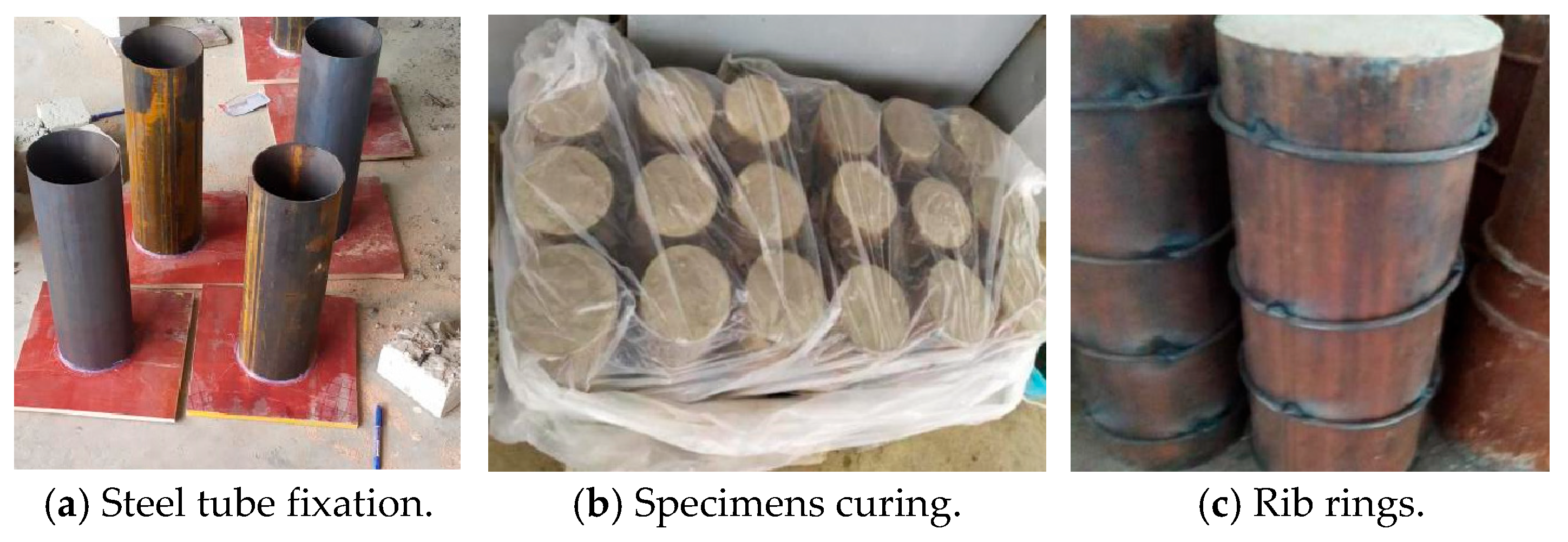
2.2. Specimens’ Manufacture and Curing

A total of 17 ERWCFST and 1 high-strength external steel rib ring restraint waste-steel-fiber-reinforced concrete filled steel tube (HERWCFST) columns were designed. The steel tubes were processed by laser cutting, which can ensure the flatness of both ends and prevent the leakage of concrete during pouring. The processed steel tubes were bonded with the bottom plate by hot-melt adhesive, and then the concrete was poured inward. When pouring concrete, the stirring rod was inserted and compacted. The specimens were placed in a dry and cool place, and the top of the concrete-filled steel tubes was covered with plastic film [52]. The specimens were cured under natural conditions for more than 28 days until the concrete reached the design strength, and the external rib rings were welded. Figure 2 shows the production and curing of the specimens. The specific design parameters of each specimen are shown in Table 4.

2.3. Testing Process

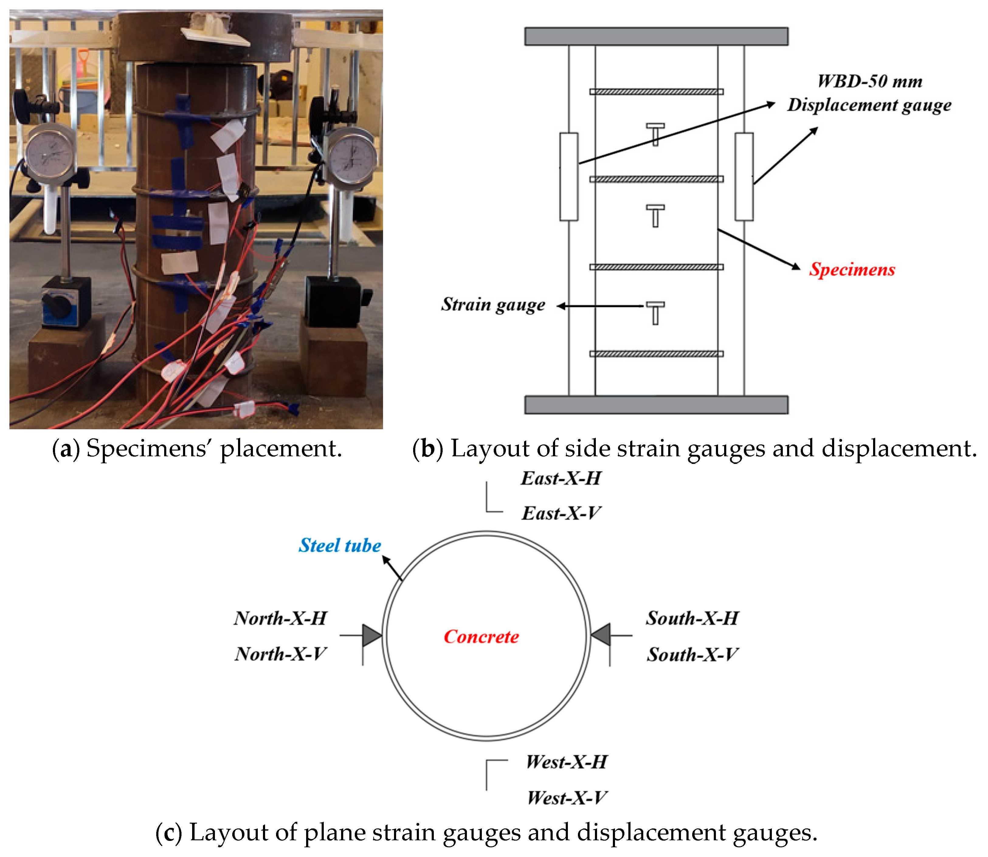
2.3.1. Loading Equipment and Measuring Point Arrangement

The test was carried out on the YAE-10000 (10 MN) electro-hydraulic servo long column pressure testing machine, and the plate hinge was used for loading. Displacement sensors and 30 mm thick steel pads and acrylic plates were placed on the pads and specimens, and the loading device is shown in Figure 3. The test equipment included the electro-hydraulic servo long column pressure testing machine, a DH3818-2 static data acquisition box, a displacement sensor, a dial gauge and computer, and so on.

2.3.2. Loading System

The loading of the specimens was controlled by the load–displacement joint control, which was divided into two stages: preloading and formal loading. Preloading was completed according to the axial load being less than 10% of the peak load, and the working conditions of the testing machine and the specimen were checked. If the installation error of the specimen was large, real-time adjustment was performed, and then the specimen was unloaded. We initialized the test system, and the preloading work was completed. The formal loading was completed in two stages: In the first stage, load control was adopted. The load increment of each grade was 10% of the peak load, and the load was loaded to 80% of the peak load. Each grade was loaded and collected after the data were stable, and then the next stage was loaded. In the second stage, the displacement control was adopted, and the loading rate was 2 mm/min. After each grade of loading was completed, the data were collected stably. When the axial load dropped to 20% of the peak load or the axial compression deformation exceeded 5% of the specimen, the loading as stopped and the test was completed.

3. Results and Discussion

3.1. Deformation Process and Failure Mode

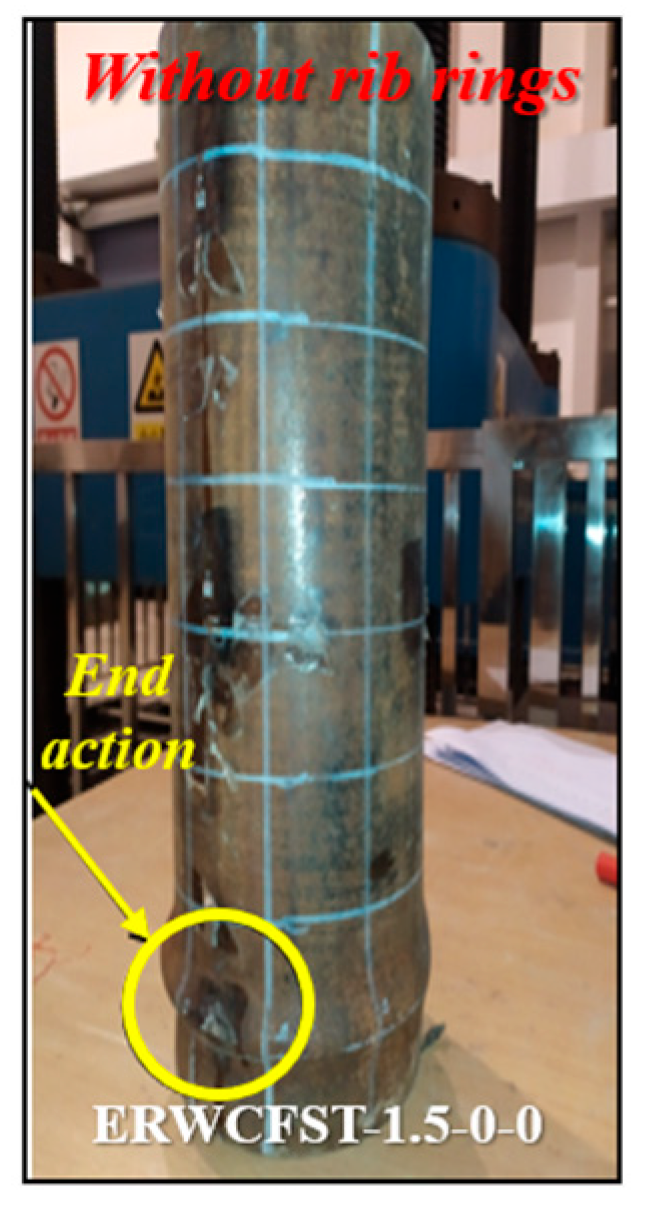
3.1.1. Specimens Without Rib Rings

Figure 4 shows the final failure mode of specimen ERWCFST-1.5-0-0. When the load reached 750 kN, the longitudinal strain in the middle of the steel tube reached the yield strain. The peak bearing capacity of the specimen was 837 kN, and the compressive deformation of the column was 2.8 mm. When the compression deformation of the column reached 5.5 mm, a slight bulge appeared at the end of the steel tube, and the specimen entered the strengthening stage. When the compression deformation of the column reached 21.6 mm, the end of the steel tube bulged seriously, and the axial force of the specimen decreased to 85%, and the test ended.
Due to the end action caused by the large axial load and friction at the interface between the loading plate and the specimen column, the specimen HERWCFST-1.5-0-0 showed obvious buckling failure. The steel tube could not resist the rapid increase in lateral expansion due to the unconfined constraint of the steel tube column. The buckling mainly occurred near the bottom of the specimen, and the steel tube was seriously buckled.

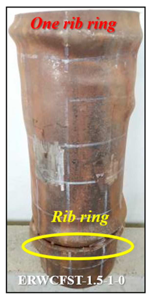
3.1.2. Specimens with Only One Rib Ring at the End

Figure 5 shows the final failure mode of specimen ERWCFST-1.5-1-0. At the initial stage of loading, the specimen was in the elastic stage. When the load reached 684 kN, the upper part of the steel tube column entered the yield stage at 26 mm from the top. When the load reached 688 kN, the longitudinal strain in the middle of the steel tube reached the yield strain. The compressive deformation of the column was 3.75 mm when the peak load of the specimen was 912 kN. When the compression deformation of the column reached 4.5 mm, a slight bulge appeared on the upper part of the rib ring of the specimen, and the specimen entered the strengthening stage. When the compression deformation of the column reached 28.7 mm, the upper part of the rib ring of the specimen bulged seriously, and the bottom bulge intensified. When the compression deformation of the column reached 32 mm, the specimen bulged seriously, the steel tube rib ring did not tear, and the axial force of the specimen decreased to 85%, signifying the end of the test.
ERWCFST-1.5-1-0 showed obvious buckling failure, and the buckling position mainly occurred in the middle and bottom, without lateral restraint. The effective lateral restraint was provided at the steel tube with the additional rib ring, which limited the development of bulging and made the buckling occur at the upper and lower parts of the rib ring. Under large axial deformation, the concrete expanded and squeezed laterally after crushing, resulting in buckling of the steel tube.

3.1.3. Specimens with Only One Rib Ring at the Top and End

Figure 6 shows the final failure mode of specimen ERWCFST-1.5-2-50e. When the load reached 766 kN, the longitudinal and transverse strains in the middle of the steel tube reached the ultimate strain. The peak bearing capacity of the specimen was 1021 kN, and the compressive deformation of the column was 3.8 mm. When the compression deformation of the column reached 5.1 mm, a slight bulge appeared in the middle of the column, and the specimen entered the strengthening stage. When the compression deformation of the column reached 27 mm, the middle and upper parts of the column were seriously buckled, and the outer part of the steel tube column underwent shear-type buckling. When the compressive deformation of the column reached 34.3 mm, shear slip lines formed in the middle and lower parts of the steel tube surface. The axial force of the specimen decreased to 85%, and the test was over.
ERWCFST-1.5-2-50e showed shear failure. Two shear slip lines were formed at the outer surface of the middle and lower parts of the specimen, which were destroyed. The reason for this was that the core concrete was under the action of axial force. The combined effect of lateral expansion and longitudinal compression formed a shear slip line. The transverse restraint provided by the end rib ring of the specimen prevented any obvious buckling deformation at the bottom of the column.

3.1.4. Specimens with Multiple Rib Rings

Table 5 shows the yield load and the number of compressive deformations of the specimens with multiple rib rings, the compressive deformation values when the specimens were strengthened, the corresponding compressive deformation values when the steel tubes had bulge buckling and the bulging stopped, the compressive deformation values when the specimens were destroyed, and the peak load and failure mode of the specimens.
According to the data analysis in Table 5, the yield load and peak load of the specimens with multiple rib rings are higher than those of the specimens without rib rings, and also higher than those of the specimens with only one rib ring and the specimens with rib rings at the end, indicating that the setting of multiple rib rings plays a role in improving the bearing capacity of the column. Figure 7 shows the failure pattern of the specimens with multiple rib rings. ERWCFST-1.5-2-100 with multiple rib rings had a minimum yield load of 775 kN, a maximum peak load of 956 kN, a buckling compression deformation of 2.9 mm, and a compression deformation of 27.2 mm when the specimen failed. The failure mode was buckling failure, as shown in Figure 7a. Among all of the specimens with multiple rib ring constraints, the bearing capacity and deformation of ERWCFST-1.5-2-100 were the smallest.
When the amount of waste steel fiber and the number of restrained rib rings were fixed, the yield load of the specimens increased with the increase in the rib ring spacing. Compared with ERWCFST-1.5-3-50, the yield load of ERWCFST-1.5-3-75 and ERWCFST-1.5-3-100 increased by 4.1% and 11.9%, respectively, and the peak load increased by 3.3% and 4.7%, respectively. The compressive deformation of the post-buckling strengthening was very small, at 6.4% and 9.7%, respectively. The increase in the compressive deformation of the column was 0.7% and 5.2%, respectively, when the column was bent, and the increase in the compressive deformation of the column was 3.1% and 4.8%, respectively, when the column failed.
The failure modes of the three specimens were the same, i.e., the buckling failure of the steel tube, as shown in Figure 7c–e. It can be seen that the circumferential restraint capacity of the steel tube became stronger, and that the bearing capacity and ductility were enhanced by the scattered setting of rib ring. The reason for this is that the dispersed rib ring constraints make the two edge rib rings closer to the column end, so that the local compressive buckling of the column end due to the loading equipment is constrained, thereby improving the bearing capacity and ductility of the column.
When the number and spacing of rib rings were the same, the yield load and peak load of the specimen with no waste steel fiber, ERWCFST-0-4-100, were the smallest, while the yield load and peak load of the other three specimens increased. Compared with ERWCFST-0-4-100, the yield load of ERWCFST-0.5-4-100, ERWCFST-1.0-4-100, and ERWCFST-1.5-4-100 increased by 3.6%, 4.0%, and 7.5%, respectively, and the peak load increased by 2.9%, 6.3%, and 10.4%, respectively. The compressive deformation of the four specimens after buckling was very small, at about 3.9 mm. The compressive deformation of the column when buckling occurred was about 15 mm, and the compressive deformation of the column when it was destroyed was about 35 mm. Only the compressive deformation of ERWCFST-1.5-4-100 reached 40.3 mm. The failure modes of the four specimens were the same, i.e., the buckling failure of the steel tube, as shown in Figure 7h–k. It can be seen that when the rib ring constraint parameters are fixed, the incorporation of waste steel fiber can improve the bearing capacity of the column, but the improvement in ductility is limited. The reason for this is that, although the waste steel fiber enhances the strength and ductility of the concrete, the hoop effect of the steel tubes and rib rings is stronger, which makes it difficult to significantly enhance the ductility of the concrete.
When the amount of waste steel fiber and the spacing of the constrained rib rings were the same, with the increase in the number of rib rings, the parameters of the specimens under axial compression changed obviously. Compared with ERWCFST-1.5-3-75, the yield load of ERWCFST-1.5-4-75 and ERWCFST-1.5-5-75 increased by 13.0% and 9.0%, respectively, and the peak load increased by 8.6% and 11.1%, respectively. The compressive deformation of post-buckling strengthening decreased by 6.1% and 22.7%, respectively. The compressive deformation of the column first decreased and then increased when the buckling occurred, and the decrease and increase reached 15.0% and 17.6%, respectively. The increase in compressive deformation at column failure was 1.7% and 5.5%, respectively. The failure modes of the three specimens were the same, i.e., the buckling failure of the steel tube, and the parameters of the three specimens all decreased first and then increased. When the spacing of the three rib rings was 75 mm in the middle of the column, the constraint effect of the rib rings was weak due to the distance from the loading end, and the bearing capacity and ductility were the lowest among the three specimens. When four rib rings were set, the rib rings at both ends were closer to the loading end, forming effective constraints on the buckling part, improving the yield load and peak load of the specimens, and enhancing the ductility of the specimens. When the number of rib rings increased to five, due to the existence of more constraints on the outer convex buckling of the steel tube, the peak load increased obviously, and the compressive strength of the concrete was also improved, as was the compressive bearing capacity. However, as the number of rib rings continued to increase, the axial pressure at the top of the column became too large, and the outer convexity of the steel tube caused the top rib ring to break and lose its function, as shown in Figure 7m, so that the yield and strengthening strain decreased. Because the constraint of the top rib ring was weakened, the column was constrained by five rib rings, so the ductility of the column began to recover or even increase, meaning that the compression of the column increased when the final failure occurred.

3.1.5. Discussion of the Failure Modes

After setting the external rib ring constraints, the steel-reinforced concrete column body was strengthened, and the components mainly exhibited bulging failure. Only specimen ERWCFST-1.5-2-50e exhibited shear failure, forming shear slip lines at the middle and lower parts. The steel ring at the end of the specimen provided lateral restraint without significant damage, and without any restraining components, the end damage was significant. During the compression process of the specimen, there was no significant change before the peak load. After the peak load, local bulges began to appear in the unconstrained area, and the bulges were concentrated between the rib rings until the end of loading.
The restrained steel ring provided effective lateral restraint for the steel pipe, limiting the lateral expansion of the concrete and steel pipe, and buckling occurred between adjacent rib rings. This reduced the effective length of column buckling, thus improving the axial bearing capacity. However, for steel pipe columns without lateral constraints, there was a significant axial load at the interface between the loading plate and the specimen column, causing the concrete inside the specimen to expand and compress under significant axial loads, resulting in buckling failure.

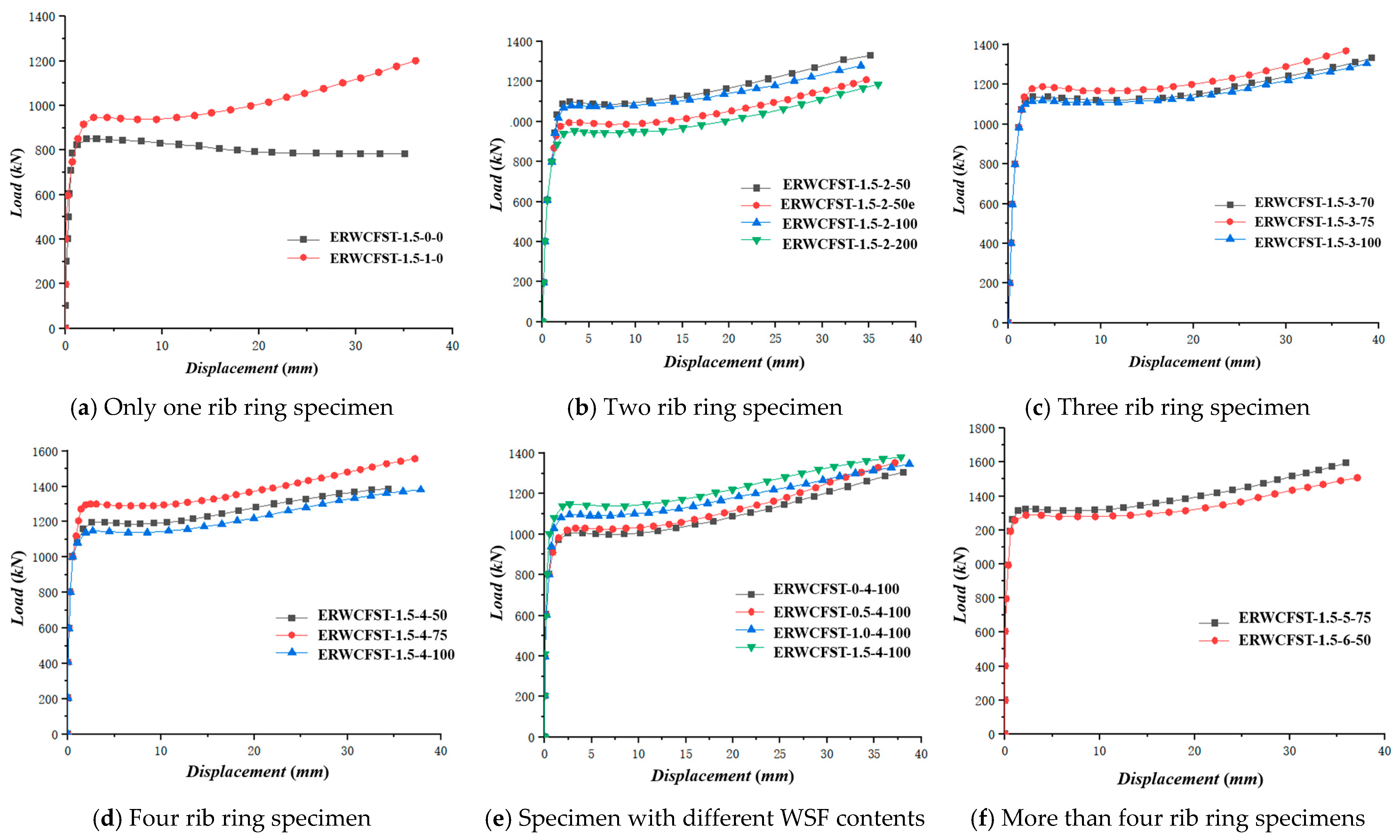
3.2. Load–Displacement Curve

According to the load–displacement data of the test, the load–displacement curves of the 18 specimens are shown in Figure 8. Among them, the displacement was averaged by two WBD displacement meters, and the load was automatically recorded by the testing machine.
At the initial stage of loading, the specimens were in the elastic stage, and the axial compression load increased linearly with the displacement. The restrained rib rings and waste steel fibers had little effect on the curve of the specimens, and the rising section of the curve of each specimen was essentially coincident. After entering the elastic–plastic stage, with the increase in the axial compression deformation of the specimens, the columns with rib rings were obviously different from the ordinary concrete-filled steel tube column. The bearing capacity of the columns with rib rings continued to increase with the displacement, while the axial compression load of the column without the rib rings reached the peak value, indicating that the bearing capacity of the columns with rib rings was significantly improved. In the post-elastic–plastic section of specimens, because the specimens continued to be subjected to axial compression loading, the concrete first reached the ultimate bearing capacity, at which point micro-cracks appeared and the strength degraded, resulting in part of the bearing capacity turning to the steel tube, resulting in a slight decrease in the axial bearing capacity of the specimens.
After the elastic–plastic stage, the concrete column was constrained by waste steel fibers, and the crack development was limited. The steel tube and concrete re-entered the common working stage; that is, the column entered the strengthening stage. After reaching the peak load, the steel tube could not provide effective lateral restraint for the column without rib rings, because the core concrete reached the ultimate strain. Therefore, after the specimen ERWCFST-1.5-0-0 reached the peak load, the load continued to decrease with the increase in displacement until the specimen failed, as shown in Figure 8a. After the columns with rib rings reached the peak load, the load in the elastic–plastic stage decreased slightly. Because the rib rings set on the outer surface of the steel tubes began to provide effective lateral restraint for the steel tubes, they limited the development of the surface buckling of the steel tubes, enhanced the axial bearing capacity of the specimens, and limited the fracturing and lateral expansion of the concrete. The steel tubes finally entered the strengthening stage, so the bearing capacity increased with the increase in compression deformation until the specimen was destroyed, as shown in Figure 8b–f.

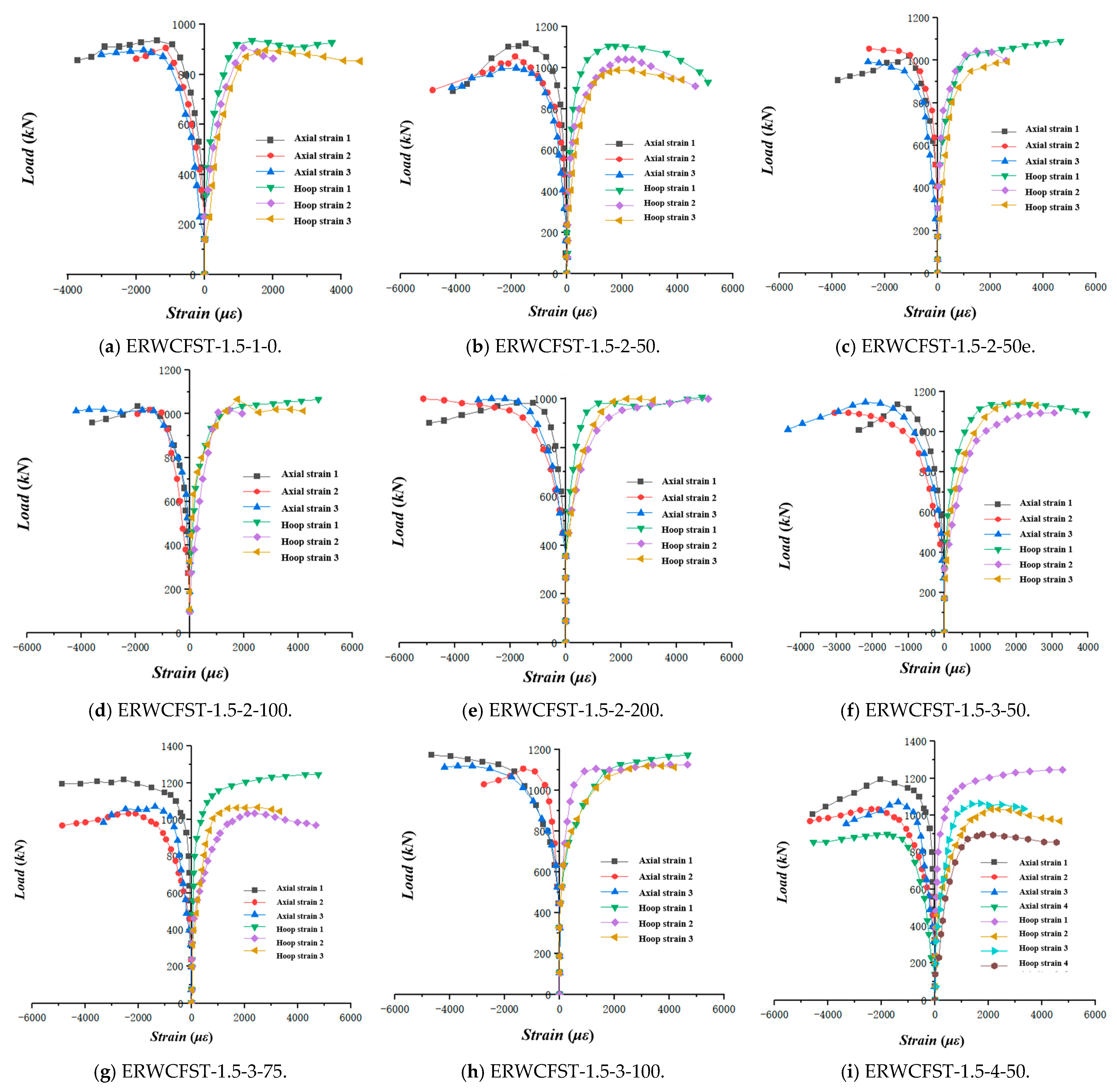
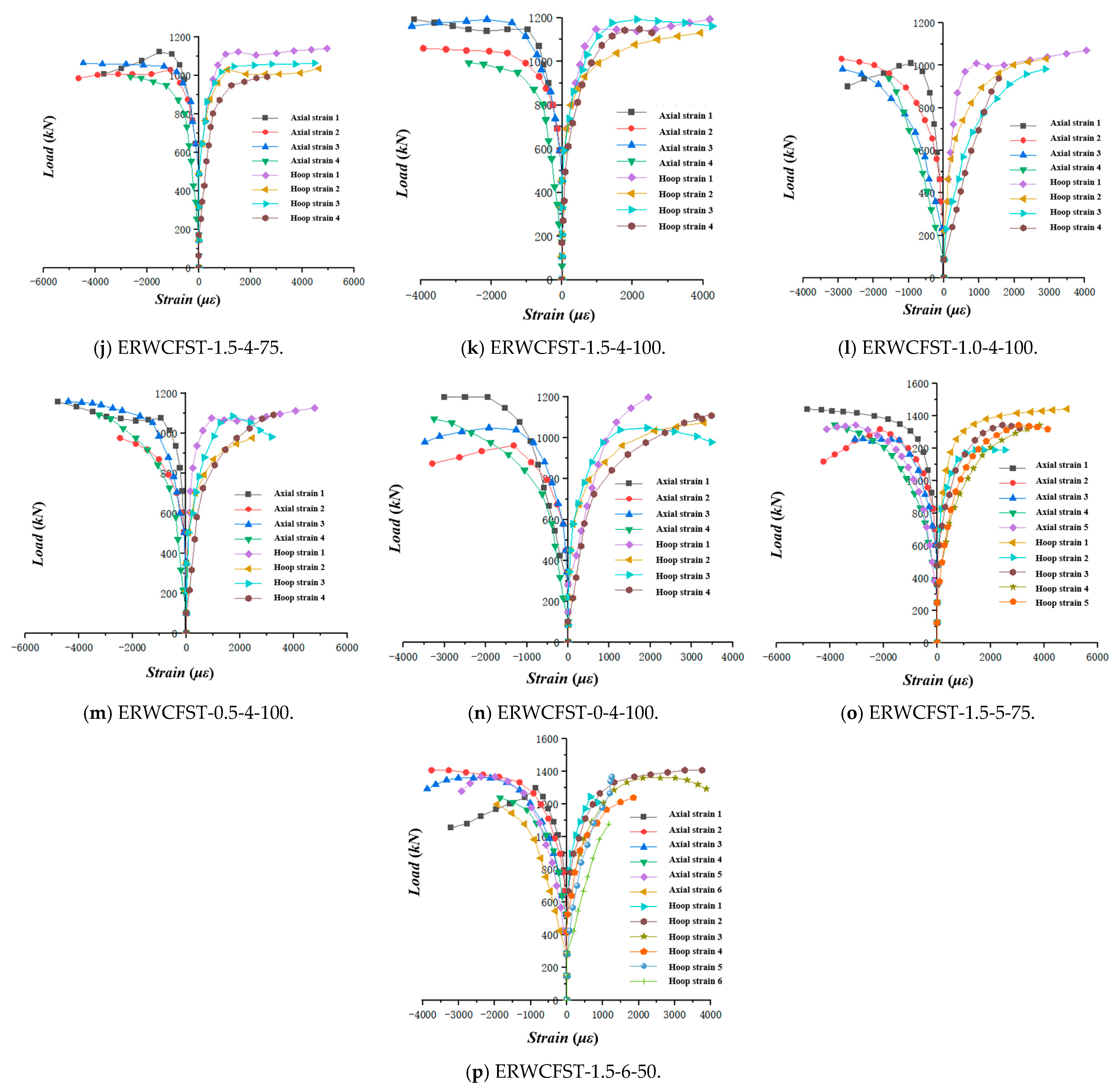
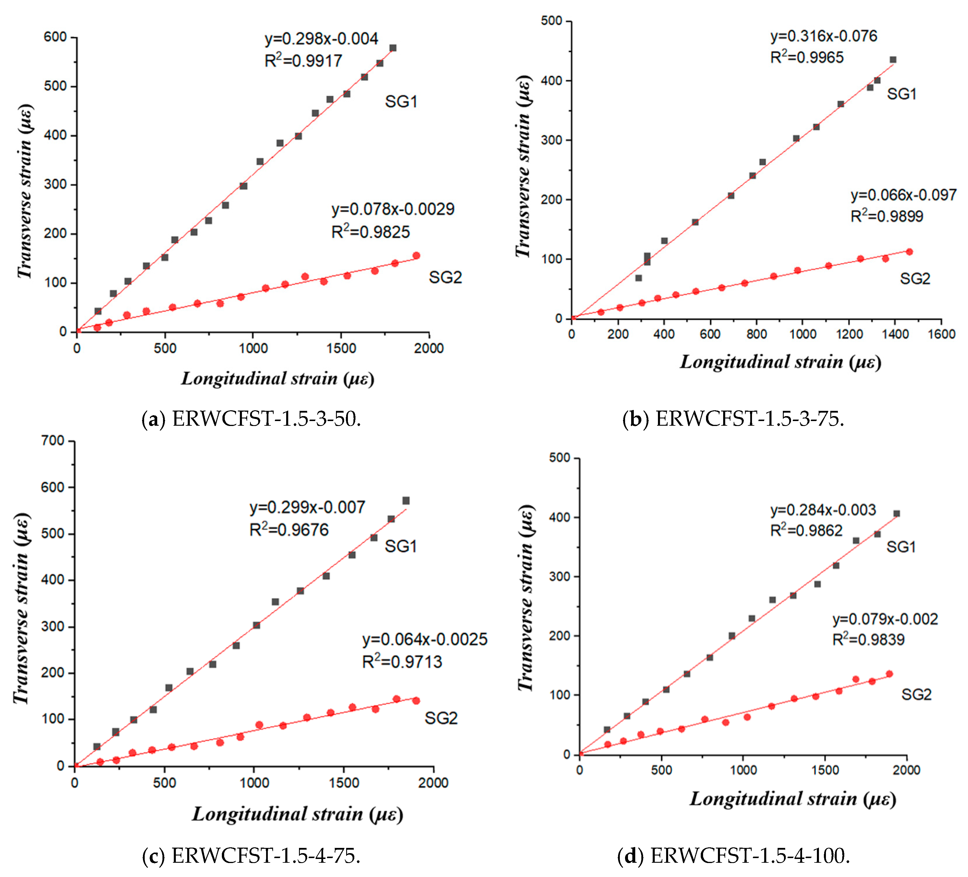
3.3. Load–Strain Curves

The axial and hoop load–strain curves of the steel tube columns are shown in Figure 9. It is stipulated that the hoop tensile strain is positive and the axial compressive strain is negative. In the early stage of loading, the influence of the rib ring constraints on the strain of the components was not obvious, and the development trends of the load–strain curve of each specimen were similar. After the axial compression load reached the peak, there was a significant difference in the strain of the specimens with and without rib rings. After the peak load, the strain curve of the specimen without rib rings continued to decline rapidly, and the decline period of the curve was very short. However, after the peak load of the specimens with rib rings, the bearing capacity of the column decreased briefly and then entered the strengthening stage quickly; that is, the bearing capacity and ductility of the column were improved.
The reason for the above phenomenon is that, after the column reached the peak load, due to the continuous increase in the strain of the steel tube, the hoop effect of the waste steel fiber concrete was more obvious, and the concrete also limited and delayed the buckling deformation of the steel tube, so the column changed from elastic to elastic–plastic. When the axial compression load of the column increased, the waste-steel-fiber-reinforced concrete reached the ultimate strain, and the cracks in the concrete penetrated each other, resulting in the decrease in concrete strength and stiffness degradation. At this time, the load borne by the waste-steel-fiber-reinforced concrete was transferred to the steel tube, which led to the increase in the deformation of the steel tube. Therefore, the column decreased after reaching the peak load. However, with the increase in the strain of the steel tubes, the rib rings set on the outer surface of the steel tubes began to provide effective lateral restraint, which limited the development of the steel tubes’ buckling, enhanced the axial bearing capacity of the specimens, and effectively limited the continuous cracking of waste steel concrete and the increase in lateral strain. Therefore, the column strain changed from attenuation to strengthening, the specimens entered the strengthening stage, and the strain curves were extended.

3.4. Splitting Tensile Strength

The constraint coefficient can reflect the bonding performance and geometric physical characteristics between steel and concrete. Due to the welding of the rib rings outside the steel tubes, the rib rings provide a constraint for the steel tube and concrete, and the ordinary hoop coefficient cannot reflect its constraint effect on the material. Therefore, this study introduces the transverse deformation coefficient and constraint index of steel tube to consider the constraint effect of the outer steel tubes and rib rings on concrete.
In order to study the performance of the steel outer rib-ring-reinforced interface bonding and enhanced resistance to axial strain, the transverse deformation of the two materials was determined by summarizing and calculating the data of the strain gauges attached to the surface of the steel tube SG1 and the steel rib ring SG2. In order to ensure the accuracy of the test, the average value of the strain on the surface of the steel tube and the steel rib ring was used. The slope of the longitudinal and transverse strain curves in the initial elastic stage was used to represent the Poisson’s ratio of the sample; that is, εh/εv.
Table 6 shows a summary of the transverse deformation coefficients, where the constraint index θ is the most important parameter in the action of the steel tube and represents the ratio of the bearing capacity of the steel to the concrete. Due to the constraint stress of the steel rib ring on the concrete-filled steel tube, it has a significant effect on the strength of the specimen. The famous Von Mises yield criterion model was adopted: the combined effect of the confining pressure of reinforced concrete and steel tubes confined by external steel rings was considered. The definition of θ was extended, including the constraint effect of the rib rings, and Equations (1) and (2) were established. The transverse strain and axial strain curves of typical concrete-filled steel tube columns are shown in Figure 10.
θ = A s t σ s y A c f c
A s t = A s + π 4 d 2 π D S f y r σ s y
where As, Ac, and Ast represent the cross-sectional area of the steel tube, the concrete, and their sum, respectively; σsy, fyr, and fc are the yield strength of the steel tube, the yield strength of the rib ring, and the strength of concrete, respectively; d and D are the diameter of the steel ring and the steel tube, respectively; and S is the spacing of the rib rings.
From Table 6, it can be seen that the Poisson’s ratio of the steel tube column is about 0.3 and is larger than that of the concrete, while the Poisson’s ratio obtained for the concrete-filled steel tube column with rib rings is about 0.1 and is less than the initial Poisson’s ratio of the concrete. This is because, for the ordinary concrete-filled steel tube or the unconstrained area between the rib rings, the damage is in a state of buckling; for the columns with rib rings, the rib rings provide lateral restraint, which limits the lateral expansion of the column, and buckling always occurs between the rib rings. Therefore, the concrete between the rib rings in the axial plane is still working. The rib rings improve the interfacial bonding performance of the concrete-filled steel tubes, and the steel rib rings can effectively limit the transverse deformation of the core concrete and the steel tube.

4. Analysis of Factors Affecting Bearing Capacity

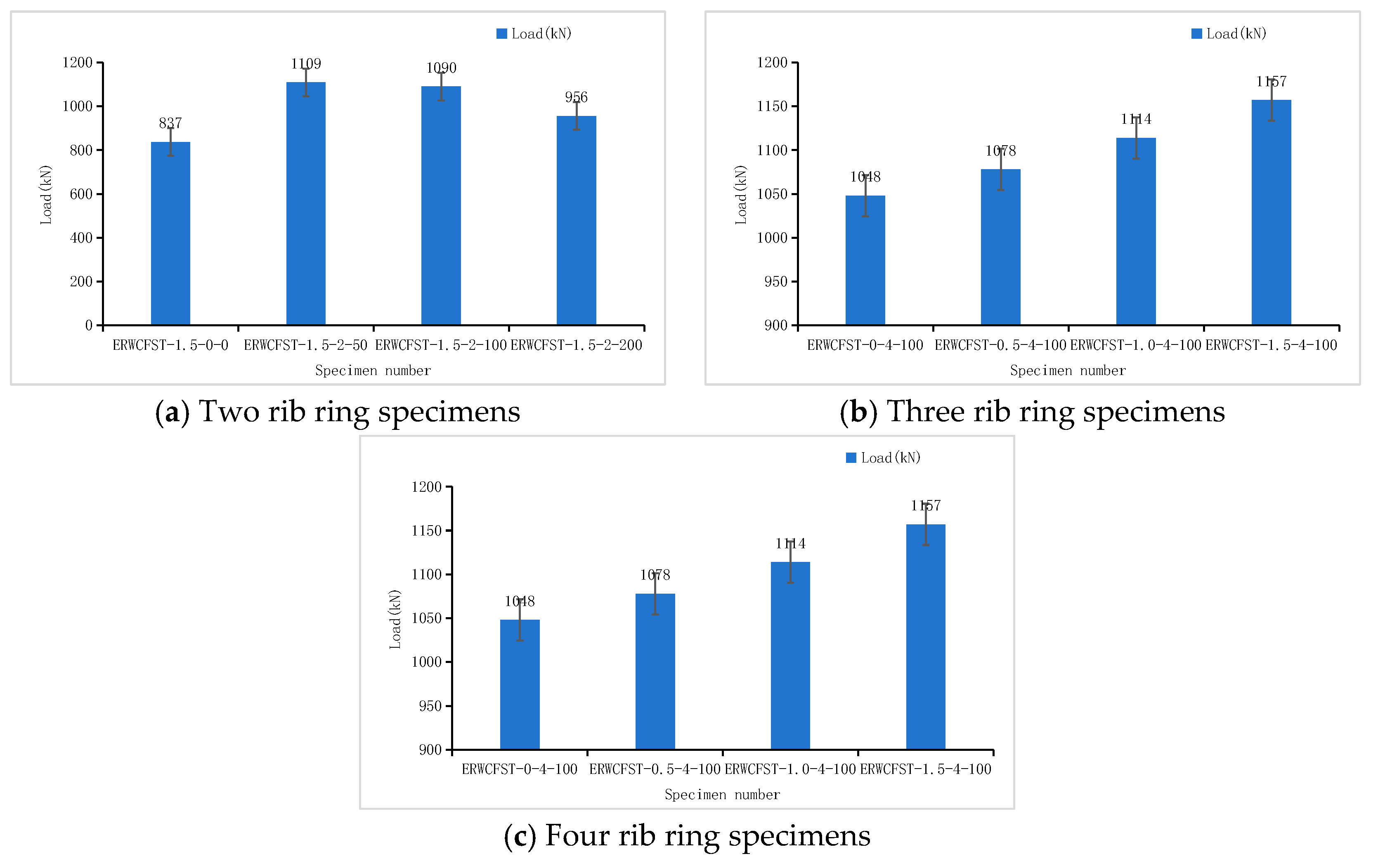
4.1. Rib Ring Number (N)

The bearing capacity curves for different numbers of rib ring constraints are shown in Figure 11. It can be seen from the figure that the bearing capacity increases linearly with the increase in the number of rib rings. When the spacing of the rib rings is constant, the bearing capacity of the columns with different numbers of rib rings is 32.5%, 21.98%, 24.61%, 40.86%, and 53.17% higher than that of the column without rib rings, respectively. Among them, the maximum increase rate of column ERWCFST-1.5-6-50 was 53.17%, with an average increase of 37.78%. Compared to the column without rib rings, the bearing capacity of ERWCFST-1.5-5-75 increased by 42.29%. Relative to the column with four rib rings, ERWCFST-1.5-5-75 exhibited the highest increase in bearing capacity, reaching 56.75%. In contrast, the maximum increase rate of ERWCFST-1.5-4-100 was 38.23%, with an average increase of 34.77%.
Due to the increase in the number of rib rings, more effective constraints are provided to the steel tube, which makes the interface bonding and stress distribution of the concrete-filled steel tube more uniform. When the axial load is applied, the confining pressure of the steel tube to the concrete is enhanced due to the lateral restraint, which improves the bearing capacity of the column and reduces the rate of load decline.

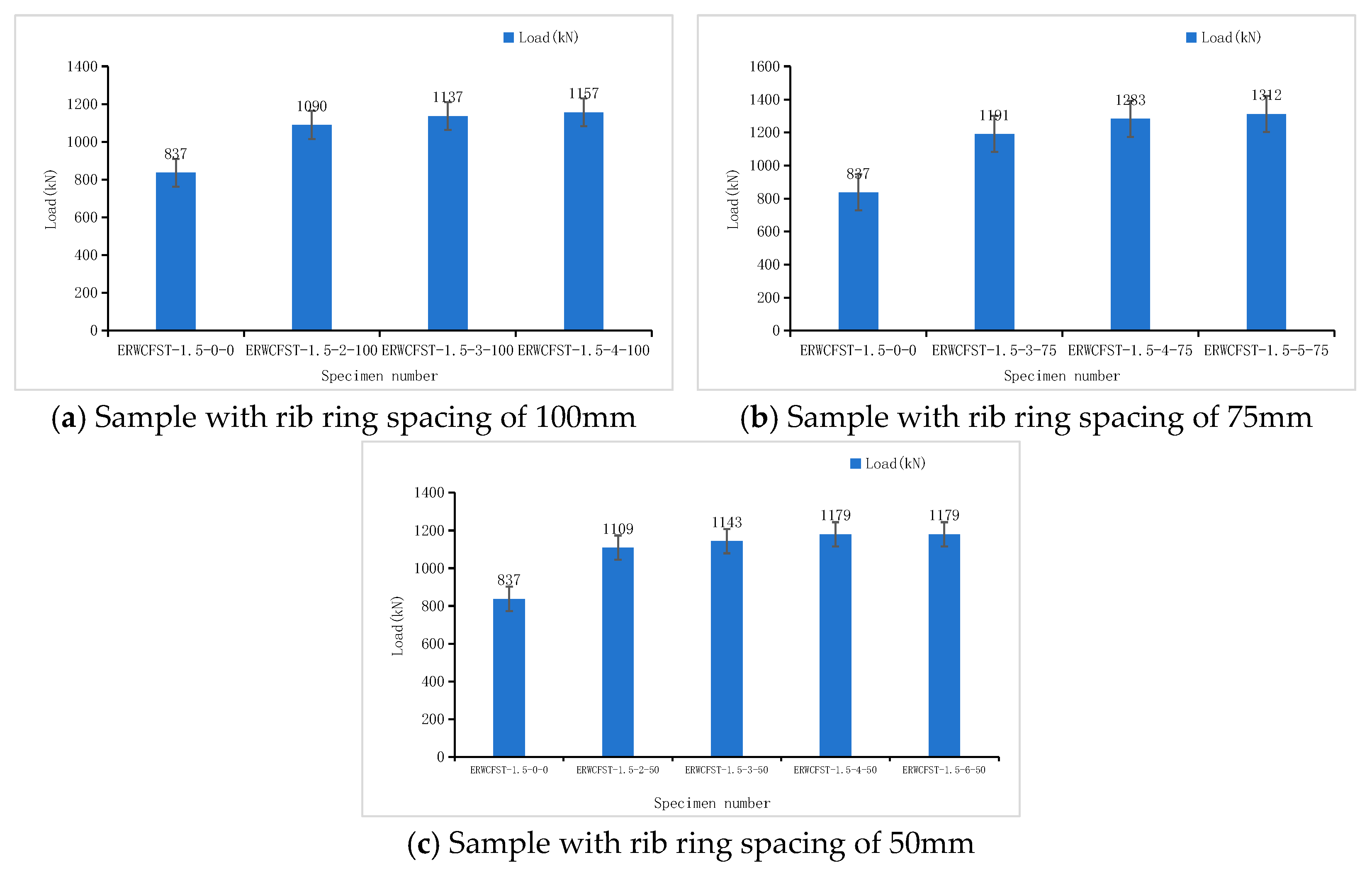
4.2. Rib Ring Spacing (S)

Figure 12 shows the influence of different spacing of the rib ring constraints on the bearing capacity. It can be seen from the figure that, with the increase in rib ring spacing, the bearing capacity of the column first increases and then decreases. Compared with the column without rib rings, the bearing capacity of the columns with two rib rings constantly improves, and when the distance between the two rib rings is 50 mm, the bearing capacity increases the most (35.2%). With the increase in the number and spacing of rib rings, it can be seen from the figure that the bearing capacity of the column with four rib rings and a spacing of 75 mm was 1283 kN, with the largest increase (53.29%).
Because the rib rings provide effective lateral restraint to the steel tube, the restraint effect on the specimens is different when the rib rings’ spacing is different. The rib rings provide effective constraints on the easily damaged ends and middle–upper parts of the column, the interface bonding and stress distribution of the specimens are more uniform, and the bearing capacity is improved more significantly.
However, it can be seen from the figure that the upward trend does not always exist. As the rib rings’ spacing increases, the bearing capacity also shows a downward trend. For example, for ERWCFST-1.5-2-200, where the rib rings’ spacing was large, the stress at the rib rings was the most concentrated, and the stress distribution in most areas without rib rings was not uniform. Under the action of large loads, when the yield point of the steel tube or concrete is reached, the column cannot resist its lateral constraint, resulting in serious buckling of the steel tube.
In summary, within a specific interval of rib rings, the application of axial load induces lateral restraint from the rib rings, thereby enhancing the confining pressure exerted by the steel tube on the concrete. This results in a more uniform distribution of forces within the column, which not only improves the strength of both the core concrete and the steel tube but also mitigates the risk of uneven stress distribution, which could lead to local buckling of the steel tube. Consequently, the axial bearing capacity experiences the most significant increase when the column height ranges from H/8 to H/4.

4.3. Rib Ring Position (S)

The comparative analysis of the bearing capacity of columns with different rib ring constraint positions is shown in Figure 13. According to the test results, the difference between the two is 10.52%. It can be seen that the position of the rib rings has an important influence on the experimental results.
When the rib rings’ strengthening points are located near the middle of the steel tube (ERWCFST-1.5-2-50), it is the constrained stress concentration part that effectively constrains the cracking deformation of the nearby core concrete. Under the action of load, the rib rings provide effective lateral restraint for the steel tube, and the buckling always occurs between the adjacent rib rings, which reduces the effective length of the column buckling, thus increasing the axial bearing capacity, and the bearing capacity is increased by 30.5%. However, the top and bottom of the rib rings lack effective lateral constraints, and a large amount of axial stress is transferred to the upper and lower parts of the steel pipe, thereby increasing the lateral deformation.
However, when the strengthening points of the rib rings are located at the ends of the steel tube (ERWCFST-1.5-2-50e), due to the lateral restraint of the rib rings, the end damage caused by axial load and friction is effectively alleviated, and the bearing capacity of the components is also improved. However, due to the uneven restraint stress, a large amount of stress turns to the zone without rib ring restraint under axial load, which makes the concrete more easily expand and break under the action of large axial deformation, and the bearing capacity of the middle–upper parts of the column height decreases. In contrast, the constraint effect of the components near the middle of the rib rings is more uniform, and the bearing capacity of the components is better.

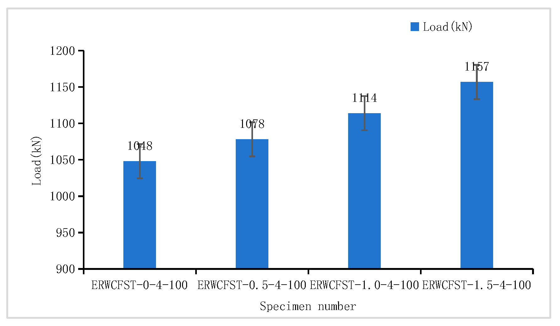
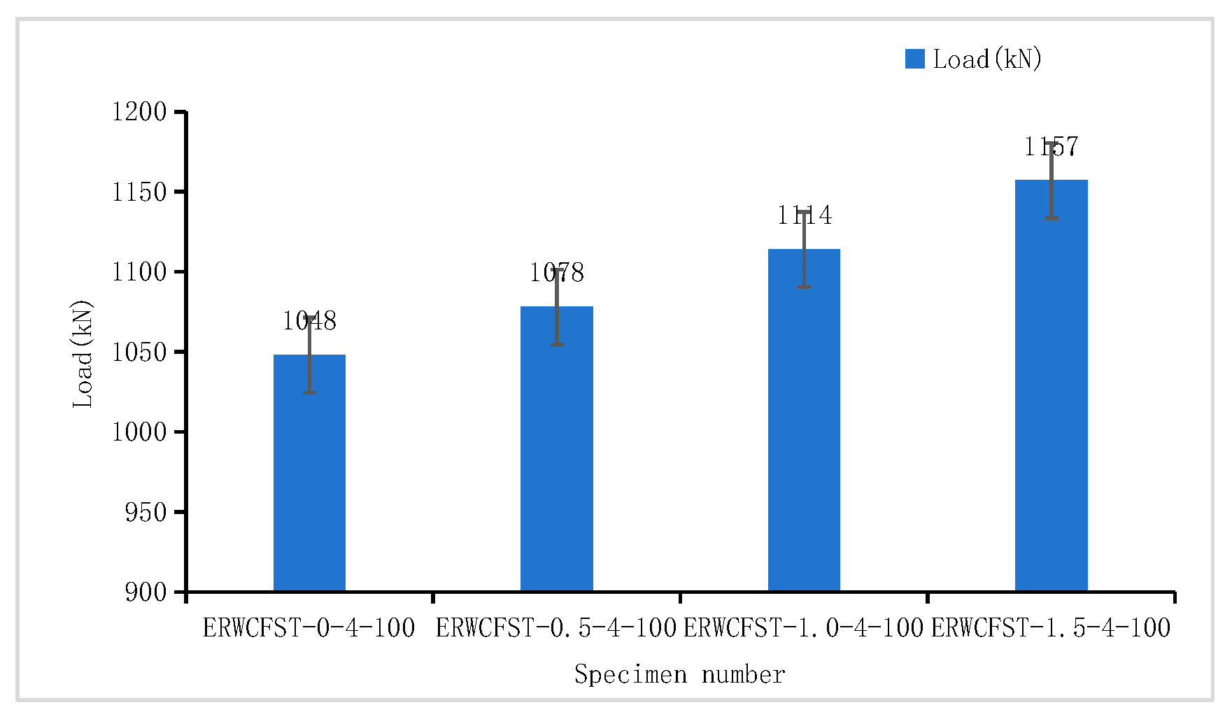
4.4. Waste Steel Fiber Content (S)

With the incorporation of waste steel fibers, the bearing capacity of the column increases to a certain extent (Figure 14). Taking the steel tube column with four rib rings and a spacing of 100 mm as an example, the bearing capacity of the column with 0.5–1.5% waste steel fiber content increased by 2.86%, 6.3%, and 10.4% respectively, compared with the steel fiber column without steel fiber, and the maximum increase rate was 10.4%. The waste steel fiber was embedded in the concrete, and the friction angle between the aggregates was increased due to the effect of the bolt, forming a complex three-dimensional spatial structure of the ring support, which effectively weakened the concentrated stress phenomenon at the cracks and defects, ensuring a strong connection inside the concrete, which played a role in cracking resistance and improving the cohesion of the concrete matrix. When the concrete is destroyed, the steel fiber skeleton structure delays the development of cracks. At the same time, when the force is pulled out from the concrete, it consumes a lot of energy, which delays the destruction of the concrete and releases the deformation of the concrete. Therefore, with the increase in the content of waste steel fiber, the bearing capacity and ductility of the column show an increasing trend. When the concrete is damaged, the waste steel fiber can significantly improve the ductility of the column.

4.5. Ductility of Specimens

Compared with ordinary concrete-filled steel tubes, waste-steel-fiber-reinforced concrete-filled steel tubes with rib rings have good ductility. In order to reflect the ductility of the specimens, the ductility index is expressed according to the curvature ductility μ (Equation (3)) defined in References [53,54,55,56].
μ = Δ N Δ ε = N 1 N 2 ε 1 ε 2
where N1 and N2 are the load values corresponding to the yield load value and the 0.05 strain after the peak value, respectively, while ε1 and ε2 are the strain values corresponding to the strain gauge measurements. The ductility calculation results of each specimen are shown in Table 7.
From the above table, it can be seen that the ductility index of concrete-filled steel tube columns with restrained rib rings is greater than that of ordinary concrete-filled steel tube columns. Due to the confining pressure of the steel tube and the rib rings on the concrete, under the condition of a certain number of constraints, reducing the rib rings spacing and changing the rib rings’ position cause a certain degree of increase in the ductility index of the column. Under the condition of a certain rib ring spacing, increasing the number of rib rings can also significantly increase the ductility index of the column. Therefore, the addition of rib rings can significantly improve the ductility of concrete-filled steel tube columns.

4.6. Calculation Formula of Axial Bearing Capacity

Based on the double-shear unified theory, considering the restriction of the restraining rib rings and the reinforcement of the steel fibers, the influence coefficient φ of the steel fibers was introduced. The axial bearing capacity of the concrete-filled steel tube column (Nu) can be calculated by referring to Equation (4):
N u = A s c f s c = A s c f c 1 + φ + k A s t 2 A c σ s θ + π d 2 2 D 2 T S f y r 1.212 + B A s σ s y A c f c + π 4 d 2 π D S f y r σ s y 1 A c f c + C A s σ s y A c f c + π 4 d 2 π D S f y r σ s y 1 A c f c 2
where D represents the outer diameter of the steel tube; T denotes the wall thickness of the steel tube; d signifies the diameter of the rib ring; and Ast, As, and Ac correspond to the cross-sectional areas of the steel (comprising the steel tube and steel rib ring), the steel tube alone, and the concrete, respectively. The variables σ, σsy, fyr, and fc represent the circumferential stress in the steel rib ring, the yield strength of the steel tube, the yield strength of the steel rib ring, and the compressive strength of the concrete, respectively. The parameter φ is associated with the characteristic parameters of steel fiber content; based on regression analysis and the Technical Code for Steel-Fiber-Reinforced Concrete Structures (CECS38: 2004), φ is determined by the equation φ = 1.8θ + 0.02λf. The calculation results are presented in Table 8.
It can be seen from the above table that the calculation results are generally large. The reason for this may be that the two coefficients of B and C were obtained by empirical regression. Due to the additional rib ring constraints used in this study, there may be weak stress areas in the material and constraint properties. Therefore, the calculation results of coefficients B and C are still too large. The calculation results are within the allowable range, with an average of 0.988 and a standard deviation of 0.072. The overall results are close and in good agreement. We calculated the mean absolute percentage error (MAPE = 1.8%), demonstrating high agreement between the predicted and experimental results.

5. Conclusions

This study presents a comprehensive investigation into the axial compressive behavior of innovative ERWCFST columns through experimental testing and theoretical analysis. The main findings, practical implications, and future research directions are summarized as follows:
(1)
Setting rib ring constraints outside the steel pipe significantly improves the mechanical performance of the column. Compared with traditional steel–concrete columns, the axial bearing capacity was increased by 32.5–53.17%. The performance of the column was optimal when the rib ring spacing was between H/8 and H/4 (50–100 mm), and the stress distribution of the steel tube was most uniform when the number of rib rings was greater than the column height-to-diameter ratio.
(2)
The addition of WSF to concrete effectively improves the performance of the columns after peak load. The ductility of all specimens increased by at least 10%, and the bearing capacity increased by 2.86–10.49%, showing excellent improvements in crack resistance and energy dissipation.
(3)
If the recommended number of rib configurations in this type of structural design is 4–6 and the rib ring spacing is greater than 100 mm, the diameter range of rib ring steel bars is 6–10 mm, and the optimal volume fraction of WSF is 1.0–1.5%.
(4)
Based on the Von Mises yield criterion, considering the interaction of the rib rings, steel tube, and concrete under three-dimensional stress states, a theoretical formula for calculating the axial compressive bearing capacity of external steel rib ring restraint waste-steel-fiber-reinforced concrete-filled steel tube was established according to the double-shear unified theory. The results were compared with the experimental results, and the two were in good agreement.
This research establishes ERWCFSTs as a promising solution that combines structural efficiency with sustainable material usage, while identifying clear pathways for further development. The findings provide both immediate design guidelines and a foundation for future innovation in composite structural systems.

Author Contributions

Conceptualization, Y.G.; methodology, Y.G.; software, X.R.; validation, X.R.; formal analysis, Y.L.; investigation, Y.L.; resources, J.G.; data curation, J.G.; writing—original draft preparation, J.G.; writing—review and editing, M.L. All authors have read and agreed to the published version of the manuscript.

Funding

This research was funded by the Jiangxi Province Intelligent Building Engineering Research Center Open Fund Project (No. HK20231009), the National Natural Science Foundation of China (51978088), and the State Key Laboratory of Geological Disaster Prevention and Geological Environmental Protection of Chengdu University of Technology, grant numbers 2015BAK09B01 and SKLGP2019K019.

Data Availability Statement

Data will be made available upon request.

Acknowledgments

The authors of the paper would like to thank the editors and reviewers for their guidance and feedback on this paper.

Conflicts of Interest

The authors declare that they have no known competing financial interests or personal relationships that could have appeared to influence the work reported in this paper.

References

  1. Kumar, S.; Gupta, P.K.; Iqbal, M.A. Experimental and numerical study on self-compacting alkali-activated slag concrete-filled steel tubes. J. Constr. Steel Res. 2024, 214, 108453. [Google Scholar] [CrossRef]
  2. Sepahvand, M.F.; Lenwari, A.; Young, B. Plastic seismic design of moment-resisting frames using concrete-filled steel tube columns. Eng. Struct. 2025, 322, 119225. [Google Scholar] [CrossRef]
  3. Van Cao, V. Behaviour of rectangular concrete-filled steel tube beams under monotonic and cyclic loadings. J. Constr. Steel Res. 2024, 220, 108816. [Google Scholar]
  4. Megahed, K.; Mahmoud, N.S.; Abd-Rabou, S.E.M. Finite Element Modeling for Concrete-Filled Steel Tube Stub Columns Under Axial Compression. Int. J. Steel Struct. 2024, 24, 1229–1250. [Google Scholar] [CrossRef]
  5. Sornam, I.A.; Dominic, J.R.J. Performance of lightweight coconut shell concrete-filled circular steel tube columns under axial compression. Mater. Res. Express 2024, 11, 085514. [Google Scholar] [CrossRef]
  6. Ahmad, S.; Kumar, A.; Kumar, K. Axial performance of GGBFS concrete filled steel tubes. Structures 2020, 23, 539–550. [Google Scholar] [CrossRef]
  7. Elghazouli, A.Y.; Mujdeci, A.; Bompa, D.V.; Guo, Y.T. Experimental cyclic response of rubberised concrete-filled steel tubes. J. Constr. Steel Res. 2022, 199, 107622. [Google Scholar] [CrossRef]
  8. Ghannam, M.; Song, T.Y. Fire Resistance Design of Concrete-Filled Steel Tube Stub Columns. Fire Technol. 2020, 57, 911–942. [Google Scholar] [CrossRef]
  9. Kenarangi, H.; Bruneau, M. Shear Strength of Composite Circular Reinforced Concrete-Filled Steel Tubes. J. Struct. Eng. 2020, 146, 04019180. [Google Scholar] [CrossRef]
  10. Ali, A.A.; Abbas, N.J. Behavior of Box Concrete-Filled Steel Tube Columns Considering Confinement Effect. Int. J. Steel Struct. 2021, 21, 950–968. [Google Scholar] [CrossRef]
  11. Kenarangi, H.; Bruneau, M.; Varma, A.H.; Ahmad, M. Simplified Equations for Shear Strength of Composite Concrete-Filled Steel Tubes. Eng. J.-Am. Inst. Steel Constr. 2021, 58, 197–221. [Google Scholar] [CrossRef]
  12. Mansouri, A. Shear Strength of Concrete-Filled Steel Tubes Based on Experimental Results. J. Struct. Eng. 2020, 146, 04020097. [Google Scholar] [CrossRef]
  13. Van Cao, V.; Trinh, T.M.N. Performance of circular concrete filled steel tubes after fire exposure: Experiments. Structures 2023, 55, 539–550. [Google Scholar]
  14. Nguyen, D.B.; Lin, W.S.; Liao, W.C. Long-Term Creep and Shrinkage Behavior of Concrete-Filled Steel Tube. Materials 2021, 14, 295. [Google Scholar] [CrossRef]
  15. Younas, S.; Hamed, E.; Li, D.X.; Uy, B. Eccentrically loaded concrete-filled steel tubes made with high strength materials. Eng. Struct. 2023, 275, 115246. [Google Scholar] [CrossRef]
  16. Gunawardena, Y.; Aslani, F. Static flexural behaviour of concrete-filled spiral-welded stainless-steel tubes. Thin-Walled Struct. 2020, 151, 106731. [Google Scholar] [CrossRef]
  17. Alatshan, F.; Osman, S.A.; Hamid, R.; Mashiri, F. Stiffened concrete-filled steel tubes: A systematic review. Thin-Walled Struct. 2020, 148, 106590. [Google Scholar] [CrossRef]
  18. Schurgacz, P.; Knobloch, M. Concrete-filled hollow section composite columns for multi-storey buildings—Innovation and design. Stahlbau 2023, 92, 155–172. [Google Scholar] [CrossRef]
  19. Xiamuxi, A.; Chen, H.L.; Liu, C.J. Flexural behavior of reinforced and recycled aggregate concrete-filled square steel tubes. J. Constr. Steel Res. 2024, 221, 108891. [Google Scholar] [CrossRef]
  20. Le, K.B.; Cao, V.V. Numerical Study of Circular Concrete Filled Steel Tubes Subjected to Pure Torsion. Buildings 2021, 11, 397. [Google Scholar] [CrossRef]
  21. Ayough, P.; Sulong, N.H.R.; Ibrahim, Z. Analysis and review of concrete-filled double skin steel tubes under compression. Thin-Walled Struct. 2020, 148, 106495. [Google Scholar] [CrossRef]
  22. Chaves, M.D.F.; Xavier, E.M.; Sarmanho, A.M.C.; Neto, J.G.R. Study of bolts used as shear connectors in concrete-filled steel tubes. Eng. Struct. 2021, 231, 111697. [Google Scholar] [CrossRef]
  23. Azad, S.K.; Uy, B. A numerical study on shear response of concrete-filled stainless steel tubes. Steel Compos. Struct. 2023, 48, 507–530. [Google Scholar]
  24. El Ouni, M.H.; Raza, A. Data-driven analysis of concrete-filled steel-tube CFRP-confined NSC columns. Mech. Adv. Mater. Struct. 2022, 29, 5667–5688. [Google Scholar] [CrossRef]
  25. Allouzi, R.A.; Almasaeid, H.H.; Salman, D.G.; Abendeh, R.M.; Rabayah, H.S. Prediction of Bond-Slip Behavior of Circular/Squared Concrete-Filled Steel Tubes. Buildings 2022, 12, 456. [Google Scholar] [CrossRef]
  26. Callejas, A.; Palma, R.; Hernández-Figueirido, D.; Rus, G. Damage Detection Using Ultrasonic Techniques in Concrete-Filled Steel Tubes (CFSTs) Columns. Sensors 2022, 22, 4400. [Google Scholar] [CrossRef] [PubMed]
  27. Younas, S.; Li, D.X.; Hamed, E.; Uy, B. Behaviour of high strength concrete-filled short steel tubes under sustained loading. Steel Compos. Struct. 2021, 39, 159–170. [Google Scholar]
  28. Abdalla, K.M.; Al-Rousan, R.; Alhassan, M.A.; Lagaros, N.D. Finite-element modelling of concrete-filled steel tube columns wrapped with CFRP. Proc. Inst. Civ. Eng.-Struct. Build. 2020, 173, 844–857. [Google Scholar] [CrossRef]
  29. Ghannam, M.; Hassan, M.K. Analysis of axial and rotational restrained concrete-filled steel tube columns at elevated temperature br. Eng. Struct. 2023, 278, 115568. [Google Scholar] [CrossRef]
  30. Kenarangi, H.; Bruneau, M. Investigation of Cyclic-Shear Behavior of Circular-Reinforced Concrete-Filled Steel Tubes. J. Struct. Eng. 2020, 146, 04020057. [Google Scholar] [CrossRef]
  31. Zhang, T.H.; Wang, Y.H.; Zhai, X.M.; Zhi, X.D.; Zhou, H.Y.; Yu, X. Impact response of stainless steel tube locally-strengthened by concrete-filled steel tube. Int. J. Impact Eng. 2024, 186, 104895. [Google Scholar] [CrossRef]
  32. Hassam, M.; Guo, L.H.; ul Haq, M.A.; Tahir, M. Strengthening schemes of special-shaped concrete-filled steel tubes: A review. Structures 2024, 63, 106417. [Google Scholar] [CrossRef]
  33. Miao, K.T.; Wei, Y.; Zhang, S.C.; Zheng, K.Q.; Ding, M.M. Eccentric compression behavior of concrete-filled steel tube columns strengthened by CFRP/steel strip. Eng. Struct. 2023, 287, 116191. [Google Scholar] [CrossRef]
  34. Liu, Z.N.; Lu, Y.Y.; Li, S.; Liao, J.C. Shear response of steel fiber reinforced recycled concrete-filled steel tube columns. Adv. Struct. Eng. 2021, 24, 2684–2704. [Google Scholar] [CrossRef]
  35. Huang, Y.; Zhao, P.T.; Lu, Y.Y.; Liu, Z.Z. Hysteresis performance of steel fiber-reinforced high-strength concrete-filled steel tube columns. J. Constr. Steel Res. 2024, 219, 108755. [Google Scholar] [CrossRef]
  36. Peng, K.D.; Yu, T.; Hadi, M.N.S.; Huang, L. Compressive behavior of hybrid double-skin tubular columns with a rib-stiffened steel inner tube. Compos. Struct. 2018, 204, 634–644. [Google Scholar] [CrossRef]
  37. Zeng, J.J.; Liang, S.D.; Zhuge, Y.; Zhou, J.K.; Liao, J.J. Seismic behavior of FRP-concrete-steel double skin tubular columns with a rib-stiffened Q690 steel tube and high-strength concrete. Thin-Walled Struct. 2022, 175, 109127. [Google Scholar] [CrossRef]
  38. Zakir, M.; Sofi, F.A.; Naqash, J.A. Compressive testing and finite element analysis-based confined concrete model for stiffened square FRP-concrete-steel double-skin tubular columns. J. Build. Eng. 2022, 44, 103267. [Google Scholar] [CrossRef]
  39. Zhou, X.H.; Zhou, Z.; Gan, D. Modeling of cyclically loaded square thin-walled CSFT columns stiffened by diagonal ribs using OpenSees. Thin-Walled Struct. 2023, 187, 110736. [Google Scholar] [CrossRef]
  40. George, C.; Selvan, S.S.; Kumar, V.S.; Murali, G.; Giri, J.; Makki, E.; Sathish, T. Enhancing the fire-resistant performance of concrete-filled steel tube columns with steel fiber-reinforced concrete. Case Stud. Constr. Mater. 2024, 20, e02741. [Google Scholar] [CrossRef]
  41. Shah, S.M.I.; Ganesh, G.M. Micro-Steel Fiber-Reinforced Self-compacting Concrete-Filled Steel-Tube Columns Subjected to Axial Compression. Int. J. Steel Struct. 2023, 23, 1031–1045. [Google Scholar] [CrossRef]
  42. Zhang, J.W.; Liu, X.; Kan, W.L.; Zhang, M.; Liu, J. Seismic Performance of Steel tube-reinforced Steel Fiber high-strength Concrete Columns with ultra-high Strength Steel Bars. J. Earthq. Eng. 2023, 27, 2088–2118. [Google Scholar] [CrossRef]
  43. Zhao, P.T.; Huang, Y.; Liu, Z.Z.; Wang, H.; Lu, Y.Y. Experimental research on seismic performance of steel fiber-reinforced recycled concrete-filled circular steel tube columns. J. Build. Eng. 2022, 54, 104683. [Google Scholar] [CrossRef]
  44. Kim, S.H.; Kim, H.J.; Lee, S.W.; Chung, K.S.; Choi, S.M. An Experimental Study on Shear Performance of Reinforced Steel Fiber Recycled Aggregate Concrete Filled Square Steel Tube Column of 50 MPa. Int. J. Steel Struct. 2022, 22, 1930–1941. [Google Scholar] [CrossRef]
  45. Zhao, P.T.; Huang, Y.; Liu, Z.Z.; Lu, Y.Y.; Wang, H. Experimental study on seismic performance of hybrid steel-polypropylene fiber-reinforced recycled aggregate concrete-filled circular steel tube columns. Constr. Build. Mater. 2022, 359, 129418. [Google Scholar] [CrossRef]
  46. Sakr, M.; Osama, B. Modeling of Ultra-high Performance Fiber Reinforced Concrete Filled Steel Tube Columns under Eccentric Loading. Period. Polytech.-Civ. Eng. 2022, 67, 20593. [Google Scholar]
  47. Zewdu, B.D.; Aure, T.W. Numerical Investigation of Carbon Fiber Reinforced Polymer Confined Concrete-Filled Steel Tube Columns under Eccentric Load. Adv. Civ. Eng. 2022, 2022, 4807436. [Google Scholar] [CrossRef]
  48. Karimi, A.; Nematzadeh, M. Axial compressive performance of steel tube columns filled with steel fiber-reinforced high strength concrete containing tire aggregate after exposure to high temperatures. Eng. Struct. 2020, 219, 110608. [Google Scholar] [CrossRef]
  49. Li, G.C.; Li, X.; Fang, C.; Wang, J.L.; Liu, R.Z. Dynamic behavior of concrete-filled steel tube cantilever columns stiffened with encased carbon fiber reinforced plastic profile subjected to lateral impact load. Int. J. Impact Eng. 2023, 177, 104561. [Google Scholar] [CrossRef]
  50. GB/T51446-2021; Standard of the People’s Republic of China. Technical Standard for Concrete-Filled Steel Tubular Hybrid Structures. China Architecture & Building Press: Beijing, China, 2021.
  51. Yan, J.Q.; Gao, Y.T.; Fan, T.; Xu, Q.; Yuan, W.G.; Zhao, X. Experimental Study on Flexural Performance of Recycled Steel Fiber Concrete Beams. Buildings 2023, 13, 3046. [Google Scholar] [CrossRef]
  52. Wang, B.; Lv, H.; Gao, Y.T.; Tang, M.G.; Ding, N.S.; Zhao, X.; Zhao, H.; Hu, X. Experimental Study on Axial Compressive Performance of Recycled Steel Fiber Reinforced Concrete Short Columns with Steel Pipes. Buildings 2024, 14, 2498. [Google Scholar] [CrossRef]
  53. GB50936-2014; Standard of the People’s Republic of China. Technical Code for Concrete Filled Steel Tubular Structures. China Architecture & Building Press: Beijing, China, 2014.
  54. GB/T 36024-2018; Standard of the People’s Republic of China. Metallic Materials—Test Method for Biaxial Tensile Strength of Thin Sheets and Strips with Cross Shaped Specimens. Standards Press of China: Beijing, China, 2018.
  55. GB/T228.1-2021; Standard of the People’s Republic of China. Metallic Materials-Tensile Testing-Part1: Method of Test at Room Temperature. Standards Press of China: Beijing, China, 2021.
  56. Cakmak, F.; Menkulasi, F. Evaluation of moment-curvature response and curvature ductility of reinforced UHPC cross-sections. Eng. Struct. 2024, 315, 118434. [Google Scholar] [CrossRef]
Figure 1. Waste steel fibers.
Buildings 15 02246 g001
Figure 2. Specimens’ manufacture and curing.
Buildings 15 02246 g002
Figure 3. Loading device and measuring point arrangement.
Buildings 15 02246 g003
Figure 4. ERWCFST-1.5-0-0 final failure mode.
Buildings 15 02246 g004
Figure 5. ERWCFST-1.5-1-0 final failure mode.
Buildings 15 02246 g005
Figure 6. ERWCFST-1.5-2-50e final failure mode.
Buildings 15 02246 g006
Figure 7. Specimens with multiple rib rings: final failure modes.
Buildings 15 02246 g007
Figure 8. Load–displacement curves.
Buildings 15 02246 g008
Figure 9. Load–strain curves.
Buildings 15 02246 g009aBuildings 15 02246 g009b
Figure 10. Typical transverse deformation coefficient.
Buildings 15 02246 g010
Figure 11. The bearing capacity of different numbers of restraint rib rings.
Buildings 15 02246 g011
Figure 12. The bearing capacity with different spacing of rib ring constraints.
Buildings 15 02246 g012
Figure 13. The bearing capacity of different constrained rib ring positions.
Buildings 15 02246 g013
Figure 14. The bearing capacity of different waste steel fiber contents.
Buildings 15 02246 g014
Table 1. Mechanical properties of steel tubes and steel bars.
Dimensions (D)
/mm
Yield Strength (fy)
/MPa
Ultimate Strength (fu)
/MPa
Elastic Modulus (E)
/×105 MPa
Poisson’s Ratio (v)
φ140 × 32513572.010.287
φ63004552.010.283
Table 2. Concrete design mix ratio (material consumption per unit volume, kg/m3).
WSF Volume Content (%)WSF Weight/kg/m3Cement/kg/m3Coarse Aggregate/kg/m3Sand/kg/m3Water/kg/m3
00339.61241.1639.3180.0
0.539.5339.61241.1639.3180.0
1.079339.61241.1639.3180.0
1.5118.5339.61241.1639.3180.0
Table 3. Calculation results of concrete compressive strength.
Concrete GradesAverage Compressive Strength (fcu)/MPaAxial Compressive Strength (fck)/MPa
C3033.522.445
C5055.837.39
Table 4. Design parameters.
Specimens
Number
H × d × tWSF Content/%Rib Rings Number (N)Rib Rings
Spacing (S)/mm
Concrete Strength Grade
ERWCFST-1.5-0-0400 × 140 × 31.50-C30
ERWCFST-1.5-1-0400 × 140 × 31.51-C30
ERWCFST-1.5-2-50400 × 140 × 31.5250C30
ERWCFST-1.5-2-50e400 × 140 × 31.5250C30
ERWCFST-1.5-2-100400 × 140 × 31.52100C30
ERWCFST-1.5-2-200400 × 140 × 31.52200C30
ERWCFST-1.5-3-50400 × 140 × 31.5350C30
ERWCFST-1.5-3-75400 × 140 × 31.5375C30
ERWCFST-1.5-3-100400 × 140 × 31.53100C30
ERWCFST-1.5-4-50400 × 140 × 31.5450C30
ERWCFST-1.5-4-75400 × 140 × 31.5475C30
ERWCFST-1.5-4-100400 × 140 × 31.54100C30
ERWCFST-1.0-4-100400 × 140 × 31.04100C30
ERWCFST-0.5-4-100400 × 140 × 30.54100C30
ERWCFST-0-4-100400 × 140 × 304100C30
ERWCFST-1.5-5-75400 × 140 × 31.5575C30
ERWCFST-1.5-6-50400 × 140 × 31.5650C30
HERWCFST-1.5-0-0400 × 140 × 31.5--C50
Note: The ERWCFST-M-N-S naming method was used to number each specimen, where M is the volume content of steel fiber, N is the number of rib rings, S is the spacing of the rib rings, and e is the setting of the rib rings at the end. For example, for ERWCFST-1.5-6-50, the waste steel fiber volume content is 1.5%, the outer side of the column steel tube welding has 6 rib rings, and the rib ring spacing is 50 mm on the concrete-filled steel tube column specimens.
Table 5. Axial compressive mechanical parameters of specimens with multiple rib rings.
Specimens
Number
Yield Load
/kN
Yield Deformation/mmPeak Load/kNStrengthening Deformation/mmDrum Deformation/mmStop Deformation/mmDeformation Maximum
/mm
ERWCFST-1.5-2-1008203.110905.814.125.835.8
ERWCFST-1.5-2-2007752.99566.821.523.227.2
ERWCFST-1.5-3-508892.811436.215.221.135.1
ERWCFST-1.5-3-759253.111816.615.325.836.2
ERWCFST-1.5-3-1009953.611976.815.930.936.8
ERWCFST-1.5-4-5010462.811795.915.127.533.9
ERWCFST-1.5-4-7510454.812836.213.224.836.8
ERWCFST-0-4-1009333.910485.315.927.934.2
ERWCFST-0.5-4-1009673.810785.714.126.135.6
ERWCFST-1.0-4-1009703.911146.215.827.835.2
ERWCFST-1.5-4-10010033.811575.715.233.740.3
ERWCFST-1.5-5-7510084.113125.117.930.138.2
ERWCFST-1.5-6-5011204.612825.322.935.839.3
Table 6. Summary of transverse deformation coefficients.
Specimen NumberConstraint Index/θSG1SG2
ERWCFST-1.5-1-01.490.3370.118
ERWCFST-1.5-2-501.820.3530.127
ERWCFST-1.5-2-50e1.660.3170.113
ERWCFST-1.5-2-1001.790.3290.108
ERWCFST-1.5-2-2001.570.3910.086
ERWCFST-1.5-3-501.870.2980.078
ERWCFST-1.5-3-751.950.3160.066
ERWCFST-1.5-3-1001.860.3040.081
ERWCFST-1.5-4-501.930.3370.109
ERWCFST-1.5-4-752.100.2990.064
ERWCFST-1.5-4-1001.720.2840.079
ERWCFST-1.0-4-1001.760.2810.077
ERWCFST-0.5-4-1001.820.2820.091
ERWCFST-0-4-1001.90.2790.103
ERWCFST-1.5-5-752.150.2800.073
ERWCFST-1.5-6-502.10.2680.078
ERWCFST-1.5-0-00.970.325-
HERWCFST-1.5-/-/0.940.318-
Table 7. Ductility index summary.
Specimen NumberSpacingN1ε1N2ε2μ
ERWCFST-1.5-0-0-8370.001589080.02680−2.81%
ERWCFST-1.5-1-0-9120.0016210360.02693−4.88%
ERWCFST-1.5-2-505011090.0016412920.02733−7.11%
ERWCFST-1.5-2-50D5010210.0016211770.02706−6.15%
ERWCFST-1.5-2-10010010900.0016212270.02705−5.39%
ERWCFST-1.5-2-2002009560.0016711170.02782−6.16%
ERWCFST-1.5-3-505011430.0015614360.02687−11.57%
ERWCFST-1.5-3-757511910.0015815480.02722−13.93%
ERWCFST-1.5-3-10010011370.0015815280.02726−15.23%
ERWCFST-1.5-4-505011790.0016315330.02673−14.09%
ERWCFST-1.5-4-757512830.0017316680.02833−14.47%
ERWCFST-1.5-4-10010011570.0016115040.02644−13.98%
ERWCFST-1.0-4-10010011140.0016714480.02738−13.00%
ERWCFST-0.5-4-10010010780.0017114010.02811−12.25%
ERWCFST-0-4-10010010480.0016213620.02655−12.61%
ERWCFST-1.5-5-757513120.0016617060.02717−15.43%
ERWCFST-1.5-6-505012820.0018516670.03037−13.49%
Table 8. Comparison of the calculated values (Nu) with the experimental values (Nexp) (kN).
Specimen NumberNexpNu3Nexp/Nu3
ERWCFST-1.5-1-09129310.98
ERWCFST-1.5-2-50110910871.02
ERWCFST-1.5-2-50D102110111.01
ERWCFST-1.5-2-100109010901.00
ERWCFST-1.5-2-2009569371.02
ERWCFST-1.5-3-50114311780.97
ERWCFST-1.5-3-75119112540.95
ERWCFST-1.5-3-100113711600.98
ERWCFST-1.5-4-50117911910.99
ERWCFST-1.5-4-75128313510.95
ERWCFST-1.5-4-100104810800.97
ERWCFST-1.0-4-100107810671.01
ERWCFST-0.5-4-100111411600.96
ERWCFST-0-4-100115711690.99
ERWCFST-1.5-5-75131213810.95
ERWCFST-1.5-6-50128212211.05
Average value 0.988
Standard deviation 0.072
Disclaimer/Publisher’s Note: The statements, opinions and data contained in all publications are solely those of the individual author(s) and contributor(s) and not of MDPI and/or the editor(s). MDPI and/or the editor(s) disclaim responsibility for any injury to people or property resulting from any ideas, methods, instructions or products referred to in the content.

