Abstract
This study investigates the effectiveness of strain-hardening cementitious composites (SHCC) reinforced with glass fiber (GF) mesh in enhancing the torsional behavior of reinforced concrete (RC) beams with circular openings. Eight full-scale RC beams were tested under pure torsion, including two control beams and six strengthened beams with varying configurations of horizontal, vertical, and combined SHCC-GF mesh retrofitting. The experimental program evaluated the influence of single- and double-layer GF mesh reinforcement on torsional capacity, crack propagation, stiffness, and energy absorption. The results demonstrated that the presence of an opening reduced the ultimate torsional capacity by 29%, elastic stiffness by 48%, and energy absorption by 64% compared to the solid control beam. Strengthening with horizontal SHCC strips restored 21–35% of the lost capacity, while vertical strips performed even better, achieving 44–61% improvement. The combined horizontal–vertical configuration with a double-layer GF mesh proved the most effective, increasing ultimate load by 91% compared to the unstrengthened beam with an opening. Finite element models (FEM) are developed using ABAQUS to simulate the performance of the tested beams.
1. Introduction
Integrating essential service lines—such as water supply, electrical wiring, and HVAC—through reinforced concrete (RC) beams is often carried out in multi-story buildings. However, this approach may introduce structural vulnerabilities, such as disturbing the stress distribution. When openings are pre-designed in compliance with engineering codes, they strike a balance between utility integration and structural safety. In contrast, unplanned core drilling, common during renovations or late-stage changes, requires thorough stress analysis and reinforcement [1,2]. The geometry of beam openings—whether circular, rectangular, or unconventional (e.g., triangular, diamond)—plays a critical role in structural response. Size classifications (“small” or “large”) dictate design approaches, with thresholds based on proportional depth: rectangular openings deeper than 25% of the beam’s total depth or circular openings exceeding 40% diameter qualify as “large.” Research by Mansur et al. [3] and Abul Hasnat et al. [4] further refines this by defining large openings as those longer than the top or bottom chord height. These distinctions are pivotal for predicting stress distribution and failure modes.
Given these geometric considerations and their impact on structural performance, implementing appropriate reinforcement is essential to alleviate stress concentrations and maintain the beam’s structural integrity. Openings often create localized edge stresses that can initiate premature cracking. These effects can be mitigated through internal reinforcement during casting or external retrofitting methods [5,6,7,8]. In beams subjected to torsional forces, these challenges become more pronounced, as torsion interacting with openings intensifies shear stresses and increases the likelihood of diagonal cracking and brittle failure [3,4,9,10]. Torsional failure is particularly critical due to its sudden and often uncontrollable nature, posing substantial safety risks. Torsion-induced shear stresses generate diagonal tensile strains that can lead to cracking; without adequate reinforcement, such members are vulnerable to abrupt, brittle collapse [11].
In modern structural engineering practice, several methods are commonly employed to strengthen reinforced concrete (RC) beams, including section expansion, external prestressing, and the use of externally bonded fiber-reinforced polymers (FRP). Enlarging the cross-section involves encasing the existing beam with additional layers of conventional concrete, which increases its load capacity. While this technique is simple and ensures material compatibility, it considerably raises the dead load due to added mass. Moreover, the inherent brittleness and low tensile capacity of ordinary concrete limit its performance, making it less suitable in scenarios demanding higher ductility. These drawbacks have driven interest in alternative solutions that offer improved strength-to-weight efficiency [12].
The application of external prestressing has proven effective in increasing both the strength and stiffness of reinforced concrete elements [13,14]. Despite its structural advantages, this method poses challenges, including a complicated installation process and the risk of corrosion affecting the prestressing tendons over time. In contrast, fiber-reinforced polymer (FRP) systems—especially carbon FRP (CFRP)—have emerged as a more practical solution. Al-Bayati et al. [15] demonstrated that near-surface-mounted CFRP, applied with epoxy, boosted the torsional strength of RC beams by 21.6–30.7%, while using cementitious adhesives led to more modest gains (12.7–15.7%) in multi-surface configurations. Al-Mahaidi et al. [16] also observed substantial improvements in both strength and crack resistance using externally bonded CFRP, emphasizing that proper anchorage is key to maintaining performance under high loading, even in the event of partial debonding. Similarly, Chalioris [17] validated the role of epoxy-bonded CFRP sheets and strips in delaying initial cracks and extending torsional capacity. In addition, Jing et al. [18] found that CFRP sheets enhanced deformation capacity under complex loading scenarios, though they occasionally led to reduced ductility.
In a separate investigation, Venugopal [2] examined the torsional behavior of reinforced concrete beams containing small circular and rectangular openings. His experimental program evaluated the impact of retrofitting with four layers of glass fiber-reinforced polymer (GFRP) fabric. Among various configurations, the 90/45/90/45 fiber orientation achieved the greatest improvement in torsional capacity and ductility. Similarly, Hekal et al. [10] emphasized the increasing relevance of torsional effects in RC beams with transverse openings for service integration. Based on tests conducted on 21 beams with large central openings, they concluded that the combination of externally bonded CFRP plates, steel strips embedded with epoxy, and steel dowels yielded the most effective torsional strengthening. Although externally bonded (EB) FRP systems are effective in enhancing the ultimate strength of reinforced concrete beams [19], they offer limited gains in stiffness. The technique also suffers from drawbacks such as the poor thermal resistance of epoxy resin, risk of FRP debonding, and incompatibility with concrete surfaces [20,21]. These challenges hinder performance, while both EB-FRP and external prestressing fail to improve long-term durability or address internal reinforcement corrosion.
Recently, strain-hardening cement-based composites (SHCC) have emerged as an innovative fiber-reinforced concrete variant, incorporating finely dispersed, randomly oriented micro-fibers that make up 2% of the mix volume. These composites are notable for their enhanced ductility, enabling them to undergo significant deformation with distributed cracking rather than abrupt failure. Under tensile loading, a dense network of fine cracks develops, each typically maintaining a width below 100 μm [22,23]. Due to their superior mechanical performance, SHCC can be effectively used not only as a primary construction material in elements subjected to severe loading, but also as an overlay for retrofitting and upgrading existing structures to improve durability and resistance to harsh conditions [24]. Notably, the constitutive nature and fresh-state properties of SHCC allow for easy application through techniques like spraying or thin-layer lamination—an essential advantage in surface-based structural reinforcement strategies [25]. Moreover, the relatively low production cost of SHCC contributes to its recognition as a viable solution for enhancing the performance of RC structures [26,27,28]. Kim et al. [29] investigated the effectiveness of ECC in repairing reinforced concrete beams subjected to shear-dominant failure. Their findings revealed that applying an ECC layer significantly improved both shear capacity and ductility. Additionally, the ECC overlay enhanced crack control, offering greater resistance to the ingress of harmful agents in aggressive environmental conditions. Afefy and Mohamed [30] found that embedding pre-cast ECC strips in the tension zone of RC slabs improved structural behavior, enhancing performance at both service and ultimate limits through increased strength and ductility. Jiang et al. [31] reported that adding an ECC layer to the tension side of FRP-reinforced sea sand seawater concrete beams improved the crack control and flexural performance, particularly under serviceability limit conditions. Hung and Chen [32] studied ECC jacketing for strengthening shear-deficient RC members. Results showed that ECC jackets alone notably improved cyclic behavior, while incorporating steel mesh further enhanced performance at the ultimate limit state of the retrofitted beams. Wang et al. [33] examined the shear performance of RC beams without web reinforcement, externally strengthened using 20 mm and 40 mm ECC layers. The strengthened beams showed up to 89% higher ultimate loads, with truss-arch model predictions aligning well with experimental outcomes. Hamoda et al. [34] studied the shear strengthening of RC deep beams using SHCC-filled jackets with welded wire mesh and glass fiber mesh. Testing showed up to 82% gain in strength, 457% in stiffness, and 380% in energy absorption. In another study, Hamoda et al. [8] explored a new shear-strengthening method for RC deep beams with various opening shapes using SHCC and glass fiber mesh. Experimental and numerical analyses showed notable improvements in shear capacity, stiffness, and energy absorption, with circular openings outperforming square and rectangular ones, especially at lower opening size ratios. Liao et al. [35] investigated the torsional performance of ECC beams reinforced with BFRP bars without stirrups. Results showed limited crack widths (<0.4 mm), high torque capacity, and superior ductility. An empirical formula accurately predicted ultimate torque, suggesting minimum stirrup ratios may be unnecessary in the torsional design of such beams.
To date, despite some research investigating materials and techniques to improve the torsional performance of RC beams with openings, the application of SHCC combined with glass fiber (GF) mesh remains underexplored. This hybrid system harnesses SHCC’s strain-hardening and crack-bridging capabilities, along with the high tensile strength of GF mesh. Together, they significantly enhance torsional resistance, especially around openings where stress concentrations are critical, thereby improving load transfer and preserving structural integrity under torsional loading. To address this research gap, an experimental study was conducted to examine the torsional behavior of RC beams with openings strengthened using SHCC and GF mesh. The GF mesh layers were incorporated to enhance both the strength and ductility of the SHCC. The investigation focused on key parameters, including the effects of horizontal and vertical SHCC strips reinforced with single and double GF mesh layers, as well as the combined use of horizontal and vertical SHCC strips with similar reinforcement configurations. Additionally, finite element model (FEM) simulations were carried out using ABAQUS and validated against the experimental results to ensure the accuracy and reliability of the findings.
2. Experimental Program
2.1. Specimen Details
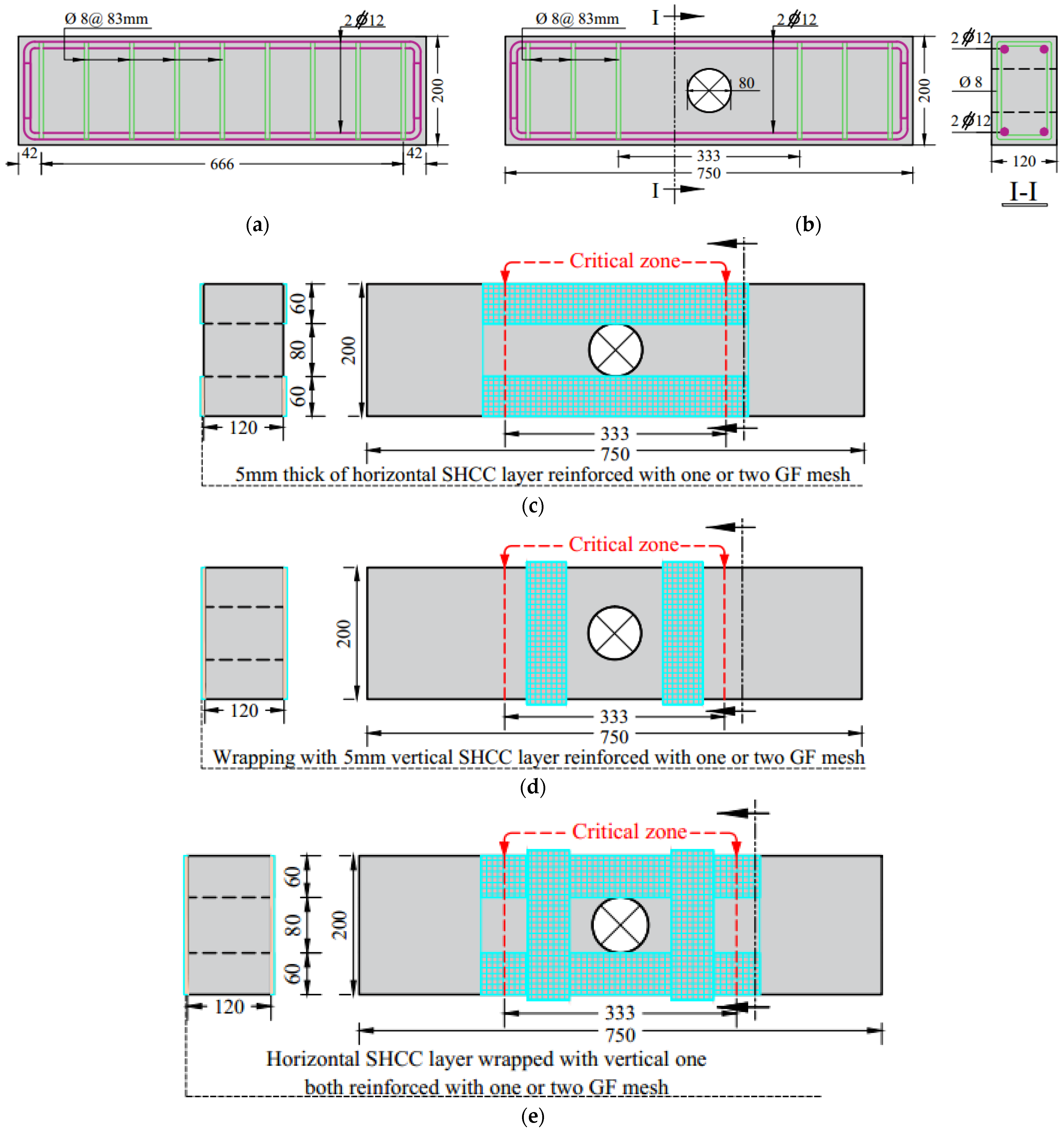
A total of eight full-scale RC beams, each measuring 120 mm × 200 mm in cross-section and 750 mm in length, were subjected to testing. As illustrated in Figure 1, every specimen incorporated two 12 mm-diameter steel bars placed in both the tension and compression zones. The control beam (B0), shown in Figure 1a, was equipped with 8 mm closed stirrups spaced at 83 mm intervals. Meanwhile, Figure 1b presents the intentionally weakened beam (B0-Df), which included an 80 mm diameter circular opening centered in the torsion-critical region. All beams shared the same dimensions, reinforcement detailing, and opening geometry, with variation introduced only through the applied retrofitting systems, which involved SHCC strips reinforced with glass fiber mesh.

Figure 1.
Geometric and reinforcement data: (a) master non-defected beam, (b) master defected beam, (c) horizontal strengthening regime, (d) vertical strengthening regime, and (e) horizontal strengthening confined with vertical strengthening wrapping.
To assess the impact of various strengthening strategies, the beam specimens were categorized into four distinct groups. As summarized in Table 1, each group consisted of beams with consistent design parameters, altering only one factor to isolate its effect on torsional behavior. G1 served as the baseline group, comprising two unstrengthened beams: one solid beam (B0) without an opening, and another defected beam (B0-Df) featuring a centrally located circular opening.

Table 1.
Test program.
G2 investigated the influence of horizontally applied SHCC strips on the torsional response of strengthened beams. Two beams—H-1 and H-2—were retrofitted with SHCC strips symmetrically placed on both sides of each beam. On each side, two horizontally aligned SHCC strips were positioned near the web opening, maintaining a vertical offset of 40 mm from its center. Each strip measured 400 mm in length, 60 mm in width, and 5 mm in thickness. In beam H-1, the SHCC strips were reinforced with a single layer of GF mesh, whereas beam H-2 incorporated two layers of GF mesh (Figure 1c).
Following the investigation of horizontally applied SHCC strips, G3 evaluated the effect of vertical SHCC strips on the torsional performance of strengthened beams. Two beams, V-1 and V-2, were retrofitted with vertical SHCC strips placed adjacent to the web opening, with a horizontal offset of 70 mm from its center. Each strip, measuring 60 mm in width and 5 mm in thickness, was fully wrapped around the beam’s cross-section. In beam V-1, the strips were reinforced with a single layer of GF mesh, while V-2 incorporated two GF mesh layers (Figure 1d).
Lastly, G4 explored the combined effect of horizontal and vertical SHCC strengthening on the torsional performance of strengthened beams. This group included two beams—Comb-1 and Comb-2—each retrofitted with horizontal SHCC strips confined by vertical wrapping. In Comb-1, the SHCC strips were reinforced with a single layer of GF mesh, while Comb-2 utilized two layers of GF mesh (Figure 1e).
2.2. Material Properties
2.2.1. Concrete Mixes
The experimental program involved two distinct concrete mixtures: normal concrete (NC) and strain-hardening cementitious composite (SHCC). The NC mixture had a water-to-binder ratio (w/b) of 0.42, as shown in Table 2. Furthermore, the SHCC mix was designed to achieve strain-hardening behavior and high tensile ductility. It had a water-to-binder ratio of 0.23. The mix also incorporated 2% polypropylene (PP) fibers and a high-range water reducer to improve workability.
Table 2.
Mix proportion of concrete.
The concrete’s compressive strength was evaluated using standard cylinder tests. To maintain uniformity in material properties, cylindrical specimens were cast at the same time as the beams and cured under identical environmental conditions. Each specimen had a diameter of 150 mm and a height of 300 mm, conforming to standard test specifications. Following the curing process, compression tests were performed on three samples, and their individual results were averaged to determine the final compressive strength (fc), as detailed in Table 2. For NC, the average compressive strength was 32 MPa, while SHCC achieved 64 MPa. To evaluate tensile properties, NC and SHCC were subjected to uniaxial tension tests using dog bone-shaped specimens. The measured tensile strengths were 2.56 MPa for NC and 5.31 MPa for SHCC.
2.2.2. Reinforcing Rebar and Glass Fiber Mesh
In this study, 8 mm bars served as stirrups, while the 12 mm bars were used for longitudinal reinforcement. Additionally, glass fiber (GF) mesh was embedded within the SHCC layer to enhance its structural integrity. A detailed assessment of the mechanical performance of the steel reinforcements was carried out through tensile testing, following the guidelines of ECP [36]. Based on testing, the D8 bars recorded yield and ultimate strengths of 291 MPa and 413 MPa, while D12 bars reached 362 MPa and 534 MPa. The GF mesh demonstrated a fracture value of 1544 MPa, as shown in Table 3.
Table 3.
Steel and glass fiber material properties.
2.2.3. ADDIBOND 65
Diluted ADDIBOND 65, a polymer-based bonding agent produced by Chemicals for Modern Building International (CMB) [37], was used as a binder to ensure effective adhesion between the existing concrete surface and the newly applied ferrocement layer. This material enhances the bond strength and compatibility between old and new construction layers.
2.3. Casting and Strengthening Procedures
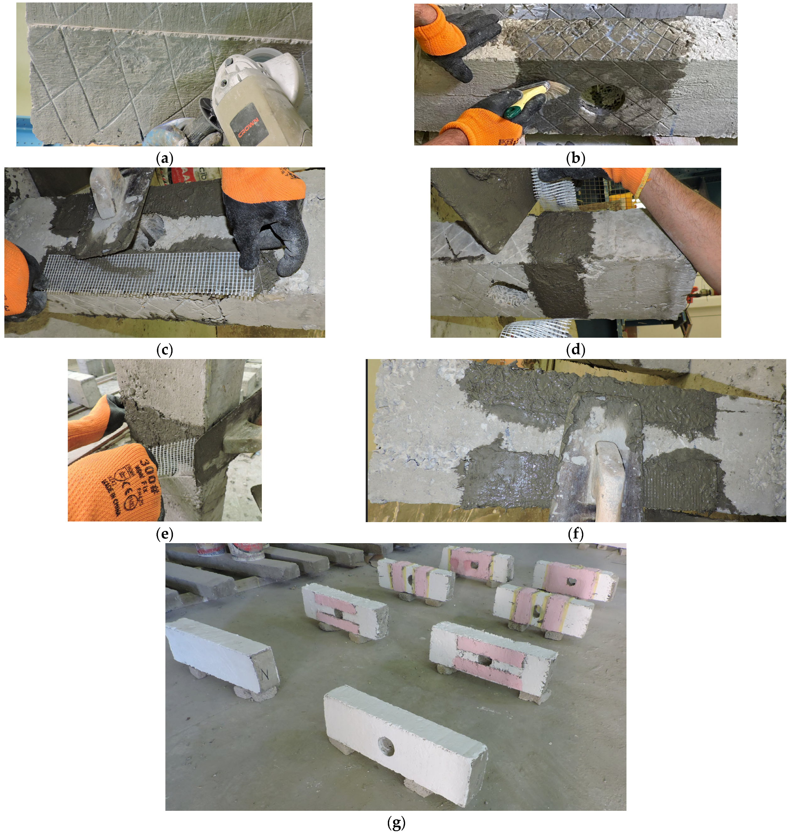
Eight RC beams were cast using appropriate formwork and reinforcement with a conventional concrete mix. After a 28-day curing period, circular openings with an 80 mm diameter were precisely cut in the torsion zone using a mechanical machine. Two beams were left without any strengthening as control samples, while the remaining six were reinforced around the openings in the middle zone using different strengthening techniques, as illustrated in Figure 2. The strengthening procedure involved a sequence of well-defined steps aimed at improving the torsional resistance of the RC beams. Initially, the concrete surface in the central zone (333 mm × 200 mm) of each beam was roughened to enhance shear friction and promote a strong mechanical bond with the SHCC overlay (Figure 2a). Following surface preparation, a bonding agent (ADDIBOND 65) was applied to the treated area to ensure adequate adhesion and prevent delamination between the existing substrate and the new SHCC layer under loading conditions (Figure 2b). The various strengthening configurations, as outlined in Table 1, with orientations of horizontal (Figure 2c), vertical (Figure 2d), and combined (Figure 2e) SHCC strips, were then applied. Subsequently, a rendering layer was applied to smooth and protect the strengthened surface (Figure 2f). A comprehensive view of all the tested beams after the strengthening process is presented in Figure 2g.

Figure 2.
Prefabrication of the strengthening process: (a) beams roughening, (b) bonding agent application, (c) reinforcing the SHCC layer with GF layer horizontally, (d) adding the GF sheet vertically on the SHCC layer, (e) wrapping process, (f) rendering of the strengthening layer, and (g) view of the beams ready for testing.
2.4. Test Setup and Loading Arrangement
The test setup was designed to evaluate the torsional performance of RC beams (Figure 3). A 2500 kN-capacity testing machine was used to apply the load. The beams, painted white for better crack detection, were mounted in the machine, and a box steel beam was utilized to distribute the load. The box beam was attached to two 500 mm torsional steel arms through hinged joints, ensuring the flexibility needed for accurate torsional application. These arms were securely fixed at the beam ends, supported by pinned supports, allowing free rotation while preventing other types of movement.
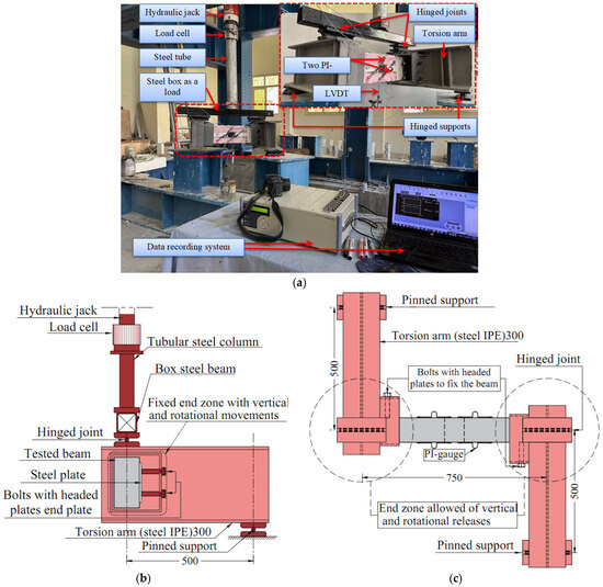
Figure 3.
Test details: (a) view of the experiment, (b) side view of the test, (c) plan view of the test.
To maintain pure torsion and avoid bending stresses, the loading lever arm was oriented perpendicular to the beam’s longitudinal axis. A point load was applied to the upper surface of the box steel beam, and midspan displacement was measured using a linear variable displacement transducer (LVDT). Loading was incrementally increased at a rate of 0.1 mm/min until failure. Deflections were monitored with a data logger, and cracks were documented visually. Upon failure, the LVDT was promptly disconnected for analysis.
3. Results of Tests and Discussion
This section details the tested beams’ results, focusing on crack and failure patterns, ultimate load, load–displacement behavior, elastic stiffness, and energy absorption. Table 4 summarizes key parameters, including ultimate load (Pu), ultimate displacement (∆u), absorbed energy (E) from the load–displacement curve, and initial stiffness (K) from the elastic slope.
Table 4.
Test results.
3.1. Failure Patterns
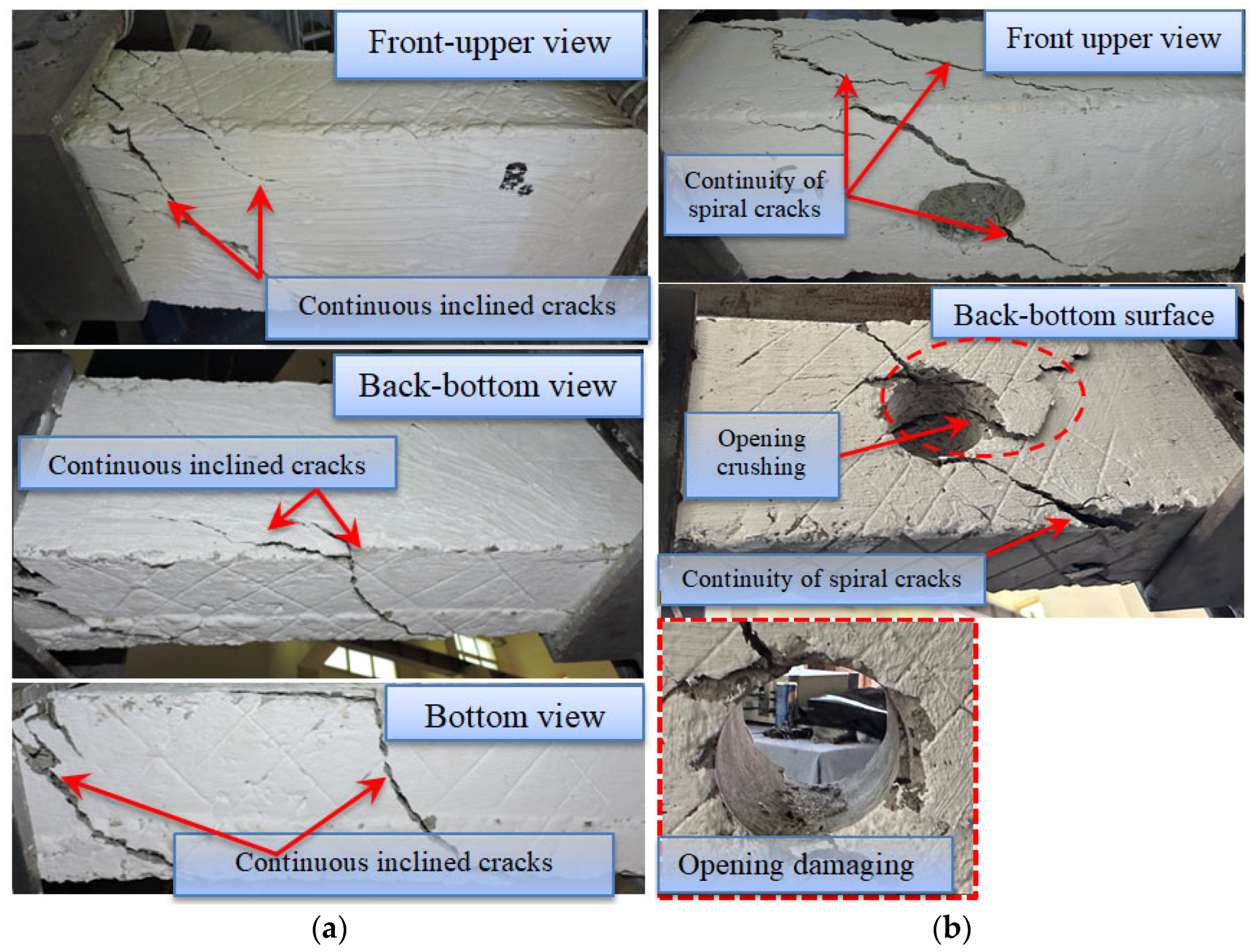
During the loading process, cracks and failure modes were systematically recorded at each load increment until the beams reached failure. The crack patterns and modes for G1 to G4 are shown in Figure 4, Figure 5, Figure 6 and Figure 7. All beams exhibited conventional torsional failure, with cracks forming at approximately 45° angles along the beam’s surface. These cracks typically originated near the openings, where the torsional stress distribution was interrupted. The first crack generally appeared at the opening’s corner and spread in a diagonal direction. As the torsional load increased, the cracks enlarged and followed a helical trajectory, highlighting the dominant shear stresses within the beam. Further loading caused these diagonal cracks to intersect, forming a distinct torsional failure plane. The ultimate failure occurred due to concrete crushing near the opening and yielding of both transverse and longitudinal reinforcement. Depending on the reinforcement ratio and concrete strength, failure was either sudden and brittle or more gradual.
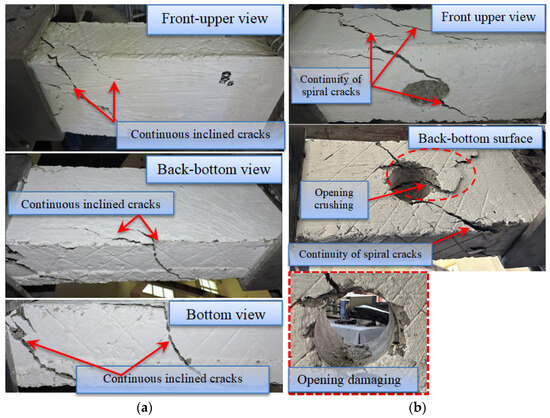
Figure 4.
Cracks and failure modes for master beams: (a) beam B0 and (b) beam B0-Df.
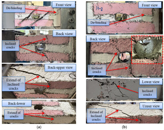
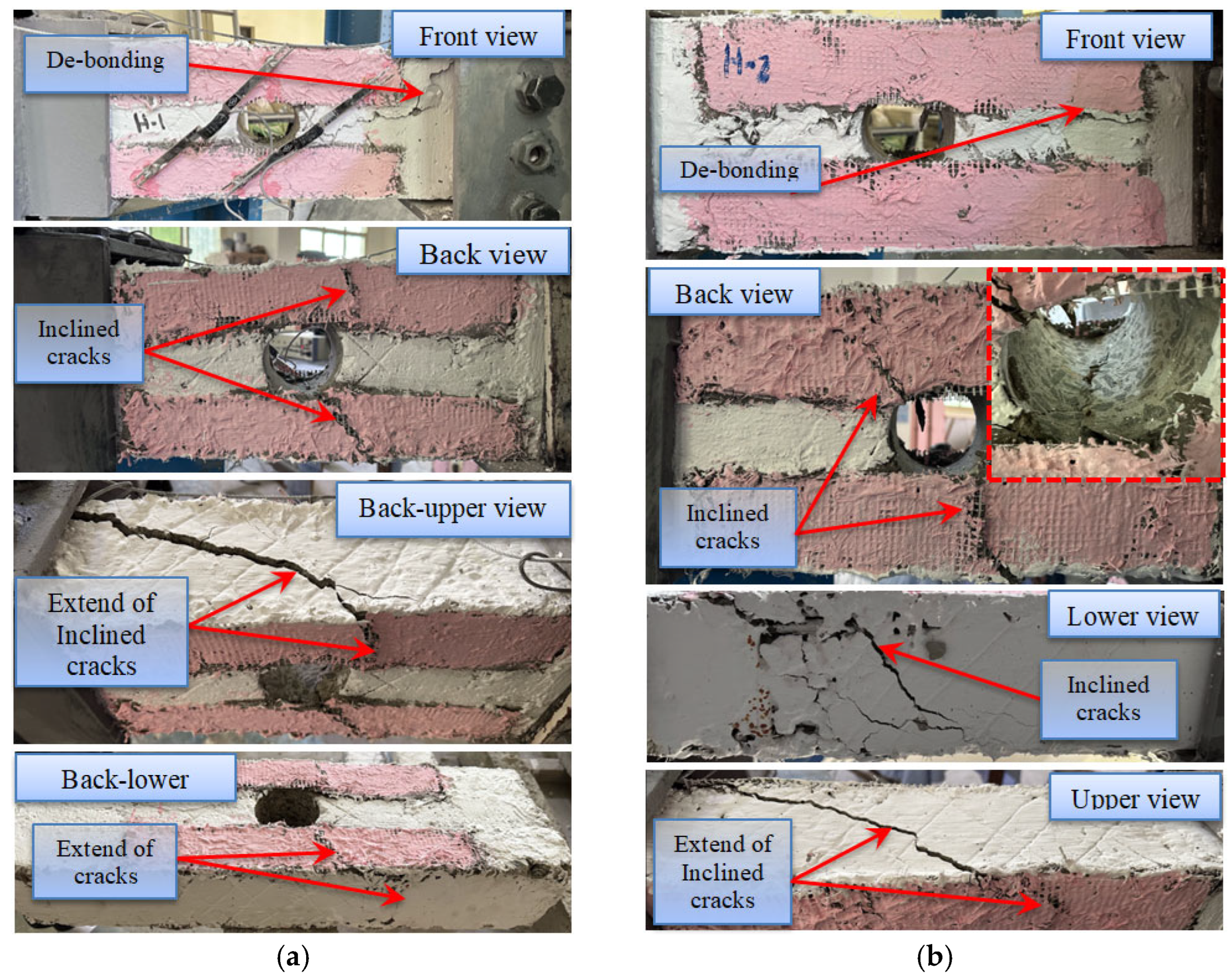
Figure 5.
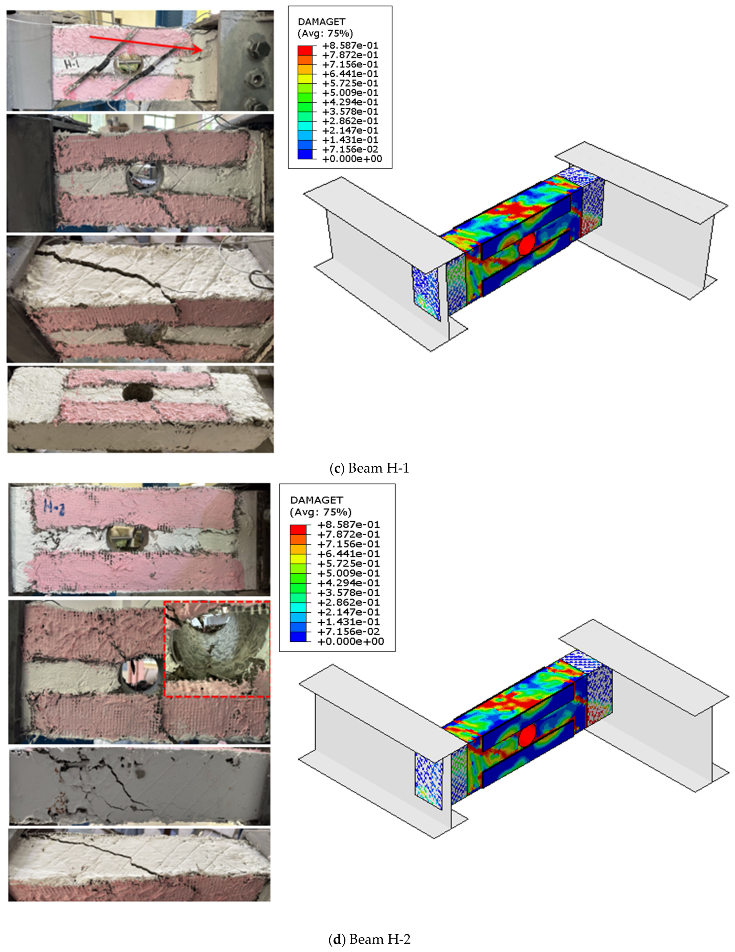
Cracks and failure modes: (a) beam H-1 and (b) beam H-2.

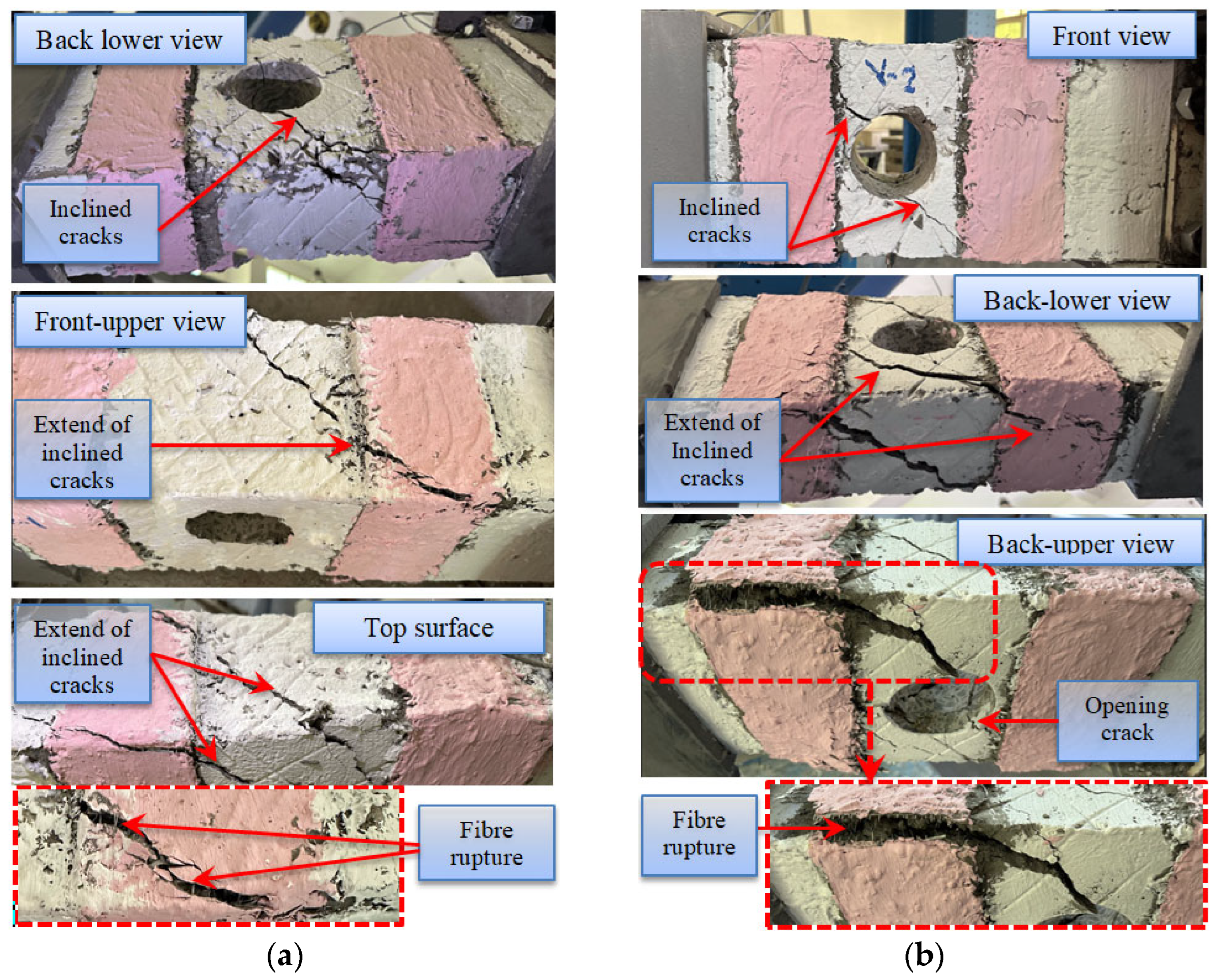
Figure 6.
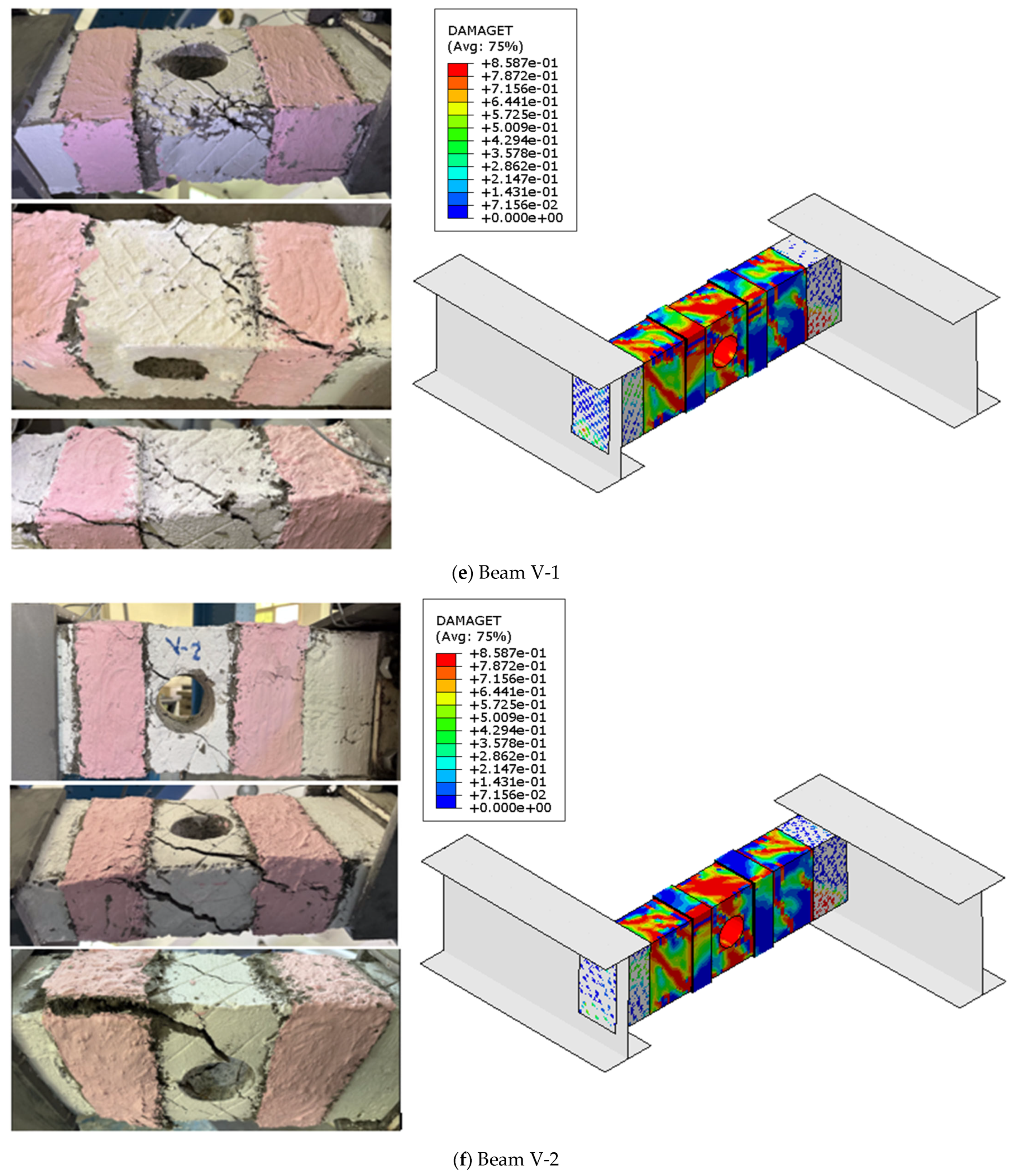
Cracks and failure modes: (a) beam V-1 and (b) beam V-2.

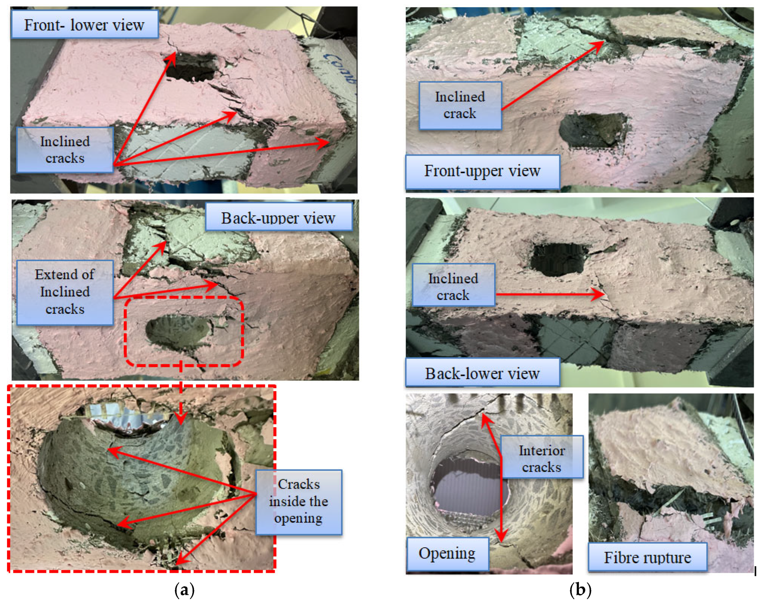
Figure 7.
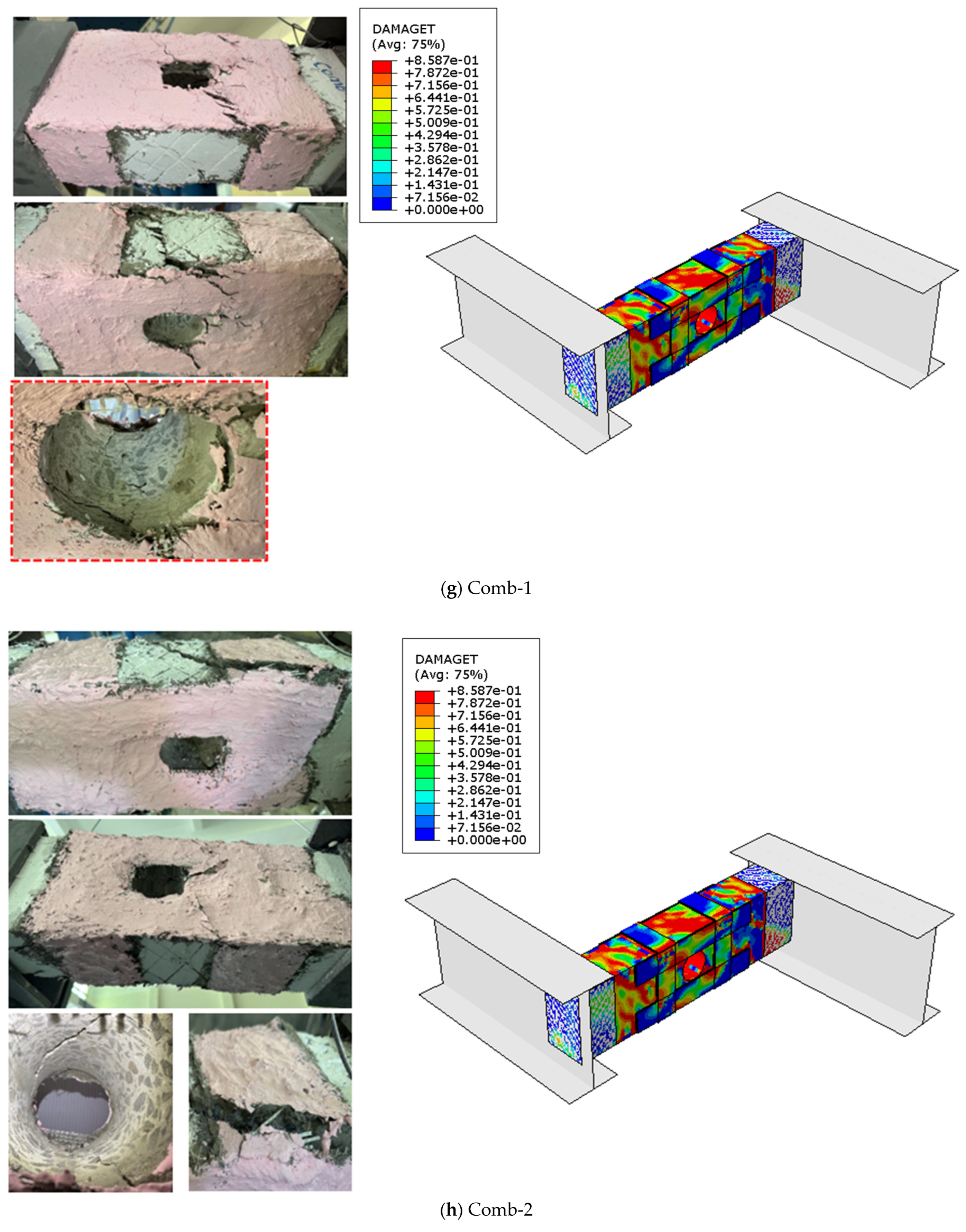
Cracks and failure modes: (a) beam comb-1 and (b) beam comb-2.
Circular openings compromised the torsional resistance by reducing the effective concrete area and interrupting the load transfer path. This disruption accelerated crack propagation and decreased the torsional capacity. These results are consistent with findings from previous studies [38,39,40].
In G1, the beam B0-Df, which included a central circular opening, exhibited the most noticeable failure behavior. As seen in Figure 4b, a significant diagonal crack developed near the opening and spread toward the edges, accompanied by several inclined cracks. The beam failed at a load of 14.97 kN, and the cracks formed at angles of 40° to 50° relative to the beam’s length. The main crack extended through the opening, resulting in localized crushing and eventual failure. On the other hand, the control beam B0, which did not have an opening, failed at 21.14 kN, with a typical torsional shear failure characterized by a diagonal crack at a 45° angle (Figure 4a).
In G2 (Figure 5), the effect of horizontal SHCC strips on the torsional performance of strengthened beams with openings was evaluated. All beams in this group exhibited typical torsional shear failure. The SHCC strips showed signs of de-bonding, and inclined cracks formed, extending through the beam and passing through the opening. The progression of these cracks was visible as they spread across the beam, with the extent of the cracks clearly evident in the lower portion. Although the failure pattern was similar in both beams, beam H-2, which had horizontal SHCC strips reinforced with two layers of GF mesh, exhibited a delay in the appearance of the initial cracks.
Likewise, the beams in G3—which investigated the effect of vertical SHCC strips on the torsional behavior of strengthened beams with openings—exhibited a failure pattern similar to that of G2. However, they demonstrated better resistance to crack propagation and delayed failure. The two beams (V-1 and V-2) failed at the ultimate load due to concrete deterioration around the opening, accompanied by the development of continuous spiral cracks along the sides of the beam and rupture of the GF mesh, as shown in Figure 6.
On the other hand, the combination of horizontal and vertical SHCC strips in G4 beams significantly delayed the initiation of cracks compared to the other tested groups (Figure 7). This enhancement in performance can be attributed to the complementary roles of the two strip orientations: the horizontal SHCC strips effectively distributed torsional stresses along the beam’s length, while the vertical strips provided additional resistance to shear and torsional forces. Together, they worked synergistically to hinder crack propagation, thereby enhancing the beam’s overall structural integrity and torsional performance.
3.2. Load—Displacement Curves
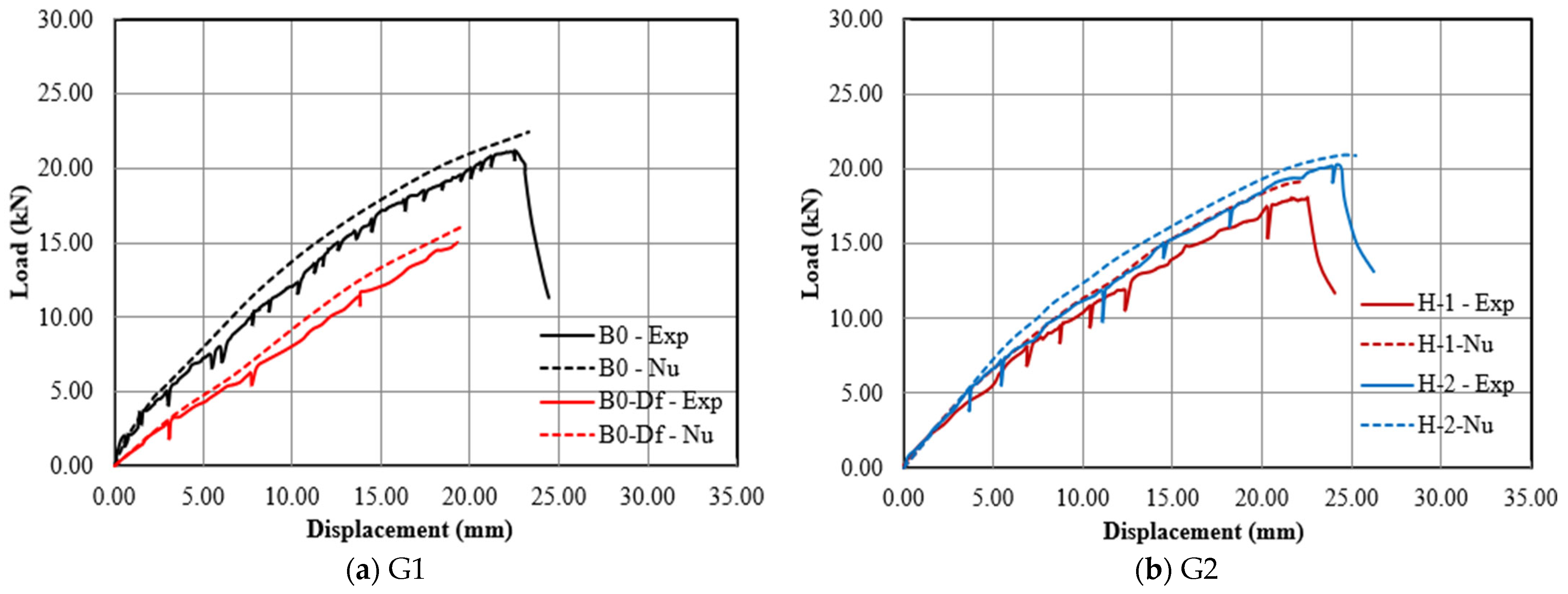
Figure 8 presents the load–displacement (P–Δ) behavior for all tested beams. For comparison purposes, the control beams are included. The response curves exhibit three distinct phases. Figure 8a shows the P–Δ relationship of the baseline beams B0 and B0-Df during the loading stages, revealing a significant improvement in the P–Δ relationship of beam B0 compared to beam B0-Df. Beam B0 exhibited the highest ultimate load capacity and elastic stiffness, as indicated by the steeper slope of the load–displacement curve, along with the greatest ultimate displacement (22.52 mm). These results highlight the substantial impact of the circular opening in the defective zone, which caused a notable reduction in load–deflection behavior, including a 14.43% decline in the ultimate displacement (∆u), thereby diminishing the beam’s torsional performance.
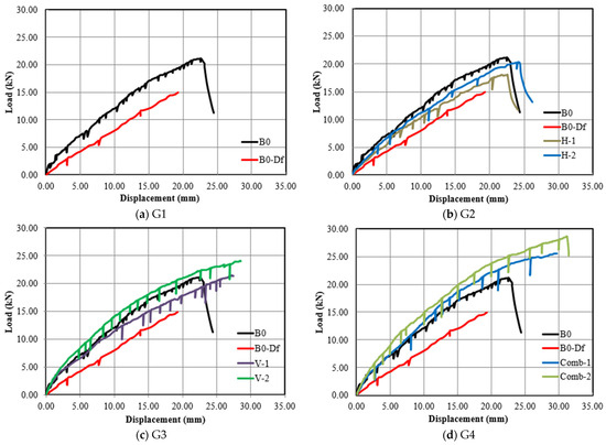
Figure 8.
Load–vertical displacement response for all groups.
The P–Δ relationship in Figure 8b illustrates the effect of horizontal SHCC strips reinforced with single and double GF mesh layers on the torsional behavior of the strengthened beams with openings. Notably, beam H-2, which incorporated horizontal SHCC strips with double GF mesh layers, exhibited the highest stiffness and strength, as indicated by its steepest P–Δ slope and maximum ultimate load. Its ultimate displacement (∆u) increased by 26.40% compared to the defective beam B0-Df (with opening), reflecting a significant improvement in deformation capacity. Similarly, beam H-1, strengthened with horizontal SHCC strips and a single GF mesh layer, showed a 17.12% increase in ∆u over B0-Df. These findings confirm the effectiveness of horizontal SHCC strips in enhancing torsional performance and energy absorption. However, despite these gains, both beams still underperform relative to the solid control beam B0 (without opening).
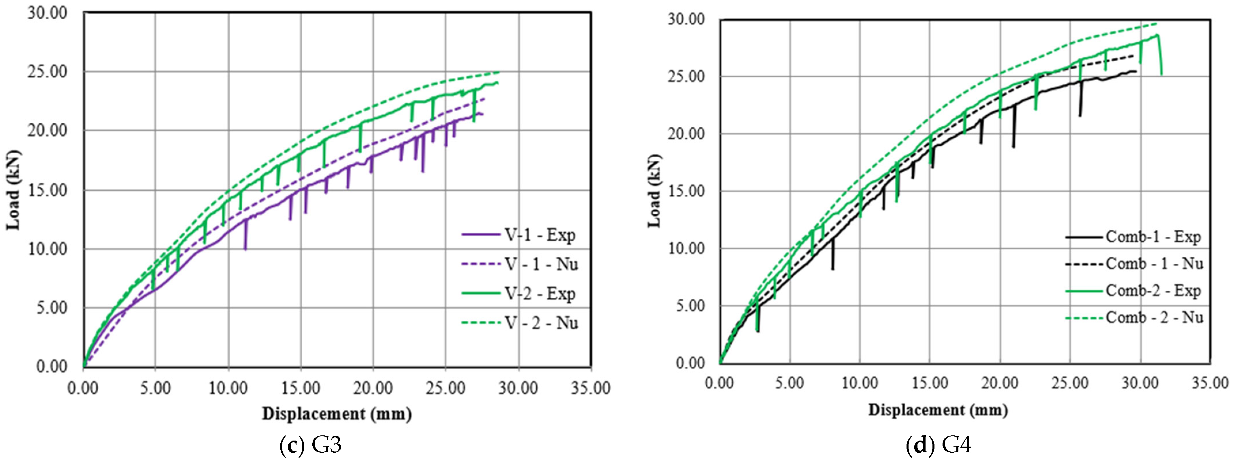
Likewise, the beams in G3—which examined the effect of vertical SHCC strips on the torsional behavior of the strengthened beams with openings—showed a notable enhancement in the P–Δ relationship compared to beam B0-Df (Figure 8c), similar to the trend observed in G2. Beam V-2, incorporating vertical SHCC strips with double GF mesh layers, demonstrated the highest stiffness and strength, as reflected by its steepest P–Δ slope and maximum ultimate load. Its ultimate displacement (∆u) increased by 48% relative to B0-Df. Similarly, beam V-1, with a single GF mesh layer, exhibited a 42.60% increase in ∆u. Unlike the beams in G2, beam V-2 outperformed the solid control beam B0, while beam V-1 remained inferior in performance.
On the other hand, the beams in G4 (Figure 8d)—which examined the combined effect of horizontal and vertical SHCC strips on the torsional behavior of strengthened beams with openings—demonstrated superior P–Δ performance compared to those in the other groups. Notably, beam Comb-2 exhibited the best overall behavior among all tested specimens, achieving the highest stiffness and strength, as reflected by its steepest P–Δ slope, maximum ultimate load, and greatest ultimate displacement (∆u). It showed a 61.70% increase in ∆u compared to the defective beam B0-Df and a 38.40% increase relative to the solid control beam B0. Similarly, beam Comb-1 achieved a 54.17% improvement in ∆u over B0-Df and a 32% increase compared to B0. These results confirm that incorporating double layers of GF mesh significantly enhances the P–Δ response, consistent with observations from G2 and G3. Overall, the findings highlight the potential of this strengthening technique to match or even surpass the performance of solid beams.
3.3. Ultimate Strength
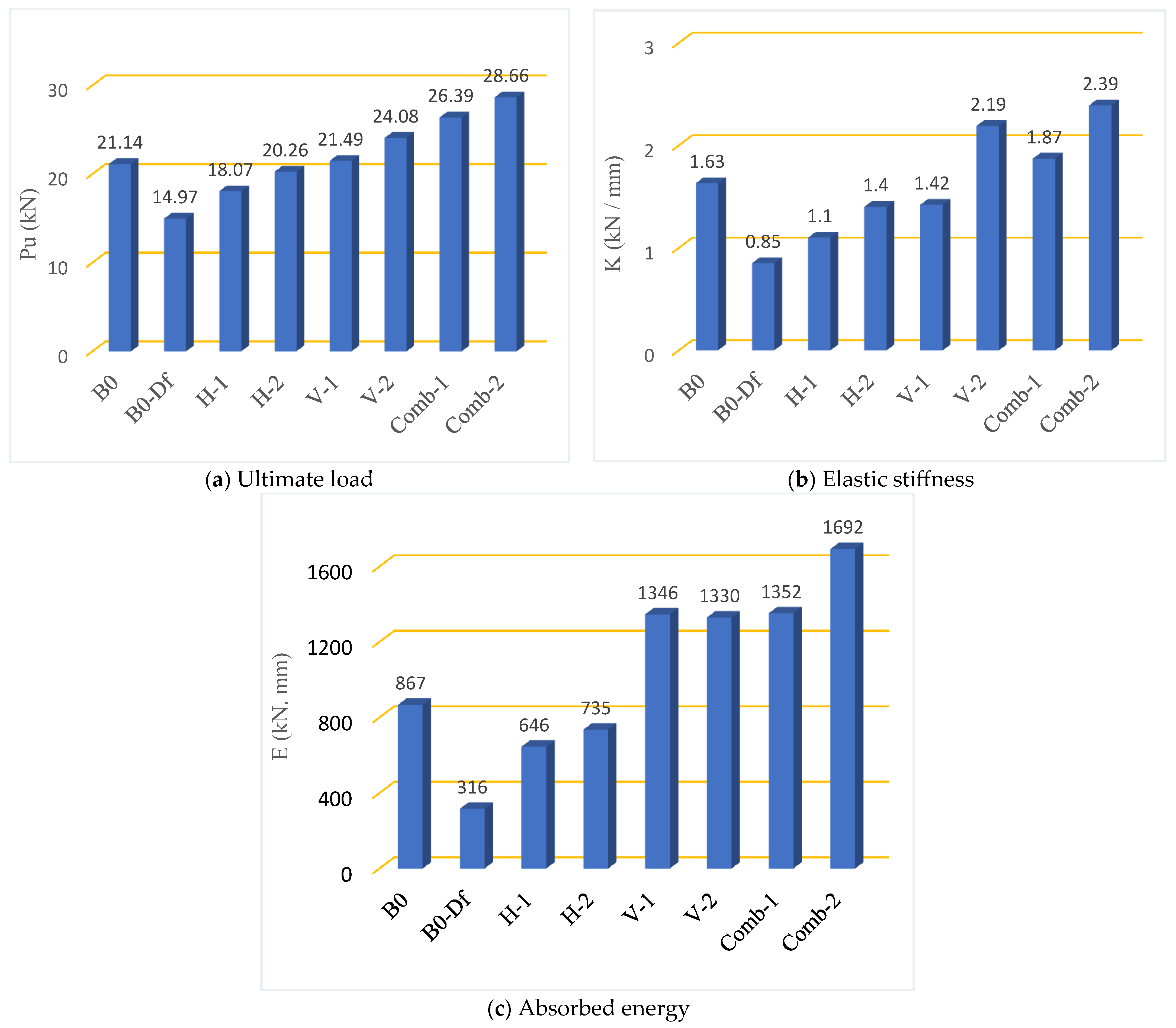
Table 4 displays the ultimate load (Pu) recorded for each tested beam, highlighting the influence of various strengthening methods on structural performance. Overall, using SHCC strips as a strengthening technique enhances the ultimate torsion capacity of strengthened beams, as shown in Figure 9a.
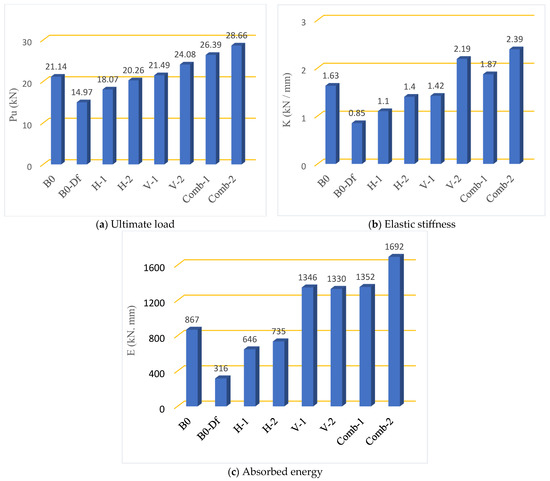
Figure 9.
Ultimate load, elastic stiffness, and absorbed energy of the tested beams.
A closer analysis of G1 beams, the baseline group, reveals ultimate loads of 21.14 kN for beam B0 and 14.97 kN for beam B0-Df, as shown in Table 4. These findings indicate that the presence of a circular opening in the central (defective) zone reduces the ultimate torsion capacity by 29%. This reduction is primarily due to the opening weakening the beam’s cross-sectional area, thereby reducing its ability to resist torsional stresses. Moreover, the disruption of concrete continuity and the loss of confinement around the opening create stress concentrations, accelerating crack initiation and propagation under torsional loading. These combined effects weaken the beam’s structural integrity, resulting in a lower ultimate torsion capacity. This aligns with the findings reported in the research [38,41].
G2 beams were tested to evaluate the impact of horizontal SHCC strips reinforced with single and double layers of GF mesh on torsional performance. As shown in Table 4, the ultimate loads (Pu) for beams H-1 and H-2 were 18.07 kN and 20.26 kN, representing increases of 21% and 35%, respectively, compared to the defective beam B0-Df, and reductions of 15% and 4% relative to the control beam B0. These improvements are attributed to the enhanced confinement and crack-bridging capability provided by the SHCC strips and GF mesh. The superior performance of H-2 over H-1 indicates that using a double-layer GF mesh offers more effective reinforcement, promoting better stress distribution and increased torsional resistance.
G3 examined the impact of vertical SHCC strips on the torsional behavior of beams with openings. The ultimate loads (Pu) for beams V-1 and V-2 reached 21.49 kN and 24.08 kN, marking increases of 44% and 61% over the defective beam B0-Df, and enhancements of 2% and 14% compared to the control beam B0. This superior performance suggests that vertical SHCC strips are more effective than horizontal ones in resisting torsional stresses, likely due to their alignment with principal tensile cracks and enhanced crack-bridging capability under torsion.
On the other hand, the beams in G4 (Table 4)—which investigated the combined effect of horizontal and vertical SHCC strips on the torsional behavior of strengthened beams with openings—demonstrated superior load capacity compared to all other groups. Notably, beam Comb-2 recorded the highest Pu among all tested specimens, showing a 91% increase relative to the defective beam B0-Df and a 36% increase compared to the solid control beam B0. Beam Comb-1 exhibited a 76% improvement over B0-Df and a 25% increase relative to B0. These findings confirm that the combined use of horizontal and vertical SHCC strips, particularly with double layers of GF mesh, significantly enhances ultimate torsional capacity.
The superior performance of G4 beams can be attributed to the synergistic effect of both horizontal and vertical SHCC strips. The integration of these strips provides multi-directional reinforcement, significantly enhancing the beams’ ability to resist torsional forces. The use of double layers of GF mesh likely plays a key role in improving the torsional capacity. This additional reinforcement improves the crack-bridging ability of the SHCC strips and contributes to better load distribution and stress transfer, leading to enhanced structural strength. The SHCC strips provide confinement to the concrete, preventing excessive cracking and increasing the beam’s resistance to shear and torsional stresses. This is particularly beneficial in beams with openings, where the structural integrity can otherwise be compromised.
3.4. Elastic Stiffness and Absorbed Energy
Table 4 shows the computed values of elastic stiffness and energy absorption for the tested beams. Elastic stiffness (K) quantifies the initial resistance to deformation, while absorbed energy (E) evaluates the beam’s ability to withstand and dissipate energy under applied loads. Overall, using SHCC strips reinforced with GF mesh as a strengthening technique enhances the elastic stiffness and energy absorption in the strengthened beam, as shown in Figure 9b,c.
In G1, calculations indicated that the presence of a circular opening in the central (defective) zone (beam B0-Df) reduced the elastic stiffness and energy absorption capacity by 48% and 64%, respectively, compared to beam B0 (without an opening). The observed reductions in elastic stiffness and energy absorption capacity in beam B0-Df, which features a central circular opening, can be attributed to the stress concentrations and interruptions in the load transfer path introduced by such openings [42].
In G2, beam H-2 exhibited the most notable enhancement in elastic stiffness, showing a 65% increase compared to the defective beam B0-Df and a 14% reduction relative to the control beam B0, as presented in Table 4. Beam H-1 followed with a 30% improvement over B0-Df, and a 32% decrease compared to B0. Regarding energy absorption, H-2 also showed the highest gain, achieving a 133% increase over B0-Df and a 15% reduction relative to B0. Similarly, H-1 recorded a 104% improvement over B0-Df, and a 26% decrease compared to B0.
On the other hand, in G3, beam V-2 exhibited the most significant improvement in elastic stiffness, showing a 158% increase compared to the defective beam B0-Df and a 35% enhancement relative to the control beam B0, as presented in Table 4. Beam V-1 followed, with a 67% improvement over B0-Df and a 13% reduction compared to B0. In terms of energy absorption, V-2 achieved a 321% increase over B0-Df and a 53% improvement relative to B0, while V-1 recorded a 326% increase over B0-Df, and a 55% improvement compared to B0.
Furthermore, the combination of horizontal and vertical SHCC strips in G4 resulted in a significant improvement in both elastic stiffness and energy absorption compared to the beams in G2 and G3, which had the same number of GF mesh layers, as shown in Table 4. Notably, beam Comb-2 recorded the highest values of elastic stiffness (K) and energy absorption (E) among all tested specimens, with a 181% increase in K compared to B0-Df and a 46% increase relative to B0. In terms of energy absorption, Comb-2 showed a 436% increase over B0-Df, and a 95% improvement compared to B0. Beam Comb-1 followed, exhibiting a 120% increase in elastic stiffness (K) compared to B0-Df and a 15% improvement over B0. In terms of energy absorption (E), Comb-1 showed a 328% increase relative to B0-Df and a 56% enhancement compared to B0.
4. Numerical Investigation
4.1. Model Setup and Interactions
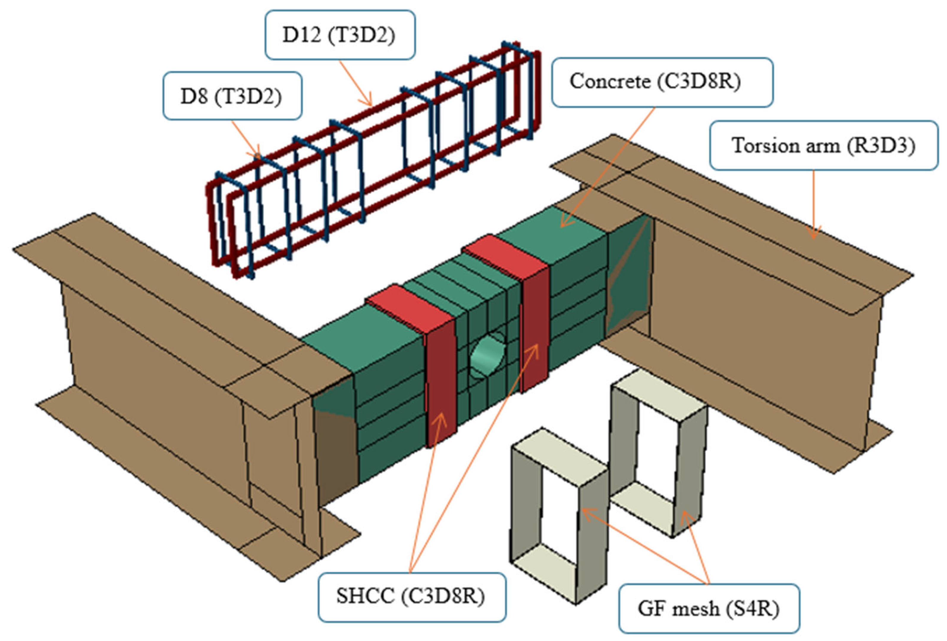
ABAQUS software 14 was used to develop finite element models of the tested beams. Figure 10 illustrates the finite element model developed for beam V-1. The RC and SHCC were modeled using C3D8R elements—eight-node linear brick elements with reduced integration and hourglass control—ensuring accurate representation of complex geometries and material behavior. The torsion arm was modeled using R3D3 elements, which are three-node rigid body elements commonly used for non-deformable components. Additionally, the reinforcement bars and stirrups were represented using T3D2 elements, a two-node linear truss type ideal for capturing axial load resistance. The GF mesh was modeled using S4R elements—four-node doubly curved shell elements with reduced integration.

Figure 10.
Element types of beam V-1.
To define the boundary conditions, hinged supports were implemented at both beam ends, ensuring stability while allowing rotational movement. Displacement-controlled loading was introduced at a designated reference point to facilitate the analysis of all tested beams (Figure 11). This setup, combined with the refined element modeling, effectively captures the structural behavior of the beam under applied loads, enhancing the accuracy of the simulation.
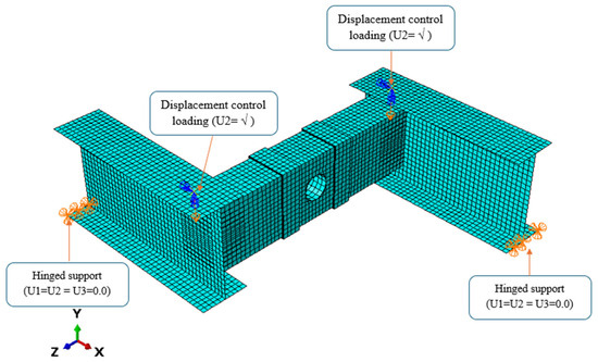
Figure 11.
Typical meshing, boundary conditions, and loading of the tested beams.
Furthermore, in ABAQUS, the embedded region technique was used to simulate the interaction between the reinforcing steel and concrete, as well as between the GF mesh and SHCC strips [6,7,34,43,44,45]. This constraint ensures that the nodes of the reinforcement rebars and the surrounding concrete are fully coupled, sharing the same degrees of freedom. The interaction between the SHCC strips and the substrate RC beams for all tested specimens was modeled using a surface-to-surface contact algorithm. A hard contact condition was applied to simulate the normal interaction and prevent interpenetration. For the tangential behavior, a friction coefficient of 0.44 was adopted, consistent with earlier studies [8,34,46,47].
A sensitivity analysis was conducted to determine the optimal mesh size for the finite element model, balancing accuracy and computational efficiency. Mesh sizes from 5 mm to 30 mm were tested against the experimental data. The results showed that a 15 mm mesh accurately captured the beam’s behavior while reducing computational costs, offering a reliable and efficient modeling solution (Figure 11).
4.2. Materials Laws
To accurately capture the complex stress responses of NC and SHCC, the study employed the concrete damage plasticity (CDP) model. This versatile model can effectively replicate the compressive and tensile behavior of various concrete types [6,7,34,44,45,48,49,50,51,52]. For NC, a well-established stress–strain relationship developed by Carreira and Chu [53] (Equations (1)–(3)) was incorporated into the simulations. This proven approach ensures accurate predictions of NC’s behavior under stress. For SHCC, stress–strain correlations for compressions were established based on the work of Zhou et al. [54] (Equations (4) and (5)). To ensure the simulations accurately capture the real behavior of the materials, a two-stage bilinear stress–strain relationship was meticulously calibrated for the uniaxial tensile performance using experimental data.
where fc and εc represent the stress and strain of the concrete material, respectively. The variables f′c and εco correspond to the peaked compressive stress and its associated strain, respectively. Furthermore, the β factor can be determined using Equation (3), which is derived based on the stress–strain depiction.
where E0 and εcp represent the SHCC modulus of elasticity and the strain at the ultimate stage, respectively. ftc and εtc denote the tensile strength beside the associated strain of SHCC at first crack. ftu and εtu refer to tensile strength beside strain at the ultimate region.
To ensure the CDP model accurately reflects the behavior of different concrete materials, a sensitivity analysis was conducted to fine-tune its key parameters. Based on this analysis, the angle of dilatation (ψ) for NC and SHCC was taken as 25 degrees, and 30 degrees, respectively. The default values suggested by ABAQUS were assigned to parameters namely eccentricity flow potential (e) and biaxial to uniaxial compressive strength ratio (fb0/fc0).
The tensile behavior of steel was idealized using a bilinear isotropic material model. The elastic portion was defined by Young’s modulus and Poisson’s ratio, while the plastic region was characterized by yield stress and ultimate tensile stress, as listed in Table 3.
4.3. FEM Verification
A comprehensive verification framework was established to assess the accuracy of the finite element models (FEMs) by comparing their outputs with experimental results. The comparisons of the load–displacement behavior shown in Figure 12 show that the FEMS simulations successfully replicated the specimens’ responses across all loading stages, demonstrating their reliability in capturing real-world structural behavior.
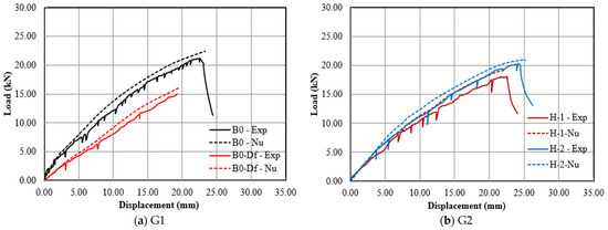
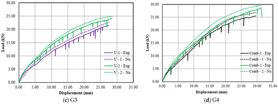
Figure 12.
A comparison of numerical versus experimental load–deflection relationships of the tested beams.
Quantitative validation, as shown in Table 5, reinforces the reliability of the models through detailed comparisons between predicted and experimental results. Key performance indicators, including the ultimate load capacity (Pu) and corresponding deflection (∆u), were analyzed. The FEMs demonstrated excellent predictive accuracy at the ultimate loading stage, with a mean FE/EXP load ratio of 0.956 and low variability (SD = 0.017). Similarly, the predicted displacement closely matched experimental observations, with a ratio of 1.054 and a standard deviation of 0.016.
Table 5.
A comparison of numerical versus experimental results.
The comparisons of the failure modes illustrated in Figure 13 confirm that the FEMs accurately capture the actual behavior observed in the experiments, including various failure modes and crack propagation patterns. This ability to replicate complex real-world phenomena strengthens the models’ credibility. Overall, the validation process provides compelling evidence of the FEMs’ high accuracy and reliability. This achievement paves the way for their confident application in future analyses and predictions of the structural behavior of similar specimens.
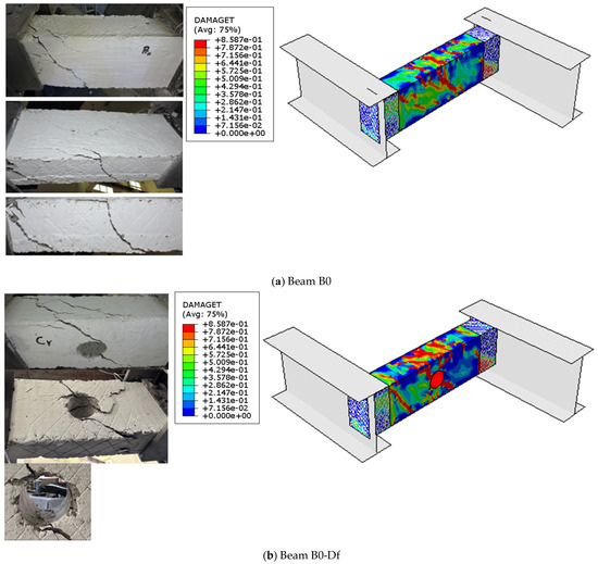
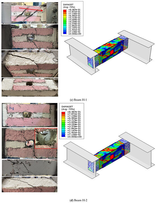


Figure 13.
Comparison of experimental and numerical failure patterns.
5. Parametric Study
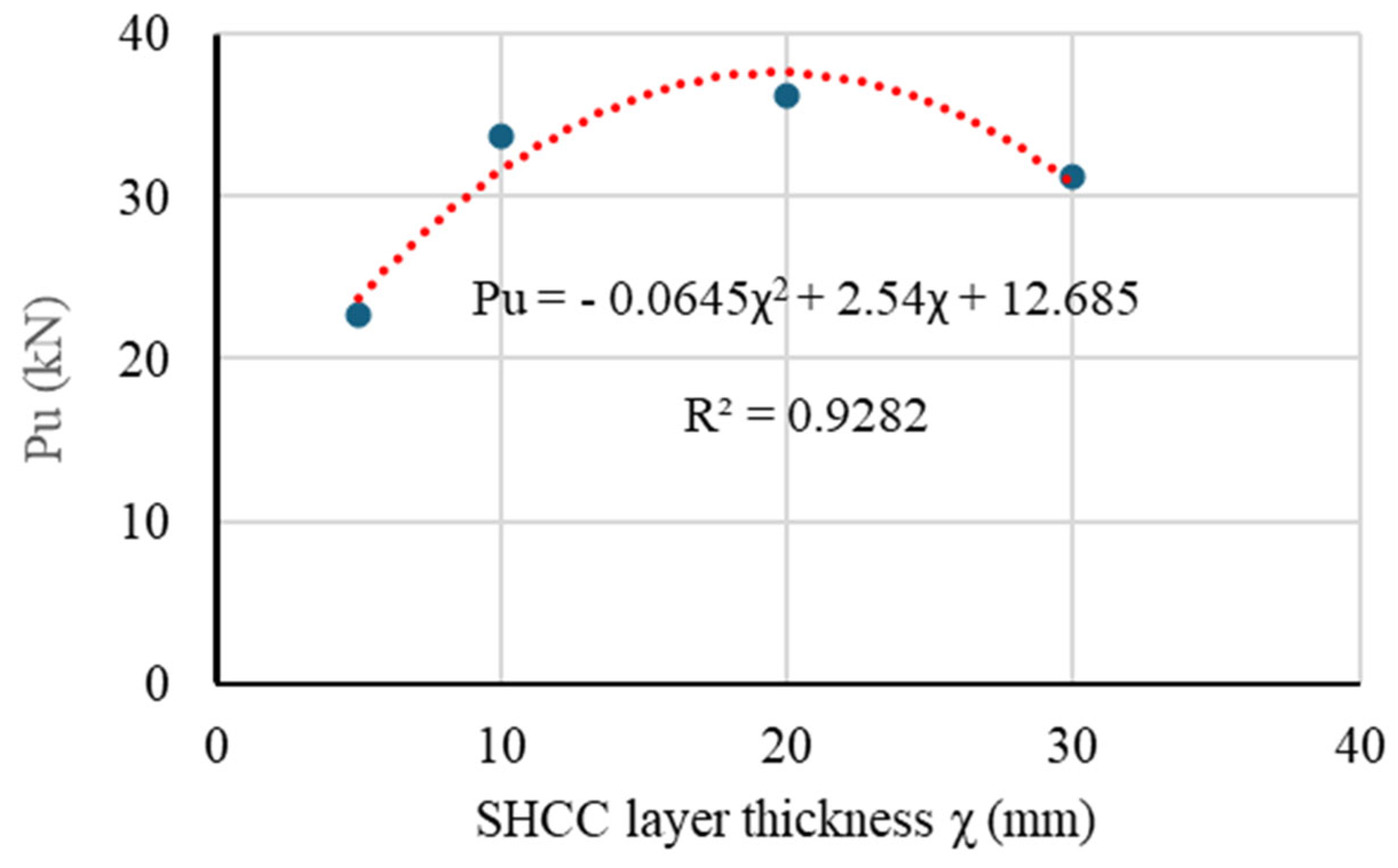
A parametric study using the validated numerical model was carried out to evaluate the influence of SHCC layer thickness (χ) on punching shear capacity. Beam V-1 was chosen for the parametric study, with fixed dimensions and reinforcement, while varying the SHCC layer thickness to assess its effect. The analysis examined strengthening with χ ranging from 5 mm to 30 mm. The results demonstrate a significant influence of the SHCC layer thickness (χ) on the punching shear performance of beam V-1 (Figure 14), revealing a clear trend of increasing punching capacity with larger χ values. Notably, increasing χ from 5 mm to 20 mm led to a 60% increase in the ultimate punching shear capacity. However, beyond χ = 20 mm, the ultimate load began to decline, indicating that 20 mm is the optimal thickness. The relationship between the ultimate punching shear capacity (Pu) and χ can be expressed by the following quadratic equation:

Figure 14.
Impact of SHCC layer thickness on the ultimate punching shear capacity.
6. Conclusions
This study investigated the effectiveness of strain-hardening cementitious composites (SHCC) reinforced with glass fiber (GF) mesh in enhancing the torsional behavior of reinforced concrete (RC) beams with circular openings. Eight specimens were tested to evaluate the effects of horizontal and vertical SHCC strips, reinforced with single and double GF mesh layers, as well as the combined application of horizontal and vertical SHCC strips with similar reinforcement configurations. Experimental and numerical analyses yielded the following key findings:
- Stress concentrations around the opening accelerated crack propagation, leading to premature failure.
- Strengthened beams showed delayed crack initiation, reduced crack widths, and improved post-cracking ductility due to the strain-hardening properties of SHCC and the crack-bridging effect of GF mesh.
- The presence of a circular opening reduced the ultimate torsional capacity by 29%, elastic stiffness by 48%, and energy absorption by 64% compared to the solid beam.
- Horizontal SHCC strips improved torsional capacity by 21–35%, while vertical SHCC strips provided even greater enhancement (44–61%).
- The combined horizontal and vertical SHCC configuration demonstrated the best performance, increasing the ultimate load by 76–91% and energy absorption by 328–436% compared to the defective beam.
- Double-layer GF mesh reinforcement consistently outperformed single-layer reinforcement in all configurations, enhancing ductility and crack resistance.
- A parametric study revealed that an optimal SHCC thickness of 20 mm maximizes punching shear capacity, beyond which gains diminish.
This study confirms that retrofitting with SHCC and GF mesh is a highly effective method for restoring and enhancing the torsional capacity of RC beams with openings, offering a practical solution for structural rehabilitation in contemporary construction. For optimal torsional performance, the combined application of horizontal and vertical SHCC strips reinforced with double-layer GF mesh is recommended.
Author Contributions
Conceptualization, A.H.; methodology, A.H.; software, A.H. and S.A.Y.; validation, A.H. and S.A.Y.; formal analysis, A.H. and S.A.Y.; investigation, A.H., S.A.Y. and H.A.; data curation, A.H., M.A., S.A.Y., H.A. and A.A.A.; writing—original draft, A.H. and S.A.Y.; writing—review and editing, M.A., K.S., A.A.A.,V.I.P. and H.A.; visualization, M.A., A.A.A., K.S., H.A. and V.I.P.; project administration, A.H. and A.A.A. All authors have read and agreed to the published version of the manuscript.
Funding
The authors thank the support provided by the Ongoing Research Funding Program (ORF-2025-433), King Saud University, Riyadh, Saudi Arabia.
Data Availability Statement
The original contributions presented in the study are included in the article; further inquiries can be directed to the corresponding author.
Acknowledgments
The authors appreciate the help of laboratory technicians at Kafrelsheikh University.
Conflicts of Interest
The authors declare no conflicts of interest.
References
- Mansur, M.; Tan, K.-H. Concrete Beams with Openings: Analysis and Design; CRC Press: Boca Raton, FL, USA, 1999; Volume 20. [Google Scholar]
- Venugopal, M. Behaviour of GFRP Retrofitted Rectangular RC Beams with Small Web Openings Under Torsion: Experimental Study. Ph.D. Thesis, National Institute of Technology, Odisha, India, 2014. [Google Scholar]
- Mansur, M.A.; Ting, S.K.; Lee, S.-L. Torsion tests of R/C beams with large openings. J. Struct. Eng. 1983, 109, 1780–1791. [Google Scholar] [CrossRef]
- Hasnat, A.; Wafa, F.F.; Akhtaruzzaman, A.A. Prestressed concrete beams with small opening under torsion. J. Struct. Eng. 1988, 114, 1626–1643. [Google Scholar] [CrossRef]
- Robert, J.B.; Prabhavathy, R.A.; Joanna, P.; Singh, S.C.E.; Murugan, S.; Rajkumar, S.; Sharma, S. Flexural Behaviour of RC Beams with a Circular Opening at the Flexural Zone and Shear Zone Strengthened Using Steel Plates. Adv. Civ. Eng. 2021, 2021, 6733402. [Google Scholar] [CrossRef]
- Hamoda, A.; Yehia, S.A.; Abadel, A.A.; Sennah, K.; Shahin, R.I. Strengthening of simply supported deep beams with openings using steel-reinforced ECC and externally bonded CFRP sheets. Mag. Concr. Res. 2024, 77, 154–170. [Google Scholar]
- Hamoda, A.; Yehia, S.A.; Ahmed, M.; Abadel, A.A.; Baktheer, A.; Shahin, R.I. Experimental and numerical analysis of deep beams with openings strengthened with galvanized corrugated and flat steel sheets. Case Stud. Constr. Mater. 2024, 21, e03522. [Google Scholar] [CrossRef]
- Hamoda, A.; Shahin, R.I.; Abadel, A.A.; Sennah, K.; Ahmed, M.; Yehia, S.A. Shear strengthening of normal concrete deep beams with openings using strain-hardening cementitious composites with glass fiber mesh. Structures 2025, 71, 107994. [Google Scholar] [CrossRef]
- Salama, A.E.; Kassem, M.E.; Mahmoud, A.A. Torsional behavior of T-shaped reinforced concrete beams with large web openings. J. Build. Eng. 2018, 18, 84–94. [Google Scholar] [CrossRef]
- Hekal, G.M.; Ramadan, B.A.; Meleka, N.N. Behavior of RC beams with large openings subjected to pure torsion and retrofitted by steel or CFRP plates. ERJ. Eng. Res. J. 2020, 43, 127–138. [Google Scholar] [CrossRef]
- Mouwainea, E. Experimental Study of Reinforced Concrete Hollow Beams Under Torsion. Master’s Thesis, Al-Mustansiriya University, Baghdad, Iraq, 2014. [Google Scholar]
- Halicka, A. Influence new-to-old concrete interface qualities on the behaviour of support zones of composite concrete beams. Constr. Build. Mater. 2011, 25, 4072–4078. [Google Scholar] [CrossRef]
- Tan, K.H.; Tjandra, R.A. Strengthening of RC continuous beams by external prestressing. J. Struct. Eng. 2007, 133, 195–204. [Google Scholar] [CrossRef]
- Zhou, J.; Chen, Z.; Chen, Y.; Song, C.; Li, J.; Zhong, M. Torsional behavior of steel reinforced concrete beam with welded studs: Experimental investigation. J. Build. Eng. 2022, 48, 103879. [Google Scholar] [CrossRef]
- Al-Bayati, G.; Al-Mahaidi, R.; Kalfat, R. Torsional strengthening of reinforced concrete beams using different configurations of NSM FRP with epoxy resins and cement-based adhesives. Compos. Struct. 2017, 168, 569–581. [Google Scholar] [CrossRef]
- Al-Mahaidi, R.; Hii, A.K. Bond behaviour of CFRP reinforcement for torsional strengthening of solid and box-section RC beams. Compos. Part B Eng. 2007, 38, 720–731. [Google Scholar] [CrossRef]
- Chalioris, C.E. Torsional strengthening of rectangular and flanged beams using carbon fibre-reinforced-polymers–Experimental study. Constr. Build. Mater. 2008, 22, 21–29. [Google Scholar] [CrossRef]
- Jing, M.; Raongjant, W.; Li, Z. Torsional strengthening of reinforced concrete box beams using carbon fiber reinforced polymer. Compos. Struct. 2007, 78, 264–270. [Google Scholar] [CrossRef]
- Naser, M.; Hawileh, R.; Abdalla, J. Fiber-reinforced polymer composites in strengthening reinforced concrete structures: A critical review. Eng. Struct. 2019, 198, 109542. [Google Scholar]
- Gao, W.; Teng, J.; Dai, J.-G. Effect of temperature variation on the full-range behavior of FRP-to-concrete bonded joints. J. Compos. Constr. 2012, 16, 671–683. [Google Scholar] [CrossRef]
- Gao, W.-Y.; Dai, J.-G.; Teng, J. Analysis of Mode II debonding behavior of fiber-reinforced polymer-to-substrate bonded joints subjected to combined thermal and mechanical loading. Eng. Fract. Mech. 2015, 136, 241–264. [Google Scholar] [CrossRef]
- Li, V.C. On engineered cementitious composites (ECC) a review of the material and its applications. J. Adv. Concr. Technol. 2003, 1, 215–230. [Google Scholar] [CrossRef]
- Toshiyuki, K.; Kabele, P.; Fukuyama, H.; Uchida, Y.; Suwada, H.; Slowik, V. Strain Hardening Cement Composites: Structural Design and Performance: State-of-the-Art Report of the RILEM Technical Committee 208-HFC, SC3; Springer Science & Business Media: Berlin/Heidelberg, Germany, 2012; Volume 6. [Google Scholar]
- Mechtcherine, V. Novel cement-based composites for the strengthening and repair of concrete structures. Constr. Build. Mater. 2013, 41, 365–373. [Google Scholar] [CrossRef]
- Huang, B.-T.; Li, Q.-H.; Xu, S.-L.; Zhou, B. Strengthening of reinforced concrete structure using sprayable fiber-reinforced cementitious composites with high ductility. Compos. Struct. 2019, 220, 940–952. [Google Scholar] [CrossRef]
- Li, V.C.; Horii, H.; Kabele, P.; Kanda, T.; Lim, Y. Repair and retrofit with engineered cementitious composites. Eng. Fract. Mech. 2000, 65, 317–334. [Google Scholar] [CrossRef]
- Şahmaran, M.; Li, V.C. Engineered cementitious composites: Can composites be accepted as crack-free concrete? Transp. Res. Rec. 2010, 2164, 1–8. [Google Scholar] [CrossRef]
- Pan, Z.; Wu, C.; Liu, J.; Wang, W.; Liu, J. Study on mechanical properties of cost-effective polyvinyl alcohol engineered cementitious composites (PVA-ECC). Constr. Build. Mater. 2015, 78, 397–404. [Google Scholar] [CrossRef]
- Kim, S.-W.; Park, W.-S.; Jang, Y.-I.; Feo, L.; Yun, H.-D. Crack damage mitigation and shear behavior of shear-dominant reinforced concrete beams repaired with strain-hardening cement-based composite. Compos. Part B Eng. 2015, 79, 6–19. [Google Scholar] [CrossRef]
- Afefy, H.M.E.-D.; Mahmoud, M.H. Structural performance of RC slabs provided by pre-cast ECC strips in tension cover zone. Constr. Build. Mater. 2014, 65, 103–113. [Google Scholar] [CrossRef]
- Jiang, J.; Luo, J.; Yu, J.; Wang, Z. Performance improvement of a fiber-reinforced polymer bar for a reinforced sea sand and seawater concrete beam in the serviceability limit state. Sensors 2019, 19, 654. [Google Scholar] [CrossRef]
- Hung, C.-C.; Chen, Y.-S. Innovative ECC jacketing for retrofitting shear-deficient RC members. Constr. Build. Mater. 2016, 111, 408–418. [Google Scholar] [CrossRef]
- Wang, G.; Yang, C.; Pan, Y.; Zhu, F.; Jin, K.; Li, K.; Nanni, A. Shear behaviors of RC beams externally strengthened with engineered cementitious composite layers. Materials 2019, 12, 2163. [Google Scholar] [CrossRef]
- Hamoda, A.; Ghalla, M.; Yehia, S.A.; Ahmed, M.; Abadel, A.A.; Baktheer, A.; Shahin, R.I. Experimental and numerical investigations of the shear performance of reinforced concrete deep beams strengthened with hybrid SHCC-mesh. Case Stud. Constr. Mater. 2024, 21, e03495. [Google Scholar] [CrossRef]
- Liao, Q.; Su, Y.; Yu, J.; Yu, K. Torsional behavior of BFRP bars reinforced engineered cementitious composites beams without stirrup. Eng. Struct. 2022, 268, 114748. [Google Scholar] [CrossRef]
- ECP. Egyptian Code for Design and Construction of Reinforced Concrete Structures (ECP-203); Housing and Building National Research Center: Cairo, Egypt, 2018. [Google Scholar]
- Addibond 65 Technical Data Sheet from Chemicals for Modern Building (CMB). International Company. Available online: https://www.cmbegypt.com/cmb/datasheets/en/pdf/5-bonding_agents_adhesive/addibond%2065.pdf (accessed on 22 June 2025).
- Alwis, W.; Mansur, M.A. Torsional strength of r/c beams containing rectangular openings. J. Struct. Eng. 1987, 113, 2248–2258. [Google Scholar] [CrossRef]
- Al-Bayati, G.; Al-Mahaidi, R.; Hashemi, M.J.; Kalfat, R. Torsional strengthening of RC beams using NSM CFRP rope and innovative adhesives. Compos. Struct. 2018, 187, 190–202. [Google Scholar] [CrossRef]
- Mohsin, M.S.; Alwash, N.A.; Kadhum, M.M. Structural behavior of reinforced concrete beams with out of plane part. Case Stud. Constr. Mater. 2021, 15, e00767. [Google Scholar] [CrossRef]
- Mahdi, H.M.; Abbas, R.M. Effect of openings on the torsional behavior of SCC box beams under monotonic and repeated loading. Civ. Eng. J. 2023, 9, 2300–2314. [Google Scholar] [CrossRef]
- Jabbar, S.; Hejazi, F.; Mahmod, H.M. Effect of an opening on reinforced concrete hollow beam web under torsional, flexural, and cyclic loadings. Lat. Am. J. Solids Struct. 2016, 13, 1576–1595. [Google Scholar] [CrossRef]
- Hamoda, A.; Abadel, A.A.; Shahin, R.I.; Ahmed, M.; Baktheer, A.; Yehia, S.A. Shear strengthening of simply supported deep beams using galvanized corrugated sheet filled with high-performance concrete. Case Stud. Constr. Mater. 2024, 21, e04085. [Google Scholar] [CrossRef]
- Hamoda, A.; Shahin, R.; Ahmed, M.; Abadel, A.; Yehia, S. Flexural behavior of normal concrete circular beams strengthened using engineered cementitious composite and stainless steel tube. Mag. Concr. Res. 2024, 77, 171–188. [Google Scholar] [CrossRef]
- Hamoda, A.; Shahin, R.I.; Ahmed, M.; Abadel, A.A.; Baktheer, A.; Yehia, S.A. Strengthening of reinforced concrete columns incorporating different configurations of stainless-steel plates. Structures 2024, 64, 106577. [Google Scholar] [CrossRef]
- Hussein, H.H.; Walsh, K.K.; Sargand, S.M.; Steinberg, E.P. Interfacial properties of ultrahigh-performance concrete and high-strength concrete bridge connections. J. Mater. Civ. Eng. 2016, 28, 04015208. [Google Scholar] [CrossRef]
- Limpaninlachat, P.; Kunawisarut, A.; Bui, L.V.H.; Jirawattanasomkul, T.; Jongvivatsakul, P.; Likitlersuang, S. Flexural and shear behavior of ultra-high performance concrete segmental joints. Structures 2023, 56, 104913. [Google Scholar] [CrossRef]
- Ahmed, M.; Yehia, S.; Shahin, R.; Emara, M.; Patel, V.I.; Liang, Q.Q. Numerical analysis of circular steel–reinforced concrete-filled steel tubular stub columns. Mag. Concr. Res. 2023, 76, 303–318. [Google Scholar] [CrossRef]
- Ahmed, M.; Shahin, R.I.; Yehia, S.A.; Emara, M.; Patel, V.I.; Liang, Q.Q. Nonlinear analysis of square steel-reinforced concrete-filled steel tubular short columns considering local buckling. Struct. Concr. 2024, 25, 69–84. [Google Scholar] [CrossRef]
- Yehia, S.A.; Fayed, S.; Shahin, R.I.; Ramadan, B.A. Effect of existing holes under the loading plate on local compressive strength of plain concrete blocks: An experimental and numerical study. Case Stud. Constr. Mater. 2024, 21, e03937. [Google Scholar] [CrossRef]
- Yehia, S.A.; Shahin, R.I.; Fayed, S. Compressive behavior of eco-friendly concrete containing glass waste and recycled concrete aggregate using experimental investigation and machine learning techniques. Constr. Build. Mater. 2024, 436, 137002. [Google Scholar]
- Shahin, R.I.; Fayed, S.; Yehia, S.A. Compressive behavior of high strength concrete stuffed inside aluminum tube considering bolted bonding: An experimental and numerical study. Structures 2025, 75, 108675. [Google Scholar] [CrossRef]
- Carreira, D.J.; Chu, K.-H. Stress-strain relationship for plain concrete in compression. ACI J. 1985, 82, 797–804. [Google Scholar]
- Zhou, J.; Pan, J.; Leung, C.K. Mechanical behavior of fiber-reinforced engineered cementitious composites in uniaxial compression. J. Mater. Civ. Eng. 2015, 27, 04014111. [Google Scholar] [CrossRef]


Disclaimer/Publisher’s Note: The statements, opinions and data contained in all publications are solely those of the individual author(s) and contributor(s) and not of MDPI and/or the editor(s). MDPI and/or the editor(s) disclaim responsibility for any injury to people or property resulting from any ideas, methods, instructions or products referred to in the content. |
© 2025 by the authors. Licensee MDPI, Basel, Switzerland. This article is an open access article distributed under the terms and conditions of the Creative Commons Attribution (CC BY) license (https://creativecommons.org/licenses/by/4.0/).