A Generalized Span–Depth Ratio Model for Minimum Thickness Design of Flat Plate Slabs Incorporating ACI Deflection Criteria
Abstract
1. Introduction
2. Theoretical Background
- W: is the load on the slab per unit area;
- Iframe: is the moment of inertia of the full width panel.
- Kc = stiffness of the column = (4EI/L);
- Kt = torsional stiffness of the edge beam.
- Ec = modulus of elasticity of the concrete;
- C2 = column size in direction L2.
- x = is the smaller dimension of the cross section;
- y = is the larger dimension of the cross section.
- As′: is steel reinforcement in compression zone;
- β = aspect ratio of the slab (L1/L2);
- WDL = dead load of the slab (N/mm2);
- φt = long term deflection factor = 3 + (WLL/Wd.L);
- λR = Effect of the steel reinforcement;
- θx = rotation of the exterior support in x-direction (rad);
- θy = rotation of the exterior support in x-direction (rad).
- − For external panel without edge beam:
| Case | φc |
| Interior negative moment −MI | 75% |
| Exterior negative moment −ME | 100% |
| Positive moment +M | 60% |
- − For an internal panel without an edge beam
| case | φc |
| −MI | 75% |
| +M | 60% |
- − Edge panel without an edge beam
| case | φc |
| −MI | 75% |
| −ME | 10% |
| +M | 60% |
| case | φc |
| −M | 75% |
| +M | 60% |
3. Validation and Results
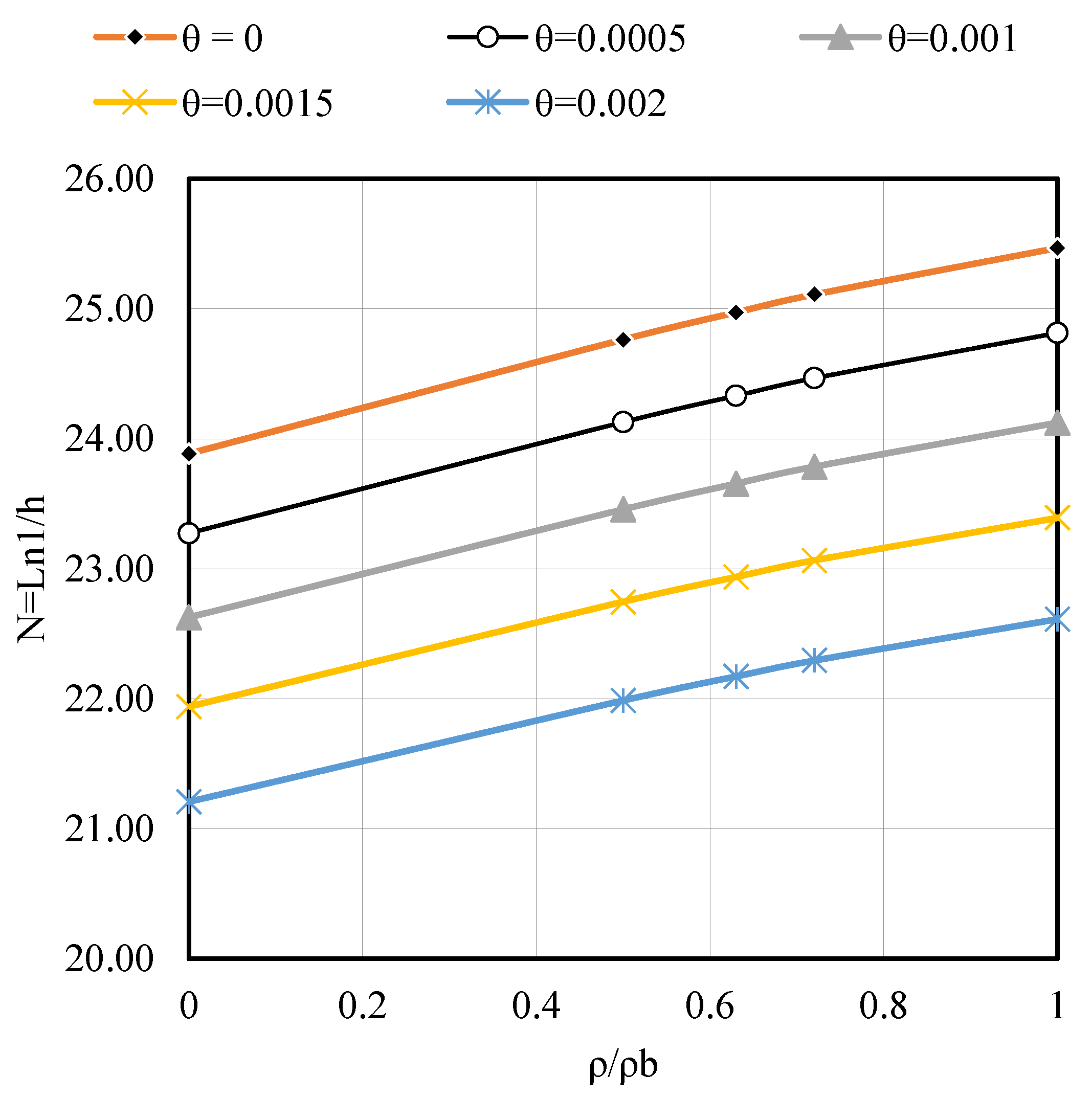
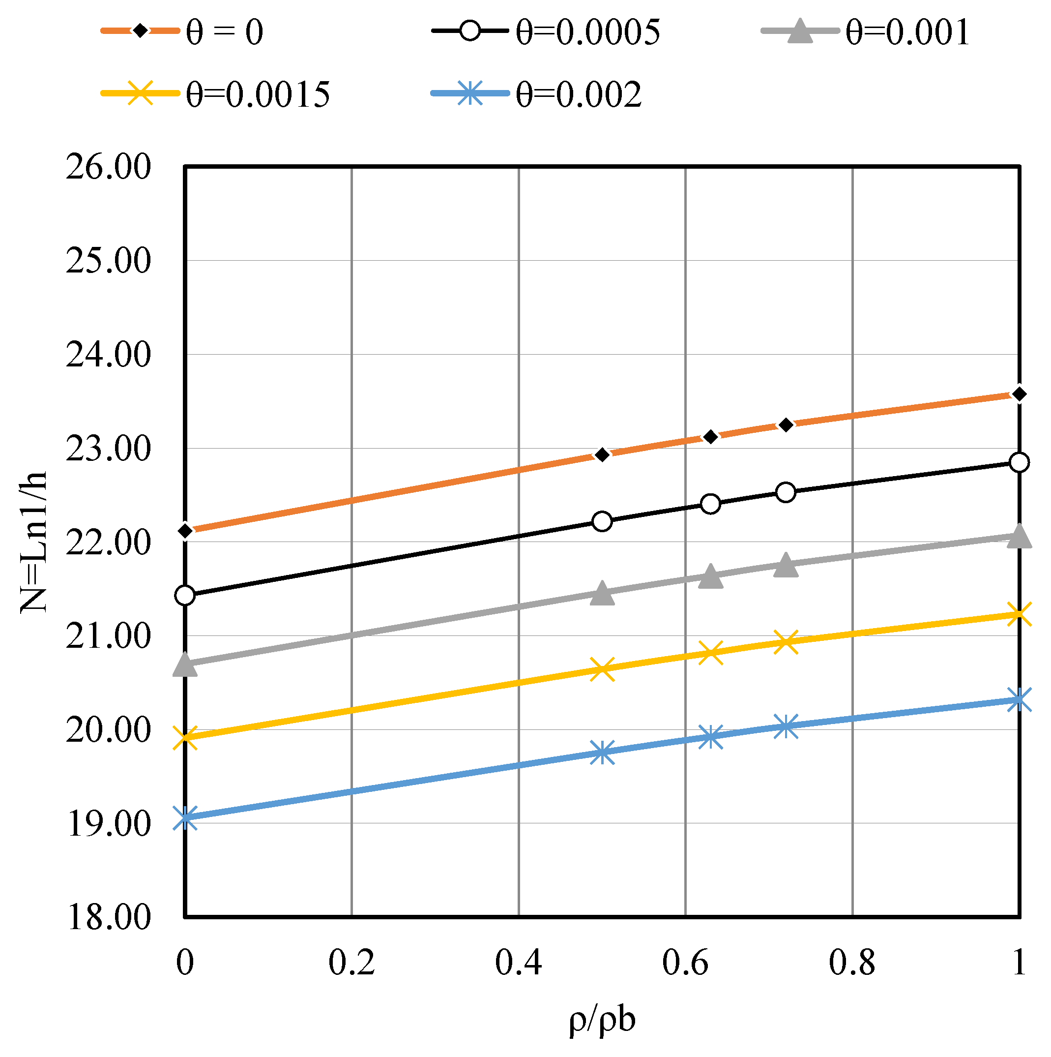
- Figure A3, Figure A4 and Figure A5 clearly illustrate the impact of the reinforcement ratio on the required span–depth ratio (N = L/h) for external slab panels with different aspect ratios β = 1.0, 1.5, and 2.0). As reinforcement increases from β = 0 to 1.0, the required slab thickness consistently decreases, demonstrating the effectiveness of higher steel content in reducing deflection. Notably, for B = 2.0, the effect is more pronounced, indicating greater sensitivity of slender slabs to reinforcement changes.
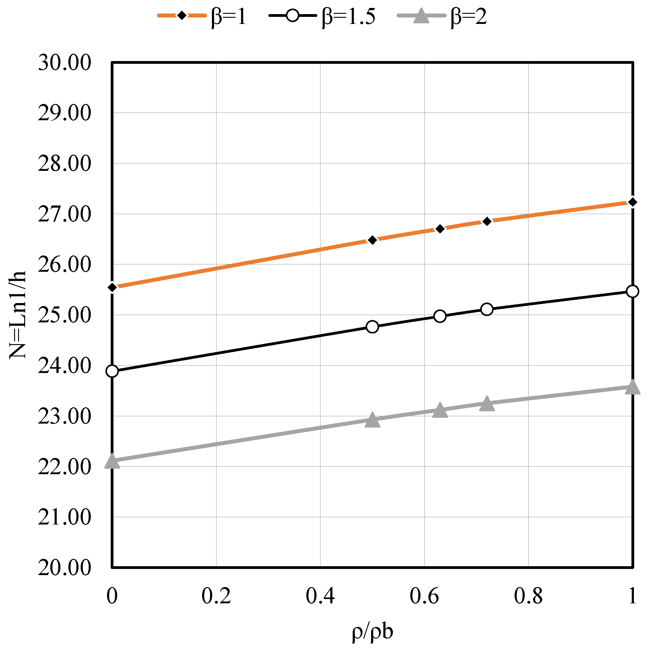
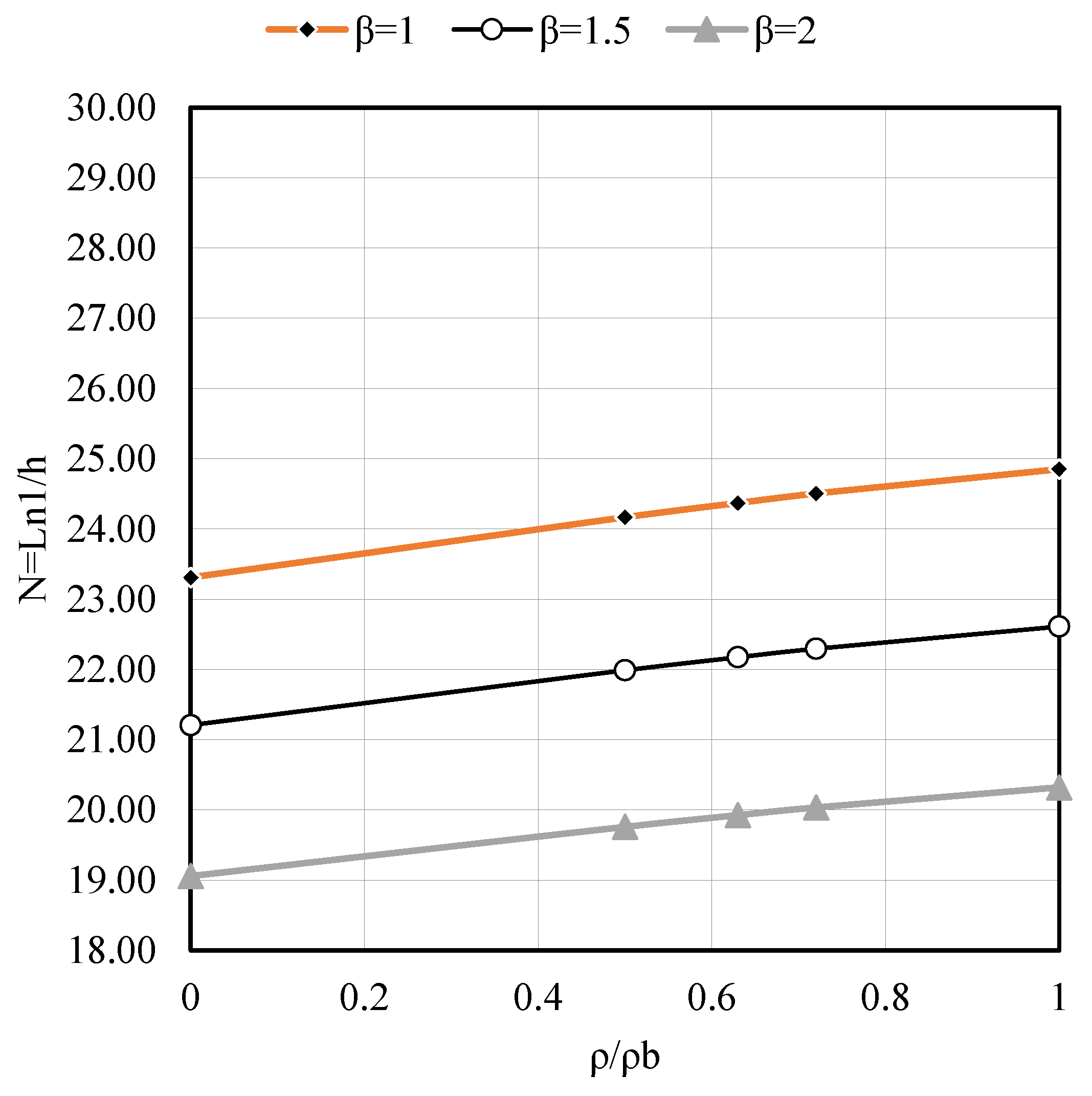
- Figure A6, Figure A7 and Figure A8 highlight that the span–depth ratio decreased with increasing the aspect ratio of the slab (β), i.e., greater thickness is required when the aspect ratio (β) increased from 1 to 2, or in other words, a rectangular slab with (β = 2) required greater thickness than a square slab (β = 1.0); the same conclusion is obtained at support rotation (θ = 0, 0.001 and 0.002).
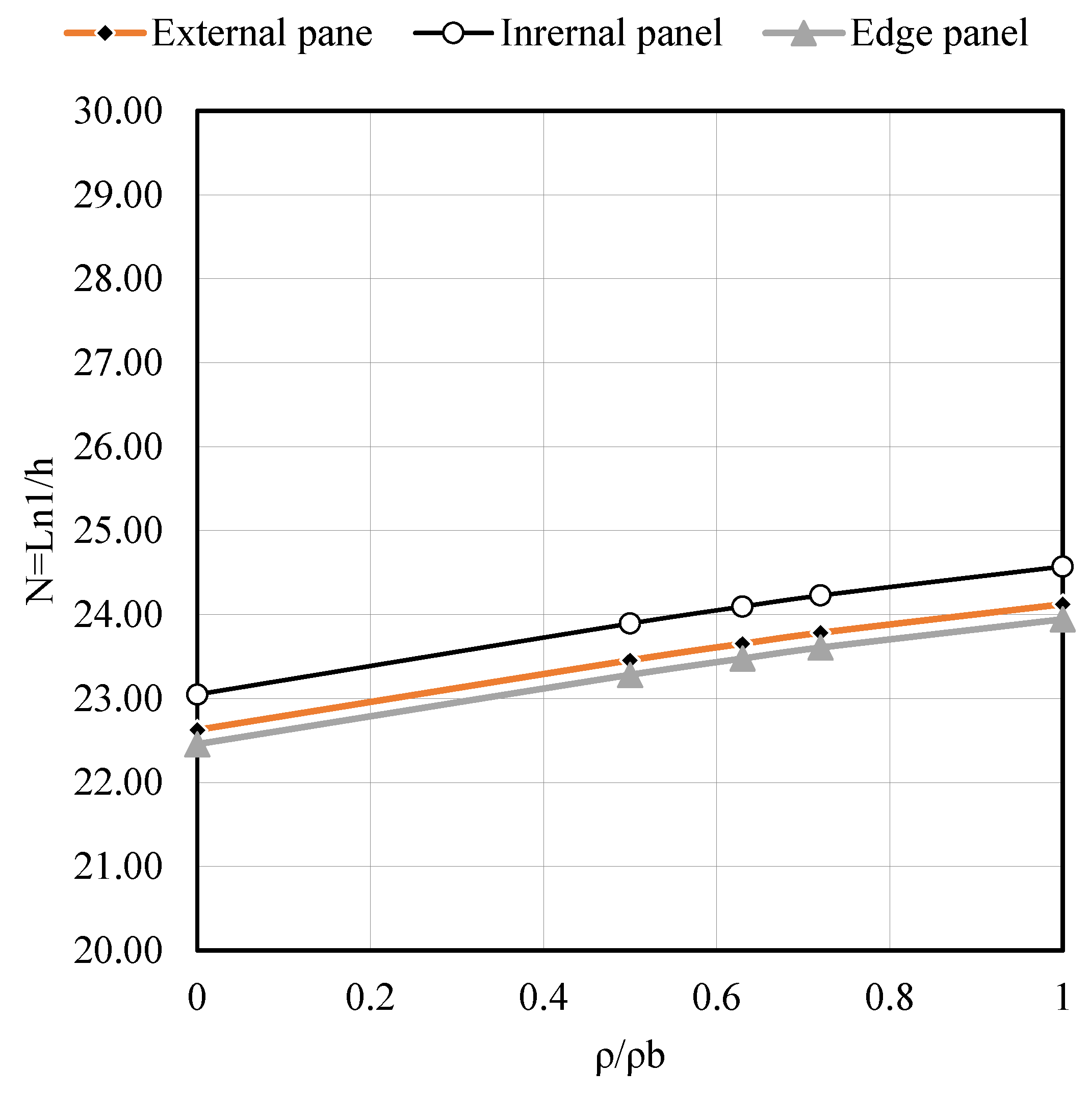
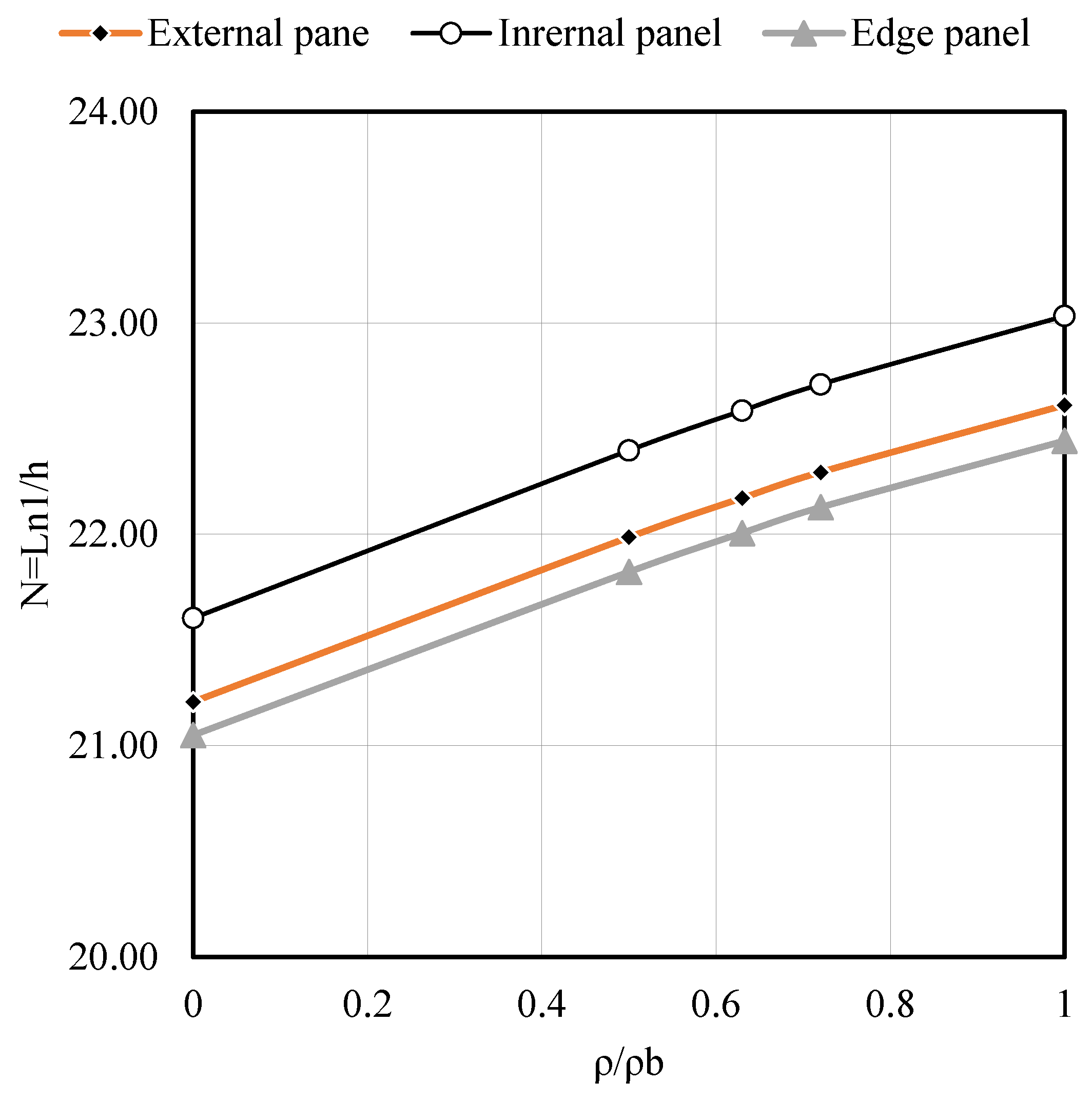
- Figure A9 and Figure A10 show that the span–depth ratio (N) in an interior slab panel is greater than exterior (corner) and edge panels, i.e., exterior (corner) and edge panels required greater thickness than an interior panel, as expected. This behavior is true for any value of the slab aspect ratio (β) and support rotation (θ).
4. Numerical Examples
4.1. Example 1
- Solution:
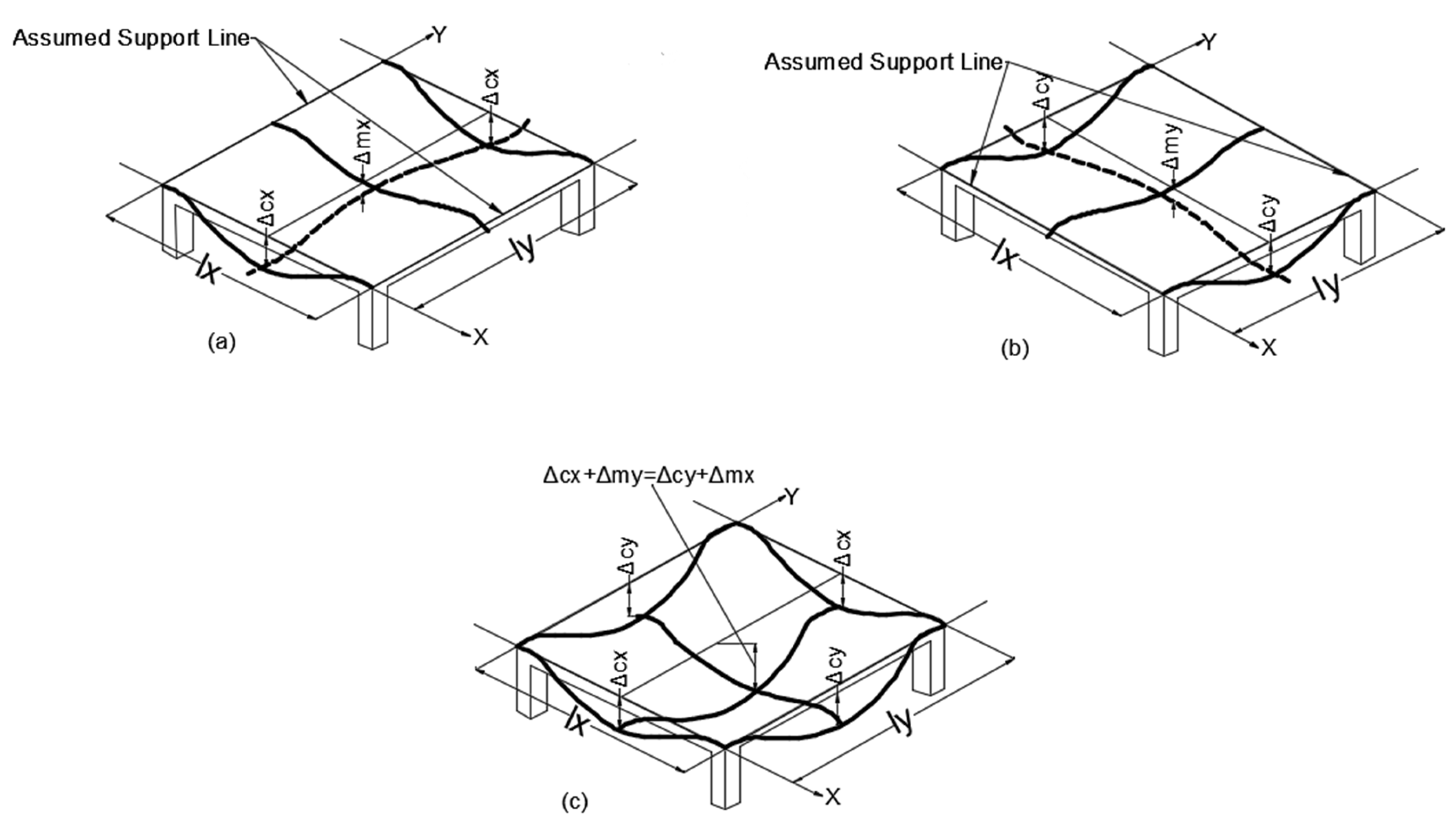
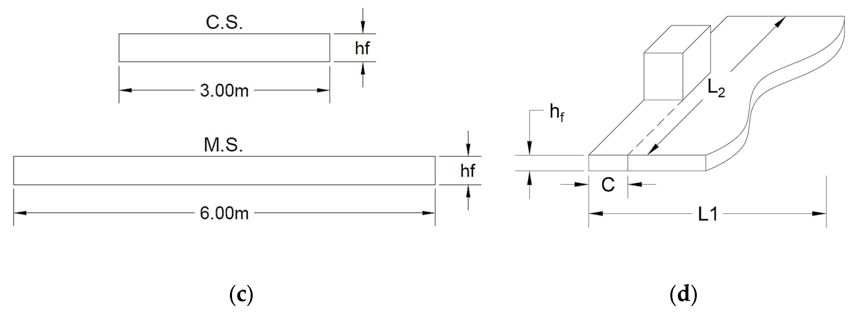
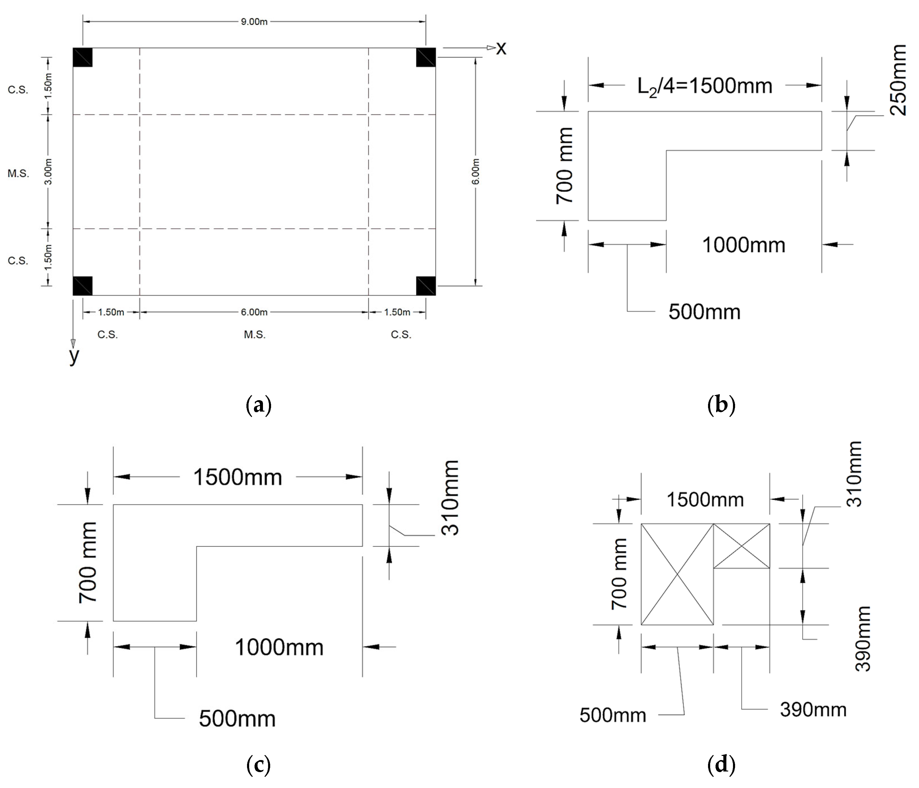
| fc′ = 28 MPa fy = 420 MPa β = 9/6 = 1.5 ρ/ρb = 0.5 Wd.l = 10 kN/m2 = 0.01 N/mm2 WL.L = 20 kN/m2 = 0.02 N/mm2 Assume θx = θy = 0.002 This value reflects an upper-bound estimate based on typical flat slab behavior without edge beams, as observed in validated analytical studies [24,25], and ensures conservative thickness design with respect to ACI deflection limits. From Table A1; hmin = L1/21.9867 = 8500/21.9867 = 386.60 mm ≈ 400 mm - Y-direction: Figure 4b =1.6 × 1010 mm4 - X-direction: Figure 4c =1.6 × 1010 mm4 =3.2 × 1010 mm4 = 25,028.8 MPa For a symmetric external panel; φc = 0.7375; φm = 0.2625; Y-direction For a symmetric external panel; φc = 0.7375; φm = 0.2625; Thuds: Δmax = 1.572 mm Using X-direction: For column (500 × 500) mm & height = 4.0 m Ic = 500 × 5004/12 = 5.2083 × 109 mm4 Kc = 4EI/L = 4 × (5.2083 × 109) (25,028.8)/4000 = 1.3036 × 1011 mm4 C = (1 − 0.63(400/500)) 4003 × 500/3 = 5.29 × 109 mm4 = 2.579 × 10¹¹ N.mm = 0.16 Mo = 0.532 mm - In y-direction =1.5717 × 10¹¹ N.mm = 0.16Mo = 0.2626 mm Short term deflection Or = 0.93 + 0.532 + 0.2626 = 1.7246 mm Short term deflection ) = 3.0, For ; Or = 5(1.7246) = 8.623 mm [Ln2/480 = 5500/480 = 11.458 mm] 11.833 ≈ 11.458 o.k. |
4.2. Example 2
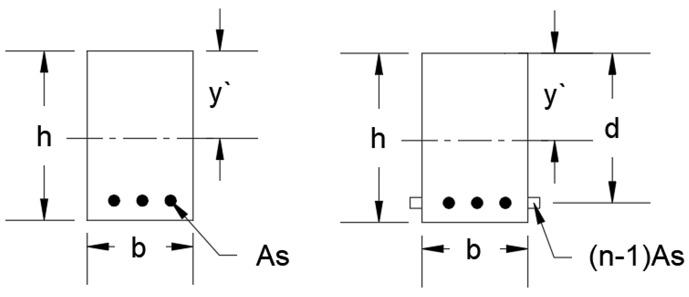
- y′ = 256.25 mm
- Icx = 2.303 × 1010 mm4
| For the middle strips in y-direction (width = 6.0 m), the moment of inertia Imy = 7.8125 × 109 mm4 = 2.944 say 3.0 For the slab with reinforcement ρ/ρb = 0.5 and taking θx = θy = 0.0005 for 1st estimation of the span–depth ratio. φy = 0.52718 and λR = 1.11415 N = 27.957 ≈ 28 hf = Ln/28 = 8500/28 = 303.57 mm ~310 mm Take hf = 310 mm Checking the maximum deflection = 25,028.8 MPa x-direction: for column strip (L2/4 = 1.5 m) and with edge beam (500 × 700 mm) y′ = 256.25 mm Icx = 2.303 × 1010 mm4 For middle strip width (6.0 m) Imy = 1.49 × 1010 mm4 Y-direction: For same edge beams & column strip width, Icy = 2.3031010 mm4. Calculation of the end rotations X-direction For the edge beam, the section is divided in a manner to maximize the torsional constant (C), as the following C = (1 − 0.63(x/y))x3y/3 C1 = (1 − 0.63(500/700))5003(700)/3 = 1.604 × 109 mm4 C2 = (1 − 0.63(310/390))3103(390)/3 = 1.933 × 109 mm4 C = C1+ C2 = 1.797 × 1010 mm4 Or =8.759 × 10¹¹ N.mm Taking column size (500 × 500) mm and height (4.0 m) Ic =5.208 × 109 mm4, Kc = 4EI/L = 1.3036 × 1011 mm4 = 0.16Mo = 0.405 mm - in y-direction = 5.339 × 10¹¹ N.mm = 0.16Mo = 0.179 mm Taking the maximum value in both directions Taking the effect of long term of d.L after (5 years) and adding the effect of live load The ACI-Code maximum limit = Ln2/480 = 5500/480 = 11.458 mm (The thickness (310 mm) satisfy the deflection control limit of ACI-Code. |
5. Conclusions
Funding
Data Availability Statement
Conflicts of Interest
Appendix A
| WDL (N/mm) = | 0.01 | ||||||
| WLL (N/mm) = | 0.02 | ||||||
| β = L1/L2 | 1 | ||||||
| fc′ (Mpa) = | 28 | ||||||
| Ψc = | 0.7375 | ||||||
| Ψm = | 0.2625 | ||||||
| β = L1/L2 | 1 | θ = 0 | θ = 0.0005 | θ = 0.001 | θ = 0.0015 | θ = 0.002 | |
| θ = | 0 | 0.0005 | 0.001 | 0.0015 | 0.002 | ||
| ρ | ρ/ρb | λR | N | N | N | N | N |
| 0 | 0 | 1 | 25.5425 | 25.0211 | 24.4770 | 23.9075 | 23.3096 |
| 0.5ρb | 0.5 | 1.11426 | 26.4805 | 25.9399 | 25.3758 | 24.7855 | 24.1656 |
| ρt | 0.63 | 1.1426 | 26.7031 | 26.1580 | 25.5891 | 24.9938 | 24.3687 |
| ρmax | 0.72 | 1.1617 | 26.8511 | 26.3029 | 25.7309 | 25.1323 | 24.5038 |
| ρb | 1 | 1.212 | 27.2331 | 26.6772 | 26.0971 | 25.4899 | 24.8524 |
| β = L1/L2 | 1.5 | ||||||
| ρ | ρ/ρb | λR | N | N | N | N | N |
| 0 | 0 | 1 | 23.8853 | 23.2726 | 22.6258 | 21.9398 | 21.2079 |
| 0.5ρb | 0.5 | 1.11426 | 24.7624 | 24.1272 | 23.4567 | 22.7454 | 21.9867 |
| ρt | 0.63 | 1.1426 | 24.9706 | 24.3301 | 23.6539 | 22.9366 | 22.1715 |
| ρmax | 0.72 | 1.1617 | 25.1090 | 24.4649 | 23.7849 | 23.0637 | 22.2944 |
| ρb | 1 | 1.212 | 25.4663 | 24.8130 | 24.1234 | 23.3919 | 22.6116 |
| β = L1/L2 | 2 | ||||||
| ρ | ρ/ρb | λR | N | N | N | N | N |
| 0 | 0 | 1 | 22.1156 | 21.4311 | 20.6999 | 19.9131 | 19.0586 |
| 0.5ρb | 0.5 | 1.11426 | 22.9277 | 22.2181 | 21.4601 | 20.6443 | 19.7585 |
| ρt | 0.63 | 1.1426 | 23.1204 | 22.4049 | 21.6405 | 20.8179 | 19.9246 |
| ρmax | 0.72 | 1.1617 | 23.2485 | 22.5291 | 21.7604 | 20.9333 | 20.0350 |
| ρb | 1 | 1.212 | 23.5794 | 22.8496 | 22.0700 | 21.2311 | 20.3201 |
| WDL (N/mm) = | 0.01 | ||||||
| WLL (N/mm) = | 0.02 | ||||||
| β = L1/L2 | 1 | ||||||
| fc′ (Mpa) = | 28 | ||||||
| Ψc = | 0.675 | ||||||
| Ψm = | 0.325 | ||||||
| θ = 0 | θ = 0.0005 | θ = 0.001 | θ = 0.0015 | θ = 0.002 | |||
| θ = | 0 | 0.0005 | 0.001 | 0.0015 | 0.002 | ||
| ρ | ρ/ρb | λR | N | N | N | N | N |
| 0 | 0 | 1 | 25.5425 | 25.0211 | 24.4770 | 23.9075 | 23.3096 |
| 0.5ρb | 0.5 | 1.11426 | 26.4805 | 25.9399 | 25.3758 | 24.7855 | 24.1656 |
| ρt | 0.63 | 1.1426 | 26.7031 | 26.1580 | 25.5891 | 24.9938 | 24.3687 |
| ρmax | 0.72 | 1.1617 | 26.8511 | 26.3029 | 25.7309 | 25.1323 | 24.5038 |
| ρb | 1 | 1.212 | 27.2331 | 26.6772 | 26.0971 | 25.4899 | 24.8524 |
| β = L1/L2 | 1.5 | ||||||
| ρ | ρ/ρb | λR | N | N | N | N | N |
| 0 | 0 | 1 | 24.3310 | 23.7068 | 23.0479 | 22.3491 | 21.6036 |
| 0.5ρb | 0.5 | 1.11426 | 25.2244 | 24.5774 | 23.8943 | 23.1698 | 22.3969 |
| ρt | 0.63 | 1.1426 | 25.4365 | 24.7840 | 24.0952 | 23.3646 | 22.5852 |
| ρmax | 0.72 | 1.1617 | 25.5775 | 24.9213 | 24.2287 | 23.4940 | 22.7103 |
| ρb | 1 | 1.212 | 25.9414 | 25.2759 | 24.5735 | 23.8284 | 23.0335 |
| β = L1/L2 | 2 | ||||||
| ρ | ρ/ρb | λR | N | N | N | N | N |
| 0 | 0 | 1 | 22.6651 | 21.9637 | 21.2143 | 20.4079 | 19.5322 |
| 0.5ρb | 0.5 | 1.11426 | 23.4974 | 22.7702 | 21.9934 | 21.1574 | 20.2495 |
| ρt | 0.63 | 1.1426 | 23.6950 | 22.9617 | 22.1783 | 21.3352 | 20.4197 |
| ρmax | 0.72 | 1.1617 | 23.8263 | 23.0889 | 22.3012 | 21.4535 | 20.5329 |
| ρb | 1 | 1.212 | 24.1653 | 23.4174 | 22.6185 | 21.7587 | 20.8250 |
| WDL (N/mm) = | 0.01 | ||||||
| WLL (N/mm) = | 0.02 | ||||||
| β = L1/L2 | 1 | ||||||
| fc′ (Mpa) = | 28 | ||||||
| Ψc = | 0.7375 | ||||||
| Ψm = | 0.325 | ||||||
| θ = 0 | θ = 0.0005 | θ = 0.001 | θ = 0.0015 | θ = 0.002 | |||
| θ = | 0 | 0.0005 | 0.001 | 0.0015 | 0.002 | ||
| ρ | ρ/ρb | λR | N | N | N | N | N |
| 0 | 0 | 1 | 25.0315 | 24.5205 | 23.9873 | 23.4293 | 22.8433 |
| 0.5ρb | 0.5 | 1.11426 | 25.9507 | 25.4210 | 24.8682 | 24.2896 | 23.6821 |
| ρt | 0.63 | 1.1426 | 26.1689 | 25.6347 | 25.0772 | 24.4938 | 23.8812 |
| ρmax | 0.72 | 1.1617 | 26.3139 | 25.7767 | 25.2162 | 24.6295 | 24.0135 |
| ρb | 1 | 1.212 | 26.6883 | 26.1435 | 25.5750 | 24.9800 | 24.3552 |
| β = L1/L2 | 1.5 | ||||||
| ρ | ρ/ρb | λR | N | N | N | N | N |
| 0 | 0 | 1 | 23.7072 | 23.0990 | 22.4570 | 21.7761 | 21.0497 |
| 0.5ρb | 0.5 | 1.11426 | 24.5777 | 23.9473 | 23.2817 | 22.5758 | 21.8227 |
| ρt | 0.63 | 1.1426 | 24.7844 | 24.1486 | 23.4774 | 22.7656 | 22.0061 |
| ρmax | 0.72 | 1.1617 | 24.9217 | 24.2824 | 23.6075 | 22.8917 | 22.1281 |
| ρb | 1 | 1.212 | 25.2763 | 24.6279 | 23.9435 | 23.2174 | 22.4429 |
| β = L1/L2 | 2 | ||||||
| ρ | ρ/ρb | λR | N | N | N | N | N |
| 0 | 0 | 1 | 22.0413 | 21.3592 | 20.6304 | 19.8462 | 18.9946 |
| 0.5ρb | 0.5 | 1.11426 | 22.8507 | 22.1435 | 21.3880 | 20.5750 | 19.6921 |
| ρt | 0.63 | 1.1426 | 23.0428 | 22.3297 | 21.5678 | 20.7480 | 19.8577 |
| ρmax | 0.72 | 1.1617 | 23.1705 | 22.4534 | 21.6873 | 20.8630 | 19.9677 |
| ρb | 1 | 1.212 | 23.5002 | 22.7729 | 21.9959 | 21.1598 | 20.2518 |
| External Slab Panel | |||||||
|---|---|---|---|---|---|---|---|
| Maximum deflection limit (Ln/480) | |||||||
| WDL (N/mm2) = | 0.01 | ||||||
| WLL (N/mm2) = | 0.02 | ||||||
| β = L1/L2 | 1 | ||||||
| fc′ (Mpa) = | 28 | ||||||
| Ψc = | 0.7375 | ||||||
| Ψm = | 0.2625 | ||||||
| A = | 3 | ||||||
| β = 1 | θ = 0 | θ = 0.0005 | θ = 0.001 | θ = 0.0015 | θ = 0.002 | ||
| θ = | 0 | 0.0005 | 0.001 | 0.0015 | 0.002 | ||
| ρ | ρ/ρb | λR | N | N | N | N | N |
| 0 | 0 | 1 | 21.6328 | 21.1912 | 20.7304 | 20.2481 | 19.7417 |
| 0.5ρb | 0.5 | 1.11426 | 22.4272 | 21.9694 | 21.4916 | 20.9916 | 20.4666 |
| ρt | 0.63 | 1.1426 | 22.6158 | 22.1541 | 21.6723 | 21.1681 | 20.6387 |
| ρmax | 0.72 | 1.1617 | 22.7411 | 22.2768 | 21.7924 | 21.2854 | 20.7531 |
| ρb | 1 | 1.212 | 23.0647 | 22.5938 | 22.1025 | 21.5883 | 21.0484 |
| β = L1/L2 | 1.5 | ||||||
| ρ | ρ/ρb | λR | N | N | N | N | N |
| 0 | 0 | 1 | 27.6780 | 26.9680 | 26.2185 | 25.4235 | 24.5754 |
| 0.5ρb | 0.5 | 1.11426 | 28.6944 | 27.9583 | 27.1813 | 26.3571 | 25.4778 |
| ρt | 0.63 | 1.1426 | 28.9356 | 28.1933 | 27.4098 | 26.5787 | 25.6920 |
| ρmax | 0.72 | 1.1617 | 29.0959 | 28.3496 | 27.5617 | 26.7259 | 25.8344 |
| ρb | 1 | 1.212 | 29.5100 | 28.7530 | 27.9538 | 27.1062 | 26.2020 |
| β = L1/L2 | 2 | ||||||
| ρ | ρ/ρb | λR | N | N | N | N | N |
| 0 | 0 | 1 | 30.2581 | 29.3217 | 28.3213 | 27.2448 | 26.0757 |
| 0.5ρb | 0.5 | 1.11426 | 31.3693 | 30.3984 | 29.3613 | 28.2452 | 27.0332 |
| ρt | 0.63 | 1.1426 | 31.6330 | 30.6540 | 29.6082 | 28.4827 | 27.2605 |
| ρmax | 0.72 | 1.1617 | 31.8083 | 30.8239 | 29.7722 | 28.6405 | 27.4115 |
| ρb | 1 | 1.212 | 32.2609 | 31.2625 | 30.1959 | 29.0481 | 27.8016 |
Appendix B




References
- ACI 318-25; Building Code Requirements for Structural Concrete and Commentary. American Concrete Institute: Farmington Hills, MI, USA, 2025.
- Darwin, D.; Dolon, C.W.; Nilson, A.H. Design of Concrete Structures, 15th ed.; McGraw Hill Education (India) Private Limited: Chennai, India, 2016; 786p. [Google Scholar]
- Wight, J.K.; mac Gregor, J.G. Reinforced Concrete Materials and Design, 5th ed.; Pearson Prentice Hall: Hoboken, NJ, USA, 2009; 1128p. [Google Scholar]
- Mc Cormac JCand Nelson, J.K. Design of Reinforced Concrete, 7th ed.; John Wiley & Sons: Hoboken, NJ, USA, 2006; 721p. [Google Scholar]
- Ghali, A.; Faure, R.; Elbadry, M. Concrete Structures, 3rd ed.; E & FN Epson: London, UK, 2002; 584p. [Google Scholar]
- Jiang, W.; Zheng, X. Applied research on the minimum thickness of leveling layer of non-adhesive flat extruded board system. Appl. Sci. 2022, 12, 4673. [Google Scholar] [CrossRef]
- Wang, J.; Kusunoki, K. An Effective Beam Width Model of Slab in Thick Wall-Thick Slab Joints Subjected to Lateral Forces. Appl. Sci. 2022, 12, 4600. [Google Scholar] [CrossRef]
- Hwang, H.J.; Ma, G. Minimum thickness of flat plates considering construction load effect. Structural Engineering and Mechanics. Struct. Eng. Mech. 2019, 69, 1–10. [Google Scholar]
- Aidy, A.; Rady, M.; Mashhour, I.M.; Mahfouz, S.Y. Structural design optimization of flat slab hospital buildings using genetic algorithms. Buildings 2022, 12, 2195. [Google Scholar] [CrossRef]
- Al-Zahra, B.I.A.; Alwash, M.; Baiee, A.; Shubbar, A.A. Limitations on ACI code minimum thickness requirements for flat slab. Civ. Eng. J. 2021, 7, 1918–1932. [Google Scholar] [CrossRef]
- Stochino, F.; Lopez Gayarre, F. Reinforced concrete slab optimization with simulated annealing. Appl. Sci. 2019, 9, 3161. [Google Scholar] [CrossRef]
- Lee, Y.H.; Kim, M.S.; Lee, J.; Scanion, A. Comparison of Minimum Thickness Provisions for Concrete Beams in Building Codes and Standard. Can. J. Civ. Eng. 2013, 6, 595–602. [Google Scholar] [CrossRef]
- Beal, A.N.; Thomoson, R.H. Span/Depth ratio for Concrete Beams and Slabs. Struct. Eng. 1983, 61A, 1–8. [Google Scholar]
- Shelata, I.A.E.M.; Shelata, L.C.D.; Garcia, S.L.G. Minimum Steel ratios in Reinforced Concrete Beams Made of Concrete with Different Strength-Theoreticcal Approach. Mater. Struct. 2003, 63, 3–11. [Google Scholar]
- Ho, J.C.M.; Kwan, A.K.H.; Pam, H.J. Minimum Flexural Ductility Design of High Strength Concrete Beams. Mag. Concr. Res. 2004, 56, 13–22. [Google Scholar] [CrossRef]
- Akmalnddin, A. Effect of Tensile Reinforced Ratio on the Effective Moment of Inertia of Reinforced Light Weight Concrete Beams for Short Term Deflection Calculation. ITB J. Eng. Sci. 2011, 43, 209–226. [Google Scholar] [CrossRef][Green Version]
- Oruin, M.M.; Anik, K.A. Minimum Slab Thickness Reqirement of RCC Slab in Order to Prevent Undesirable Floor Vibration. Int. J. Advaces Mech. Civ. Eng. 2016, 3, 2394–2827. [Google Scholar]
- Zahid, T.B.; Amanat, K.M. Minimum thickness of solid concrete floor slab with column line beams to avoid walking vibration discomfort. Struct. Concr. 2022, 23, 3511–3520. [Google Scholar] [CrossRef]
- Ghalla, M.; Badawi, M.; Hu, J.W.; Elsamak, G.; Mlybari, E.A.; Emara, M. Ultimate performance of two-way reinforced concrete flat slabs enhanced by SHCC drop panels mitigating punching failure. J. Build. Eng. 2025, 99, 111574. [Google Scholar] [CrossRef]
- Ghalla, M.; Mansour, W.; Li, W.; Wang, P.; Badawi, M.; El Zareef, M.A. Enhancing the punching performance of two-way RC flat slabs using different configurations of embedded aluminum sections: Experimental program and numerical analysis. Constr. Build. Mater. 2024, 434, 136737. [Google Scholar] [CrossRef]
- Elsamak, G.; Ghalla, M.; Badawi, M.; Albogami, A.; Tawfik, T.A.; Shahin, R.I. Anchored and Epoxied Ferrocement Strips for Improving Flexural Performance of Two-Way Reinforced Concrete Slabs. Case Stud. Constr. Mater. 2025, 22, e04314. [Google Scholar] [CrossRef]
- Islamkhan, M.R.; Hakimkhan, Z.; Raiyan, M.F.; Amanat, K.M. Minimum Slab Thickness of RC Slab to Pevent Undesirable Floor Vibration. In Proceedings of the 2013 World Conference on Advance in Structural Engineering and Mechanics (ASEM13), Jeju, Korea, 8–12 September 2013; pp. 1886–1899. [Google Scholar]
- Heneash, U.; Ghalla, M.; Tawfik, T.A.; Elsamak, G.; Emara, M.; Basha, A. Impact of various dowel bars techniques in joints of plain concrete connected rigid pavements: Experimental and numerical investigations. Results Eng. 2025, 25, 103858. [Google Scholar] [CrossRef]
- Sarkawt, A.H.; Bahman, O.T. Aspect Ratio Consideration in Flat Plate Concrete Slab Deflection. Zanco J. Pure Appl. Sci. 2020, 32, 62–77. [Google Scholar]
- Lee, Y.H.; Scanlon, A. Comparison of One-and Two-Way Slab Minimum Thickness Provisions in Building Codes and Standards. ACI Struct. J. 2010, 107, 157–163. [Google Scholar]
- Elgohary, H.A.; El Zareef, M.A. Refined span-to-depth ratio expressions for one-way slabs aligned with ACI-318 deflection limits. J. Umm Al-Qura Univ. Eng. Archit. 2025, 16, 361–369. [Google Scholar] [CrossRef]
- El Zareef, M.A.; Ghalla, M.; Hu, J.W.; Elbisy, A.M. Machine learning approaches for estimating concrete shear strength in FRP reinforced members without shear reinforcement. Steel Compos. Struct. 2024, 53, 327. [Google Scholar]
- Elsamak, G.; Alkhawaldeh, A.A.; Badawi, M.; Alshammari, E.; Tawfik, T.A.; Ghalla, M. Externally bonded and anchored engineered cementitious composite and glass fiber mesh strips for enhancing defected RC beams in shear. Case Stud. Constr. Mater. 2025, 22, e04385. [Google Scholar] [CrossRef]


| Support Condition | Minimum Thickness |
|---|---|
| Simply Supported | l/20 |
| One–end continuous | l/24 |
| Both ends continuous | l/28 |
| Cantilever | l/10 |
| fy MPa | Without Drop Panels | With Drop Panels | ||||
|---|---|---|---|---|---|---|
| Exterior Panels | Interior Panels | Exterior Panels | Interior Panels | |||
| Without Edge Beams | With Edge Beams | Without Edge Beams | With Edge Beams | |||
| 280 | Ln/33 | Ln/36 | Ln/36 | Ln/36 | Ln/40 | Ln/40 |
| 420 | Ln/30 | Ln/33 | Ln/33 | Ln/33 | Ln/36 | Ln/36 |
| 520 | Ln/28 | Ln/31 | Ln/31 | Ln/31 | Ln/34 | Ln/34 |
| Member | Condition | Deflection to Be Considered | Deflection Limitation | |
|---|---|---|---|---|
| Flat roofs | Not supporting or attached to nonstructural elements likely to be damaged by large deflections | Immediate deflection due to maximum of Lr, S, and R | L/180 | |
| Floors | Immediate deflection due to L | L/360 | ||
| Roof or floors | Supporting or attached to nonstructural elements | Likely to be damaged by large deflections | That part of the total deflection occurring after attachment of nonstructural elements, which is the sum of the time-dependent deflection due to all sustained loads and the immediate deflection due to any additional live load | L/480 |
| Not likely to be damaged by large deflections | L/240 | |||
| (a) | (b) | (c) | (d) | (e) | |
|---|---|---|---|---|---|
| Exterior Edge Unrestrained | Slab with Beams Between All Supports | Slab Without Beams Between Interior Supports | Exterior Edge Fully Restrained | ||
| Without Edge Beam | With Edge Beam | ||||
| Interior negative moment | 0.75 | 0.70 | 0.70 | 0.70 | 0.65 |
| Positive moment | 0.63 | 0.57 | 0.52 | 0.50 | 0.35 |
| Exterior negative moment | 0 | 0.16 | 0.26 | 0.30 | 0.65 |
| L2/L1 | ||||
|---|---|---|---|---|
| 0.50 | 1.0 | 2.0 | ||
| Interior negative moment | ||||
| αf1 L2/L1 = 0 | 75 | 75 | 75 | |
| αf1 L2/L1 ≥ 1.0 | 90 | 75 | 45 | |
| Exterior negative moment | ||||
| αf1 L2/L1 = 0 | βt = 0 | 100 | 100 | 100 |
| βt ≥ 0 | 75 | 75 | 75 | |
| αf1 L2/L1 ≥ 1.0 | βt = 0 | 100 | 100 | 100 |
| βt ≥ 0 | 90 | 75 | 45 | |
| Positive moment | ||||
| αf1 L2/L1 = 0 | 60 | 60 | 60 | |
| αf1 L2/L1 ≥ 1.0 | 90 | 75 | 45 | |
| Maximum Deflection Limit | α1 | α2 |
|---|---|---|
| L/180 | 7.50 | 22.50 |
| L/360 | 5.95 | 45.00 |
| L/480 | 5.40 | 60.00 |
| L/240 | 6.80 | 30.00 |
| Maximum Deflection Limit | α1 | α2 |
|---|---|---|
| L/180 | 5.06 | 22.50 |
| L/360 | 4.00 | 45.00 |
| L/480 | 3.65 | 60.00 |
| L/240 | 4.60 | 30.00 |
Disclaimer/Publisher’s Note: The statements, opinions and data contained in all publications are solely those of the individual author(s) and contributor(s) and not of MDPI and/or the editor(s). MDPI and/or the editor(s) disclaim responsibility for any injury to people or property resulting from any ideas, methods, instructions or products referred to in the content. |
© 2025 by the author. Licensee MDPI, Basel, Switzerland. This article is an open access article distributed under the terms and conditions of the Creative Commons Attribution (CC BY) license (https://creativecommons.org/licenses/by/4.0/).
Share and Cite
Taha, B.O. A Generalized Span–Depth Ratio Model for Minimum Thickness Design of Flat Plate Slabs Incorporating ACI Deflection Criteria. Buildings 2025, 15, 2157. https://doi.org/10.3390/buildings15132157
Taha BO. A Generalized Span–Depth Ratio Model for Minimum Thickness Design of Flat Plate Slabs Incorporating ACI Deflection Criteria. Buildings. 2025; 15(13):2157. https://doi.org/10.3390/buildings15132157
Chicago/Turabian StyleTaha, Bahman Omar. 2025. "A Generalized Span–Depth Ratio Model for Minimum Thickness Design of Flat Plate Slabs Incorporating ACI Deflection Criteria" Buildings 15, no. 13: 2157. https://doi.org/10.3390/buildings15132157
APA StyleTaha, B. O. (2025). A Generalized Span–Depth Ratio Model for Minimum Thickness Design of Flat Plate Slabs Incorporating ACI Deflection Criteria. Buildings, 15(13), 2157. https://doi.org/10.3390/buildings15132157


