1. Introduction
With the continuous advancement and development of urban planning, during the excavation of subway tunnels, it is inevitable to encounter situations where existing buildings or preceding tunnels are located near shield tunnels. The construction of new tunnels significantly disturbs surrounding soils, affecting the safety and stability of adjacent structures and existing tunnels. Severe impacts may even create construction hazards [
1]. Therefore, for small-clear-distance shield tunnel construction in practical engineering, it is crucial to establish special safety construction schemes, investigate their feasibility and effectiveness, and ensure project completion.
Since the emergence of issues related to small-clear-distance shield tunnel construction, numerous scholars have conducted extensive research and achieved remarkable results. Pan Qian et al. [
2] addressed construction challenges in small-clear-distance tunnels through different lithological contact zones by combining numerical simulations to determine reasonable construction sequences and technical measures. Li Ran et al. [
3,
4] systematically investigated the stability characteristics of surrounding rock in three-bore small-clear-distance tunnel projects, proposed corresponding control methods, and conducted engineering applications. They also thoroughly studied the construction mechanical behaviors and control mechanisms through numerical simulations and field measurements. An Jianyong et al. [
5] derived full-process surface settlement characteristics through field data analysis and proposed settlement control measures. Ning Bo [
6] applied the WSS method to grout-reinforce tunnel excavation sections in high-water-level small-clear-distance tunnels, modified grid steel frames, optimized grouting procedures, and accelerated construction progress. Zhou Jingzeng et al. [
7] addressed the construction challenges of small-clear-distance overlapping shield tunnels in soft soil by proposing a “lower-first-then-upper” construction sequence, reducing difficulties and improving quality control. Fu Zhao et al. [
8] conducted finite element simulations to analyze mutual influences during small-clear-distance shield tunneling, performed sensitivity analysis on shield parameters, and determined optimal excavation sequences. Song Gaorui et al. [
9] optimized construction methods for small-clear-distance parallel tunneling through shield and shallow buried excavation based on practical projects. Hu Ping et al. [
10] simulated deformation patterns of preceding shallow buried tunnels under various small-clear-distance conditions during shield tunneling, proposing practical reinforcement measures. Wang Zhuangzhuang et al. [
11] analyzed contour deformation characteristics of new and existing tunnels under four small-clear-distance conditions, along with displacement-excavation step relationships. Wu Kai et al. [
12] investigated deformation and internal force distribution in adjacent soils, anti-floating slabs, and existing tunnels during shield advancement using finite element software.
Ref. [
13] proposed a three-dimensional Peck formula for the Jilu Road undercrossing the Yellow River Levee, optimizing the settlement prediction model through field-measured data fitting and revealing the influence of vertical depth and tunnel spacing on settlement trough morphology. Ref. [
14], focusing on the Beijing Metro Line 17 undercrossing the North Fourth Ring Road, achieved a maximum surface settlement control of 7.618 mm through test section parameter optimization and numerical simulation, verifying the effectiveness of dynamic adjustment of excavation parameters. Ref. [
15] for the Shanghai Metro Line 18 undercrossing ballasted railway tracks in soft soil developed a “fine shield construction control method,” coordinating soil chamber pressure and grouting volume to limit subgrade deformation within ±10 mm. Ref. [
16] adopted advanced large pipe shed, composite three-layer lining, and interlayer soil grouting reinforcement in the Chengdu Metro Line 13 mining method tunnel to suppress the “horizontal oval” deformation of existing tunnels during ultra-small-clear-distance undercrossing, ensuring structural safety. Ref. [
17] proposed a collaborative bearing technology of advanced pipe shed and deep-hole grouting for the Beijing Metro Line 12 double-interval undercrossing project, locking key disturbance areas via numerical simulation and controlling deformation of existing shield structures within 5.0 mm.
Ref. [
18] analyzed the influence of pile–tunnel spacing on pile foundation internal forces using Midas-GTS 3D modeling for the Hefei Metro Line 7 shield undercrossing existing piles, validating safety assessment methods through field monitoring. Ref. [
19] innovatively applied post-wall compensation grouting, Clayshock grouting method, and fully automated monitoring in the Wuhan Metro Line 7 ultra-close undercrossing project, achieving micro-settlement control (<1 mm) and optimizing traditional advanced pipe shed schemes. Ref. [
20] revealed the soil–structure interaction mechanism during a metro tunnel undercrossing an underground passage via numerical simulation, identifying the barrier effect of existing structures on soil arching and the lagging deformation in the trailing side. Ref. [
21] controlled the inclination rate of high-voltage transmission towers within −0.1‰~0.14‰ by staging propulsion parameter adjustment, synchronous grouting, and Clayshock injection for the Shanghai Airport Link large-diameter shield project. Ref. [
22], for the Chengdu Metro Line 30 undercrossing an expressway in composite strata, confirmed through 3D numerical modeling that radial reinforcement depth is more effective than circumferential angle for settlement control, validating the scheme via field measurements.
Current research on small-clear-distance shield tunneling primarily focuses on optimizing construction techniques and soil reinforcement through grouting. This paper presents a special safety construction scheme for horizontal small-clear-distance shield tunneling based on practical engineering experience. By employing grouting reinforcement to reduce overall deformation, Midas GTS(2022R1) finite element software was utilized to simulate construction processes and analyze grouting effectiveness. Combined with field monitoring data, the scheme was comprehensively evaluated to ensure feasibility. The work presented herein provides valuable references for research on horizontal small-clear-distance shield tunneling technologies.
2. Project Overview
2.1. Design Overview
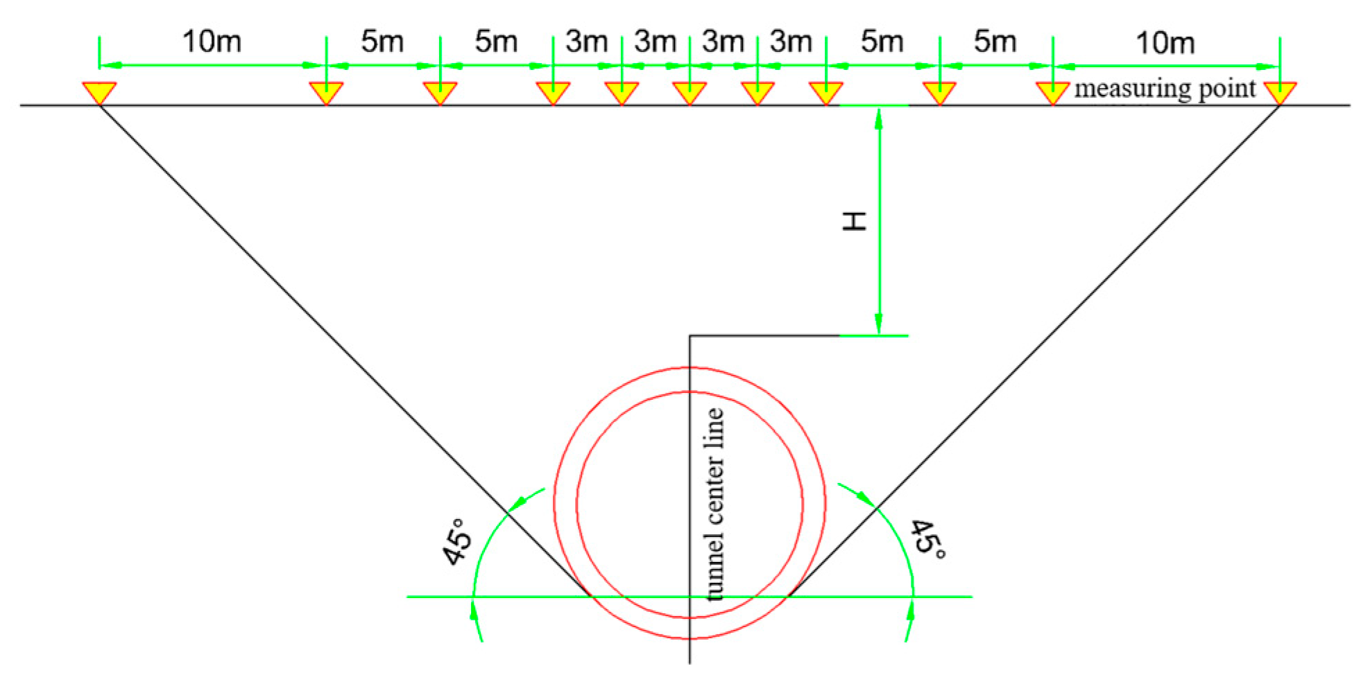
The tunnel design for the Congbian Road Station to Jiansheliu Road Station section of Guangzhou Metro Line 13 adopts double-track circular tunnels. As shown in
Figure 1. The shield tunnel has an excavation diameter of 6680 mm. The lining rings utilize universal wedge rings with a “3 + 2 + 1” segmented configuration, assembled in a staggered joint pattern. Simultaneous grout back-filling is applied behind the segments. The tunnel segments are constructed using C50 high-performance concrete with an impermeability grade of P12. Key segment specifications include an outer diameter of 6400 mm, inner diameter of 5800 mm, ring width of 1500 mm, and a double-sided taper with a total lining taper amount of 48 mm.
The tunnel alignment features a maximum downhill gradient of 20‰ and a minimum gradient of 3.237‰. The minimum overburden depth at the tunnel crown is approximately 18.0 m, while the maximum overburden depth reaches 26.3 m.
2.2. Engineering Geological Conditions
This section features a landscape of clastic rock low hill platforms and inter-hill alluvial valleys, with slightly undulating terrain and a ground elevation of 8–12 m. The alignment primarily follows East Fengdong Road, intersects with multiple subway lines, and exhibits highly complex alignment conditions. The bedrock consists of sedimentary rocks, while the residual soil is predominantly silty clay in a plastic-to-hard-plastic state, demonstrating favorable engineering properties. The completely weathered layer presents as hard silty clay-like or dense silt-like material, also with good engineering properties. The highly weathered rock exhibits a semi-rock and semi-soil mass or fragmented blocks with developed weathering fissures, classified as extremely soft rock with poor rock mass integrity. It is prone to softening upon water absorption and desiccation-induced cracking when dehydrated. Due to variations in cementing materials and the degree of structural plane development, the weathered rocks display uneven weathering. Vertically, interlayered zones of differing weathering grades frequently occur, leading to significant variations and disparities in the mechanical strength of the rock mass.
The tunnel section exhibits a stable water table depth ranging from 1.9 to 4.9 m, with an average depth of 3.23 m. The groundwater primarily consists of Quaternary pore water aquifers, bedrock fissure water aquifers, and relatively impermeable layers. It maintains a hydraulic connection with surface water, sharing a unified free water surface. Overall, the groundwater is confined, though localized unconfined water zones exist in certain segments. Based on comprehensive observations from monitoring wells, the water head elevation can be conservatively estimated at 1 m below the ground surface.
2.3. Project Highlights and Difficulties
2.3.1. The Shield Machine Cutterhead Is Prone to Mud Cake Formation
The tunnel section at Congbian Road Station traverses moderately weathered and slightly weathered argillaceous siltstone formations. Historical construction experience indicates that argillaceous siltstone—characterized by its high content of clay mineral particles and fine powder—exhibits significant susceptibility to mud cake formation during shield tunneling operations.
2.3.2. The Deformation Risk of Shield Tunneling with a Small Clear Distance Passing by Existing Buildings and Structures on the Side and Passing Under Groups of Buildings and Structures
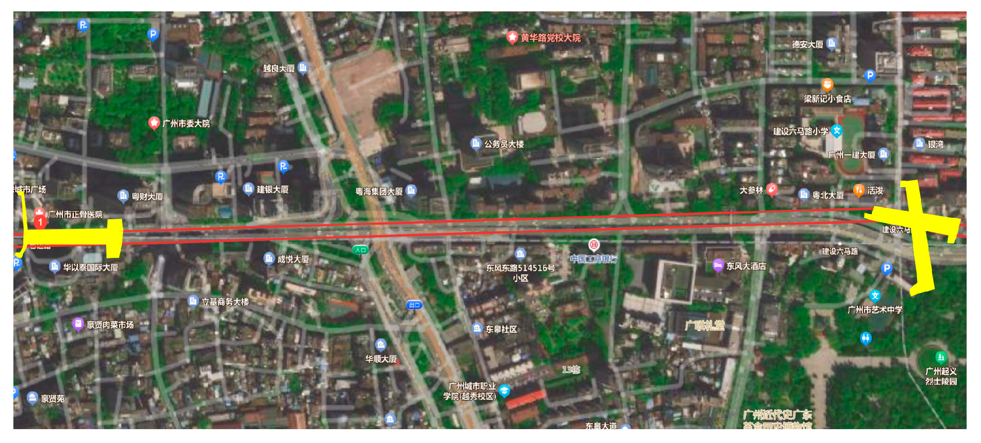
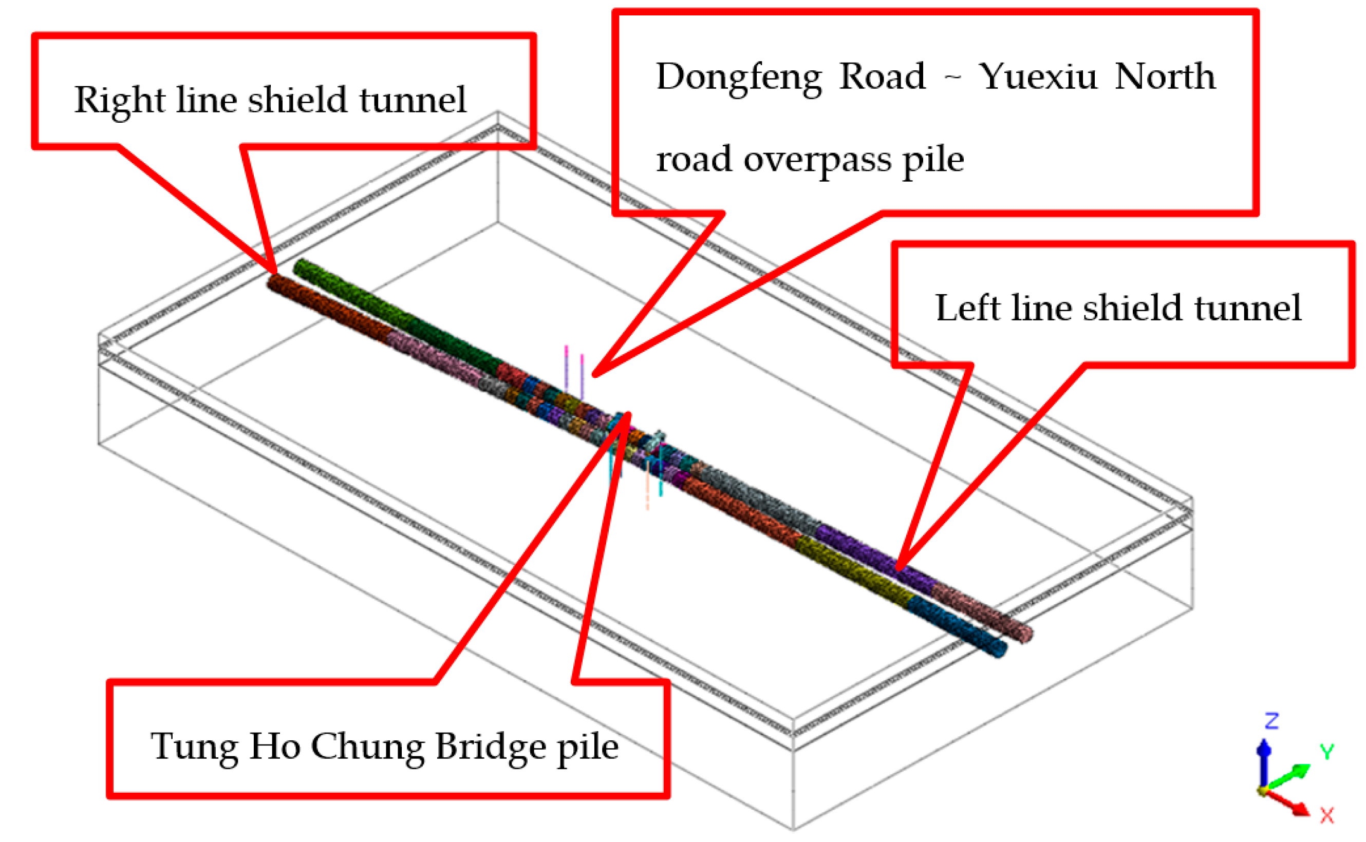
In the section between Cang and Jian, there is a range of approximately 130 m where the horizontal clear distance between the left and right line tunnels is less than 3 m. The right line passes by the underpinning piles of the ramp of the Donghaochong Elevated Bridge with small horizontal clear distances of 1.90 m and 0.99 m, respectively, and the left line passes by the bridge piles of the Dongfeng Road–Yuexiu North Road Overpass with small horizontal clear distances of 1.46 m and 1.02 m, respectively. During the shield tunneling process, there is a risk of deformation of the segment of the left line shield tunnel and the existing bridge piles. When passing through buildings (structures), shield construction will cause disturbance to the stratum, which may lead to the deformation of buildings (structures), affect the traffic, and even endanger the structural safety of the elevated bridge and pedestrian overpass. Ensuring the stability of the pile foundation during the shield tunneling process is a key point of the construction control of this project.
3. Construction Plan for Shield Tunneling with Small Clear Distance Through Existing Structures
3.1. Tunneling Scheme for Test Section
The Tunneling Parameters for the Trial Section Are Shown in
Table 1.
3.1.1. Shield Tunnel Attitude Control
Adjust the tunneling direction of the shield machine according to the tunnel axis and measurement positioning, and maintain a stable posture during tunneling. The adjustment amount for each ring’s posture should be within 5 mm, and the posture should be controlled within a range of plus or minus 50 mm. Based on the analysis of the shield machine’s posture since tunneling in the test section and the actual manual review of the posture, the posture is basically consistent.
3.1.2. Segment Type Selection and Assembly
Segment selection and installation must adhere to two principles: compatibility with the tunnel design alignment and adaptation to the shield machine’s orientation. The assembly process involves 16 predefined positions, determined by the on-duty engineer based on shield tail clearance and alignment requirements of the fitted tunnel profile. In the shield-driven section, segments are installed using an interlocking staggered joint method. Installation begins with the bottommost segment, followed by the immediate connection of longitudinal bolts. The remaining segments are then symmetrically positioned from bottom to top, alternating left and right, with both longitudinal and annular bolts connected and tightened progressively as each segment is placed. For the closure (key) segment, a three-step process is applied: partial engagement (1/3 length), radial insertion with positional adjustments, and slow longitudinal pushing. Upon full ring assembly, all bolts are tightened using pneumatic wrenches, and grouting hole plugs are securely fastened. Completion of these steps allows the shield machine to advance to the next excavation cycle.
3.1.3. Synchronous Grouting
Cement mortar is used as the synchronous grouting material, with P.O.42.5 ordinary Portland cement. The synchronous grouting adopts two-component grout. Based on previous construction experience and trial mixing in the laboratory, several different mix ratios are determined. During construction, different mix ratios are selected according to stratum conditions, groundwater conditions, surrounding conditions, etc., and the optimal mix ratio is determined through field tests, as shown in
Table 2.
The gelation time typically falls between 3 and 6 h. Depending on the stratum conditions and the tunneling speed, the gelation time can be adjusted by adding accelerators and altering the mixture ratio through on-site tests. For areas with highly permeable strata or those requiring relatively high early-stage strength, the mixture ratio can be further tweaked, or additives can be incorporated via field trials to further reduce the gelation time.
The pressure for synchronous grouting generally ranges from 1.1 to 1.2 times the sum of the static earth pressure and the static water pressure. The pressure for secondary reinforcing grouting is set at 0.1–0.3 MPa. The grouting volume is 1.3–1.8 times the theoretical volume of the annular gap, with the grouting volume per ring (Q) being 5.6–7.8 m3. The synchronous grouting speed should match the tunneling speed, and its average speed is determined based on completing the grouting volume for the current ring within the time it takes the shield machine to finish tunneling one ring. A dual-index control standard is adopted for grouting, meaning that the quality requirements are considered met when the grouting pressure reaches the set value and the grouting volume is over 90% of the designed volume.
3.1.4. The Synchronous Grouting Method
Synchronous grouting is conducted simultaneously with shield advancement through the grouting system and built-in grouting pipes at the shield tail, filling the annular void formed during excavation. The process employs dual-pump, four-pipeline (four injection points) symmetrical grouting. Grouting control operates in either automatic or manual mode: automatic mode presets the grouting pressure, with the control program adjusting the grouting rate until reaching the preset pressure threshold, then automatically stopping; manual mode allows real-time adjustment of the grouting flow, rate, and pressure based on excavation conditions.
3.1.5. Equipment Configuration
Design and build a mortar mixing station with a capacity of 14 m3/h on your own. Equip it with 4 hydraulic grouting pumps (already installed on the shield machine), with a grouting capacity of 4 × 12 m3/h, 8 grouting ports at the shield tail (4 of which are reserved), and their supporting pipelines. There are mortar tank trucks (7 m3) with self-mixing functions and mortar transfer pumps, which are transported along with the marshaling train.
3.1.6. Secondary Reinforcing Grouting
The secondary reinforcing grouting uses two-component grout, with ordinary Portland cement and water glass (concentration 40 Be) as materials. The volume ratio of cement slurry to water glass is 1:1. According to on-site mixing containers, the cement slurry mixing ratio is cement:water = 1:1.
The retarder dosage is 0–1.5% of cement content. The mixed slurry has a density of approximately 1.44 g/cm3, with initial setting time controlled at 20–48 s. Supplementary grouting is conducted through segment grouting holes using a KBY-50/70 two-component grouting pump. The grouting pressure is controlled at 0.3–0.6 MPa with a flow rate not exceeding 10 L/min. The grouting completion criterion is based solely on pressure control. The grouting volume is determined according to site conditions, while the grouting frequency is adjusted based on groundwater seepage and segment alignment monitoring.
3.1.7. Muck Removal Volume Management
In the test section, the muck removal volume per ring is controlled within 4.8 trucks (78 m3 loose volume). The duty engineer monitors the muck removal volume every 310 mm of tunneling progress and promptly reminds the chief driver to control the muck removal volume. Based on analysis of muck removal volumes for rings 1100 to 1200, the average muck removal volume in the test section was 78 m3, which did not exceed the design value.
3.2. Crossing Critical Structures
The left line of the Jiannong section passes laterally by the Medical Research Building of Sun Yat-sen University Cancer Center, which employs hand-dug piles with diameters of Φ1.0 m, Φ1.2 m, Φ1.3 m, and Φ1.8 m, and pile lengths of 7.6–25.8 m. The building is approximately 14.8 m horizontally from the shield tunnel. The Sun Yat-sen University Cancer Center utilizes 800 mm-thick diaphragm walls (height: 28.5 m), rock anchors (diameter: 0.15 m, length: 26–36 m), located 9.1 m horizontally and −0.9 m vertically from the tunnel. The Phase II five-story basement of the center employs bored piles (diameters: 0.7 m, 0.8 m, 0.9 m; lengths: 8–24 m), with the basement structure 2.2 m horizontally and 5.7 m vertically from the tunnel. Adjacent mined tunnels parallel the left-line shield tunnel over a long distance, with structural clearances of 2.4–8.7 m. The undercrossing zone primarily consists of highly weathered argillaceous siltstone, locally transitioning to slightly weathered argillaceous siltstone.
3.3. Shield Construction Measures for Small-Clearance Crossings
3.3.1. Survey Control
When the shield machine enters the protection zone, adjust tunneling parameters promptly based on monitoring data to ensure safe passage through structures. During the crossing phase, perform daily manual verification of shield machine alignment and segment positioning. Compare manual measurements with automatic guidance system data to identify and resolve discrepancies immediately. Determine tunneling mode through a comprehensive analysis of geological conditions, burial depth, and shield operation parameters when passing beneath structures.
The tunnel section primarily traverses moderately weathered and slightly weathered argillaceous siltstone with good self-stability, though with minimal clearance from adjacent structures. Maintain appropriate earth pressure during excavation while retaining suitable muck volume in the chamber. Based on real-time monitoring data and excavated material analysis, ensure earth pressure in the excavation chamber remains within specific parameters during undercrossing operations to guarantee smooth and stable tunneling beneath structures. Particular attention should be paid to coordinating pressure control with actual muck discharge quantities to achieve an optimal balance between ground settlement prevention and construction efficiency.
3.3.2. Muck Discharge Control
Strictly limit muck discharge to ≤78.8 m3 per ring.
3.3.3. Grouting Control
During the undercrossing of structures, synchronous grouting must be timely coordinated. Based on empirical formulas, the grouting volume is set at 1.3–1.8 times the theoretical annular gap volume, resulting in a grouting quantity of Q = 5.2–7.6 m3 per ring. Considering stratum permeability, a higher coefficient is adopted, with the actual grouting volume taken as 1.5 times the theoretical value (≥6.5 m3/ring). Based on shield construction experience, parameters are optimized through field trials according to geological conditions, groundwater status, and surrounding environments. The grout’s key physico-mechanical properties must meet specified criteria.
Synchronous grouting must strictly adhere to the principle of “simultaneous excavation and grouting; no grouting, no advancement,” implementing dual control of grouting pressure and volume to ensure adequacy and timeliness. Specific grouting parameters are further refined through real-time feedback from ground and stratum settlement monitoring.
During shield crossing of structures, secondary grouting using cement-sodium silicate grout is implemented as needed. Grouting locations, quantities, and pressures are executed in strict compliance with the undercrossing technical directive.
3.3.4. Alignment Control
Strictly manage shield deviation correction. Maintain rigorous control over shield machine alignment during tunneling, minimizing per-ring correction amplitude to ensure it does not exceed 9 mm. Based on measurement results from each ring and clearance conditions around the segments, provide precise guidance for the advancement of the next ring. Adjust jack extension lengths in each zone promptly to correct minor deviations at their initial stage. This approach prevents “snake-like” shield movement, reduces ground disturbance, and creates optimal conditions for segment assembly.
3.3.5. Segment Anti-Floating Measures
To prevent tunnel segment flotation, the following measures shall be implemented: master geological conditions including stratum strength, depth, moisture content, and soil distribution along the tunnel alignment, adopting differentiated tunneling methods based on geological characteristics; strictly control shield attitude to minimize deviation from the tunnel axis; rigorously execute precision measurement and control with appropriate verification frequency; employ optimized grouting methods and materials for anti-floating synchronous grouting; and select grout with appropriate performance parameters. For floated segments, immediately conduct secondary grouting using dual-component grout, prioritizing injection at tunnel haunches followed by the invert.
3.4. Additional Measures for Under-Crossing Structures
Increase monitoring frequency to 4 h intervals during under-crossing. Adjust earth pressure in real-time based on pile–tunnel positional relationships during advancement, maintaining appropriate muck accumulation in the chamber. Conduct specialized equipment inspections pre-crossing, dynamically adjust parameters per excavation conditions, and provide immediate feedback on anomalies. Ensure synchronous grouting volume reaches 6.5 m3, strictly meeting single-index grouting requirements.
Further intensify monitoring: 4 h intervals within pre-crossing influence zones, 2 h intervals during direct crossing. Maintain 1/2 chamber muck volume while real-time adjusting earth pressure. Implement equipment inspections and conduct technical/safety training. Enforce strict compliance with 6.5 m3/ring grouting volume. During crossing, perform secondary tracking grouting for insufficient segment backfill. Prepare for secondary and sleeve valve pipe grouting both underground and surface level. Replace worn components promptly through dedicated equipment inspections.
6. Conclusions
This paper summarizes a safety-specific construction scheme for horizontal small-clearance shield tunneling, reducing overall deformation through grouting reinforcement. Midas GTS(2022R1) finite element software was used to simulate the construction process, analyze grouting effectiveness, and evaluate the scheme via field monitoring. Key conclusions include the following:
The “tunnel-first, station-later” construction method meets horizontal small-clearance shield tunneling requirements, with impacts on existing bridge piles and pre-constructed tunnels within acceptable limits.
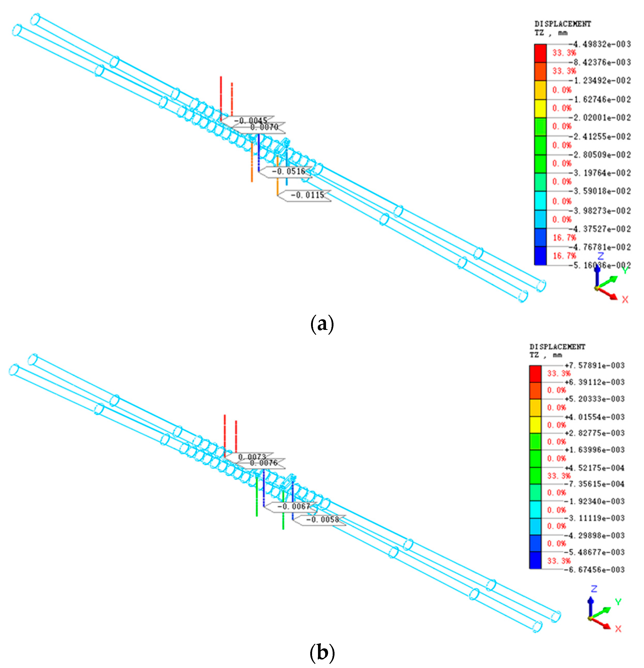
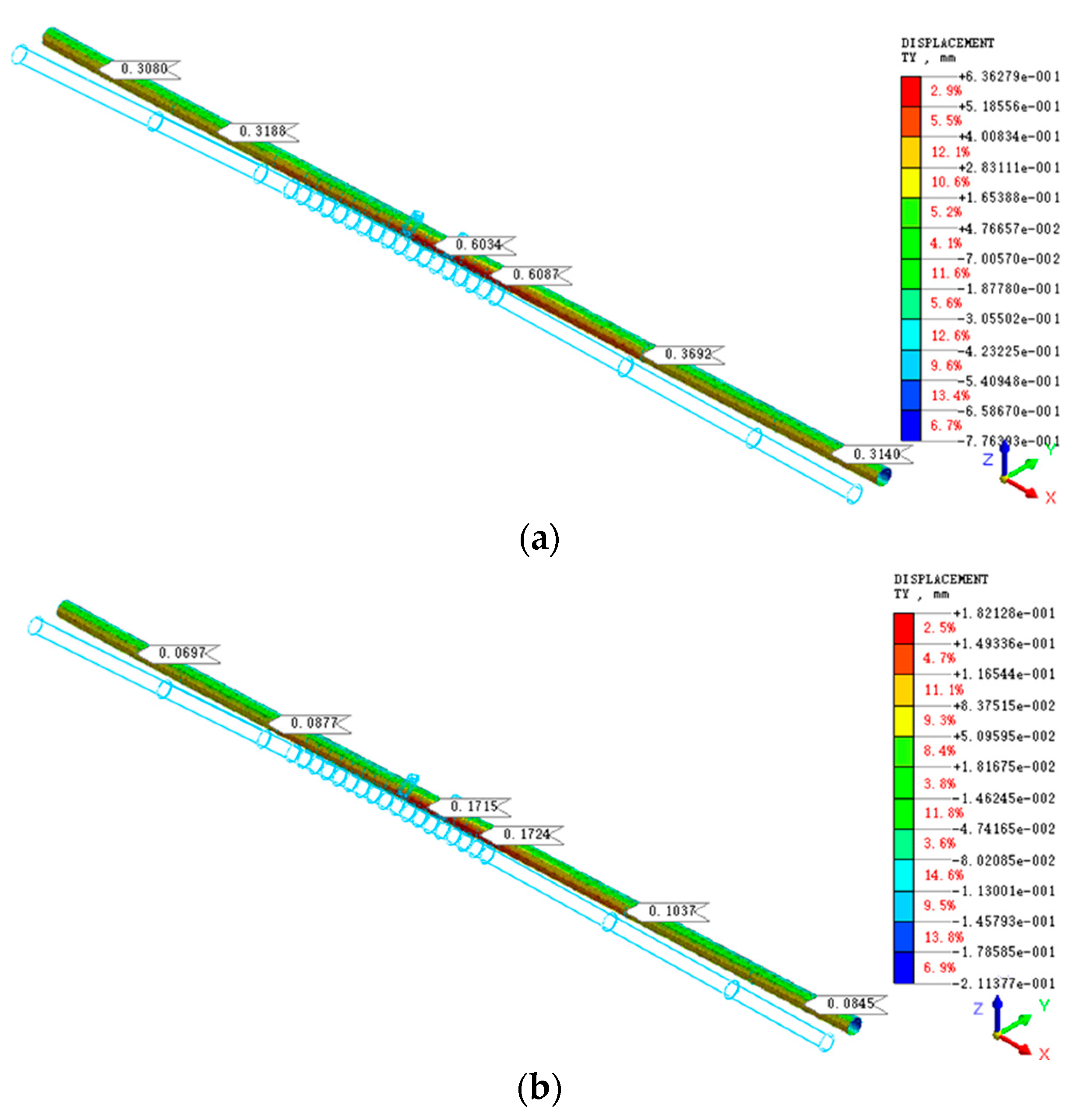
Grouting reinforcement effectively controls horizontal deformation of existing bridge piles (67.7% reduction) and left-line segments in small-clearance sections (72.1% reduction) compared to non-reinforced conditions.
Field monitoring confirms segment deformations comply with code requirements and bridge pile settlements do not compromise safety or normal operations.
This study explores the feasibility of the “tunnel-first, station-later” method for horizontal small-clearance shield tunneling, providing practical engineering references through numerical simulation and field validation.
Grouting reinforcement increases the shear strength and elastic modulus of the surrounding soil (see
Table 3, grouting E = 3000 MPa vs. silty clay E = 10 MPa), reducing soil displacement during shield excavation. This minimizes lateral earth pressure on bridge piles, particularly critical for piles with small clear distances (1.02–1.90 m), where soil–structure interaction is amplified. As shown in
Figure 5, grouting reduces pile horizontal deformation by 67.7% by constraining the plastic flow of weathered argillaceous siltstone, a stratum prone to softening under tunneling disturbance.


