
Development of a Solar-Tracking Movable Louver with a PV Module for Building Energy Reduction


Abstract
1. Introduction
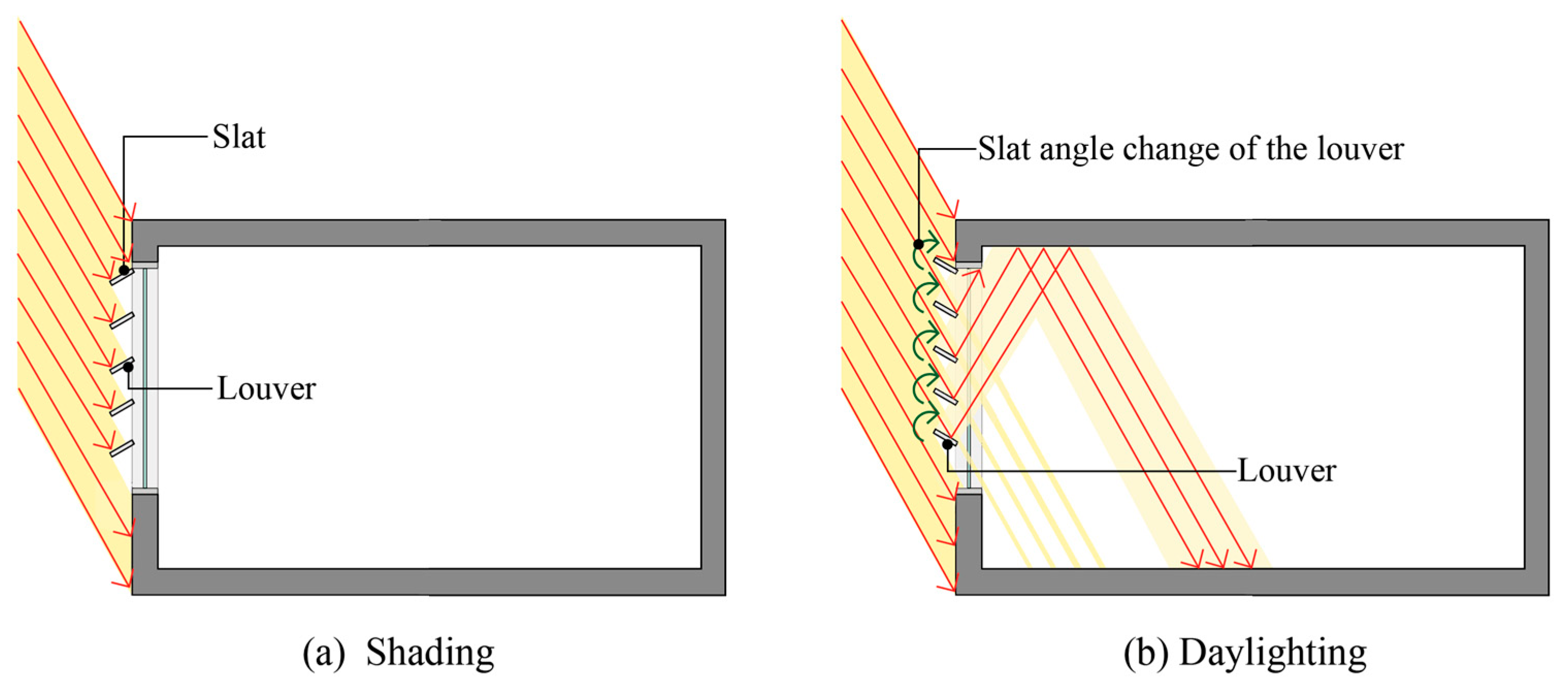
1.1. Types of Louvers and Literature Review
1.2. PV Module Concept
1.3. Concept of Solar-Tracking Technology
2. Materials and Methods
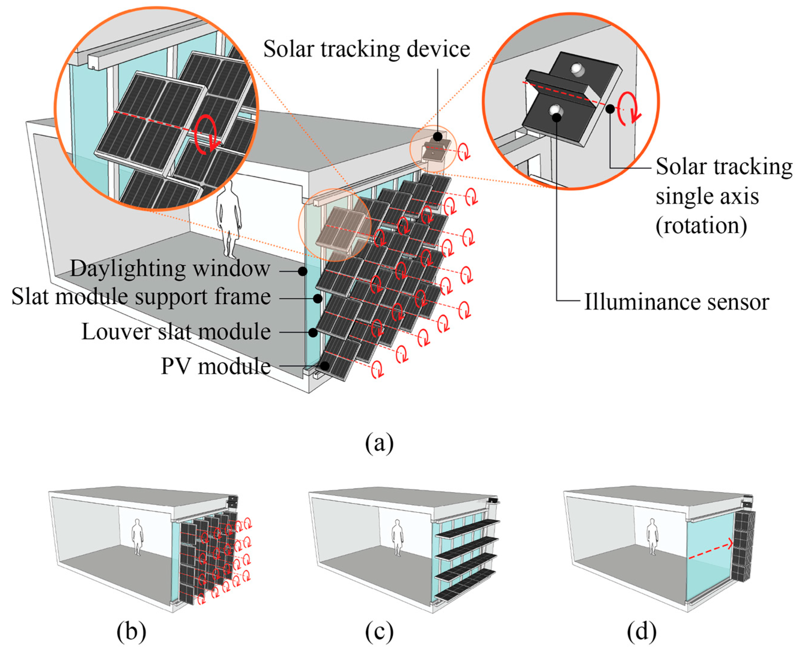
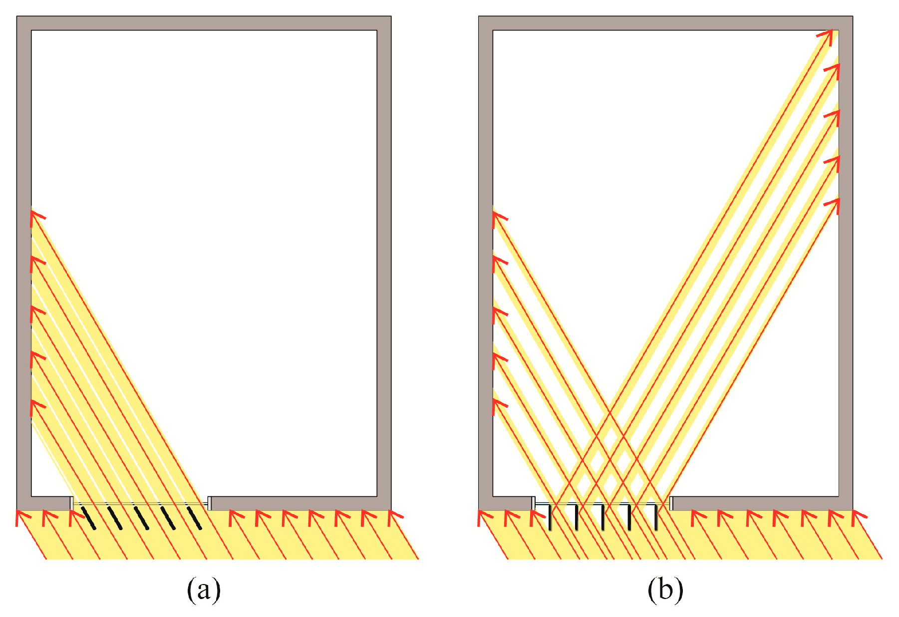
2.1. Design Suggestion for a PV-Integrated Movable Louver System Utilizing Solar-Tracking Technology
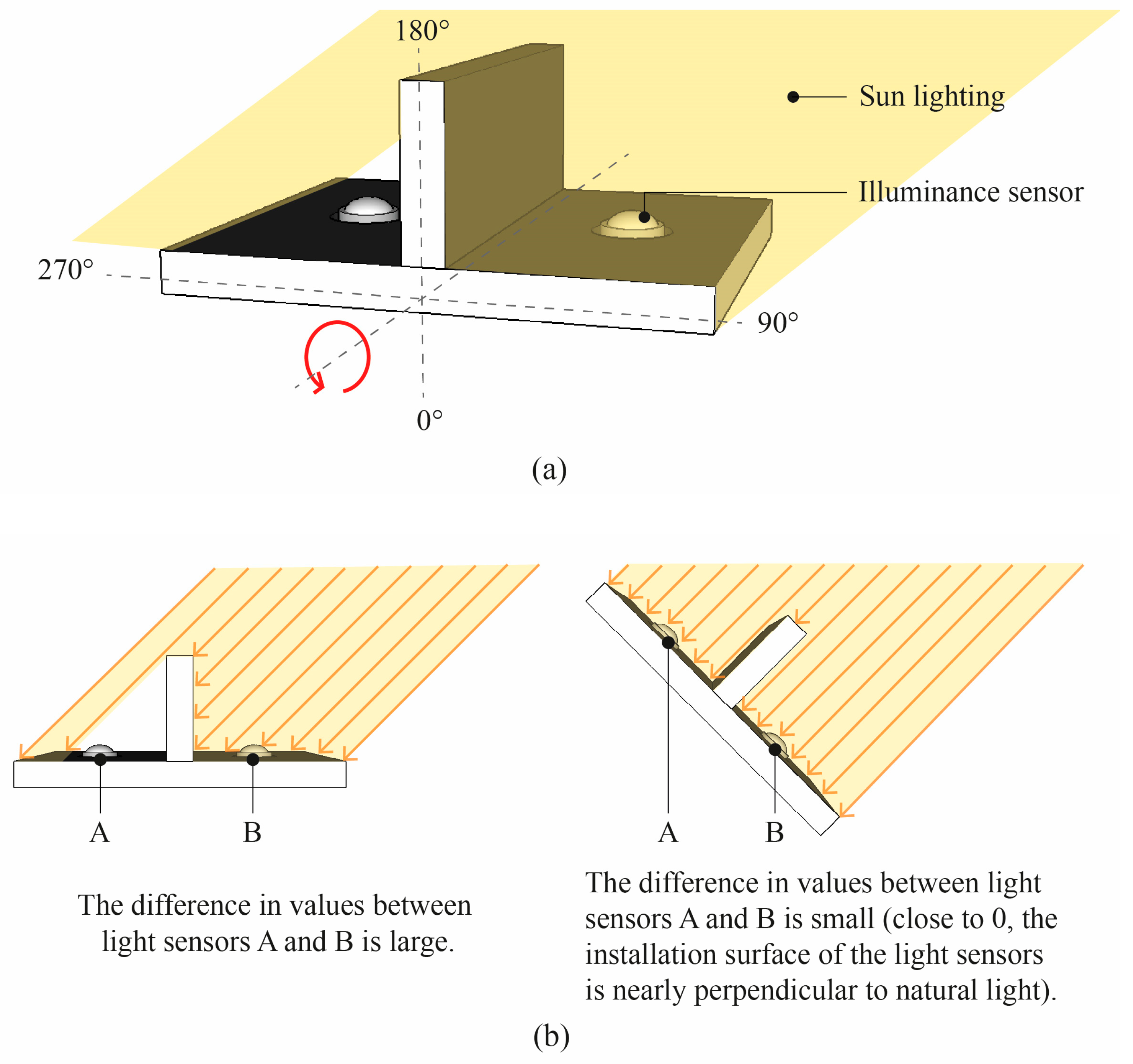
2.2. Performance Evaluation Environment Setup
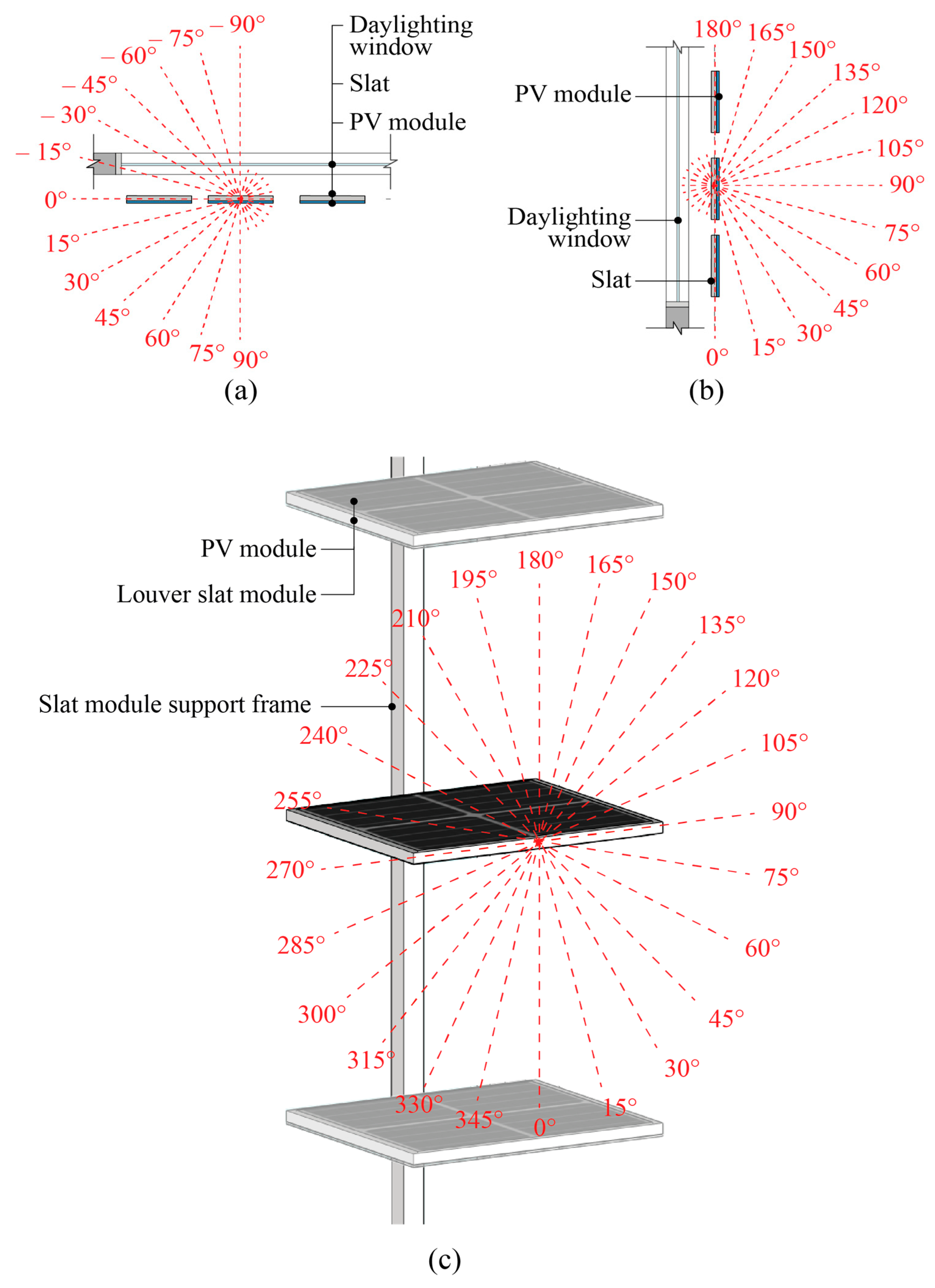
2.3. Performance Evaluation Method
3. Results and Discussion
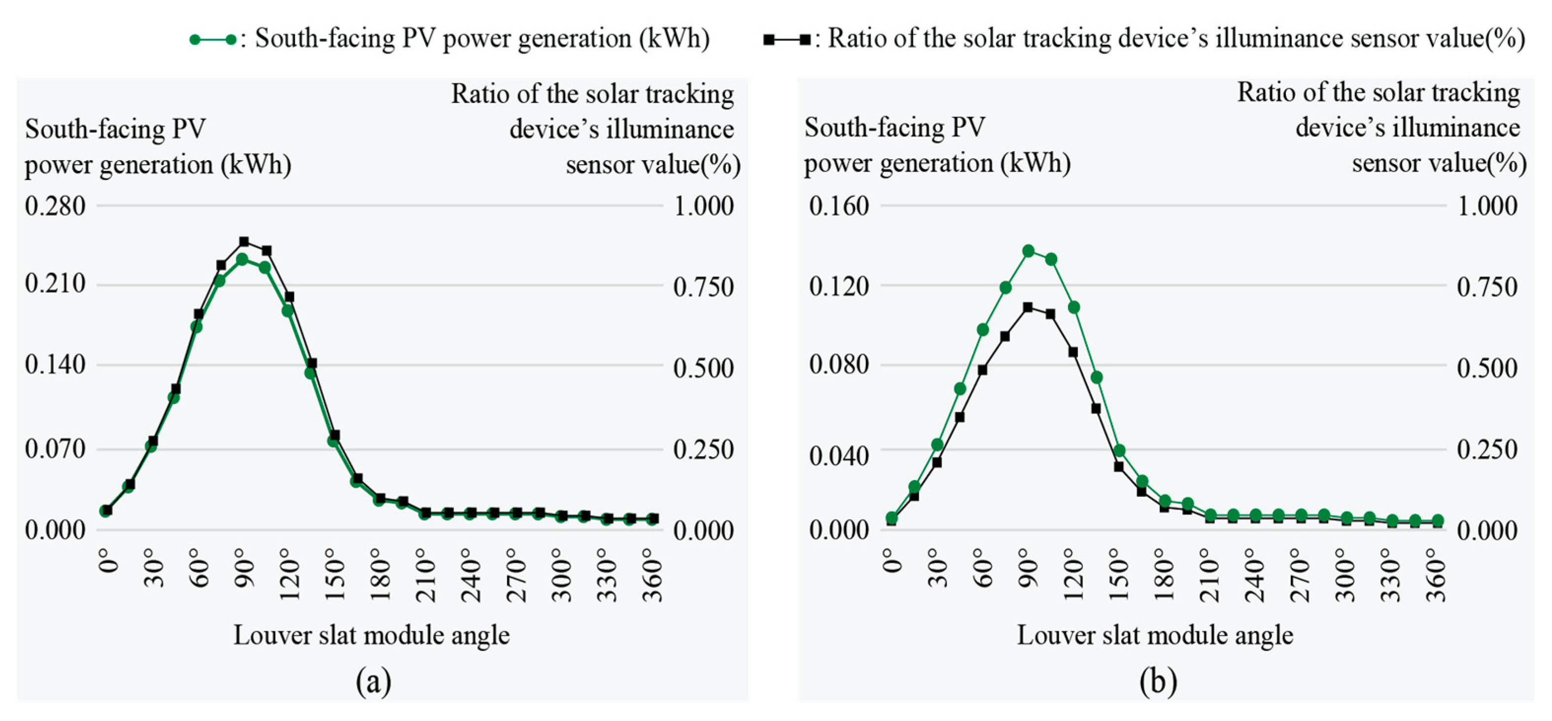
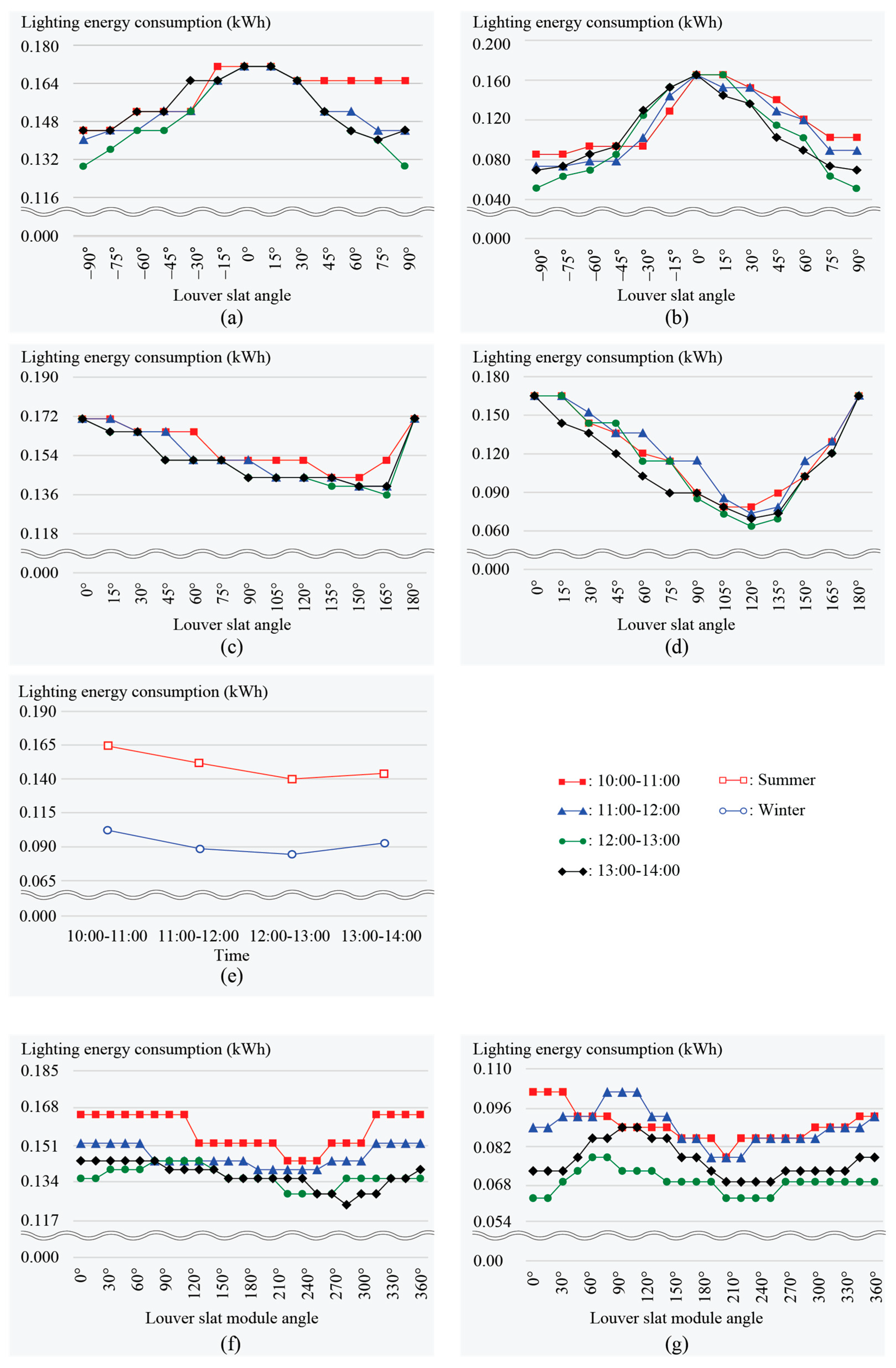
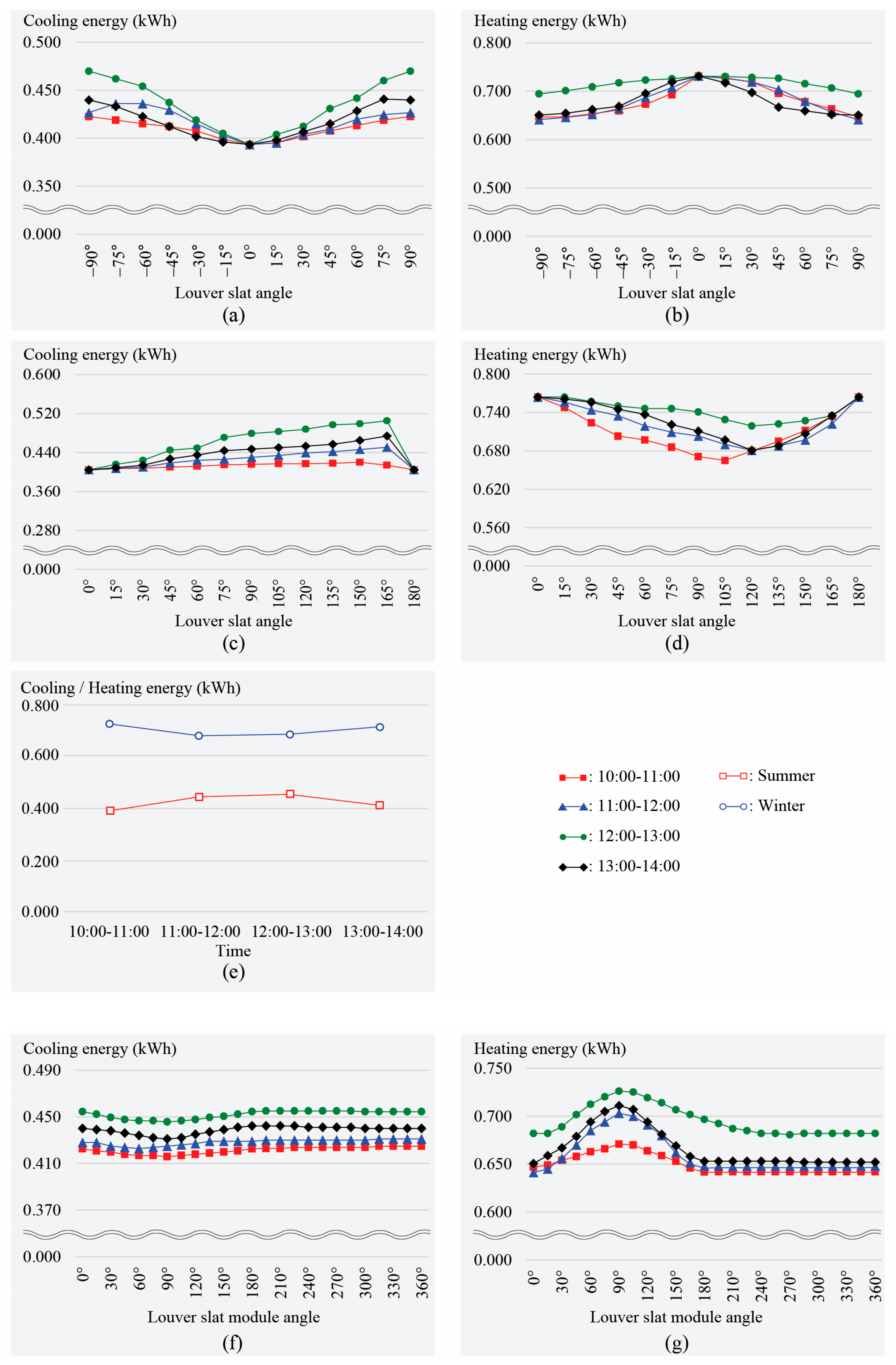
3.1. Performance Evaluation Results
3.2. Discussion
4. Conclusions
Author Contributions
Funding
Data Availability Statement
Conflicts of Interest
References
- Grobal Energy Trends 2023. Available online: https://www.enerdata.co.kr/publications/reports-presentations/world-energy-trends.html (accessed on 15 June 2023).
- Barea, G.; Victoria Mercado, M.; Filippín, C.; Monteoliva, J.M.; Villalba, A. New paradigms in bioclimatic design toward climatic change in arid environments. Energy Build. 2022, 266, 100–112. [Google Scholar] [CrossRef]
- Amasyali, K.; El-Gohary, N.M. A review of data-driven building energy consumption prediction studies. Renew. Sustain. Energ. Rev. 2018, 81, 1192–1205. [Google Scholar] [CrossRef]
- Uddin, M.; Ruva, I.; Syed, M.; Hossain, D.; Akter, R.; Tamanna, N.; Rahman, A.; Saka, A. Occupant centric energy renovation strategy for hospital and restaurant building envelop using distinct modelling tools: A case study from low income cultural context. Energy Build. 2022, 272, 112–338. [Google Scholar] [CrossRef]
- Wang, Y.; Dong, Q.; Guo, H.; Yin, L.; Gao, W.; Yao, W.; Sun, L. Indoor thermal comfort evaluation of traditional dwellings in cold region of china: A case study in Guangfu ancient city. Energy Build. 2023, 288, 113–128. [Google Scholar] [CrossRef]
- Gupta, G.; Mathur, S.; Mathur, J.; Nayak, B.K. Comparison of energy-efficiency benchmarking methodologies for residential buildings. Energy Build. 2023, 285, 112–920. [Google Scholar] [CrossRef]
- 2022 Global Status Report for Buildings and Construction. Available online: https://www.unep.org/resources/publication/2022-global-status-report-buildings-and-construction (accessed on 9 November 2022).
- Moazzeni, M.H.; Ghiabaklou, Z. Investigating the influence of light shelf geometry parameters on daylight performance and visual comfort, a case study of educational space in Tehran, Iran. Buildings 2016, 6, 26. [Google Scholar] [CrossRef]
- Soliman, M.E.; Bo, S. An innovative multifunctional biomimetic adaptive building envelope based on a novel integrated methodology of merging biological mechanisms. J. Build. Eng. 2023, 76, 106995. [Google Scholar] [CrossRef]
- Han, S.; Lee, M.; Lee, H. Effectiveness of internal light shelves to improve daylighting. Build. Simul. 2025, 18, 747–763. [Google Scholar] [CrossRef]
- Kim, J.; Ko, W.; Kim, J.; Byun, J.; Nam, S.; Jeong, S. Analyzing the environmental impacts and empirical limitations of green remodeling with life cycle assessment. Buildings 2025, 15, 783. [Google Scholar] [CrossRef]
- Jaradat, H.; Alshboul, O.A.M.; Obeidat, I.M.; Zoubi, M.K. Green building, carbon emission, and environmental sustainability of construction industry in Jordan: Awareness, actions and barriers. Ain Shams Eng. J. 2024, 15, 102–441. [Google Scholar] [CrossRef]
- Qiang, G.; Tang, S.; Hao, J.; Di Sarno, L.; Wu, G.; Ren, S. Building automation systems for energy and comfort management in green buildings: A critical review and future directions. Renew. Sust. Energ. 2023, 179, 113–301. [Google Scholar] [CrossRef]
- Xu, J.; Sun, J.; Zhao, J.; Zhang, W.; Zhou, J.; Xu, L.; Guo, H.; Liu, Y.; Zhang, D. Eco-friendly wood plastic composites with biomass-activated carbon-based form-stable phase change material for building energy conversion. Ind. Crops Prod. 2023, 197, 116–573. [Google Scholar] [CrossRef]
- Amin, M.S.; Heikal, M.; Negm, H.H.; Abu-Dief, A.M.; Mohamed, O.A. Manufacture of eco-friendly cementitious building materials of high performance from Egyptian industrial solid wastes. Constr. Build. Mater. 2023, 406, 133–446. [Google Scholar] [CrossRef]
- Sierra-Pérez, J.; López-Forniés, I.; Boschmonart-Rives, J.; Gabarrell, X. Introducing eco-ideation and creativity techniques to increase and diversify the applications of eco-materials: The case of cork in the building sector. J. Clean. Prod. 2016, 137, 606–616. [Google Scholar] [CrossRef]
- Hammad, F.; Abu-Hijleh, B. The energy savings potential of using dynamic external louvers in an office building. Energy Build. 2010, 42, 1888–1895. [Google Scholar] [CrossRef]
- Saelens, D.; Parys, W.; Roofthooft, J.; de la Torre, A.T. Assessment of approaches for modeling louver shading devices in building energy simulation programs. Energy Build. 2013, 60, 286–297. [Google Scholar] [CrossRef]
- Jung, S.K.; Kim, Y.; Moon, J.W. Performance evaluation of control methods for PV-integrated shading devices. Energies 2020, 13, 3171. [Google Scholar] [CrossRef]
- Yi, H.; Kim, Y. Prototyping of 4D-printed self-shaping building skin in architecture: Design, fabrication, and investigation of a two-way shape memory composite (TWSMC) façade panel. J. Build. Eng. 2021, 43, 103–176. [Google Scholar] [CrossRef]
- Reichert, S.; Menges, A.; Correa, D. Meteorosensitive architecture: Biomimetic building skins based onmaterially embedded and hygroscopically enabled responsiveness. Comput. Aid. Des. 2015, 60, 50–69. [Google Scholar] [CrossRef]
- Iqbal, W.; Ullah, I.; Hussain, A.; Cho, M.; Park, J.; Lee, K.; Shin, S. Optimizing energy efficiency: Louver systems for sustainable building design. Buildings 2025, 15, 1183. [Google Scholar] [CrossRef]
- Tao, S.; Yu, N.; Jiang, F.; Su, X.; Zhao, K. Correlations for forced convective heat transfer coefficients at the windward building façade with vertical louvers. Build. Environ. 2023, 242, 110–611. [Google Scholar] [CrossRef]
- Luo, Z.; Sun, C.; Dong, Q.; Qi, X. Key control variables affecting interior visual comfort for automated louver control in open-plan office—A study using machine learning. Build. Environ. 2022, 207, 108–565. [Google Scholar] [CrossRef]
- Pourshab, N.; Tehrani, M.D.; Toghraie, D.; Rostami, S. Application of double glazed façades with horizontal and vertical louvers to increase natural air flow in office buildings. Energy 2020, 200, 117–486. [Google Scholar] [CrossRef]
- Rafati, N.; Hazbei, M.; Eicker, U. Louver configuration comparison in three Canadian cities utilizing NSGA-II. Build. Environ. 2023, 229, 109–939. [Google Scholar] [CrossRef]
- Kangazian, A.; Emadian Razavi, S.Z. Multi-criteria evaluation of daylight control systems of office buildings considering daylighting, glare and energy consumption. Sol. Energy 2023, 263, 111–928. [Google Scholar] [CrossRef]
- Palmero-Marrero, A.I.; Oliveira, A.C. Effect of louver shading devices on building energy requirements. Appl. Energy 2010, 87, 2040–2049. [Google Scholar] [CrossRef]
- Luca, F.; Varjas, A. Multi-performance optimization of static shading devices for glare, daylight, view and energy consideration. Build. Environ. 2022, 217, 109–110. [Google Scholar] [CrossRef]
- Fang, J.; Zhao, Y.; Tian, Z.; Lin, P. Analysis of dynamic louver control with prism redirecting fenestrations for office daylighting optimization. Energy Build. 2022, 262, 112–119. [Google Scholar] [CrossRef]
- Alhuwayil, W.K.; Almaziad, F.A.; Abdul Mujeebu, M. Energy performance of passive shading and thermal insulation in multistory hotel building under different outdoor climates and geographic locations. Case Stud. Therm. Eng. 2023, 45, 102–940. [Google Scholar] [CrossRef]
- Mandalaki, M.; Tsoutsos, T.; Papamanolis, N. Integrated PV in shading systems for Mediterranean countries: Balance between energy production and visual comfort. Energy Build. 2014, 77, 445–456. [Google Scholar] [CrossRef]
- Peng, J.; Lu, L.; Yang, H. An experimental study of the thermal performance of a novel photovoltaic double-skin facade in Hong Kong. Sol. Energy 2013, 97, 293–304. [Google Scholar] [CrossRef]
- Chow, T.T.; Pei, G.; Chan, L.S.; Lin, Z.; Fong, K.F. A comparative study of PV glazing performance in warm climate. Indoor Built Environ. 2009, 18, 32–40. [Google Scholar] [CrossRef]
- Kim, J.J.; Jung, S.; Choi, Y.; Kim, J. Optimization of photovoltaic integrated shading devices. Indoor Built Environ. 2010, 19, 114–122. [Google Scholar] [CrossRef]
- Kim, M.; Kim, B.; Koh, J.; Yi, H. Flexural biomimetic responsive building façade using a hybrid soft robot actuator and fabric membrane. Autom. Constr. 2023, 145, 104–660. [Google Scholar] [CrossRef]
- Abdel-Rahman, W.S.M. Thermal performance optimization of parametric building envelopebased on bio-mimetic inspiration. Ain Shams Eng. J. 2021, 12, 1133–1142. [Google Scholar] [CrossRef]
- Alimi, O.A.; Meyer, E.L.; Olayiwola, O.I. Solar photovoltaic modules’ performance reliability and degradation analysis—A review. Energies 2022, 15, 5964. [Google Scholar] [CrossRef]
- Li, Z.; Ji, J.; Yuan, W.; Zhao, B.; Zhou, F.; Muin Uddin, M.; Ren, X.; Yu, B.; Song, Z. Experimental & numerical investigation and optimization on a novel flat-plate PV/T system using CdfTe thin-film solar modules of sandwich structure. Sol. Energy 2021, 223, 261–277. [Google Scholar] [CrossRef]
- Han, S.; Lee, H. Evaluation of energy performance and daylight utilization in light shelves integrated with transparent solar panels. Energy 2025, 326, 136336. [Google Scholar] [CrossRef]
- Huld, T.; Amillo, A.M. Estimating PV module performance over large geographical regions: The role of irradiance, air temperature, wind speed and solar spectrum. Energies 2015, 8, 5159–5181. [Google Scholar] [CrossRef]
- Lu, Y.; Li, G. Potential application of electrical performance enhancement methods in PV/T module. Energy 2023, 281, 128–253. [Google Scholar] [CrossRef]
- Han, S.; Seo, J.; Lee, H. Verification of the effectiveness of transparent photovoltaics according to the transmittance level in Seoul, South Korea. Sol. Energy 2025, 294, 113511. [Google Scholar] [CrossRef]
- Hu, Y.; Shen, H.; Yao, Y. A novel sun-tracking and target-aiming method to improve the concentration efficiency of solar central receiver systems. Renew. Energ. 2018, 120, 98–113. [Google Scholar] [CrossRef]
- Lu, J.; Hajimirza, S. Optimizing sun-tracking angle for higher irradiance collection of PV panels using a particle-based dust accumulation model with gravity effect. Sol. Energy 2017, 158, 71–82. [Google Scholar] [CrossRef]
- Fazal, M.A.; Rubaiee, S. Progress of PV cell technology: Feasibility of building materials, cost, performance, and stability. Sol. Energy 2023, 258, 203–219. [Google Scholar] [CrossRef]
- Pirayawaraporn, A.; Sappaniran, S.; Nooraksa, S.; Prommai, C.; Chindakham, N.; Jamroen, C. Innovative sensorless dual-axis solar tracking system using particle filter. Appl. Energy 2023, 338, 120–946. [Google Scholar] [CrossRef]
- Hafez, A.Z.; Yousef, A.M.; Harag, N.M. Solar tracking systems: Technologies and trackers drive types—A review. Renew. Sustain. Energ. Rev. 2018, 91, 754–782. [Google Scholar] [CrossRef]
- Carballo, J.A.; Bonilla, J.; Roca, L.; Berenguel, M. New low-cost solar tracking system based on open source hardware for educational purposes. Sol. Energy 2018, 174, 826–836. [Google Scholar] [CrossRef]
- Boukdir, Y.; Omari, H. Novel high precision low-cost dual axis sun tracker based on three light sensors. Heliyon 2022, 8, e12412. [Google Scholar] [CrossRef]
- Mamodiya, U.; Tiwari, N. Dual-axis solar tracking system with different control strategies for improved energy efficiency. Comput. Electr. Eng. 2023, 111, 109–920. [Google Scholar] [CrossRef]
- Achkari, O.; El Fadar, A.; Amlal, I.; Haddi, A.; Hamidoun, M.; Hamdoune, S. A new sun-tracking approach for energy saving. Renew. Energ. 2021, 169, 820–835. [Google Scholar] [CrossRef]
- Mpodi, E.K.; Tjiparuro, Z.; Matsebe, O. Review of dual axis solar tracking and development of its functional model. Procedia Manuf. 2019, 35, 580–588. [Google Scholar] [CrossRef]
- Zhu, Y.; Liu, J.; Yang, X. Design and performance analysis of a solar tracking system with a novel single-axis tracking structure to maximize energy collection. Appl. Energy 2020, 264, 114–647. [Google Scholar] [CrossRef]
- Saymbetov, A.; Mekhilef, S.; Kuttybay, N.; Nurgaliyev, M.; Tukymbekov, D.; Meiirkhanov, A.; Dosymbetova, G.; Svanbayev, Y. Dual-axis schedule tracker with an adaptive algorithm for a strong scattering of sunbeam. Sol. Energy 2021, 224, 285–297. [Google Scholar] [CrossRef]
- Alomar, O.R.; Ali, O.M.; Ali, B.M.; Qader, V.S.; Ali, O.M. Energy, exergy, economical and environmental analysis of photovoltaic solar panel for fixed, single and dual axis tracking systems: An experimental and theoretical study. Case Stud. Therm. Eng. 2023, 51, 103–635. [Google Scholar] [CrossRef]
- Awasthi, A.; Shukla, A.K.; Murali Manohar, S.R.; Dondariya, C.; Shukla, K.N.; Porwal, D.; Richhariya, G. Review on sun tracking technology in solar PV system. Energy Rep. 2020, 6, 392–405. [Google Scholar] [CrossRef]
- Illuminating Engineering Society. The Lighting Handbook, 10th ed.; Illuminating Engineering Society (IES): New York, NY, USA, 2011. [Google Scholar]
- Zhao, X.; Seo, J.; Lee, H. Performance evaluation of a light shelf with a folding reflector (LSFR) to improve daylighting performance. Build. Environ. 2024, 255, 111457. [Google Scholar] [CrossRef]
- Lee, H.; Kim, S.; Seo, J. Evaluation of a light shelf based on energy consumption for lighting and air conditioning. Indoor Built Environ. 2018, 27, 1405–1414. [Google Scholar] [CrossRef]
- Korea Meteorological Administration. Available online: https://www.kma.go.kr/eng/weather/climate/worldclimate.jsp (accessed on 8 June 2025).


| Type | Characteristics | Best Orientation | Image | |
|---|---|---|---|---|
| Horizontal | Overhang | -Prevents the rise of hot air from outside -Potential risk of damage due to wind pressure and snow accumulation | South | 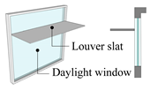 |
| Overhang with Multiple Blades | -Installed in the form of multiple horizontal slats -Potential risk of damage due to wind pressure and snow accumulation | South | 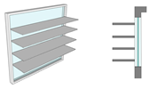 | |
| Overhang Horizontal Louvers | -Horizontal slats divided into uniform sizes -Allows free movement of air -Low snow and wind load | South |  | |
| Overhang Vertical Panel | -Allows free movement of air -Low risk of damage due to snowfall -Causes visual obstruction | South, East, West | 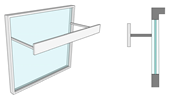 | |
| Vertical | Vertical Fin | -Typically used only in hot climates for north-facing windows -May obstruct visibility | East, West | 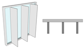 |
| Slanted Vertical Fin | -Installed at an angle (not perpendicular) to the window -May obstruct visibility | East, West |  | |
| Mixed | Eggcrate | -Used in very hot climates -Tends to trap hot air -Causes high visual obstruction | East, West |  |
| Eggcrate with Horizontal Louvers | -Applies horizontal slats in the form of overhang horizontal louvers -Partially mitigates the trapping of hot air -Suitable for use in very hot climates -Causes high visual obstruction | East, West | 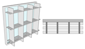 | |
| Reference | Objective | Louver | PV Application | Use of Solar-Tracking Technology | ||
|---|---|---|---|---|---|---|
| Type (Shape) | Width (m) | Angle | ||||
| [19] | Developed optimal control for BIPV to improve energy efficiency and visual comfort | Horizontal | - | −78° to 78° | Applied (PV attached to only half of the slats) | Not applied |
| [20] | Developed three prototype adaptive facade systems compatible with curvature by applying biomimicry and SMC | A shape that mimics the curvature of a fabric membrane | - | Changes by 20° | Not applied | Not applied |
| [21] | Presented a responsive envelope using hygroscopic material properties | A form that mimics the shape and function of cactus stomata | - | It closes at 50% relative humidity and opens at 85% | Not applied | Not applied |
| [32] | Evaluated fixed shading systems with integrated solar power generation in Mediterranean countries | Horizontal | - | - | Applied (Attached to the top surface) | Not applied |
| [33] | Developed a new ventilated BIPV double skin facade system consisting of transparent amorphous silicon PV modules and inward-opening windows | Horizontal | 1.1 | Fixed | Applied (Only to the external glass) | Not applied |
| [34] | Assessed translucent PV ventilated glazing for energy and cost savings | Horizontal | 0.88 | - | Applied (Attach translucent PV to the window) | Not applied |
| [35] | Tested prototype PV-integrated louver system for optimal shading, daylighting, and solar energy production | Horizontal | 0.41 | −90°, −60°, −30°, 0°, 30°, 60°, 90° | Applied (PV attached only to 2/3 of slats) | Not applied |
| [36] | Hybridized the physical characteristics of thermodynamic SMA springs and PFEA, which balance forces, to propose facade panel module designs | A form that mimics cactus surface | - | The length changes to 31.5, 50.7, and 68.1mm depending on the pressure | Not applied | Not applied |
| [37] | Designed building envelopes for improved thermal performance through a biomimetic optimization algorithm | A form that mimics the hygroscopic structure of a pine cone | - | Optimal rotation angle 43°, optimal enclosure angle 69° | Not applied | Not applied |
| Method | Characteristics | Image |
|---|---|---|
| Single-axis tracking method | -Pivots along a single axis responding to the sun’s azimuth or altitude (divided into vertical and horizontal tracking) -Tracks the sun’s movement from east to west based on its position -Stability and power generation efficiency can be improved with external support -Does not account for external factors such as weather and shading | 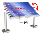 |
| Dual-axis tracking method | -Rotates around two perpendicular axes, simultaneously tracking solar azimuth and altitude angles -Produces energy at a faster rate than single-axis tracking systems -Tracks both the sun’s movement from east to west and its altitude -Less affected by clouds and other environmental conditions | 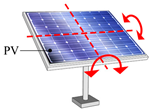 |
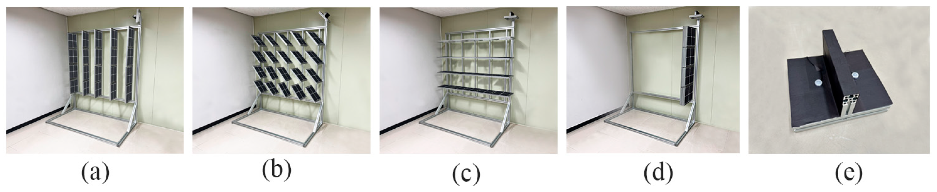
| Case | Image | Louver Type | Movable or Not | Slat | Slat module | PV Module Area (Number of PV Cells Used) | ||||
|---|---|---|---|---|---|---|---|---|---|---|
| Count | Size | Spacing | Angle | Size | Angle | |||||
| 1 |  | Vertical | Fixed | 5 | 0.03 m (W) × 0.35 m (D) × 1.65 m (H) | 0.375 m | Moves within a range of −90° to 90° in 15° increments | - | - | 2.43 m2 (100) |
| 2 |  | Horizontal | Fixed | 4 | 1.85 m (W) × 0.35 m (D) × 0.03 m (H) | 0.41 m | Moves within a range of 0° to 180° in 15° increments | - | - | 2.14 m2 (88) |
| 3 |  | Mixed | Fixed | 9 | Combination of Cases 1 and 2 | Vertical 0.37 m, horizontal 0.41 m | 0 | - | - | 5.84 m2 (240) |
| 4 |  | Vertical and horizontal | Movable | 5 | Each slat is divided into 4 modules | - | 0°, 90° | 0.03 m (W) × 0.31 m (D) × 0.38 m (H) | Moves within a range of 0° to 360° in 15° increments | 1.95 m2 (80) |
| Item | Specifications | Item | Specifications |
|---|---|---|---|
| Type | Monocrystalline Silicon | Open-Circuit Voltage | 0.678 V |
| Max. Power (Pmax) | 5.35 W | Fill Factor | 80.75% |
| Voltage at Max. Power Point (Vmpp) | 0.577 V | Size | 0.156 m × 0.156 m |
| Current at Max. Power Point | 9.329 A | Cell Efficiency | 21.9% |
| Specifications | Values | Specifications | Values |
|---|---|---|---|
| Model | ML-02 | Non-linearity at 1000 W/m2 | <0.2% |
| Wavelength range | 400~1100 nm | Directional response at 1000 W/m2 | <10 W/m2 |
| Response time 95% | <1 ms | Sensitivity (μV/W/m2) | Approx. 50 |
| Non-stability (change/year) | ±2% | Operating temperature range | –30 to +70 |
| Season | Temperature of the Artificial Climate Chamber | External Illuminance, Azimuth Angle, Solar Altitude, and Solar Radiation by Time Zone | |||
|---|---|---|---|---|---|
| 10:00–11:00 | 11:00–12:00 | 12:00–13:00 | 13:00–14:00 | ||
| Summer | 27.1 °C | 70 k lx, 120°, 60° 530 W/m2 | 75 k lx, 150°, 70° 574 W/m2 | 80 k lx, 180°, 76.5° 638 W/ m2 | 70 k lx, 203°, 70° 574 W/m2 |
| Winter | –3.2 °C | 20 k lx, 157°, 22.5° 289 W/m2 | 25 k lx, 172°, 28° 296 W/m2 | 30 k lx, 180°, 29.5° 332 W/m2 | 20 k lx, 187°, 26.5° 296 W/m2 |
| Case | Optimal Angle of the Slat Module for Improving Power Generation | Total Power Generation (kWh) | Power Generation per 1 m2 (kWh) | |||||||
|---|---|---|---|---|---|---|---|---|---|---|
| Summer | Winter | |||||||||
| 10:00–11:00 | 11:00–12:00 | 12:00–13:00 | 13:00–14:00 | 10:00–11:00 | 11:00–12:00 | 12:00–13:00 | 13:00–14:00 | |||
| 1 | 60° | 30° | 0° | –30° | 30° | 15° | 0° | 0° | 1.326 | 0.546 |
| 2 | 60° | 75° | 75° | 75° | 15° | 30° | 30° | 30° | 1.366 | 0.638 |
| 3 | - | - | - | - | - | - | - | - | 1.539 | 0.264 |
| 4 | 60° | 75° | 90° | 105° | 45° | 75° | 90° | 105° | 1.387 | 0.711 |
| Case | Optimal Angle of the Slat Module for Improving Power Generation | Total Lighting Energy Consumption (kWh) | |||||||
|---|---|---|---|---|---|---|---|---|---|
| Summer | Winter | ||||||||
| 10:00–11:00 | 11:00–12:00 | 12:00–13:00 | 13:00–14:00 | 10:00–11:00 | 11:00–12:00 | 12:00–13:00 | 13:00–14:00 | ||
| 1 | –90° | –90° | 90° | 75° | –90° | –90° | 90° | 90° | 0.831 |
| 2 | 150° | 165° | 165° | 165° | 105° | 120° | 120° | 120° | 0.843 |
| 3 | - | - | - | - | - | - | - | - | 0.970 |
| 4 | * 255° | 195° | 240° | 270° | 195° | 195° | 240° | 240° | 0.825 |
| ** 60° | 75° | 90° | 105° | 45° | 75° | 90° | 105° | 0.950 | |
| Case | Optimal Angle of the Slat Module for Energy Reduction | Total Summer Energy Usage (kWh) | Total Winter Energy Usage (kWh) | * Total Energy Usage (kWh) | |||||||
|---|---|---|---|---|---|---|---|---|---|---|---|
| Summer | Winter | ||||||||||
| 10:00–11:00 | 11:00–12:00 | 12:00–13:00 | 13:00–14:00 | 10:00–11:00 | 11:00–12:00 | 12:00–13:00 | 13:00–14:00 | ||||
| 1 | 60° | 30° | 0° | –30° | –30° | 90° | –90° | –90° | 1.424 | 2.844 | 4.268 |
| 2 | 60° | 75° | 60° | 75° | 105° | 120° | 60° | 120° | 1.493 | 2.965 | 4.458 |
| 3 | - | - | - | - | - | - | - | - | 1.431 | 2.889 | 4.320 |
| 4 | 60° | 75° | 90° | 105° | 45° | 75° | 90° | 105° | 1.425 | 2.642 | 4.067 |
| Case | Optimal Angle of the Slat Module to Improve the Total Heating and Cooling Energy Usage | Total Cooling Energy (kWh) | Total Heating Energy (kWh) | Total Heating and Cooling Energy (kWh) | |||||||
|---|---|---|---|---|---|---|---|---|---|---|---|
| Summer | Winter | ||||||||||
| 10:00–11:00 | 11:00–12:00 | 12:00–13:00 | 13:00–14:00 | 10:00–11:00 | 11:00–12:00 | 12:00–13:00 | 13:00–14:00 | ||||
| 1 | 0° | 0° | 0° | 0° | –45° | –90° (90°) | –90° (90°) | –90° (90°) | 1.574 | 2.643 | 4.217 |
| 2 | 0° (180°) | 0° (180°) | 0° (180°) | 0° (180°) | 105° | 120° | 120° | 120° | 1.619 | 2.746 | 4.365 |
| 3 | - | - | - | - | - | - | - | - | 1.787 | 3.077 | 4.864 |
| 4 | * 90° | 60° | 90° | 90° | 0° | 180° | 270° | 0° | 1.715 | 2.628 | 4.343 |
| ** 60° | 75° | 90° | 105° | 45° | 75° | 90° | 105° | 1.718 | 2.785 | 4.503 | |
| PV Module Power Generation (kWh) | Total Lighting Energy (kWh) | Total Heating Energy (kWh) | * Total Energy Usage (kWh) |
|---|---|---|---|
| 0.014 | 0.176 | 2.097 | 2.259 |
Disclaimer/Publisher’s Note: The statements, opinions and data contained in all publications are solely those of the individual author(s) and contributor(s) and not of MDPI and/or the editor(s). MDPI and/or the editor(s) disclaim responsibility for any injury to people or property resulting from any ideas, methods, instructions or products referred to in the content. |
© 2025 by the authors. Licensee MDPI, Basel, Switzerland. This article is an open access article distributed under the terms and conditions of the Creative Commons Attribution (CC BY) license (https://creativecommons.org/licenses/by/4.0/).
Share and Cite
Han, S.; Seo, J.; Lee, H. Development of a Solar-Tracking Movable Louver with a PV Module for Building Energy Reduction. Buildings 2025, 15, 2100. https://doi.org/10.3390/buildings15122100
Han S, Seo J, Lee H. Development of a Solar-Tracking Movable Louver with a PV Module for Building Energy Reduction. Buildings. 2025; 15(12):2100. https://doi.org/10.3390/buildings15122100
Chicago/Turabian StyleHan, Sowon, Janghoo Seo, and Heangwoo Lee. 2025. "Development of a Solar-Tracking Movable Louver with a PV Module for Building Energy Reduction" Buildings 15, no. 12: 2100. https://doi.org/10.3390/buildings15122100
APA StyleHan, S., Seo, J., & Lee, H. (2025). Development of a Solar-Tracking Movable Louver with a PV Module for Building Energy Reduction. Buildings, 15(12), 2100. https://doi.org/10.3390/buildings15122100