Article

Mechanical Properties of Large-Volume Waste Concrete Lumps Cemented by Desert Mortar: Laboratory Tests

1
School of Geological and Mining Engineering, Xinjiang University, Urumqi 830047, China
2
Collaborative Innovation Center for Green Development and Ecological Restoration of Mineral Resources in Xinjiang Province, Xinjiang University, Urumqi 830047, China
*
Author to whom correspondence should be addressed.
Buildings 2025, 15(12), 2060; https://doi.org/10.3390/buildings15122060
Submission received: 8 May 2025 / Revised: 4 June 2025 / Accepted: 12 June 2025 / Published: 15 June 2025

Abstract

In response to the high cost and environmental impact of backfill materials in Xinjiang mines, an eco-friendly, large-volume composite was developed by bonding desert-sand mortar to waste concrete. A rock-filled concrete process produced a highly flowable mortar from desert sand, cement, and fly ash. Waste concrete blocks served as coarse aggregate. Specimens were cured for 28 days, then subjected to uniaxial compression tests on a mining rock-mechanics system using water-to-binder ratios of 0.30, 0.35, and 0.40 and aggregate sizes of 30–40 mm, 40–50 mm, and 50–60 mm. Mechanical performance—failure modes, stress–strain response, and related properties—was systematically evaluated. Crack propagation was tracked via digital image correlation (DIC) and acoustic emission (AE) techniques. Failure patterns indicated that the pure-mortar specimens exhibited classic brittle fractures with through-going cracks. Aggregate-containing specimens showed mixed-mode failure, with cracks flowing around aggregates and secondary branches forming non-through-going damage networks. Optimization identified a 0.30 water-to-binder ratio (Groups 3 and 6) as optimal, yielding an average strength of 25 MPa. Among the aggregate sizes, 40–50 mm (Group 7) performed best, with 22.58 MPa. The AE data revealed a three-stage evolution—linear-elastic, nonlinear crack growth, and critical failure—with signal density positively correlating to fracture energy. DIC maps showed unidirectional energy release in pure-mortar specimens, whereas aggregate-containing specimens displayed chaotic energy patterns. This confirms that aggregates alter stress fields at crack tips and redirect energy-dissipation paths, shifting failure from single-crack propagation to a multi-scale damage network. These results provide a theoretical basis and technical support for the resource-efficient use of mining waste and advance green backfill technology, thereby contributing to the sustainable development of mining operations.

1. Introduction

The climate of Xinjiang is predominantly arid and semi-arid, characterized by severe water shortages and sparse vegetation, resulting in an extremely sensitive and vulnerable ecological environment [1]. This type of environment is particularly susceptible to disturbances from natural factors and human interventions, making it especially fragile. Under such conditions, untreated mined-out areas often lead to surface subsidence [2]. Thus, utilizing backfill mining technology to manage mined-out areas has become an essential task in the sustainable development of the mining industry. Backfill mining technology [3] occupies a central position in the mining sector and has extensive applications, playing a crucial role in promoting the industry’s sustainability. By filling the excavated voids with specific materials such as tailings, waste rock, or cementitious materials, this technique effectively controls ground pressure and prevents surface subsidence, protecting surface buildings and infrastructure from damage, thereby ensuring harmony between mining activities and the surface environment. Moreover, the application of this technology promotes the recycling and reuse of waste, converting tailings and waste rock into backfill materials, which not only reduces the environmental pollution, but also alleviates the challenges associated with mine waste disposal, thus embodying the principles of the circular economy [4,5,6]. Therefore, backfill mining technology represents not only a technological advancement in mining, but also an important pathway toward green mining practices, resource conservation, and environmental protection, significantly contributing to making mining safer, more environmentally friendly, and economically sustainable [7,8].
Currently, various types of materials are used for filling mined-out areas in underground mines, generally categorized into inert and cementitious backfill materials. Inert materials primarily include tailings, waste rock [9], limestone, and slag, which remain physically and chemically stable during the filling process, effectively serving as void fillers and structural support. However, these materials often have relatively large gaps and are susceptible to groundwater influences. Cementitious materials, including cement, high-water materials, fly ash, and gypsum, undergo curing reactions after filling to form structures with strength, effectively supporting the surrounding rock and preventing subsidence. However, these materials require large volumes per unit, incur higher costs, and often necessitate more complex construction techniques and equipment, including precise batching, mixing, pumping, and hydration reaction control, thus increasing operational difficulty and management expenses [10,11,12]. To establish an environmentally friendly resource environment, efforts are being devoted to exploring a new development model aimed at minimizing energy consumption and achieving the efficient utilization and conservation of resources.
In recent years, research on environmentally friendly cementitious materials has grown significantly, demonstrating promising applications for alternative materials such as polymers and slag in the construction and backfilling sectors [13,14]. For example, Wang Xiaoyong and Wang Zhaoming [15] conducted in-depth studies on cement-fly ash cemented gangue backfill materials. Their investigation into the rheological properties and consolidation mechanisms indicated that a properly proportioned slurry could effectively utilize solid waste from mining areas while satisfying the underground structural support requirements. Similarly, research by Jia Xueqiang and Feng Guorui [16] demonstrated that recycled fine aggregates from waste concrete could effectively replace the fine limestone aggregates commonly used in mines to prepare filling paste. This substitution not only enhanced the performance of the filling paste, but also promoted the recycling of construction waste. Additionally, research by X. Ding [17] revealed that CCFA significantly improved the long-term hydration properties of cement-based materials, with the optimal compressive strength achieved at a 10% admixture ratio, confirming the potential of CCFA as a supplementary cementitious material. Despite advancements in the resource utilization of industrial solid waste for mine backfilling, there remains a research gap concerning the combined use of desert sand and waste concrete specifically for arid regions. Existing studies have largely focused on optimizing the properties of single waste materials and have tended to overlook the coupled effects of the water-to-binder ratio, aggregate particle size, and crack propagation mechanisms within composite systems. Hong, Zi-Jie [18] and colleagues, based on waste concrete utilization needs and desert mortar resources, developed a novel filling material through composition optimization and large-volume testing. Using coal gangue, fly ash, and cementing agents with auxiliary activators, they achieved an optimized composition with exceptional mechanical properties including high compressive strength, ideal plastic deformation, and strength recovery capability after damage.
In this context, the present study capitalizes on the abundant desert sand resources in Xinjiang, developing a novel eco-friendly backfill material composed primarily of cement and desert sand, with fly ash as an admixture [19,20,21]. Employing the rock-filled concrete (RFC) technique, waste concrete blocks were utilized as the structural framework for filling, with the high fluidity of mortar facilitating gravitational self-compaction within aggregate voids [22,23]. To determine the optimal mix proportions and aggregate sizes, uniaxial compression tests were performed on backfill specimens with varying water-to-binder ratios and aggregate sizes using a mining rock mechanics testing system. The study incorporated digital image correlation technology [24] and acoustic emission monitoring to systematically analyze the specimen failure patterns, stress–strain behavior, and energy dissipation pathways. This approach offers promising economic benefits and extensive application potential, especially for mining areas in northwest desert regions with abundant construction waste resources.

2. Materials and Experimental Program
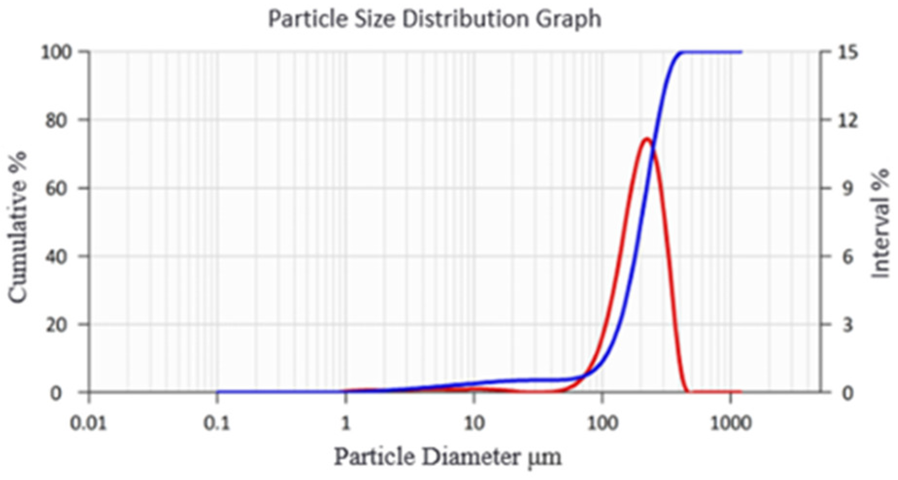
2.1. Materials

The materials used in this experiment included aggregate, cement, fly ash, desert sand, admixtures, and water.
(1) Coarse aggregate: The primary rock-fill aggregate consisted of waste concrete blocks with particle sizes ranging from 30 to 60 mm, sourced from discarded solid waste at the Heavy Equipment Laboratory of Xinjiang University. The shapes of these blocks are illustrated in Figure 1. Eighteen randomly selected blocks were tested using the point-load test, with the results summarized in Table 1. The average strength of the waste concrete was 50.05 MPa, consistent with the design principle of “strong aggregate–weak matrix.” Due to their rough, porous surfaces and irregular shapes, the waste concrete aggregates exhibited high water absorption, rapidly absorbing free water during mortar flow. This increased the flow resistance, adversely affecting mortar fluidity.
(2) Cement: Ordinary Portland cement (P.O42.5), conforming to the Chinese standard GB 175-2007 [25] (common Portland cement), was utilized. Chemical composition analysis was performed by the Aoshi Mineral Laboratory using X-ray fluorescence (XRF), with the primary chemical parameters shown in Table 2.
(3) Fly ash: Fly ash, a solid waste from coal-fired power plants, was tested at the Shandong Construction Engineering Quality Supervision and Testing Center and classified as Class F. Detailed parameters are listed in Table 3. Fly ash was incorporated to enhance the mortar fluidity, meeting the requirements of the rock-filled concrete process. In this technique, the mortar flows into the gaps of waste concrete aggregates solely through gravity, enabling automatic filling and leveling without vibration. Additionally, the pozzolanic activity of fly ash facilitates secondary reactions with cement hydration products, enhancing the long-term strength [26], durability, and overall performance of the filling material.
(4) Desert sand: Desert sand was collected from suburbs near Urumqi and analyzed by Dandong Better Instrument Co., Ltd., Dandong City, China. using a laser particle-size analyzer. The sand had a volumetric mean diameter of 201 μm and a numerical mean diameter of 1.5 μm. The particle size distribution is illustrated in Figure 2, where the blue curve represents the cumulative distribution and the red curve denotes the interval distribution.
(5) Chemical admixture: A standard polycarboxylate-based high-performance water reducer was used.
(6) Water: Ordinary tap water was employed.

2.2. Design Scheme

In this experiment, the influence of water-to-binder ratio and aggregate size of the waste concrete on the mechanical properties of the desert sand mortar cemented waste concrete filling material was investigated, while maintaining a constant content of desert sand. Aggregate sizes of the waste concrete were categorized into three groups: 30–40 mm, 40–50 mm, and 50–60 mm. These classifications were conducted using WipFrag 3.3 particle-size analysis software, as illustrated schematically in Figure 3.
Based on the designed proportions, eight groups of test specimens, each measuring 100 mm × 100 mm × 100 mm, were prepared, with three specimens per group, totaling 24 specimens. The amount of material per specimen is detailed in Table 4. The mass of coarse waste concrete aggregates in groups 4 to 8 was uniformly set at 1080 g per specimen. The total amount of waste concrete aggregate consumed in this experiment was 16.2 kg, equivalent to 1.08 tons per cubic meter.

2.3. Specimen Preparation

The preparation workflow appears in Figure 4 and included three steps.
(1)
Material batching: The cement, desert sand, fly ash, and water-reducing admixture were weighed according to the predetermined proportions, placed into a container, and thoroughly mixed to form a uniform dry mixture. Water was then added in three stages, mixing each time until a homogeneous paste was achieved.
(2)
Casting and curing: Waste concrete aggregates were manually and randomly placed into molds, simulating the natural, random filling pattern typical of backfilling open-pit mine voids, thus ensuring the realism and validity of the experiment. The prepared mortar was slowly poured into the mold from a fixed corner, allowing it to naturally infiltrate and fill gaps solely by gravity, without external vibration or compaction. Specimens were cured under standardized conditions at constant temperature and humidity (20 ± 2 °C, 95% RH) for 28 days. After curing, specimens were demolded, labeled, and organized neatly.
(3)
Speckle coating: One side of each specimen was sprayed with a speckle pattern, generating a random, high-contrast pattern suitable for tracking deformation and strain evolution before and after loading.

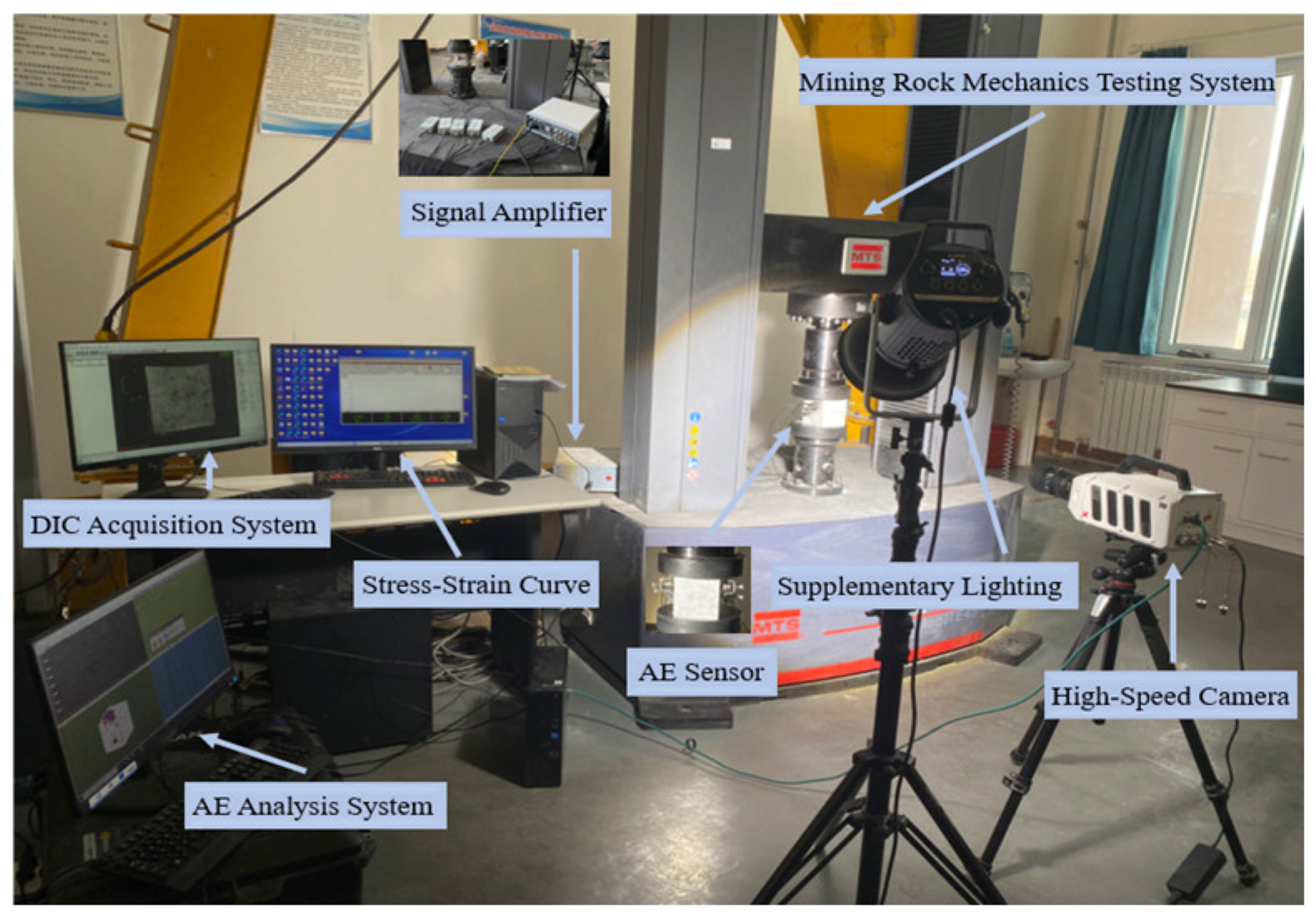
2.4. Testing Equipment

According to the standard GB/T50081-2019 [27], Standard Test Methods for Physical and Mechanical Properties of Concrete, a mining rock mechanics testing system was employed to conduct uniaxial compression tests. The displacement-controlled loading method was adopted, with a displacement rate of 0.5 mm/min. To capture the influence of aggregate particle size on crack initiation and propagation, digital image correlation (DIC) was used to record the full-field surface strain evolution of the specimens, while acoustic emission (AE) technology monitored the internal micro-fracturing signals. By analyzing localized strain patterns and AE frequency-domain energy distribution, the differences in damage accumulation and failure mechanisms among specimens with different aggregate sizes were quantitatively evaluated. The experimental setup is shown in Figure 5.
(1) Acoustic emission (AE): AE is a non-destructive testing technique used to monitor and analyze dynamic internal behaviors within materials or structures. In this experiment, five AE sensors were affixed to three surfaces of each specimen to capture transient elastic waves generated by internal microstructural changes [28]. Signals were preprocessed by amplifiers and filters and then transmitted to the analysis system for processing. Ring-down counts and three-dimensional localization were employed to reflect the crack propagation. Petroleum jelly was used as a coupling agent to close gaps between rough specimen surfaces and the AE sensors, ensuring the effective transmission of AE signals.
(2) Digital image correlation (DIC): DIC is a non-contact measurement technique based on image processing and pattern recognition. A high-speed camera with a resolution of 1280 × 1024 pixels was used, capturing images at a frequency of one frame per second. By analyzing the correlation of speckle images across different states, deformation information of the specimen surface was extracted and quantified with high precision. Advanced image processing algorithms were employed to measure and analyze the surface displacement and deformation [29].

3. Results and Discussion

3.1. Failure Patterns

Both the pure mortar subgroup specimens and aggregate-containing subgroup specimens underwent the following failure stages during loading.
Initially, neither type of specimen exhibited noticeable surface changes. At approximately 65% of peak strength, fine cracks appeared at the edges of the pure mortar subgroup specimens. For the aggregate-containing subgroup specimens, minor cracks emerged on both sides when the load reached around 80% of peak strength. As loading progressed, cracks in the pure mortar specimens rapidly propagated into penetrating cracks concentrated mainly along the edges. In comparison, the aggregate-containing specimens exhibited increasing numbers of combined diagonal and vertical cracks. Both specimen types showed small crushed fragments detaching from their edges during loading. Upon reaching the peak load, the penetrating cracks in the pure mortar specimens widened abruptly, leading to rapid structural failure along these weakened planes without an evident plastic deformation stage. In contrast, the aggregate-containing specimens developed multiple intersecting and irregularly distributed cracks, causing damage both at the aggregate–mortar interfaces and within the aggregates themselves. However, these specimens generally maintained structural integrity, demonstrating a residual load-bearing capacity even as the loading continued beyond the peak. Both specimen types eventually shed numerous stone fragments during failure, producing flake- and block-shaped debris. The typical final failure morphologies are presented in Figure 6.
The pure mortar specimens, lacking the dispersing and bridging effects of coarse aggregates, possessed a relatively homogeneous and compact internal structure, resulting in a characteristic brittle fracture under uniaxial compression. Due to their homogeneous nature, the stress distribution was relatively uniform, causing cracks to propagate along the weakest cross-sectional planes, resulting in penetrating cracks. These specimens rapidly fractured once reaching their ultimate compressive strength, without exhibiting a noticeable plastic deformation stage.
In contrast, the aggregate-containing specimens displayed a significantly irregular failure mode, primarily due to stiffness differences between the waste concrete aggregates and the mortar matrix. Introducing aggregates altered the internal stress-transfer mechanisms, creating complex stress concentration and shadow regions around aggregates and disrupting the otherwise uniform stress distribution. Consequently, cracks were forced to deflect or bifurcate upon encountering high-strength aggregates, causing tortuous crack propagation paths. Simultaneously, the aggregate–mortar interface, a structurally weak area, experienced debonding failure under composite stresses. This interfacial debonding interacted with the mortar cracks to form a network-like damage pattern. Compared with the gradual shear failure typical of conventional tailings-filled materials, these interfaces dispersed stress and absorbed energy, promoting crack bifurcation and energy dissipation. Elastic strain energy was thereby released through multiple pathways rather than concentrated along a single main crack. Thus, upon reaching peak compressive strength, the aggregate-containing specimens exhibited a plateau or gradually descending phase, demonstrating measurable plastic deformation capacity and residual load-bearing strength, contributing positively to the long-term stability of mining backfill structures.

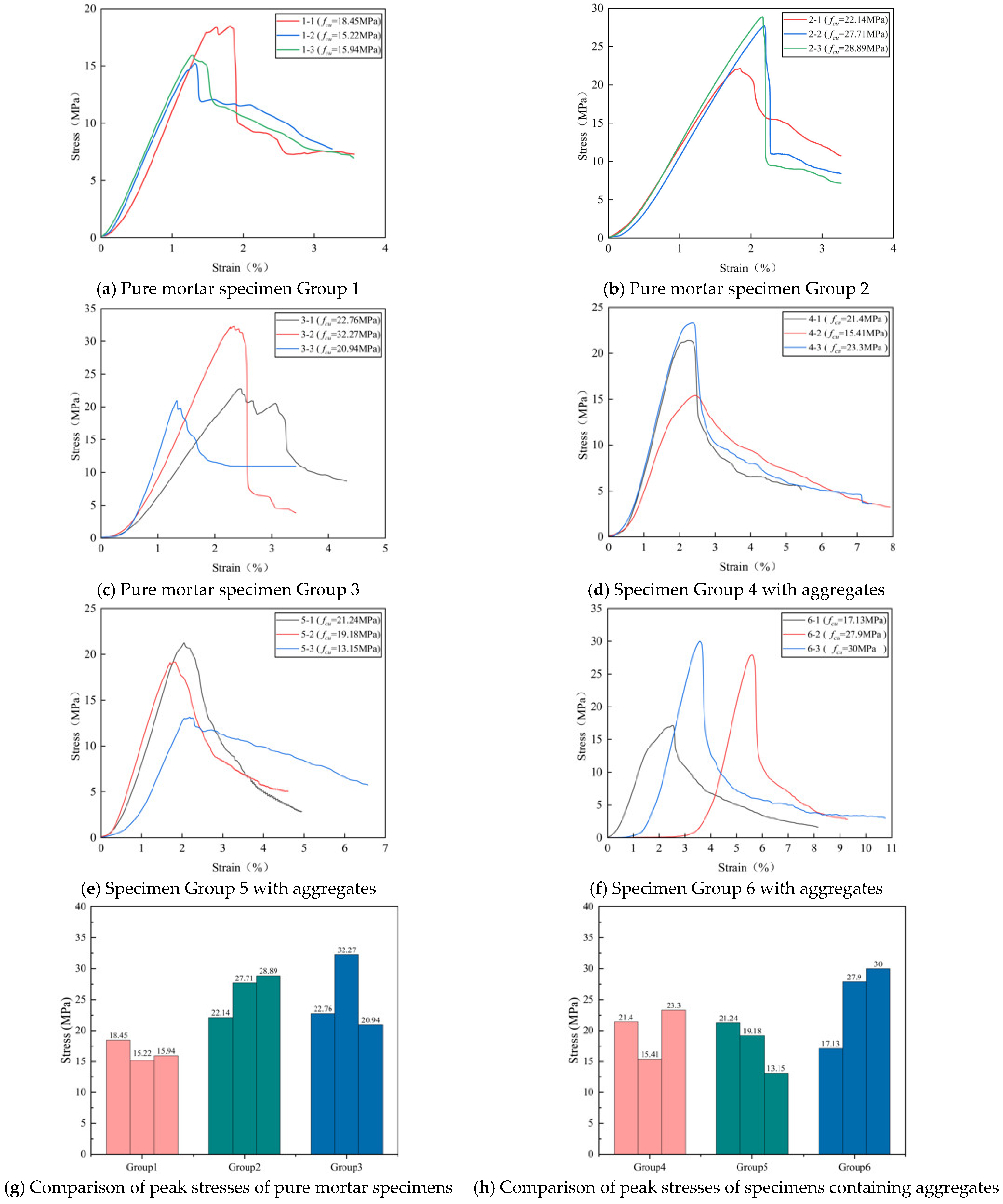
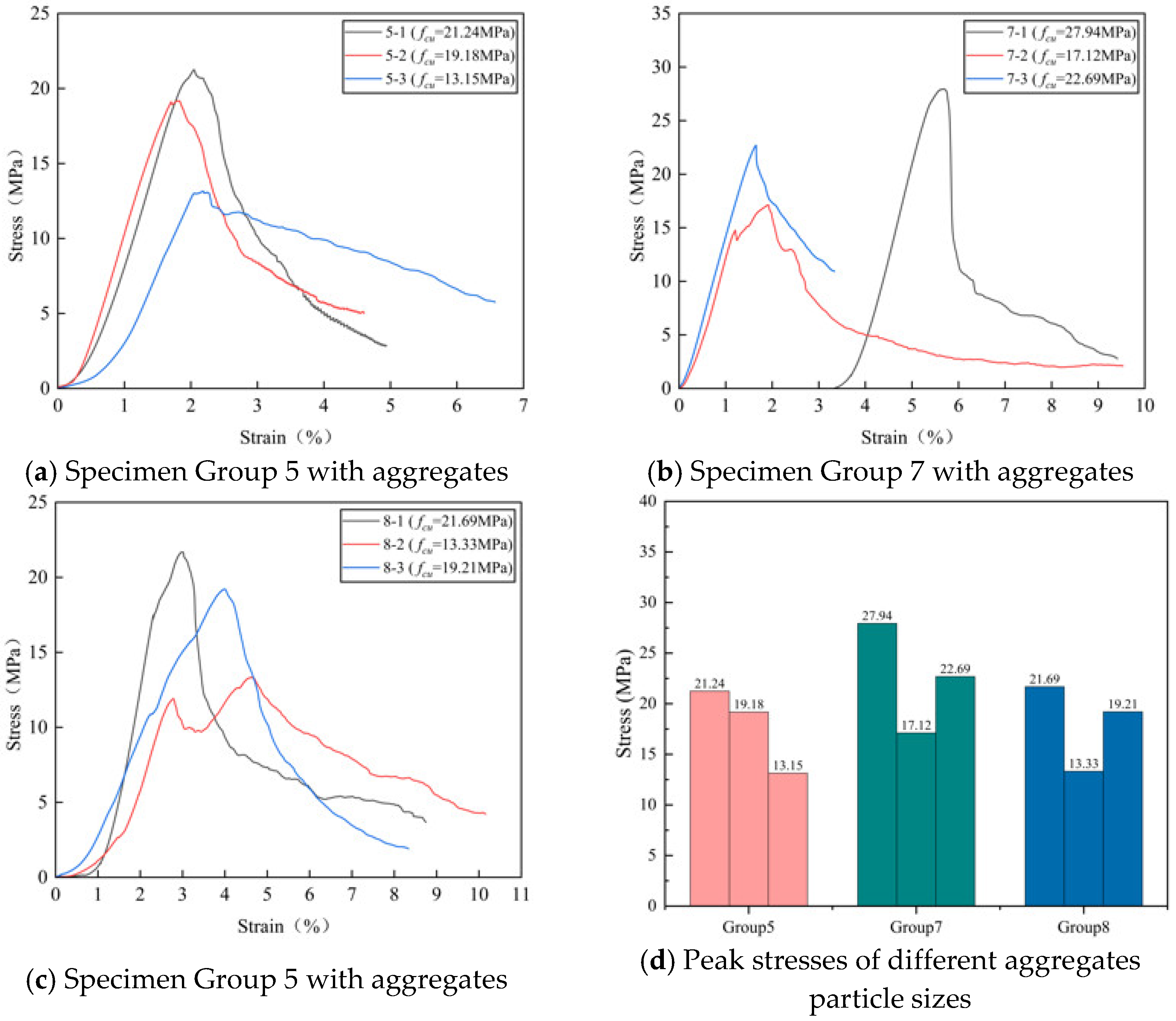
3.2. Stress–Strain Curve

Stress–strain curves derived from the uniaxial-compression tests revealed how both the water-to-binder ratio and the size of discarded-concrete aggregate affected the backfill behavior, as illustrated in Figure 7 and Figure 8.
(1) Different water-to-binder ratios: Figure 7 presents a comparison of peak strengths at varying water-to-binder ratios, involving a total of eighteen specimens divided into six groups: three pure mortar groups and three groups containing aggregates. Among the pure mortar groups, Group 1 exhibited a maximum stress of 18.45 MPa and an average strength of 16.54 MPa, while Group 2 demonstrated a significantly improved performance, with a maximum stress of 28.89 MPa and an average strength of 26.25 MPa. Group 3 reached a slightly higher maximum stress of 32.27 MPa but had a lower average strength (25.32 MPa) compared with Group 2. Thus, the mix ratio of Group 2 emerged as the optimal choice for pure mortar specimens, outperforming Group 1 by 58.7% and marginally surpassing Group 3 by approximately 4% in terms of average strength. Among the aggregate-containing groups, Group 4 attained a maximum stress of 23.3 MPa with an average of 20.04 MPa, whereas Group 5 yielded a maximum stress of 21.24 MPa and an average strength of 17.86 MPa. Group 6 significantly outperformed both, achieving a maximum stress of 30 MPa and an average strength of 25 MPa. Consequently, the water-to-binder ratio of Group 6 proved the most effective in enhancing the compressive strength among the aggregate-containing specimens. Overall, Groups 3 and 6 provided the most favorable water-to-binder ratios across all specimen types.
(2) Different aggregate particle sizes: In Figure 8, the effects of different aggregate particle sizes on peak strength were compared for Groups 5, 7, and 8. Group 5 (aggregate size of 30–40 mm) recorded a maximum stress of 21.24 MPa with an average strength of 17.86 MPa. Group 7, utilizing aggregates sized 40–50 mm, demonstrated a superior performance with a maximum stress of 27.94 MPa and an average strength of 22.58 MPa. Group 8, with aggregates of 50–60 mm, achieved a maximum stress of 21.69 MPa and an average strength of 18.08 MPa. The results indicated that aggregates sized between 40 and 50 mm significantly enhanced the mechanical performance, with the Group 7 specimens showing average strength improvements of 26.43% over Group 5 and 24.89% over Group 8.
Compared with traditional backfill materials, the newly developed mixtures demonstrated substantial performance advantages. The existing literature [30,31] reports typical 28-day strengths ranging from 2 to 10 MPa for cemented tailing backfills and 5 to 15 MPa for the cemented waste rock backfills, whereas the optimized mixtures in this study reached strengths of approximately 20–25 MPa, highlighting their superior suitability for mine backfilling applications.

4. Crack Development in Representative Specimens

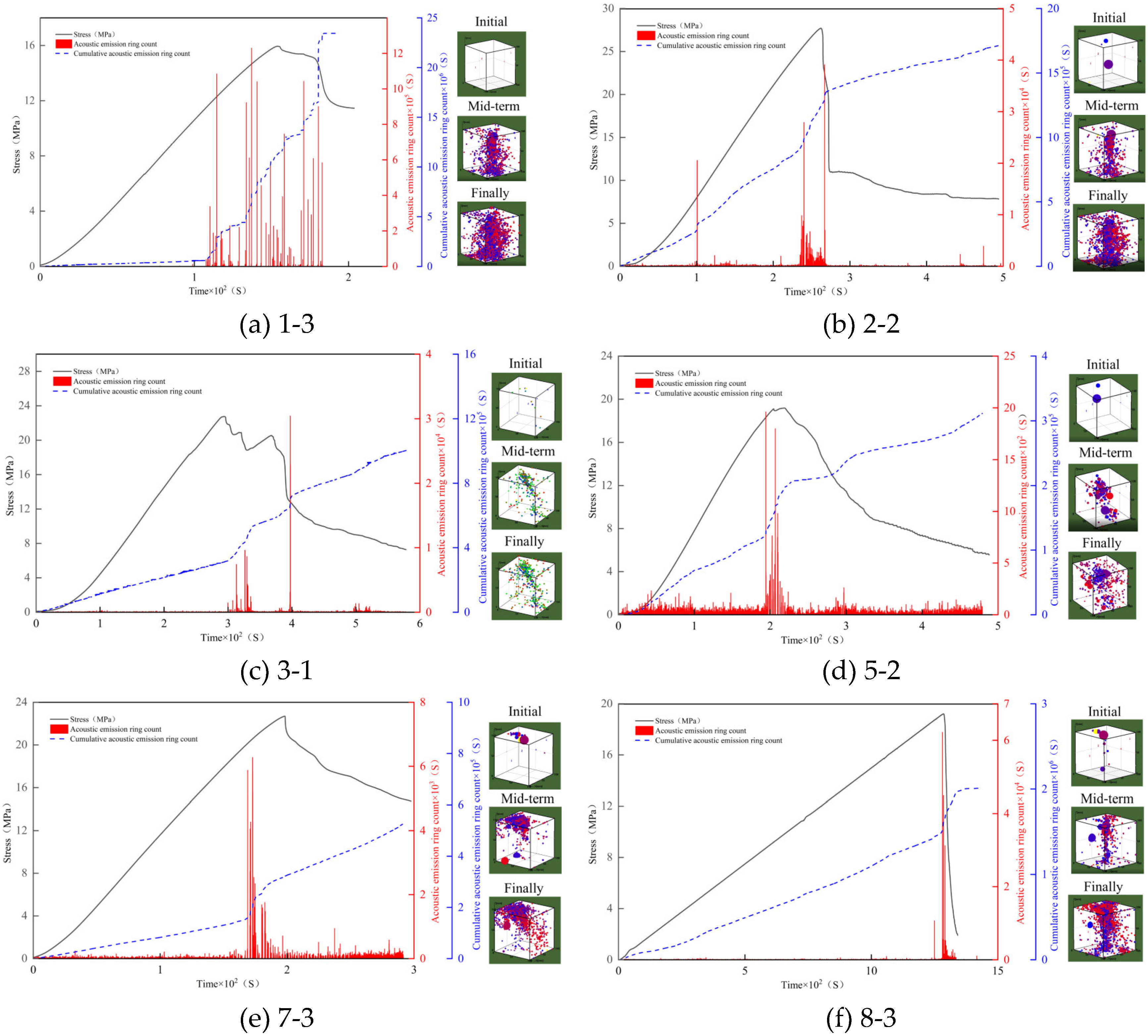
4.1. Stress–Strain Response and Acoustic Emission Activity

Acoustic emission (AE) signals originate from internal structural changes during compression, and therefore, the collected AE waveforms accurately reflect the internal crack development within the specimens. AE signals from loading tests were collected for six groups of specimens including pure mortar subgroups with different water-to-binder ratios and aggregate-containing subgroups with varying particle sizes. For each subgroup, the specimen with peak strength closest to the subgroup mean was selected as representative. The results are shown in Figure 9, with the damage process divided into three distinct stages.
The failure of the pure mortar subgroup specimens exhibited a clear three-stage progression. In the initial linear-elastic loading stage, the specimen experienced elastic deformation. A small number of air voids and micro-gaps created during specimen preparation were compacted under initial loading, resulting in sparse AE signals and a slow increase in cumulative ring-down counts. Strain-energy maps revealed uniform internal strain energy distributions without obvious stress concentrations, and 3D localization showed sparse, randomly distributed AE events. In the intermediate crack-development stage, the stress increased steadily, initiating micro-cracks in the specimen, which gradually connected and expanded. The AE signals intensified, causing the cumulative ring-down curve slope to rise sharply. Strain-energy maps began showing localized high-energy concentrations, primarily along specimen edges. Correspondingly, the 3D localization demonstrated AE sources progressively clustering toward potential failure surfaces, exhibiting clear spatial regularity. Finally, during the intense crack-propagation stage near peak loading, cracks widened significantly and rapidly expanded along planes of weakness. A dense burst of AE signals occurred, reflected by a steep ascent in the cumulative ring-down count curve. Strain-energy maps displayed characteristic continuous, high-energy bands, closely matching the final macroscopic crack patterns. 3D localization further confirmed rapid AE source convergence into linear failure zones, highlighting the intrinsic brittle fracture nature of pure mortar materials.
In contrast, the aggregate-containing subgroup specimens displayed markedly different three-stage failure mechanisms. In the initial linear-elastic loading stage, minor edge cracks appeared, accompanied by sparse AE signals, and the effect of the aggregate particle size was not yet evident. Strain-energy maps revealed localized disturbances around aggregates, but the energy remained broadly dispersed. AE events, as shown by 3D localization, were concentrated randomly near aggregate–mortar interfaces. In the intermediate crack-development stage, loading incrementally increased, promoting edge-crack propagation. Due to aggregate reinforcement, cracks developed irregularly, with vertical and inclined cracks forming simultaneously. As the AE signals intensified, the slope of the cumulative ring-down curve increased steadily. Strain-energy maps exhibited distinctly heterogeneous distributions, forming complex energy networks around aggregate boundaries. The AE source localization revealed spatially branched and multi-level distributions, highlighting the complex crack pathways around aggregates. In the final intense crack-propagation stage near peak load, cracks rapidly intersected and propagated, accompanied by dense AE signals. Specimens containing aggregates of 40–50 mm in particle size produced the highest AE signal intensities at peak load, reflecting the maximum fracture energy and corresponding to superior compressive strength, as shown by a significant rise in the cumulative ring-down count curve. Strain-energy maps indicated interconnected high-energy regions, forming intricate three-dimensional damage networks. The AE localization results revealed dense annular or spiral distributions around aggregates, confirming that the aggregates effectively dispersed and absorbed fracture energy by altering the crack propagation paths. This mechanism transformed the fracture behavior from a single brittle fracture mode to multi-scale progressive damage, enhancing the overall resilience and stability of the aggregate-containing backfill material.

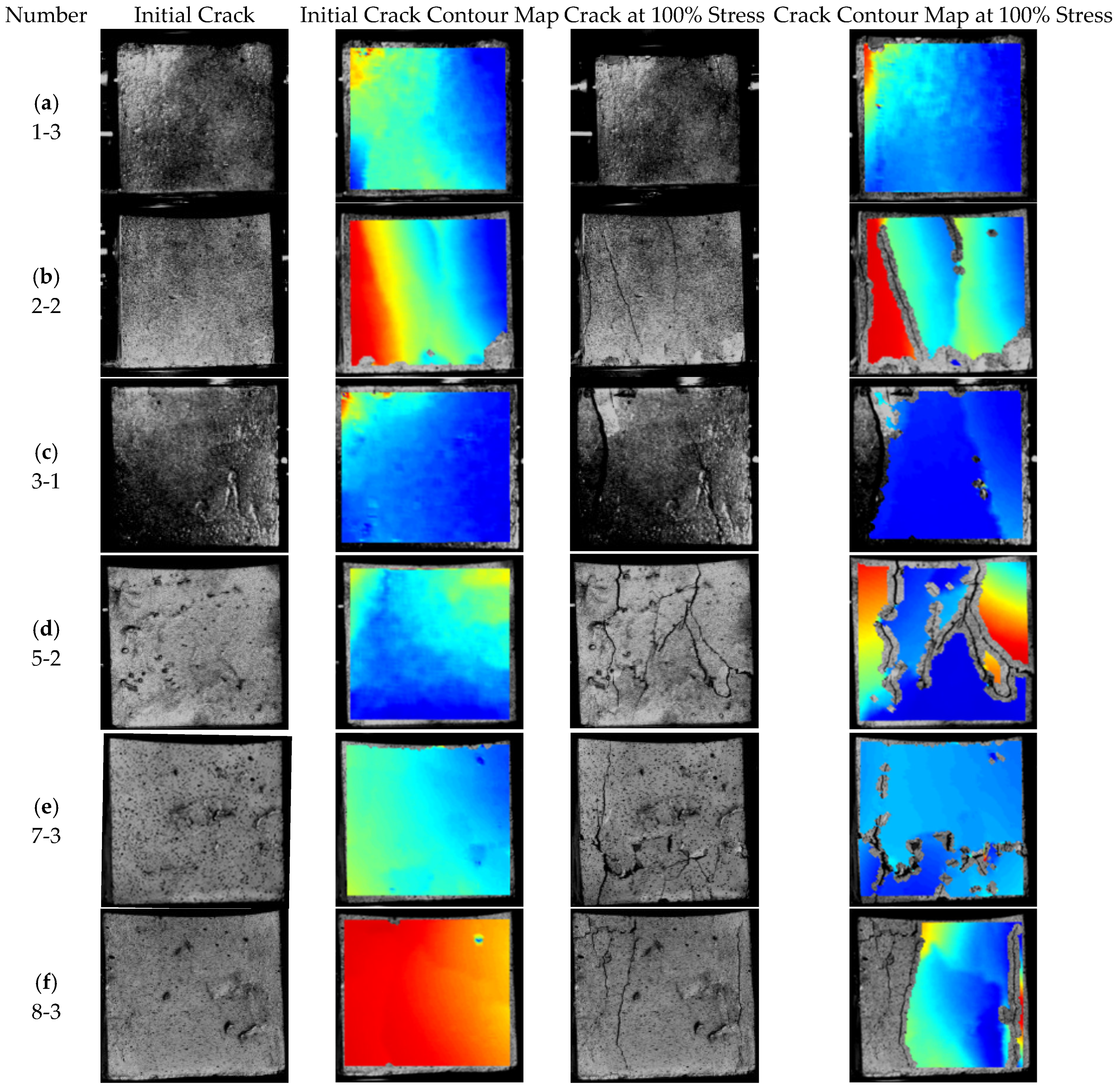
4.2. Crack Damage Evolution Captured by DIC

Speckle-image displacements recorded by digital image correlation (DIC) trace surface crack growth during compression. Six specimens were examined: three pure mortars with different water-to-binder ratios and three aggregate-containing mortars with different particle sizes. The specimen in each subgroup whose peak strength was closest to the group mean was selected for a detailed study. Figure 10 outlines how the initial cracks progressed to the fully loaded state, defined here as one hundred percent of peak stress.
In the pure mortar subgroups, very small strains were recorded at the start of loading, indicating that the accumulated energy was insufficient to drive crack growth. As the stress increased to about 65% of peak strength, microcracks appeared on the specimen surface, highlighting the localized stress–energy concentration. In the DIC energy maps, these zones are shown in red at the specimen edges, consistent with the failure analysis and displaying a predominantly vertical orientation. When the specimens reached peak strength, macroscopic, through-going cracks formed along these weak planes, matching the red high-energy bands on the maps.
The aggregate-containing group displayed a much more heterogeneous energy distribution. The presence of aggregate–mortar interfaces effectively dispersed stresses and absorbed energy, preventing the formation of clear, linear energy bands. In the early loading stage, initial cracks appeared on both sides of the specimens; on the energy maps, these regions appeared yellow, in agreement with the observed crack locations. At peak stress, macroscopic cracks in these specimens became intertwined and developed irregularly. Correspondingly, the energy maps showed a chaotic mix of red (highest energy), yellow (intermediate), and blue (lowest) regions, confirming that the aggregates obstructed straight crack propagation and forced the damage path to meander through the matrix.

5. Conclusions

This study combined uniaxial compression, digital image correlation (DIC), and acoustic emission (AE) monitoring to identify how the water-to-binder ratio and discarded concrete aggregate size influenced crack growth in cemented backfill. By linking failure modes, stress–strain behavior, AE activity, and full-field strain maps, five key findings emerged.
(1)
Under the action of uniaxial compression load, the pure mortar failed in a single, brittle split, while mixes with the discarded concrete aggregate developed curved and branching cracks that left some residual strength.
(2)
For the water-to-binder ratio, mixtures in Groups 3 and 6 (ratio = 0.30) outperformed the others with average strengths of roughly 25 MPa. A lower ratio reduced the porosity and strengthened the bond between the cementitious matrix and the aggregate.
(3)
Particles 40–50 mm in diameter offered the best mechanical performance (average strength ≈ 22.6 MPa). This size range formed a dense load-bearing skeleton, promoted crack deflection, and dissipated energy through interface friction.
(4)
The AE signals revealed three damage phases. Early loading produced low-energy hits tied to pore compaction. Mid-loading showed rising amplitude and frequency as microcracks propagated and interfaces deboned. Near peak load AE activity spiked, marking crack coalescence and final collapse.
(5)
DIC confirmed these trends. Pure mortar exhibited a single vertical strain band, whereas aggregate mixes displayed a complex network of strains that wrapped around particles and spread along interfaces, underscoring the aggregates’ role in redirecting cracks and absorbing energy.

Author Contributions

Conceptualization, H.C.; Methodology, H.C.; Funding acquisition, H.C.; Project administration, H.C.; Writing—review and editing, H.C.; Investigation, Z.Q., B.Y. and X.L.; Writing—original draft preparation, Z.Q.; Writing—review and editing, Z.Q.; Visualization, Z.Q., B.Y. and X.L. All authors have read and agreed to the published version of the manuscript.

Funding

This research was funded by the Key Research and Development Program of the Xinjiang Uygur Autonomous Region, China (2024B03014 and 2023B01010), Tianshan Talent Training Program (2023TSYCCX0095), The Basic Research Funding for Universities of Xinjiang Uygur Autonomous Region (XJEDU2022P013), and the Natural Science Foundation of Xinjiang Uygur Autonomous Region (2022D01C411).

Data Availability Statement

All data generated or analyzed during this study are included in this published article. For additional information or to request the raw data, please contact the corresponding author: Zhiyuan Qi, by Email: qzyqizhiyuan@163.com.

Acknowledgments

We would like to express our sincere gratitude to Xinjiang University for providing the platform support, and also extend our heartfelt thanks to the classmates and teachers who assisted during the paper editing process.

Conflicts of Interest

The authors declare that they have no known competing financial interests or personal relationships that could have appeared to influence the work reported in this paper.

References

  1. Ye, L.Q.; Xu, X.C.; Gu, X.W.; Wang, Q. Ecological Cost of Open-Pit Coal Mine in Semi-arid Ecologically Fragile Area of Xinjiang. J. Northeast. Univ. (Nat. Sci. Ed.) 2023, 44, 1318–1327. [Google Scholar]
  2. Liu, G. Analysis of geological disaster types and control measures in coal mine goaf areas. West. Min. Eng. 2024, 36, 3–6. [Google Scholar]
  3. Wang, S.; Yue, Z.; Kang, Y.; Luo, L. Research on the application status and material properties of aeolian sand backfill mining. J. Min. Sci. 2024, 9, 217–232. [Google Scholar]
  4. Mohapatro, R.N.; Swain, R.; Routray, S.; Shadangi, K.P.; Mohanta, S.; Sarangi, P.K.; Gollakota, A.R. Recovery of filler material from mining waste: Techno-economic and kinetic study. Process Saf. Environ. Prot. 2024, 185, 918–929. [Google Scholar] [CrossRef]
  5. da Silva, A.; Miguel, G.D.; Daronco, J.V.L.; Coelho, P.O.D.P.; Festugato, L. Influence of curing under stress on the geomechanical response of cemented iron ore mining tailings subjected to distinct effective stress paths. Int. J. Geomech. 2024, 24, 04024159. [Google Scholar] [CrossRef]
  6. Zhu, T.; Chen, Z.; Cao, J.; Nian, G.; Zhang, L.; Hao, J.; Zhou, Z. Investigation of the fracture behavior of cemented waste rock-tailing backfill by digital image correlation technique and discrete element modeling. Constr. Build. Mater. 2024, 428, 136367. [Google Scholar] [CrossRef]
  7. Du, J.; Pan, S.; Liu, C.; Wei, Y.; Lu, Y.; Pan, H.; Qi, K.; Zhao, M.; Liu, H.; Yao, H.; et al. Key grouting technology and engineering demonstration for green mines. J. Min. Sci. 2023, 8, 293–307. [Google Scholar]
  8. Qiang, H. Green governance of domestic mining industry from the perspective of the Chinese path to modernization: Risks, bottlenecks and paths. Chem. Ind. Miner. Process. 2023, 52, 69–76. [Google Scholar]
  9. Yao, N.; Liu, Y.; Wang, Q.; Oppong, F.; Huang, T.; Zhou, Z.; Du, P. Experimental study on delamination and strength characteristics of cemented waste rock backfill. Constr. Build. Mater. 2023, 365, 130058. [Google Scholar] [CrossRef]
  10. Li, J.; Li, A.; Hao, J.; Xu, J.; Zhang, L. Experimental study on the ratio between ti-bearing blast furnace slag-iron-based full tailing sand and cement in cementitious filling. J. Min. Sci. 2023, 8, 838–846. [Google Scholar]
  11. Liu, F. Surrounding Rock Control Technology of Large Section Chambers in Deep Goaf of Coal Mines. Shanxi Coal 2024, 44, 18–23. [Google Scholar]
  12. Tang, Y.; Zhang, L.; Lu, H. Study on proportion optimization of coal-based solid wastes filling materials. J. Min. Sci. Technol. 2019, 4, 327–336. [Google Scholar]
  13. Yu, W.; Sun, M.; Du, J.; Chen, G.; Wang, C. Research progress on the approach for ecological restoration of mines, emission reduction, and carbon sink growth under the goal of carbon peak and carbon neutrality. Min. Saf. Environ. Prot. 2025, 52, 38–46. [Google Scholar]
  14. Du, K.; Xie, J.; Xi, W.; Wang, L.; Zhou, J. Construction practices of green mines in China. Sustainability 2024, 16, 461. [Google Scholar] [CrossRef]
  15. Wang, X.; Wang, Z.; Xu, H.; Zhang, S.; Zhang, F. Rheological Properties and Consolidation Mechanism of Cement-Fly Ash Cemented Gangue Backfill Material. Nonferrous Met. Eng. 2024, 14, 134–143. [Google Scholar] [CrossRef]
  16. Jia, X.; Feng, G. Influence of Fine Aggregate from Waste Concrete on the Performance of Backfill Paste. Min. Res. Dev. 2015, 35, 37–40. [Google Scholar]
  17. Ding, X.; Du, H.; Wu, E.; Yi, P.; Li, Y.; Luo, Y.; Liu, W. Investigating the Hydration, Mechanical Properties, and Pozzolanic Activity of Cement Paste Containing Co-Combustion Fly Ash. Buildings 2024, 14, 130. [Google Scholar] [CrossRef]
  18. Hong, Z.J.; Li, Z.H.; Du, F.; Xu, L.; Zhu, C. Experimental investigation of the mechanical properties and large-volume laboratory test of a novel filling material in mining engineering. Geomech. Geophys. Geo-Energy Geo-Resour. 2023, 9, 46. [Google Scholar] [CrossRef]
  19. Zhang, M.; Liu, H.; Sun, S.; Chen, X.; Doh, S.I. Dynamic mechanical behaviors of desert sand concrete (DSC) after different temperatures. Appl. Sci. 2019, 9, 4151. [Google Scholar] [CrossRef]
  20. Wang, H.; Wang, Q.; Gao, T.; Wang, J.; Sun, C.; Ji, Z.; Meng, J.; Ta, B. Analysis of strength failure in gangue-based cementitious backfill body from a microscopic perspective. PLoS ONE 2024, 19, e0300102. [Google Scholar] [CrossRef]
  21. Wang, J.; Li, H.; Qiu, Z. Study on mechanical properties of recycled large aggregate-self-compacting mortar rock-filled concrete. J. Archit. Sci. Eng. 2023, 40, 21–27. [Google Scholar]
  22. Wang, H.; Ma, J.; Zhou, H.; He, S.; Jin, F. Uniaxial compressive mechanical properties of rockfill concrete. J. Tsinghua Univ. (Sci. Technol.) 2022, 62, 339–346. [Google Scholar]
  23. Ruslan, H.N.; Muthusamy, K.; Yahaya, F.M.; Fauzi, M.A.; Ismail, M.A.; Ali, Z. Review on performance of self-compacting concrete containing solid waste and bibliometric properties: A review. J. Build. Eng. 2024, 86, 108752. [Google Scholar] [CrossRef]
  24. Alterary, S.S.; Marei, N.H. Fly ash properties, characterization, and applications: A review. J. King Saud Univ. Sci. 2021, 33, 101536. [Google Scholar] [CrossRef]
  25. GB 175-2007; Common Portland Cement. Standards Press of China: Beijing, China, 2007.
  26. Wang, X.; Liu, S.; Liu, X.; Shan, T.; Zhou, X.; Xie, H.; Wang, J. Mode I fracture propagation and post-peak behavior of sandstone: Insight from AE and DIC observation. Eng. Fract. Mech. 2024, 302, 110093. [Google Scholar] [CrossRef]
  27. GB/T 50081-2019; Standard for Test Methods of Physical and Mechanical Properties of Concrete. Standards Press of China: Beijing, China, 2019.
  28. Hou, C.; Wang, C.; Dias, D. Damage Constitutive Model for Freeze-Thawed Rock: Considering Damage Threshold and Residual Strength. Geotech. Geol. Eng. 2025, 43, 1–13. [Google Scholar] [CrossRef]
  29. Cui, Y.; Pu, Y.; Chen, Z.; Mengli, D.; Chen, J. Experimental study on the mechanical properties and crack evolution patterns of sandstone with prefabricated double fractures in the sub-instability stage. J. Min. Sci. Technol. 2025, 10, 194–202. [Google Scholar]
  30. Siddique, S.; Jang, J.G. Assessment of molybdenum mine tailings as filler in cement mortar. J. Build. Eng. 2020, 31, 101322. [Google Scholar] [CrossRef]
  31. Chen, G.; Yao, N.; Ye, Y.; Fu, F.; Hu, N.; Zhang, Z. Study on mechanical properties and damage characteristics of cemented waste rock-tailing backfill. Environ. Sci. Pollut. Res. 2023, 30, 102181–102197. [Google Scholar] [CrossRef]
Figure 1. Discarded concrete blocks.
Buildings 15 02060 g001
Figure 2. Particle-size distribution of the desert sand.
Buildings 15 02060 g002
Figure 3. Size classification of the discarded concrete aggregates.
Buildings 15 02060 g003
Figure 4. Specimen preparation process.
Buildings 15 02060 g004
Figure 5. Test system setup.
Buildings 15 02060 g005
Figure 6. Typical failure modes for the pure mortar and aggregate specimens.
Buildings 15 02060 g006
Figure 7. Stress–strain relationship of specimens with different water–binder ratios.
Buildings 15 02060 g007
Figure 8. Stress–strain relationship of different aggregate particle sizes.
Buildings 15 02060 g008
Figure 9. Evolution of stress and acoustic emission ring-down counts for representative specimens.
Buildings 15 02060 g009
Figure 10. Evolution of surface cracks in the test specimens.
Buildings 15 02060 g010
Table 1. Compressive strength of the discarded concrete coarse aggregate.
Number123456789
Rc/MPa44.7939.4550.1748.0743.1947.653.5259.7747.11
Number101112131415161718
Rc/MPa45.1156.2750.563.4543.5650.642.6159.1356.07
Table 2. Chemical composition of the cement.
Detection LimitAl2O3WLaLiSiO2CaO
Measured Value%μg/gμg/gμg/g%%
Detection limit0.011010100.010.01
Measured value5.2810202024.7056.6
Table 3. Properties of the fly ash.
ItemFineness (%)Water-Demand
Ratio
Loss on
Ignition (%)
Moisture (%)SO3 (%)Free CaO (%)Alkali
Content (%)
Test results (%)8.0802.00.11.50.20.1
Table 4. Mix proportions per specimen.
NumberWaterFly AshCementDesert SandAggregate SizeSuperplasticizerAggregate Percentage
(ml)(g)(g)(g)(mm)(g)(%)
Pure mortar
subgroup
121052.5472.5720010
221060540720010
321070630720010
Aggregate-
containing
subgroup
421052.5472.572030~40142.6
52106054072030~40141.4
62107063072030~40139.9
72106054072040~50141.4
82106054072050~60141.4
Disclaimer/Publisher’s Note: The statements, opinions and data contained in all publications are solely those of the individual author(s) and contributor(s) and not of MDPI and/or the editor(s). MDPI and/or the editor(s) disclaim responsibility for any injury to people or property resulting from any ideas, methods, instructions or products referred to in the content.

