1. Introduction
With the advancement of urbanization and the continuous increase in building density, deep foundation pit engineering has become a mainstream practice in modern urban construction to enhance land space utilization. Consequently, the proximity between newly excavated foundation pits and existing structures has significantly decreased [
1]. Certain structures, such as underground pipelines, tunnels, and historical buildings, are highly sensitive to ground deformation induced by foundation pit excavation [
2,
3,
4,
5,
6,
7]. Therefore, the effective control of excavation-induced deformation is of critical importance.
Over the past few decades, ordinary steel struts have been widely adopted in foundation pit strut systems owing to their straightforward installation and effectiveness in prestress deformation control [
8,
9,
10]. However, studies reveal that temperature fluctuations and stress relaxation frequently lead to prestress loss in these struts, with losses reaching 49–67% in practical foundation pit applications [
11,
12]. Consequently, a servo-controlled steel strut system capable of axial force and length adjustment has been innovatively developed. The servo steel strut system adopts a dual-jack configuration (with one jack installed at each end of every strut), establishing real-time communication between the jacks and the control pump station via data cables. This system integrates the dual functions of axial force monitoring and hydraulic adjustment, enabling operators to manually regulate the axial force or length based on monitoring data, thereby effectively controlling the deformation development of the diaphragm wall. In recent years, such servo strut systems have been increasingly utilized to control excavation-induced deformations, demonstrating satisfactory control effectiveness in several projects [
13,
14,
15,
16].
However, in certain foundation pit projects employing servo steel struts, the deformation control results have proven unsatisfactory, largely attributable to the lack of proper design methodologies for these systems. In response to this challenge, scholars have systematically investigated the deformation control mechanisms of servo strut systems through theoretical analyses, model tests, and numerical simulations. In terms of theoretical analyses, Li et al. [
17], based on the beam–spring model, proposed a simplified calculation method for diagram wall displacement induced by excavation under the action of servo axial forces. Huang et al. [
18] derived the control algorithm for the force and deformation of the supporting structure with servo steel struts, concluding that using a “concentrated force + spring element” mixed boundary condition could simulate the effect of servo steel struts on the retaining structure, and they established a horizontal displacement balance equation for the retaining wall, considering servo axial forces. In terms of model tests, Jin et al. [
19] explored the impact of axial force adjustment on wall displacement and found that the horizontal influence range of loading by servo struts is 3 times the horizontal strut distance. Chen et al. [
14] proposed a novel deep excavation strut system capable of adjusting strut length through axial force variation and conducted a series of model tests to investigate the effects of internal strut length on the mechanical and deformation characteristics of excavations. Di et al. [
20] revealed that both the axial force and elongation length of servo struts significantly influence retaining wall displacement, with length variation demonstrating more pronounced effects on soil pressure distribution and wall displacement than force adjustment. In terms of numerical simulations, Li et al. [
16] carried out numerical simulations to verify the effectiveness of the servo strut system in controlling wall displacement and ground surface settlement. Sun et al. [
21] studied and discussed the control effect of axial force servo systems in retaining structures on lateral deformation under different settings for a two-layer and three-layer underground station excavation in a soft soil area, concluding that with the same number of servo systems, the control effect on the lateral deformation of the retaining structure was more significant closer to the bottom of the excavation.
In summary, while existing studies have investigated the influence of servo struts on lateral soil pressure and wall displacement, the combined effects of simultaneously activated multi-level struts with different configurations remain unexplored. This knowledge gap significantly impedes the optimization of servo loading strategies. This study conducts model tests to investigate, firstly, the mechanical behavior and deformation characteristics of foundation pits during excavation stages, and secondly, the effects of different servo strut configurations on both the strut structure and surrounding soil. This comprehensive analysis encompasses diaphragm wall displacement, bending moment, lateral soil pressure, ground surface settlement, and surrounding soil pressure, with the findings providing practical recommendations for engineering applications.
2. Deep Foundation Pit Model Test
2.1. Design of the Test Setup and Material Parameters
Figure 1 shows the model test apparatus. The dimensions of the test model were as follows: length × width × height = 2500 mm × 2000 mm × 1500 mm. To maintain geometric similarity and considering the effects of boundary and size [
15], a 1:25 scale was adopted. Given the focus on static behavior, stress and dynamic similarity laws were not strictly enforced. The model aimed to observe relative deformation responses under different servo conditions rather than precise stress fields. The boundary influence was controlled by ensuring that the model boundary was sufficiently distant from the active deformation zone.
Due to the symmetry of the excavation, a partially open excavation model was adopted. The dimensions of the simulated foundation pit were as follows: length × width × depth = 2000 mm × 480 mm × 680 mm. The strut system consisted of a combination of diaphragm walls and internal struts. The diaphragm wall was designed based on the equivalent bending stiffness principle [
16], with the following dimensions: length × height × thickness = 2000 mm × 1200 mm × 5 mm, using aluminum alloy plates. In sandy soils, when the embedment ratio exceeds 0.46 [
22], the base of the diaphragm wall can be idealized as a fixed constraint. An extended proof-sand membrane was installed between the diaphragm wall and model sidewall, which not only effectively prevented backfill sand from flowing into the foundation pit during excavation, but also significantly reduced frictional interaction between the wall and sidewall.
The internal struts were designed according to the equivalent compressive stiffness principle [
23], consisting of telescopic hollow aluminum rods with an outer diameter of 10 mm and an inner diameter of 7 mm. The struts were arranged horizontally in six rows, with a spacing of 320 mm, and vertically in four rows, with a spacing of 170 mm. The minimum resolution of the telescopic device was 0.104 mm. The soil was simulated using homogeneous dry sand, with the material parameters provided in
Table 1.
2.2. Point Layout of the Experiment
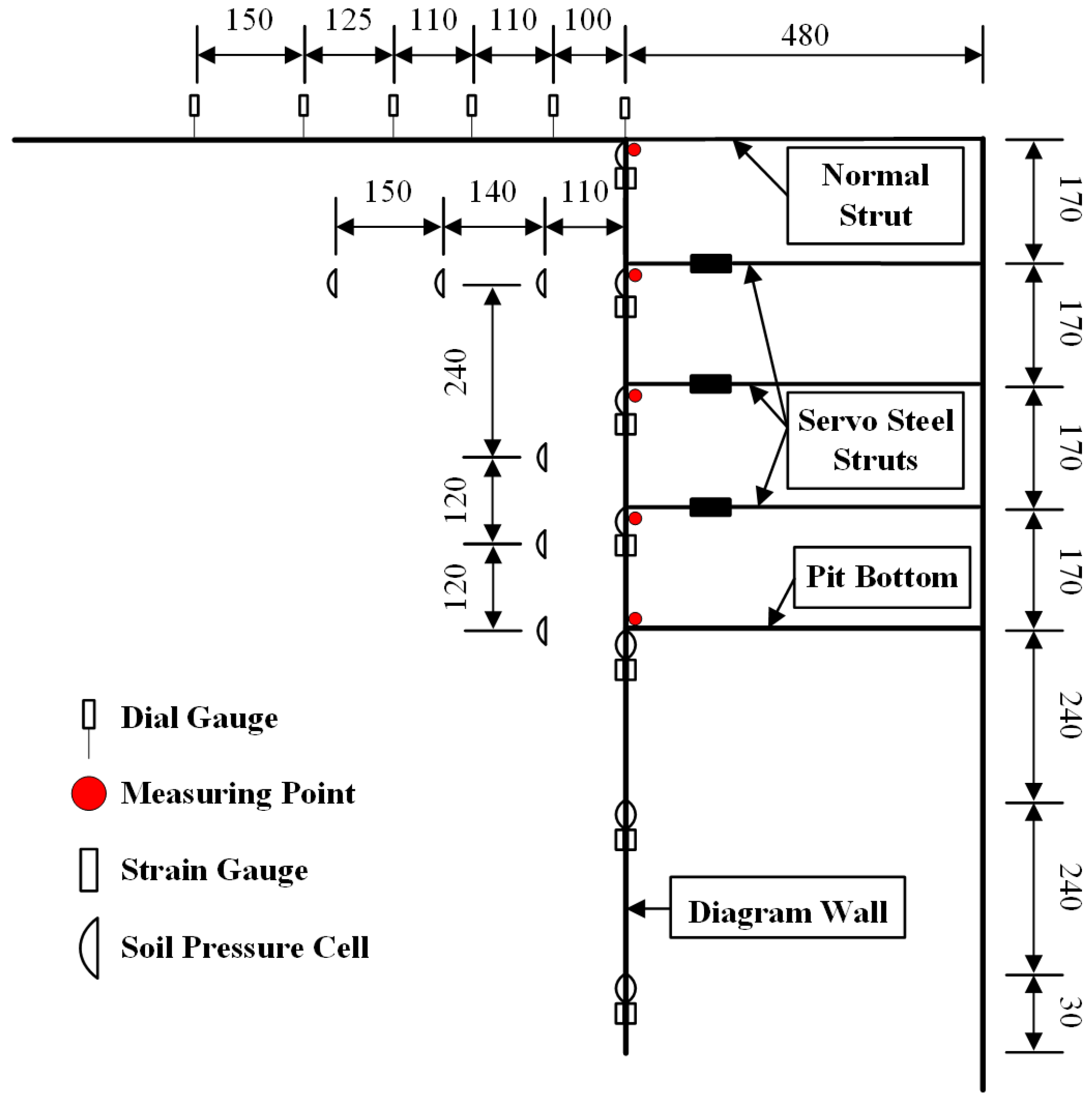
Figure 2 is the layout of the test points.
Table 2 is the test monitoring scheme. The monitoring section is selected at the central position of the foundation pit. In this model test, 5 displacement points along the depth direction of the diaphragm wall are monitored using a combination of laser displacement sensors and supporting components.
The testing method is as follows: During the filling stage, the base of the laser displacement sensor is placed against the side wall of the model, and the other end of the laser displacement sensor directs the laser onto the measurement point on the diaphragm wall, thus measuring the initial position value
ai. After the simulated foundation pit excavation is completed, the same method is used to measure the position value
bi of the diaphragm wall. The horizontal displacement at the end of excavation is calculated as
bi −
ai. After servo loading, the position value
ci of the diaphragm wall is measured again. The horizontal displacement change under the servo loading is
ci −
bi. A micrometer is arranged at the top of the diaphragm wall to monitor vertical displacement. Seven strain gauges are installed along the depth direction of the diaphragm wall, and the bending moment is calculated using strain data and the bending moment formula. A total of 16 miniature soil pressure cells are installed within the surrounding soil to monitor the soil pressure. Six digital micrometers are placed on the surface around the pit to monitor the surface settlement. The range and accuracy of the measuring instruments are shown in
Table 2 and the specific point layout is shown in
Figure 2.
2.3. Experimental Procedure and Working Conditions
The model test procedure is as follows: (1) Preparation and Soil Filling Phase: Strain gauges and soil pressure cells are installed at pre-determined points on the diaphragm wall. Sand is filled in layers of 10 cm each, and compacted with a heavy hammer to control the relative density of the soil at 0.75 (dense). When the filling reaches 310 mm from the bottom of the excavation, the diaphragm wall is placed. The gap between the diaphragm wall and the model is sealed with a sand-proof membrane, leaving some space for thermal expansion. Sand filling continues, and soil pressure cells are placed according to the location of the surrounding pressure points. After filling the sand, the corresponding digital micrometers are set up for displacement points.
(2) Excavation Phase: Before excavation, the data acquisition system is checked to ensure proper operation, and data is reset to zero. After each layer of soil is excavated, it is left for 3 h to ensure stable data collection. The specific excavation process is as follows: The top layer of sand (3 cm) is excavated, and the first strut is installed. The first layer of soil is excavated to −17 cm, and the second strut is installed. The second layer of soil is excavated to −34 cm, and the third strut is installed. The third layer of soil is excavated to −51 cm, and the fourth strut is installed. The fourth layer of soil is excavated to −68 cm.
(3) Servo Strut Adjustment Phase: After the excavation is complete and the system has rested for 24 h to allow for the stabilization of the soil, the servo loading system is simulated by extending steel struts. The extension distance for each steel strut is determined by the horizontal displacement of the diaphragm wall measured using a laser displacement sensor after the excavation.
The tests are shown in
Table 3. A total of eight independent experiments are designed, with each test consisting of both the excavation phase and the servo loading phase.
3. Model Test Results Analysis
The following mainly analyzes the monitoring data under different tests in the model test (without scaling according to the reduction ratio). The analysis includes aspects such as diaphragm wall displacement, bending moment, lateral soil pressure, as well as surface settlement and surrounding soil pressure, covering both the excavation and servo loading stages.
3.1. Horizontal Displacement of the Diaphragm Wall
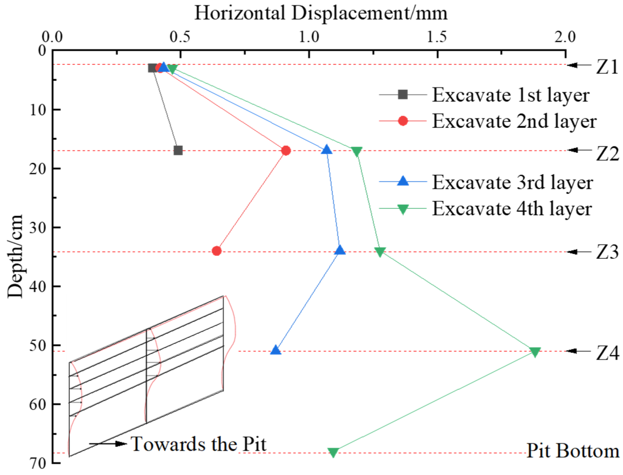
Figure 3 shows the horizontal displacement variation in the diaphragm wall during the excavation stage of the foundation pit, as measured by a laser displacement sensor. In the figure, Z1–Z4 represent the first to fourth layers of the internal struts. It is defined that a positive displacement indicates movement toward the pit, while a negative displacement indicates movement away from the pit. As shown in the figure, after the excavation of the first layer of soil, the maximum displacement of the diaphragm wall is 0.49 mm; after the second layer of soil excavation, it is 0.91 mm; after the third layer of soil excavation, it is 1.12 mm; and after the fourth layer of soil excavation, the diaphragm wall reaches its maximum displacement of 1.88 mm (approximately 0.276%
H, where
H is the excavation depth of the foundation pit), which occurs at a depth of 51 cm (approximately 0.75
H). As the foundation pit unloading progresses, the maximum displacement of the diaphragm wall gradually increases, and the location of maximum displacement also moves downward. After the excavation is completed, the overall deformation of the diaphragm wall presents an “expanding belly” shape.
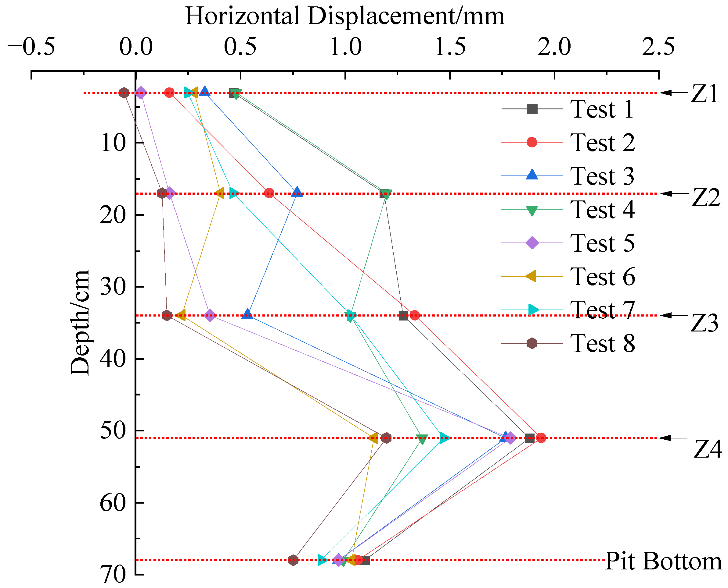
Figure 4 shows the horizontal displacement variation in the diaphragm wall under different combinations of servo steel struts, and
Table 4 provides the control quantity and control effect of the maximum displacement of the diaphragm wall under different combinations of servo steel struts. From the figure and table, the following can be concluded: (1) When the servo steel struts extend, the horizontal displacement of the diaphragm wall near the struts decreases. The impact of strut extension on the deformation of the diaphragm wall varies at different depths. When the upper strut (Z2) extends, the horizontal displacement at the top of the wall is effectively controlled, but the displacement at the bottom of the wall increases. When the lower struts (Z3, Z4) extend, the effect on the top of the wall is minor, but the horizontal displacements at other positions are reduced. Considering that the maximum horizontal displacement of the diaphragm wall usually occurs near the excavation face in actual engineering, the struts extended at deeper positions are more beneficial for controlling the deformation of the diaphragm wall. (2) Furthermore, the data from
Table 4 shows that the control effect of using the servo system in the third and fourth layers is better than in the second, third, and fourth layers, and the control effect of the servo system in the fourth layer is better than in the second and third layers. This indicates that when the servo steel strut is improperly placed, the control effect on diaphragm wall displacement is not proportional to the number of layers. In engineering projects, considering both economy and rationality, servo steel struts should be placed at the bottom of the excavation, and the more layers of struts, the better the control effect on diaphragm wall displacement.
It is noted that the horizontal displacement measurements, while in the sub-millimeter range, were well above the resolution threshold of the sensors (0.03 mm), and measurement uncertainty was within ± 0.03 mm during calibration. Therefore, the relative comparisons between different loading conditions remain valid. However, confidence intervals and standard deviations were not included due to single-run constraints and will be a focus in future studies.
3.2. Vertical Displacement of the Diaphragm Wall
Figure 5 shows the vertical displacement variation in the diaphragm wall with the excavation of the pit. As illustrated, the excavation leads to the unloading of the soil, causing stress release in the soil within the pit. This results in an uplift at the pit bottom, which also drives the diaphragm wall to move upward. At the same time, the excavation process is accompanied by the installation of internal struts, which exert a back-push effect on the diaphragm wall, further intensifying the uplift. The maximum uplift of the diaphragm wall is 0.073 mm. This observed behavior is consistent with previous studies [
24,
25].
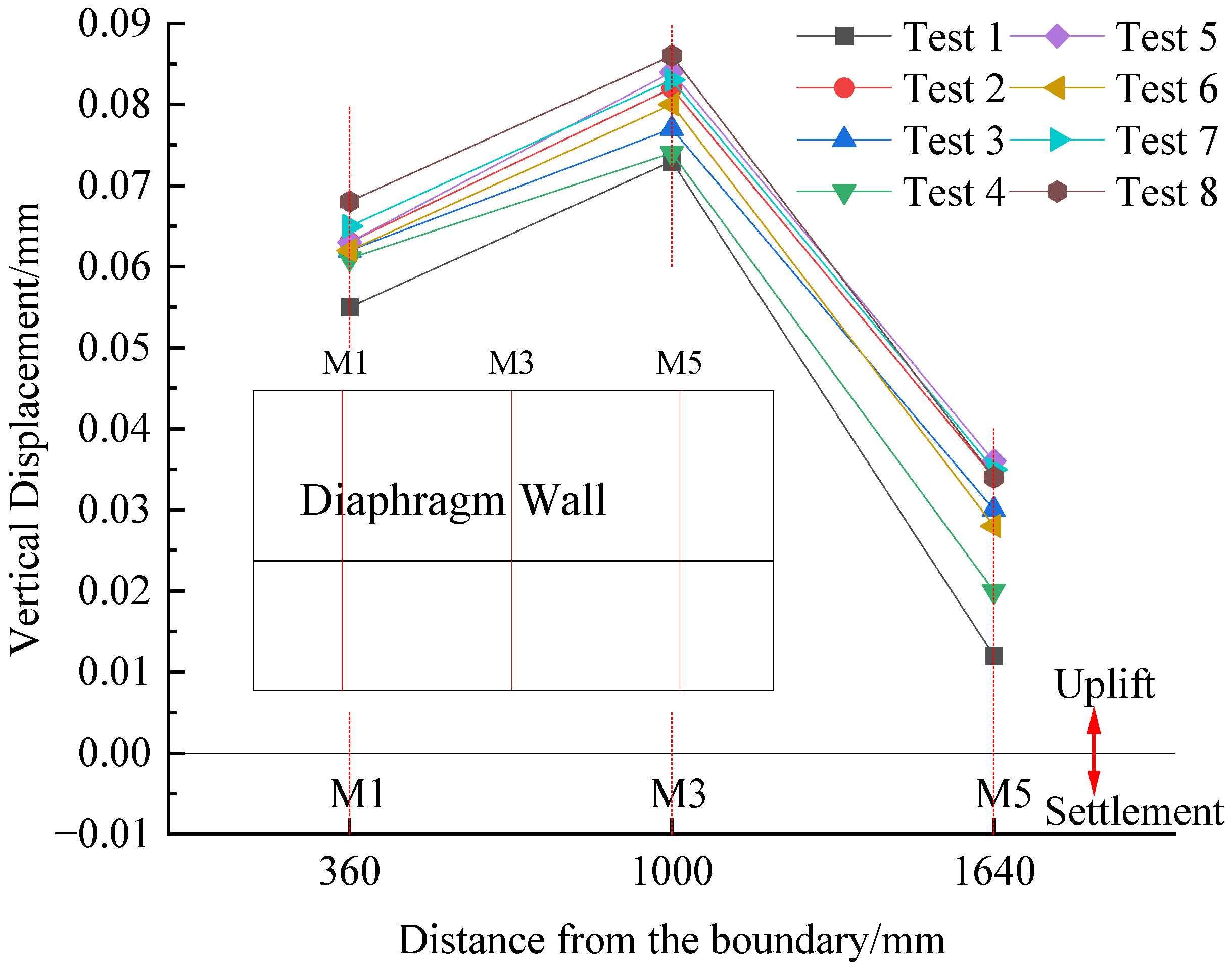
Figure 6 shows the vertical displacement variation in the diaphragm wall under different combinations of servo steel struts. As can be seen from
Figure 6, the effect of servo steel struts intensifies the vertical displacement of the diaphragm wall. In tests 2 to 8, the vertical displacement of the diaphragm wall increases by 12.3%, 5.5%, 1.4%, 15.1%, 9.6%, 13.7%, and 17.8%, respectively. This indicates that the presence of servo steel struts exacerbates the vertical uplift of the diaphragm wall. The more layers of servo steel struts are arranged and the closer they are to the surface, the greater their impact on the vertical uplift of the diaphragm wall. Overall, arranging the servo steel struts at a deeper location can not only effectively control the horizontal displacement of the diaphragm wall but also minimize their impact on the vertical uplift of the diaphragm wall.
3.3. Bending Moment of the Diaphragm Wall
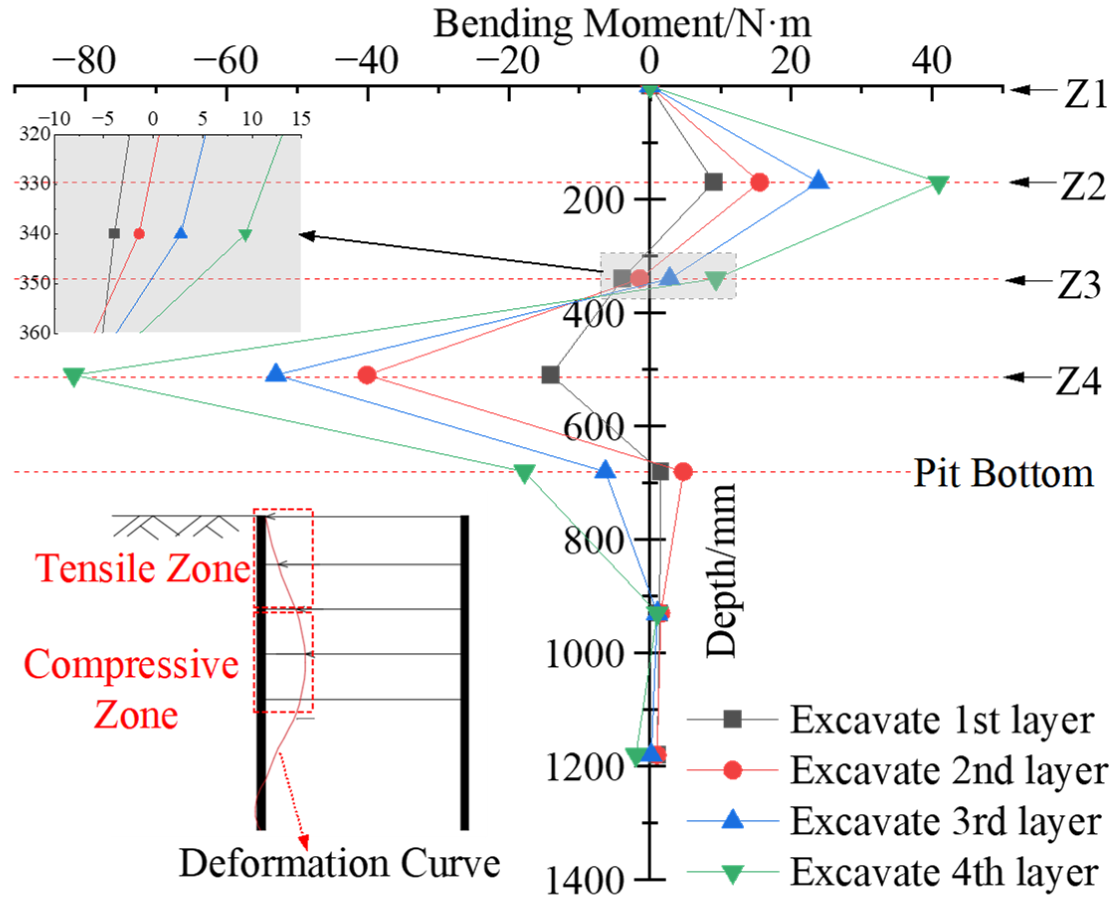
Figure 7 shows the bending moment variation in the diaphragm wall during the excavation stage of the pit. The bending moment on the wall’s back side is considered positive when tensile, and negative when compressive. The following is illustrated: (1) The bending moment of the diaphragm wall follows an “inverse S” distribution, with the inflection point located near Z3. Above the inflection point, the bending moment is positive, and below the inflection point, it is negative. This distribution pattern is consistent with the findings of Wang [
26]. (2) With the progress of the excavation, the bending moment of the diaphragm wall increases further, and the inflection point gradually moves downward. After the excavation is completed, the maximum positive bending moment is 40.880 N· m, and the maximum negative bending moment is −81.606 N· m.
Figure 8 shows the bending moment variation in the diaphragm wall under different combinations of servo steel struts. From
Figure 8, we can observe the following: (1) Under the action of servo steel struts, the negative bending moment of the diaphragm wall tends to decrease. In tests 2 to 8, the negative bending moment decreases by 10.6%, 0.04%, 2.0%, 13.1%, 3.4%, 10.5%, and 17.2%, respectively. The reason for this reduction is that after the excavation is completed, the diaphragm wall generally bends inward toward the pit, leading to a larger negative bending moment. When the servo steel struts elongate, they reduce the inward bending trend of the diaphragm wall, which in turn decreases the negative bending moment to some extent. (2) There is a difference in the positive bending moment of the diaphragm wall under different tests. In most conditions, the positive bending moment increases. Specifically, in test 2, it increases by 8.4%, in test 5 by 12.3%, in test 7 by 6.4%, and in test 8 by 19.9%. The reason for this increase is that after the excavation is completed, the diaphragm wall experiences a positive bending moment on the back side at Z2, where the wall is in tension. The elongation of the second servo steel strut increases the tensile force on the wall’s back, thereby increasing the positive bending moment. (3) In tests that do not include the action of the second servo steel struts, the positive bending moment shows a decreasing trend. Specifically, in test 3, the positive bending moment decreases by 0.03%, in test 4 by 7.0%, and in test 6 by 7.4%.
It can be seen that while servo steel struts can effectively control the horizontal displacement of the diaphragm wall, they also influence the internal force distribution of the diaphragm wall to some extent. If the axial force of the servo steel struts becomes too large, it may cause the back positive bending moment of the diaphragm wall to increase further, thereby increasing the risk of the wall buckling outward. The monitoring section in this experiment is located at the center of the excavation (between the two struts). If the monitoring section includes the strut section, the effect of the bending moment variation will be more significant. In actual engineering, it is important to pay attention to the impact of the servo loading on the bending moment of the diaphragm wall. If necessary, additional reinforcement can be applied to the diaphragm wall in the area affected by the servo struts to strengthen its bending resistance and overall stability.
3.4. Lateral Soil Pressure of the Diaphragm Wall
Before the excavation of the foundation pit, the initial values of all soil pressure gauges are set to zero. When the measured data is positive, it indicates an increase in soil pressure at that point; when the value is negative, it indicates a decrease in soil pressure at that point.
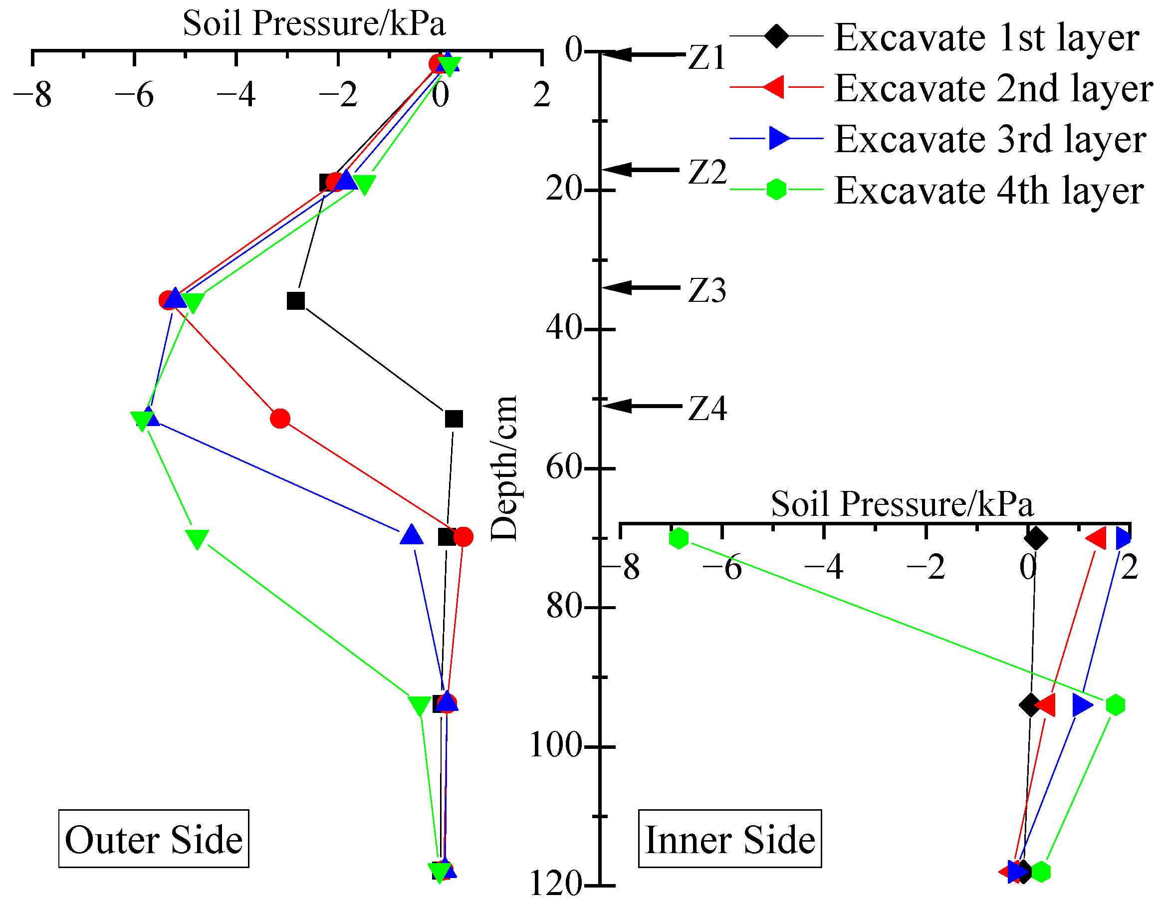
Figure 9 shows the lateral soil pressure variation on the diaphragm wall during the foundation pit excavation phase. The data on the left side of the figure represents the lateral soil pressure changes on the outer side of the diaphragm wall, while the right side shows the lateral soil pressure changes on the inner side of the diaphragm wall. The following are shown in the figure: (1) With the increase in excavation depth, the diaphragm wall undergoes inward deflection deformation, and the soil pressure on the wall gradually decreases. The largest reduction in soil pressure occurs at the wall corresponding to the excavation layer of the soil. (2) The lateral soil pressure on the inner side of the diaphragm wall shows an increasing trend. The farther the point is from the excavation surface, the smaller the impact of the excavation. However, near the excavation surface on the pit’s inner side, the soil pressure at the points shows a decreasing trend. This could be due to the fact that the points are near the pit bottom. When the fourth layer of soil is excavated down to the pit bottom, the soil stress is released, leading to a sharp decrease in the soil pressure at the pit bottom points.
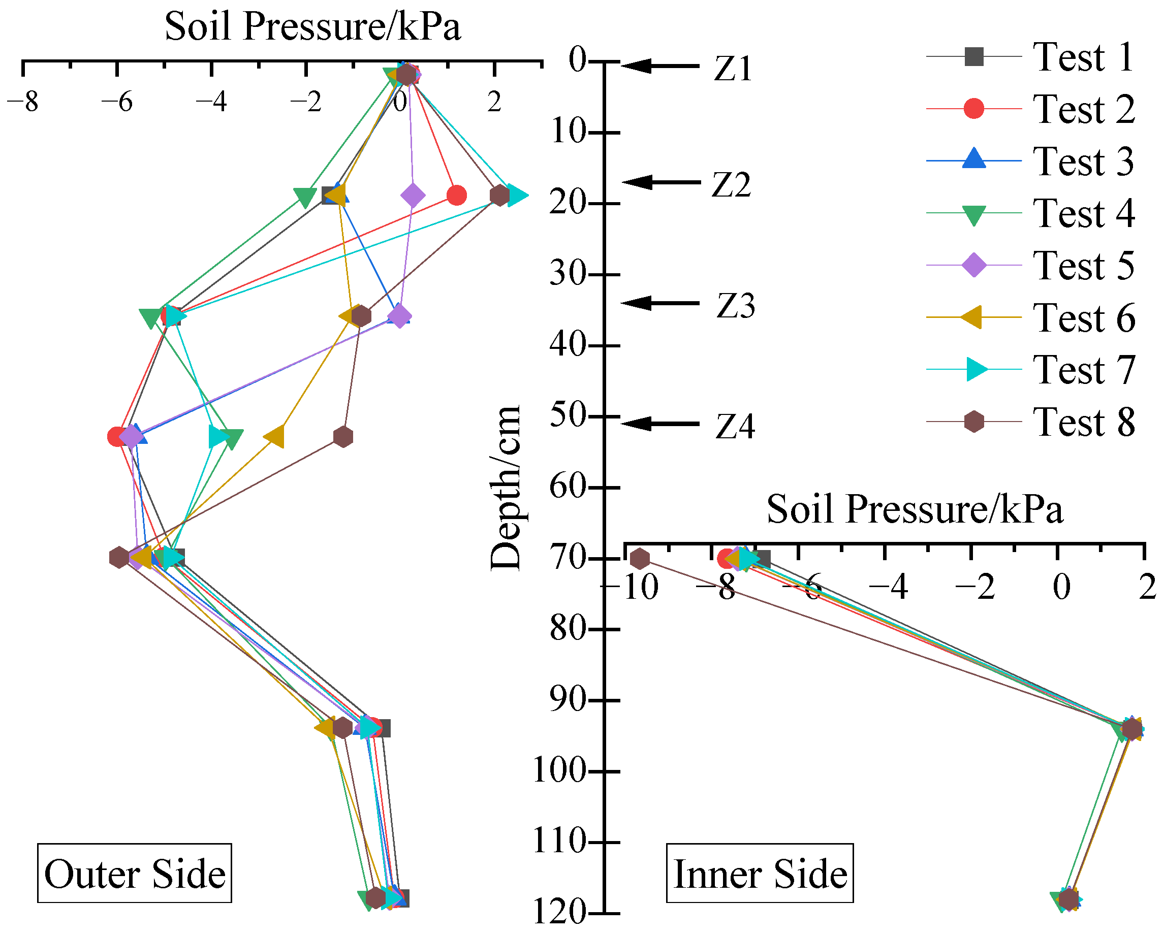
Figure 10 shows the lateral soil pressure variation on the diaphragm wall under different combinations of servo steel struts. The analysis of the figure shows the following: (1) Lateral soil pressure on the outer side of the diaphragm wall: In test 2, the soil pressure on the wall at point Z2 increased by 181%, transitioning from an active to a passive state. In test 3, the pressure at point Z3 increased by 99%. In test 4, the pressure at point Z4 increased by 39%. In test 5, the pressure at Z2 increased by 118%, and at Z3, it increased by 100%. In test 6, the pressure at Z3 increased by 79%, and at Z4, it increased by 55%. In test 7, the pressure at Z2 increased by 264%, and at Z4, it increased by 33%. In test 8, the pressure at Z2 increased by 242%, at Z3 it increased by 83%, and at Z4 it increased by 79%. From these observations, it can be concluded that the servo steel struts significantly influence the mechanical state of the soil layers [
27]. The axial force applied by the struts causes the lateral soil pressure on the wall near the struts to increase, with the pressure being most concentrated at the shallow strut points. The influence of deep strut points on the lateral soil pressure is relatively smaller. (2) Due to the force-sharing effect of the axial load, the lateral soil pressure on the inner side of the diaphragm wall generally showed a decreasing trend, with the pressure impact mainly concentrated around the pit bottom. The soil pressure at the excavation surface of the pit (measured at different points) decreased as follows for different tests: 11.4% in test 1, 5.3% in test 2, 5.1% in test 3, 8.0% in test 4, 7.8% in test 5, 4.9% in test 6, and 40.9% in test 7. The changes in soil pressure at the other points were relatively small, and the pressure dissipated and decreased as the excavation depth increased.
In the engineering projects, when using servo steel struts, the focus should not solely be on controlling the lateral displacement of the diaphragm wall. Instead, it is important to reasonably control the elongation of the struts, while also strengthening the monitoring of the soil pressure on the back of the wall to prevent safety hazards caused by the concentration of soil pressure.
3.5. Surface Settlement
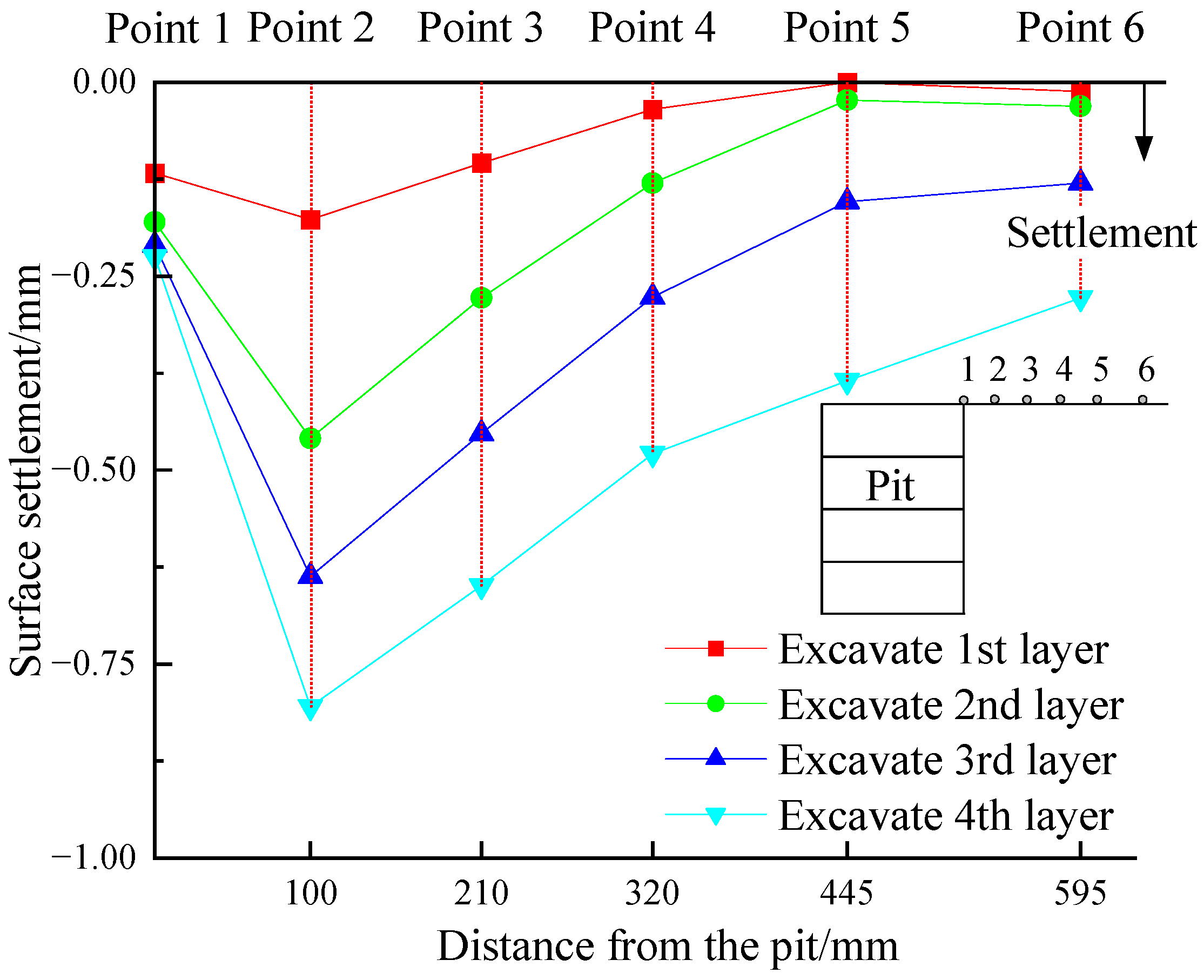
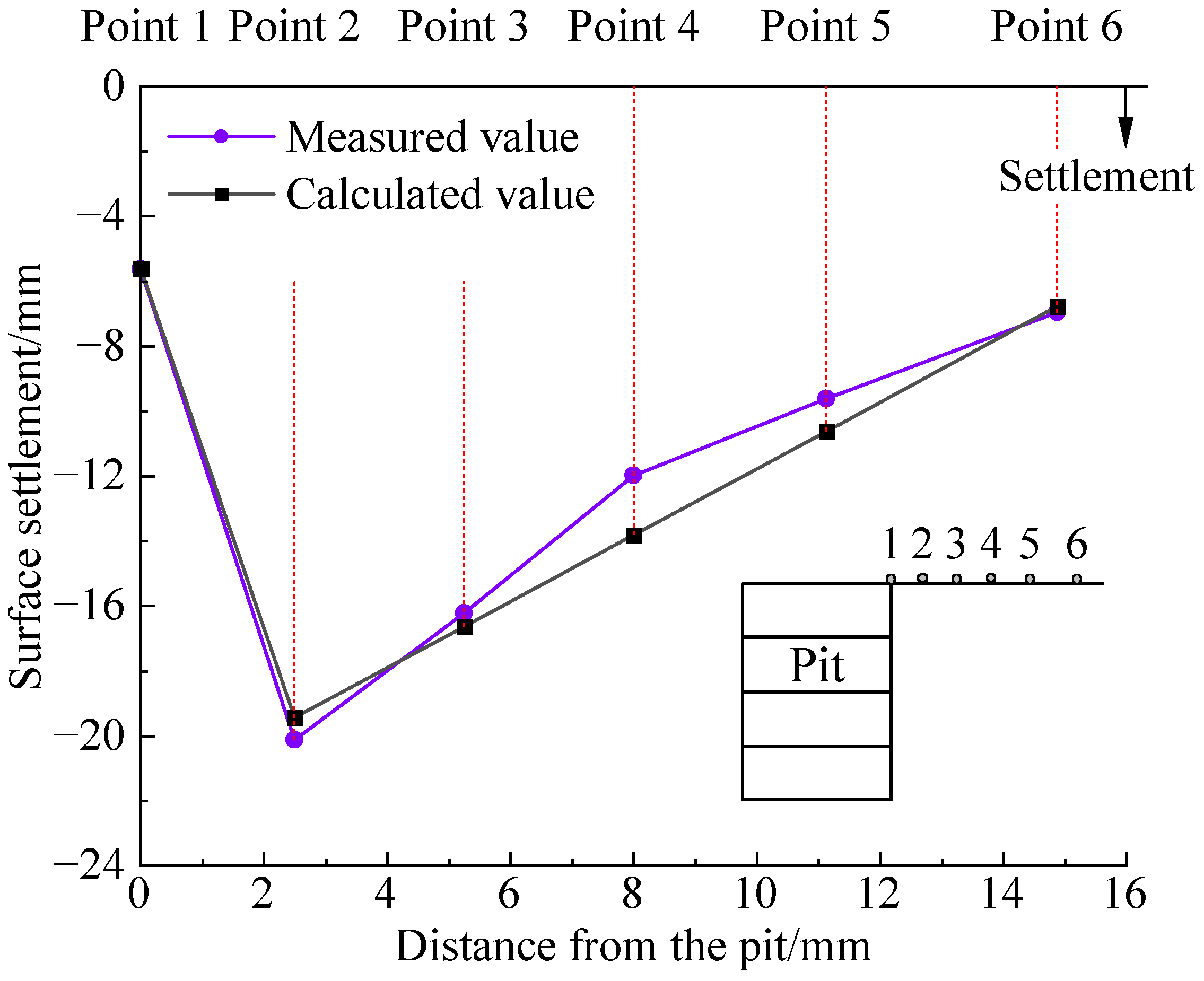
Figure 11 shows the variation in surface settlement during the excavation stage of the foundation pit. The following is shown in the figure: (1) As the excavation stage progresses, the surface settlement gradually increases, and the settlement curve overall presents a “V” shape. (2) After the excavation of the soil is completed, the maximum settlement occurs at the second point (10 cm from the foundation pit), reaching 0.805 mm, or approximately 0.012%H. The settlement at other points decreases as the distance from the foundation pit increases. (3) During the excavation of shallow soil layers, the settlement impact is mainly concentrated near the foundation pit. During the excavation of deep soil layers, the settlement impact extends to the far side of the pit.
Xu [
28] used the surface settlement theory induced by the retaining wall translation model combined with the longitudinal parabolic curve to calculate the surface settlement outside the pit caused by foundation pit excavation. The calculation formula is as follows:
In the formula, is the surface settlement at any point behind the wall (mm); w is the lateral surface settlement behind the wall (mm); x0 is the distance from the edge of the strut structure to the maximum settlement value behind the wall; d is the maximum displacement of the retaining wall (mm); A is the main influence radius; H is the excavation depth; B is the width of the foundation pit; Ed is the stiffness of the retaining wall; L is the length of the foundation pit; is the settlement impact range; and x is the horizontal distance from the foundation pit to the retaining wall.
The measured surface settlement data from the model test, scaled up according to the similarity ratio, is compared with the theoretical settlement data, as shown in
Figure 12. It can be seen that the calculated settlement curve and the measured settlement curve exhibit a generally consistent pattern.
Figure 13 shows the variation in surface settlement with different combinations of servo steel struts, and the data from
Figure 13 is summarized in
Table 5. From
Table 5, the following conclusions can be drawn: (1) Most tests can reduce surface settlement, such as tests 2, 5, 7, and 8. The surface settlement control effect is best under the full servo strut loading. When servo steel struts are arranged closer to the surface, the surface settlement control effect becomes more pronounced. (2) A small number of tests lead to increased surface settlement, such as tests 3, 4, and 6. The reason is that when the servo steel struts near the bottom of the pit extend, the wall near the surface may buckle inward due to the small stiffness and continuity of the diaphragm wall, thereby exacerbating the settlement of the surrounding soil. This shows that the impact of servo steel struts on surface settlement is not only related to their distribution throughout the depth but also closely tied to the stiffness of the diaphragm wall. (3) From the data on the range of influence of servo steel struts on surface settlement, it is evident that the more layers of servo steel struts and the deeper their arrangement, the wider the influence range.
3.6. Lateral Soil Pressure Variation Around the Pit (Horizontal)
Figure 14 shows the lateral soil pressure variation around the pit (horizontal) during the excavation stage. As illustrated in
Figure 14, (1) during the excavation stage, the lateral soil pressure around the pit decreases overall, with the maximum reduction of 3.031 kPa occurring at point 2. The change in soil pressure corresponds with the surface settlement pattern. (2) When excavating the first and second layers of soil, the change in soil pressure is mainly concentrated near the pit. After excavating the next two layers, the impact of soil unloading on the lateral soil pressure around the pit further increases.
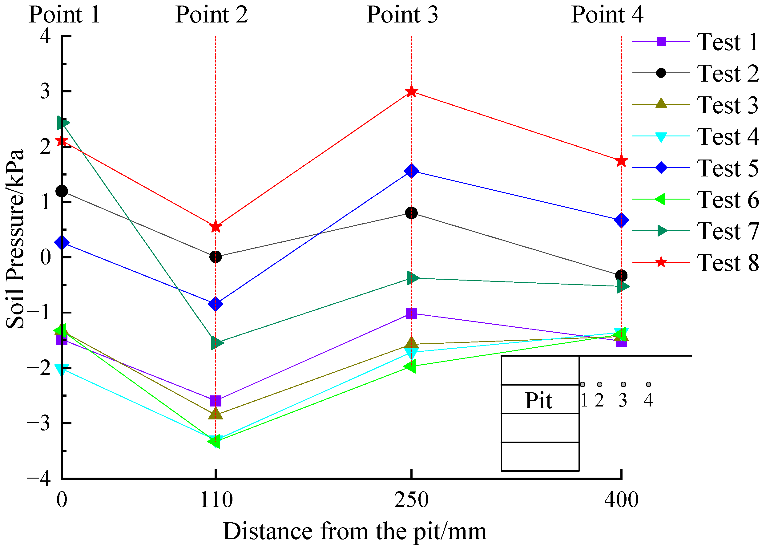
Figure 15 shows the surrounding soil pressure variation (horizontal) of the foundation pit under different combinations of servo steel struts. From
Figure 15, the following can be concluded:
(1) Single-layer servo action: In test 2, the soil pressure at the points changes significantly, as the points are at the same horizontal depth as the second strut. The soil pressures at points 1 to 4 increase by 2.679 kPa, 2.601 kPa, 1.816 kPa, and 1.181 kPa, respectively. It can be observed that as the distance between the point and the foundation pit increases, the effect of the servo loading on the surrounding soil pressure decreases; in tests 3 and 4, the surrounding soil pressure at the points shows a decreasing trend. In test 3, the maximum decrease is 0.559 kPa, while in test 4, the maximum decrease is 0.711 kPa.
(2) Multi-layer servo action: In test 5, the soil pressure at the surrounding points increases, with a maximum increase of 2.578 kPa; in test 6, the surrounding soil pressure at the points decreases, with a maximum decrease of 0.959 kPa; in test 7, the soil pressure at the surrounding points increases, with an increase of 1.044 kPa; and in test 8, the surrounding soil pressure at the points shows an increasing trend, with a maximum increase of 4.011 kPa.
It can be seen that under the action of the servo steel strut, the surrounding soil pressure of the foundation pit does not always show an increasing trend, and should be judged based on the location of the servo steel strut. When the servo steel strut extends, the surrounding soil pressure at the same horizontal depth as the servo steel strut will correspondingly increase. However, in the adjacent upper and lower regions, the continuous effect of the diaphragm wall will cause the soil to bend inward, leading to a reduction in the surrounding soil pressure. Therefore, for projects where existing structures are located next to the foundation pit, the corresponding servo steel strut loading should be applied based on the burial depth of the protected objects.
3.7. Lateral Soil Pressure Variation Around the Pit (Vertically)
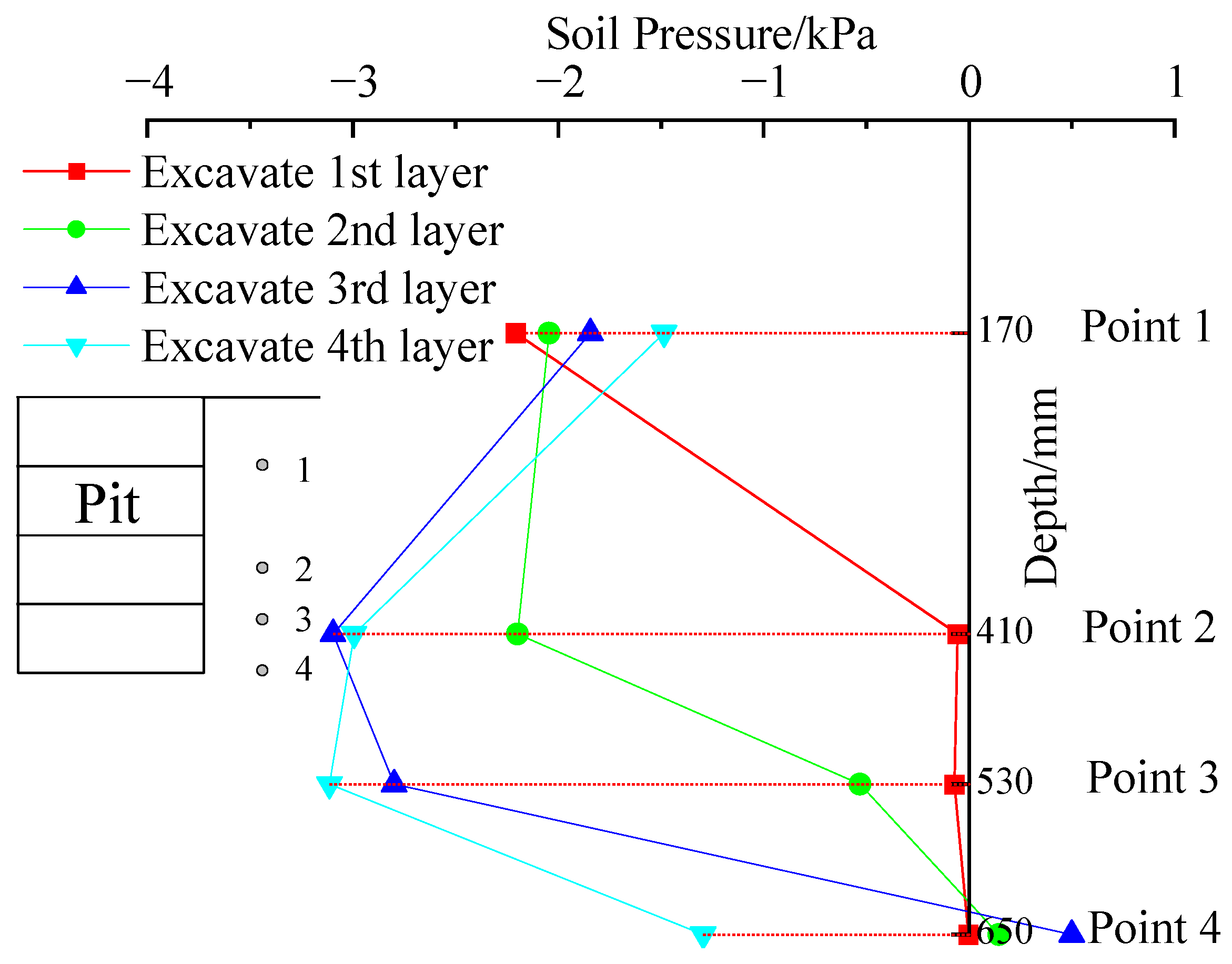
Figure 16 shows the lateral soil pressure variation around the pit (vertically) during the excavation stage. As illustrated in
Figure 16, (1) with the unloading of the pit, the lateral soil pressure arranged vertically generally decreases, transitioning from a state of at-rest soil pressure to a state of active soil pressure. The maximum reduction in lateral soil pressure around the pit at the end of excavation is 3.113 kPa (point 3). The stress distribution follows the same trend as the horizontal displacement of the diaphragm wall. (2) The lateral soil pressure at the same horizontal depth near the excavation layer is most significantly affected, with the influence decreasing as the distance from the excavated soil layer increases. Furthermore, due to the continuity of the diaphragm wall, excavation also causes an opposite effect on the lateral soil pressure at points located farther away from the excavation zone.
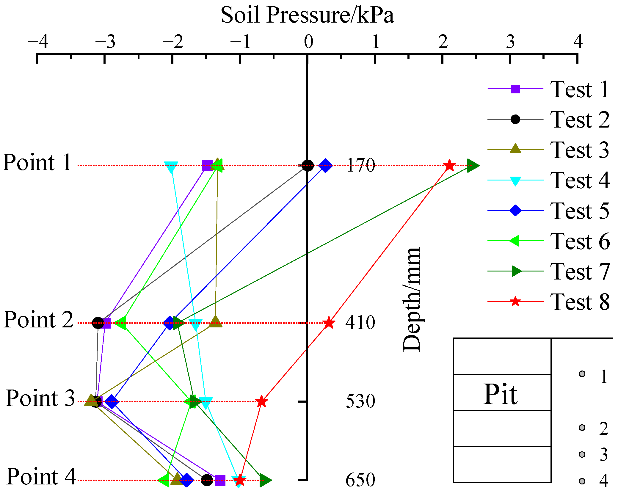
Figure 17 shows the lateral soil pressure variation around the pit (arranged vertically and influenced by horizontal soil pressure) under different combinations of servo steel struts. The data from
Figure 17 is summarized in
Table 6, and the following conclusions can be drawn: (1) The effect of adjusting a single-row servo steel strut on lateral soil pressure at the same horizontal level is the most significant; (2) servo steel struts located in the upper part of the pit have a smaller impact on deep soil pressure around the pit, but those near the bottom of the pit can influence the shallow soil pressure around the pit to a certain extent; and (3) servo steel struts arranged with gaps have a greater impact range on lateral soil pressure around the pit than those arranged continuously, with a more evenly distributed increase in soil pressure at different points.
3.8. Mechanism of Action of Servo Steel Struts
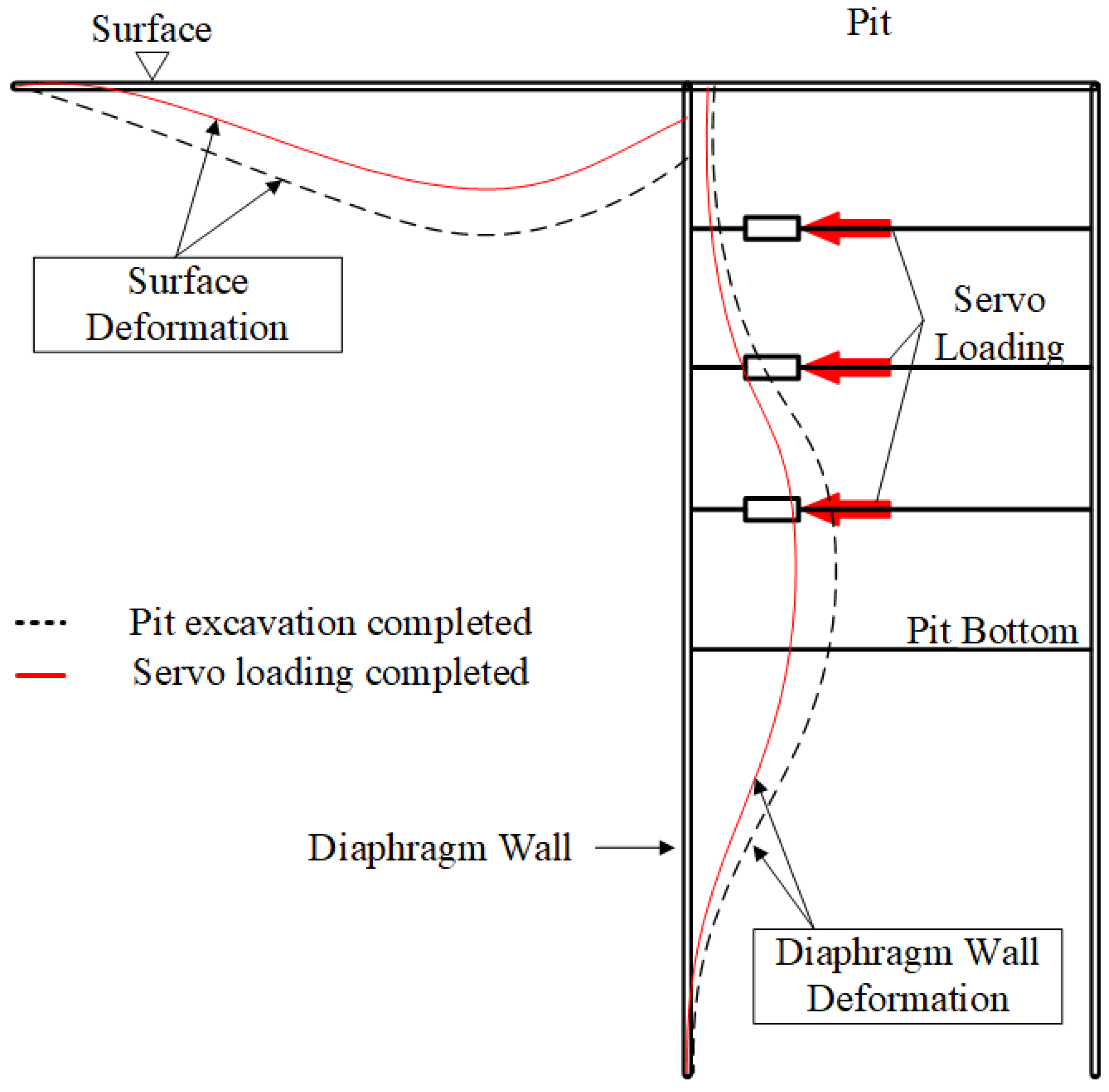
Figure 18 shows the impact of excavation unloading on the foundation pit and the mechanism of control of servo steel strut loading based on the results of model tests. During deep foundation pit excavation unloading, the diaphragm wall moves inward into the pit, and the displacement continuously increases. This change alters the stress field of the surrounding soil, resulting in increased surface settlement and deformation, which has an adverse effect on the foundation pit and surrounding structures. Under the loading effect of the servo steel strut, the diaphragm wall moves outward, and the displacement is controlled. Since the diaphragm wall and the surrounding soil are interconnected, this further compensates for the loss of stress in the surrounding soil, thus reducing surface settlement and deformation, and playing a certain role in controlling the deformation of the foundation pit and surrounding structures.
4. Conclusions
To effectively reduce the deformation of the excavation pit caused by unloading during soil excavation, based on indoor model tests, the variations in deformation, bending moment of the diaphragm wall, ground surface settlement, and soil pressure around the pit were analyzed during both the excavation phase and the active control phase of the servo steel struts. Furthermore, the mechanism by which servo steel struts control pit deformation was elucidated. The main contributions of this paper are summarized as follows:
(1) During excavation unloading, the diaphragm wall exhibits vertical deformation characterized by upward bulging, accompanied by an increased bending moment displaying a reverse S-shaped distribution. Concurrently, earth pressure acting on the wall’s rear face progressively diminishes, while surrounding soil pressure attenuates with increasing distance from the excavation. Surface settlement intensifies gradually; shallow soil unloading primarily localizes settlement near the excavation zone, whereas deep soil unloading induces settlement effects extending farther afield. Furthermore, servo control requires judicious management: excessive strut expansion may induce overcompensation, precipitating adverse deformation modes. Consequently, field applications should integrate real-time monitoring feedback systems with incremental servo adjustments.
(2) Prioritizing servo steel strut installations at the foundation pit bottom and increasing strut layers optimizes placement, significantly improving diaphragm wall displacement control. Struts in shallow strata effectively mitigate surface settlement, whereas those in deeper strata optimally restrain maximum horizontal wall displacement. Crucially, the efficacy of servo steel struts in controlling both wall displacement and surface settlement depends not only on their depthwise distribution but also significantly on diaphragm wall stiffness. For practical implementation, servo-controlled struts should be concentrated near the foundation pit bottom to constrain peak horizontal deformations, while shallow-layer deployments target settlement reduction. In projects adjacent to deformation-sensitive structures (e.g., subways, pipelines, historical buildings), servo systems should be configured for independent multi-point control based on predefined deformation thresholds.
(3) The servo system dynamically adjusts strut displacements, triggering the redistribution of internal forces within the diaphragm wall and localized stress fields in surrounding soils. This active control mechanism reduces negative bending moments while potentially increasing positive bending moments in the wall. Concurrently, soil pressure behind the wall and adjacent soil pressures rise, exhibiting attenuation with increasing distance from the excavation. Practically, servo strut activation compensates for excavation-induced soil pressure loss. Regarding structural safety, design considerations must address servo-induced positive bending moment amplification—particularly at strut connections—through localized reinforcement or increased wall thickness to mitigate outward buckling risks and ensure safety margins.
Author Contributions
Conceptualization, methodology, supervision, resources, Z.W. and G.W.; data curation, formal analysis, X.W., P.W. and H.L.; investigation, K.C. and S.Y.; writing—original draft preparation, W.F.; writing—review and editing, W.F. and K.C.; project administration, Z.W. All authors have read and agreed to the published version of the manuscript.
Funding
This research was funded by Gang Wei through the Basic Public Welfare Research Projects of Zhejiang Province, grant number LGF22E080012.
Data Availability Statement
The data that support the findings of this study is available from the corresponding author upon reasonable request.
Conflicts of Interest
The authors declare no conflicts of interest.
References
- Houhou, M.N.; Emeriault, F.; Belounar, A. Three-Dimensional Numerical Back-Analysis of a Monitored Deep Excavation Retained by Strutted Diaphragm Walls. Tunn. Undergr. Space Technol. 2019, 83, 153–164. [Google Scholar] [CrossRef]
- Shi, J.; Ng, C.W.W.; Chen, Y. Three-Dimensional Numerical Parametric Study of the Influence of Basement Excavation on Existing Tunnel. Comput. Geotech. 2015, 63, 146–158. [Google Scholar] [CrossRef]
- Li, M.-G.; Zhang, Z.-J.; Chen, J.-J.; Wang, J.-H.; Xu, A.-J. Zoned and Staged Construction of an Underground Complex in Shanghai Soft Clay. Tunn. Undergr. Space Technol. 2017, 67, 187–200. [Google Scholar] [CrossRef]
- Mangushev, R.A.; Osokin, A.I.; Garnyk, L.V. Experience in Preserving Adjacent Buildings during Excavation of Large Foundation Pits under Conditions of Dense Development. Soil Mech. Found. Eng. 2016, 53, 291–297. [Google Scholar] [CrossRef]
- Ng, C.W.W.; Wei, J.; Poulos, H.; Liu, H. Effects of Multipropped Excavation on an Adjacent Floating Pile. J. Geotech. Geoenviron. Eng. 2017, 143, 4017021. [Google Scholar] [CrossRef]
- Liu, B.; Zhang, D.-W.; Yang, C.; Zhang, Q.-B. Long-Term Performance of Metro Tunnels Induced by Adjacent Large Deep Excavation and Protective Measures in Nanjing Silty Clay. Tunn. Undergr. Space Technol. 2020, 95, 103147. [Google Scholar] [CrossRef]
- Shi, J.; Wei, J.; Ng, C.W.W.; Lu, H. Stress Transfer Mechanisms and Settlement of a Floating Pile Due to Adjacent Multi-Propped Deep Excavation in Dry Sand. Comput. Geotech. 2019, 116, 103216. [Google Scholar] [CrossRef]
- Orazalin, Z.Y.; Whittle, A.J.; Olsen, M.B. Three-Dimensional Analyses of Excavation Support System for the Stata Center Basement on the MIT Campus. J. Geotech. Geoenviron. Eng. 2015, 141, 5015001. [Google Scholar] [CrossRef]
- Jamsawang, P.; Jamnam, S.; Jongpradist, P.; Tanseng, P.; Horpibulsuk, S. Numerical Analysis of Lateral Movements and Strut Forces in Deep Cement Mixing Walls with Top-down Construction in Soft Clay. Comput. Geotech. 2017, 88, 174–181. [Google Scholar] [CrossRef]
- Tan, Y.; Wei, B.; Lu, Y.; Yang, B. Is Basal Reinforcement Essential for Long and Narrow Subway Excavation Bottoming out in Shanghai Soft Clay? J. Geotech. Geoenviron. Eng. 2019, 145, 5019002. [Google Scholar] [CrossRef]
- Niu, J.; Li, Z.; Feng, C.; Wang, B.; Chen, K. Combined Support System and Calculation Model for Deep Foundation Pits in Fill Soil Areas. Arab. J. Geosci. 2020, 13, 347. [Google Scholar] [CrossRef]
- Han, M.; Li, Z.; Mei, G.; Bao, X.; Jia, J.; Liu, L. Deformation Characteristics for Subway Excavation in Soft Soil and Temperature Correction Method in Strut Force. Arab. J. Sci. Eng. 2023, 48, 4357–4380. [Google Scholar] [CrossRef]
- Goh, A.T.C.; Zhang, F.; Zhang, W.; Chew, O.Y.S. Assessment of Strut Forces for Braced Excavation in Clays from Numerical Analysis and Field Measurements. Comput. Geotech. 2017, 86, 141–149. [Google Scholar] [CrossRef]
- Chen, B.; Yan, T.; Song, D.; Luo, R.; Zhang, G. Experimental Investigations on a Deep Excavation Support System with Adjustable Strut Length. Tunn. Undergr. Space Technol. 2021, 115, 104046. [Google Scholar] [CrossRef]
- Di, H.; Guo, H.; Zhou, S.; Chen, J.; Wen, L. Investigation of the Axial Force Compensation and Deformation Control Effect of Servo Steel Struts in a Deep Foundation Pit Excavation in Soft Clay. Adv. Civ. Eng. 2019, 2019, 5476354. [Google Scholar] [CrossRef]
- Li, M.-G.; Demeijer, O.; Chen, J.-J. Effectiveness of Servo Struts in Controlling Excavation-Induced Wall Deflection and Ground Settlement. Acta Geotech. 2020, 15, 2575–2590. [Google Scholar] [CrossRef]
- Li, M.-G.; Xiao, Q.-Z.; Liu, N.-W.; Chen, J.-J. Predicting Wall Deflections for Deep Excavations with Servo Struts in Soft Clay. J. Geotech. Geoenviron. Eng. 2024, 150, 04023124. [Google Scholar] [CrossRef]
- Huang, B.; Li, M.; Hou, Y.; Chen, J. Effect of auto-compensating steel struts on stress and deformation behaviors of supporting structures. Rock Soil Mech. 2018, 39, 359–365. [Google Scholar] [CrossRef]
- Jin, Y.; Di, H.; Zhou, S.; Liu, H.; Wu, D.; Guo, H. Effects of Active Axial Force Adjustment of Struts on Support System during Pit Excavation: Experimental Study. J. Geotech. Geoenviron. Eng. 2024, 150, 04024027. [Google Scholar] [CrossRef]
- Di, H.; Jin, Y.; Zhou, S.; Zhang, X.; Wu, D.; Guo, H. Experimental Study on the Adjustments of Servo Steel Struts in Deep Excavations. Acta Geotech. 2023, 18, 6615–6629. [Google Scholar] [CrossRef]
- Sun, J.; Bai, Y. Study on the setting method of steel supporting axial force servo system for subway foundation pit. Chin. J. Undergr. Space Eng. 2019, 1, 195–204. [Google Scholar]
- Kong, Y.; Wan, Q.; Ding, H.; Zhou, Y.; Huang, Z.; Xu, C. Optimal Design of Double-Braced Supporting Structure in Asymmetric Excavation. Tunn. Constr. 2023, 43, 356–364. [Google Scholar]
- Hu, J. Research on the Influence of Excavation of Deep Foundation Pit to Adjacent Existing High—Speed Railway Bridge Pile Foundations Stability. J. Railw. Eng. Soc. 2017, 34, 12–17, 22. [Google Scholar]
- Xiao, X.; Li, M.; Chen, J.; Xia, X. Vertical deformation mechanism of diaphragm wall due to unloading in deep excavation. J. Shanghai Jiaotong Univ. 2018, 52, 1552–1558. [Google Scholar] [CrossRef]
- Xiao, X.; Zhang, Y.; Li, M.; Wang, J. Responses of the Strata and Supporting System to Dewatering in Deep Excavations. J. Shanghai Jiaotong Univ. 2017, 22, 705–711. [Google Scholar] [CrossRef]
- Wang, L. Study on Stress Mechanism and Optimal Design of Internal Support Axial Force for Metro Deep Foundation. Master’s Thesis, Changan University, Xi’an, China, 2018. [Google Scholar]
- Sun, J.; Cao, H.; Wang, Z. In-situ Test Study on the Evolution Law of Mechanical Field of Soft Soil Foundation Excavation Under Axial Force. Constr. Technol. 2023, 52, 32–40. [Google Scholar]
- Xu, B. Analysis on Effect of Deep Foundation Pit Excavation of Metro Station in Soft Soil Area of Hangzhou. Master’s Thesis, Zhejiang University of Technology, Hangzhou, China, 2017. [Google Scholar]
Figure 2.
Layout of test points (unit: mm).
Figure 2.
Layout of test points (unit: mm).
Figure 3.
Horizontal displacement variation in diaphragm wall.
Figure 3.
Horizontal displacement variation in diaphragm wall.
Figure 4.
Horizontal displacement variation in diaphragm wall under different combinations of servo steel struts.
Figure 4.
Horizontal displacement variation in diaphragm wall under different combinations of servo steel struts.
Figure 5.
Vertical displacement variation in diaphragm wall.
Figure 5.
Vertical displacement variation in diaphragm wall.
Figure 6.
Vertical displacement variation in diaphragm wall under different combinations of servo steel struts.
Figure 6.
Vertical displacement variation in diaphragm wall under different combinations of servo steel struts.
Figure 7.
Bending moment variation in diaphragm wall.
Figure 7.
Bending moment variation in diaphragm wall.
Figure 8.
Bending moment variation in diagram wall under different combinations of servo steel struts.
Figure 8.
Bending moment variation in diagram wall under different combinations of servo steel struts.
Figure 9.
Lateral soil pressure variation on diaphragm wall.
Figure 9.
Lateral soil pressure variation on diaphragm wall.
Figure 10.
Lateral soil pressure variation in diaphragm wall under different combinations of servo steel struts.
Figure 10.
Lateral soil pressure variation in diaphragm wall under different combinations of servo steel struts.
Figure 11.
Surface settlement.
Figure 11.
Surface settlement.
Figure 12.
Comparison of surface settlement.
Figure 12.
Comparison of surface settlement.
Figure 13.
Surface settlement variation under different combinations of servo steel struts.
Figure 13.
Surface settlement variation under different combinations of servo steel struts.
Figure 14.
Soil pressure variation around the pit (horizontal).
Figure 14.
Soil pressure variation around the pit (horizontal).
Figure 15.
Soil pressure variation around the pit (horizontal) under different combinations of servo steel struts.
Figure 15.
Soil pressure variation around the pit (horizontal) under different combinations of servo steel struts.
Figure 16.
Variation in soil pressure around the pit (vertical).
Figure 16.
Variation in soil pressure around the pit (vertical).
Figure 17.
Soil pressure variation around the pit (vertical) under different combinations of servo steel struts.
Figure 17.
Soil pressure variation around the pit (vertical) under different combinations of servo steel struts.
Figure 18.
Mechanism diagram of servo steel strut control action.
Figure 18.
Mechanism diagram of servo steel strut control action.
Table 1.
Material parameters.
Table 1.
Material parameters.
| Material | γ/(kN/m3) | E/GPa | Poisson’s Ratio | Direct Shear φ/(°) | c/kPa |
|---|
| Dry sand | 18 | 0.03 | 0.32 | 35 | 0 |
Aluminum alloy
(6061 model) | 28 | 70 | 0.33 | − | − |
Table 2.
Test monitoring project.
Table 2.
Test monitoring project.
| Monitoring Number | Monitoring Content | Measuring Instrument | Measuring Range | Accuracy | Layout Plan |
|---|
| 1 | Horizontal displacement of the foundation wall | BL-30NZ Laser Displacement Measuring Sensor(Boyi Jingke Technology Co., Ltd. Shenzhen, China) | 30 mm | 0.03 mm | Five points arranged in the middle section of the foundation pit |
| 2 | Vertical displacement of the foundation wall | Digital Micrometer(Jingru Liangyi Technology Co., Ltd. Dongguan, China) | 0~12.7 mm | 0.001 mm | One point arranged in the middle section of the foundation pit |
| 3 | Bending moment of the foundation wall | BE120-5AA Strain Gauge(Shenzhen Zhuoye Technology Co., Ltd. Shenzhen, China) | —— | 2% | Seven points arranged in the middle section of the foundation pit |
| 4 | Lateral pressure on the foundation wall | YLH-50K Soil Pressure Cell(Nanjing Danmo Electronic Technology Co., Ltd. Nanjing, China)
| 50 kPa | 0.05% | Ten points arranged in the middle section of the foundation pit |
| 5 | Surface settlement | Digital Micrometer | 0~12.7 mm | 0.001 mm | Six points arranged on the ground surface of the middle section of the foundation pit |
| 6 | Soil pressure
around the pit | YLH-50K Soil Pressure Cell | 50 kPa | 0.05% | Six points arranged around the perimeter of the foundation pit in the middle section |
Table 3.
Test condition.
| Test | Excavation | Servo Strut Loading Conditions |
|---|
| 1 | Excavate the 1st layer of soil to −17 cm
Excavate the 2nd layer of soil to −34 cm
Excavate the 3rd layer of soil to −51 cm
Excavate the 4th layer of soil to −68 cm | No Loading |
| 2 | 2nd Servo Steel Strut Loading |
| 3 | 3rd Servo Steel Strut Loading |
| 4 | 4th Servo Steel Strut Loading |
| 5 | 2nd and 3rd Servo Steel Strut Loading |
| 6 | 3rd and 4th Servo Steel Strut Loading |
| 7 | 2nd and 4th Servo Steel Strut Loading |
| 8 | 2nd, 3rd, and 4th Servo Steel Strut Loading |
Table 4.
Horizontal displacement control statistics for enclosure structures.
Table 4.
Horizontal displacement control statistics for enclosure structures.
| Test | Servo Strut Loading Conditions | Maximum Horizontal Displacement of the Diaphragm Wall/mm | Horizontal Displacement Control Value/mm | Control Effect |
|---|
| 1 | No Loading | 1.88 | —— | —— |
| 2 | 2nd Servo Strut Loading | 1.94 | −0.06 | −3.0% |
| 3 | 3rd Servo Strut Loading | 1.77 | 0.11 | 6.0% |
| 4 | 4th Servo Strut Loading | 1.37 | 0.51 | 27.3% |
| 5 | 2nd and 3rd Servo Strut Loading | 1.79 | 0.09 | 4.8% |
| 6 | 3rd and 4th Servo Strut Loading | 1.14 | 0.74 | 39.5% |
| 7 | 2nd and 4th Servo Strut Loading | 1.47 | 0.41 | 21.8% |
| 8 | 2nd, 3rd, and 4th Servo Strut Loading | 1.20 | 0.68 | 36.4% |
Table 5.
Surface settlement.
Table 5.
Surface settlement.
| Test | Servo Strut Loading Conditions | Surface Settlement Variation
(Comparison with Test Condition 1) | Impact Range |
|---|
| 1 | No Loading | —— | —— |
| 2 | 2nd Strut Loading | −10.3% | 0.367 H |
| 3 | 3rd Strut Loading | +1.6% | 0.370 H |
| 4 | 4th Strut Loading | +7.7% | 0.603 H |
| 5 | 2nd and 3rd Strut Loading | −15.1% | 0.640 H |
| 6 | 3rd and 4th Strut Loading | +4.7% | 0.662 H |
| 7 | 2nd and 4th Strut Loading | −14.2% | 0.471 H |
| 8 | 2nd, 3rd, and 4th Strut Loading | −15.3% | 0.809 H |
Table 6.
Soil pressure variation around the pit (vertical).
Table 6.
Soil pressure variation around the pit (vertical).
| Test | Servo Strut Loading Conditions | Variation in Soil Pressure/kPa |
|---|
| Point 1 | Point 2 | Point 3 | Point 4 |
|---|
| 1 | No Loading | —— | —— | —— | —— |
| 2 | 2nd Strut Loading | +1.49 | −0.10 | −0.02 | −0.19 |
| 3 | 3rd Strut Loading | +0.16 | +1.63 | −0.09 | −0.63 |
| 4 | 4th Strut Loading | −0.53 | +1.34 | +1.61 | +0.28 |
| 5 | 2nd and 3rd Strut Loading | +1.75 | +0.96 | +0.22 | −0.49 |
| 6 | 3rd and 4th Strut Loading | +0.16 | +0.24 | +1.39 | −0.81 |
| 7 | 2nd and 4th Strut Loading | +3.92 | +1.07 | +1.44 | +0.65 |
| 8 | 2nd, 3rd, and 4th Strut Loading | +3.59 | +3.32 | +2.44 | +0.30 |
| Disclaimer/Publisher’s Note: The statements, opinions and data contained in all publications are solely those of the individual author(s) and contributor(s) and not of MDPI and/or the editor(s). MDPI and/or the editor(s) disclaim responsibility for any injury to people or property resulting from any ideas, methods, instructions or products referred to in the content. |
© 2025 by the authors. Licensee MDPI, Basel, Switzerland. This article is an open access article distributed under the terms and conditions of the Creative Commons Attribution (CC BY) license (https://creativecommons.org/licenses/by/4.0/).


