Article

Numerical Study on Shear-Oriented Parameters in RC Beams with Openings Reinforced by Fe-SMA Rebars

1
Department of Civil Engineering, American University of Sharjah, Sharjah P.O. Box 26666, United Arab Emirates
2
Structural Engineering Department, Faculty of Engineering, Tanta University, Tanta P.O. Box 31733, Egypt
3
Energy, Water, and Sustainable Environment Research Center, American University of Sharjah, Sharjah P.O. Box 26666, United Arab Emirates
*
Author to whom correspondence should be addressed.
Buildings 2025, 15(12), 2028; https://doi.org/10.3390/buildings15122028
Submission received: 16 May 2025 / Revised: 2 June 2025 / Accepted: 10 June 2025 / Published: 12 June 2025
(This article belongs to the Special Issue Strengthening and Rehabilitation of Structures or Buildings)

Abstract

Reinforced concrete (RC) beams with openings in shear spans exhibited a significantly reduced structural performance due to disruptions in load transfer mechanisms. This numerical study investigated the influence of pre-stressed iron-based Shape Memory Alloy (Fe-SMA) rebars on the behavior of RC beams with web openings, focusing on the effect of shear-oriented design parameters, including the stirrup spacing, stirrup diameter, and horizontal reinforcement around the opening. A nonlinear finite element analysis (NLFEA) was conducted using ABAQUS/CAE software 2020 to simulate the response of RC beams under these conditions. The results showed that the presence of web openings in RC beams reduced the ultimate load capacity and stiffness. However, the pre-stressed Fe-SMA reinforcement effectively mitigated these adverse effects, restoring much of the solid beam’s performance. Among the studied parameters, reducing the stirrup spacing significantly improved the load-bearing capacity, with the smallest spacing (100 mm) restoring 86% of the solid beam’s ultimate load. Increasing the Fe-SMA stirrup diameter further enhanced performance, with T16 stirrups recovering 92% of the solid beam’s ultimate load capacity. The most substantial improvement occurred when horizontal reinforcement was introduced, particularly with T16 stirrups, achieving a 95% load recovery, nearly matching the solid RC beam structural performance. These findings demonstrated the promising potential of pre-stressed Fe-SMA reinforcement as a viable solution for restoring the structural strength of RC beams with web openings.

1. Introduction

In modern structural design, reinforced concrete (RC) beams often incorporate openings to accommodate essential utilities such as pipes, ducts, and cables in buildings, bridges, and tunnels. While these openings are crucial for functional integration, they introduce significant structural challenges that demand careful attention during the design process. Openings can lead to stress concentrations, resulting in localized cracking that may propagate and weaken the RC beam over time [1,2]. Additionally, these modifications complicate the construction process, requiring extra reinforcement and increasing both costs and time [3]. The presence of openings can also reduce the stiffness and load-carrying capacity of the beam, particularly in the shear zone, and exacerbate deflection and vibration issues, potentially affecting the overall safety and comfort of the structure [4,5,6]. Recent studies on geopolymer concrete beams reinforced with glass fibers have also highlighted the need for material innovations to improve shear behavior [7]. Moreover, the openings may compromise the fire resistance of the beams by disrupting the concrete cover that protects the reinforcement, necessitating specialized thermal design strategies to ensure an adequate performance under elevated temperatures [8,9,10]. The design of such RC beams is further complicated by the challenges of predicting their behavior accurately [11]. Furthermore, openings can negatively impact beam–column connections, especially in seismic regions, where the reliability of these connections is critical for maintaining structural performance during an earthquake [12]. A comprehensive dynamic assessment, encompassing the behavior of beams, columns, and their connections, as well as the influence of soil–structure interactions, is crucial to ensuring a reliable seismic performance [13,14,15,16,17]. These complicated issues highlight the importance of a thorough analysis and careful design considerations to mitigate the adverse effects of openings on RC beams.
Several advanced solutions have been developed and implemented to address the abovementioned challenges of RC beams with openings. The strategic placement and size optimization of openings could minimize their impact by positioning them in less critical areas and limiting their dimensions [18]. Complementing this approach, reinforcement techniques, such as adding additional rebars or using advanced materials such as fiber-reinforced polymers (FRPs) [1,19,20,21,22] and Shape Memory Alloys (SMAs) [23] around the openings, help redistribute stresses and prevent cracking. Sustainability considerations are increasingly integral to modern design practices, promoting the use of green concrete, i.e., [24,25,26], fiber-reinforced geopolymer composites [7,27], eco-friendly FRP products, i.e., [28,29,30,31,32], and durable Fe-SMA, i.e., [33,34], particularly with an enhanced corrosion resistance through alloy optimization [35], materials to reduce environmental impacts while enhancing structural performance. Building on these reinforcement strategies, innovative construction methods, such as the use of precast concrete elements with pre-designed openings and post-tensioning, could enhance the precision and compensate for strength losses due to the presence of web openings [36]. In addition, advanced analytical tools like the finite element analysis (FEA) provide more accurate predictions of stress distribution, enabling more effective design modifications [37,38]. Moreover, the incorporation of high-performance materials, including high-strength concrete and hybrid reinforcements, further strengthens the RC beam and enhances durability [39,40]. Recent findings also suggest that graphene derivatives and dune sand can synergistically enhance the mechanical performance and flexural response of sustainable cementitious systems [41,42]. In seismic regions, enhancing ductility and implementing retrofitting techniques, such as FRP wrapping or SMA rebars, ensures that beam–column connections remain resilient [43,44]. Together, these solutions form a comprehensive framework for mitigating the structural issues caused by openings in RC beams, ensuring their performance in diverse applications.
One promising solution to enhance the shear capacity of RC beams with web openings in shear zones is the use of pre-stressed Shape Memory Alloy (SMA) rebars, particularly iron-based SMAs (Fe-SMA) [45]. These advanced materials offer unique properties, such as the ability to undergo large, recoverable deformations and the ability to return to a pre-defined shape upon heating, which can be utilized to improve the structural performance of RC beams [46,47]. When pre-stressed Fe-SMA rebars are integrated into the shear zones of RC beams with openings, they actively contribute to closing and stabilizing cracks that may develop due to stress concentrations, thereby enhancing the RC beam’s overall shear capacity. The pre-stressing effect of the SMA bars not only helps in delaying crack initiation but also in redistributing the internal stresses more effectively, reducing the likelihood of catastrophic failure [48,49]. Furthermore, the use of Fe-SMA rebars could significantly improve the beam’s resilience under dynamic loading conditions, such as during seismic events, by providing additional energy dissipation and improving ductility. This innovative approach has shown great potential in recent studies, making it a highly effective solution for addressing the challenges posed by openings in RC beams, particularly in critical shear zones.
Structural behavior is currently investigated through three primary approaches: experimental testing, analytical modeling, and computational methods, such as numerical simulations and machine learning, i.e., [50,51,52,53]. Numerical and analytical techniques have become increasingly dominant, offering accurate predictions with reduced time and resource demands compared to traditional experimental studies. Building on this trend, this study aimed to offer thorough insights, numerical data, and practical guidelines for the effective application of Fe-SMA rebars in reinforced concrete (RC) beams with web openings located in shear zones.
To address a notable gap in the existing literature, this study focuses on enhancing the structural performance in RC beams with web openings, an area not thoroughly explored to date. In this study, using ABAQUS software [54], a detailed numerical investigation was performed on RC beams incorporating pre-stressed Fe-SMA reinforcements. Prior research has examined the role of Fe-SMA stirrups in improving shear behavior, particularly through activation-based confinement and variations in stirrup spacing [55,56]. These studies demonstrated enhancements in shear strength, crack control, and stiffness and proposed numerical models capable of capturing such behaviors. However, they primarily focused on conventional RC beam configurations without structural discontinuities.
Although a few studies have investigated the Fe-SMA in shear-related applications, none have specifically addressed its performance in beams with web openings. This study fills that gap by exploring the previously unexamined use of the Fe-SMA in such configurations, offering new insights into its potential for complex shear applications. This analysis focuses on critical shear-related parameters, including the stirrup spacing, the stirrup diameter, and the presence of horizontal reinforcement around the openings. This study was carried out in two phases: First, the model validation was performed using experimental data from Shahverdi et al. [57]. Second, a parametric analysis assessed the impact of the selected variables on the load-deflection response, ultimate capacity, associated deflections, and crack patterns. The validated models, based on the authors’ previous work (Khalil et al. [58]), provided a solid foundation for the new findings presented.

2. Computational Framework for Finite Element Analysis

2.1. Structural Materials and Constitutive Modeling

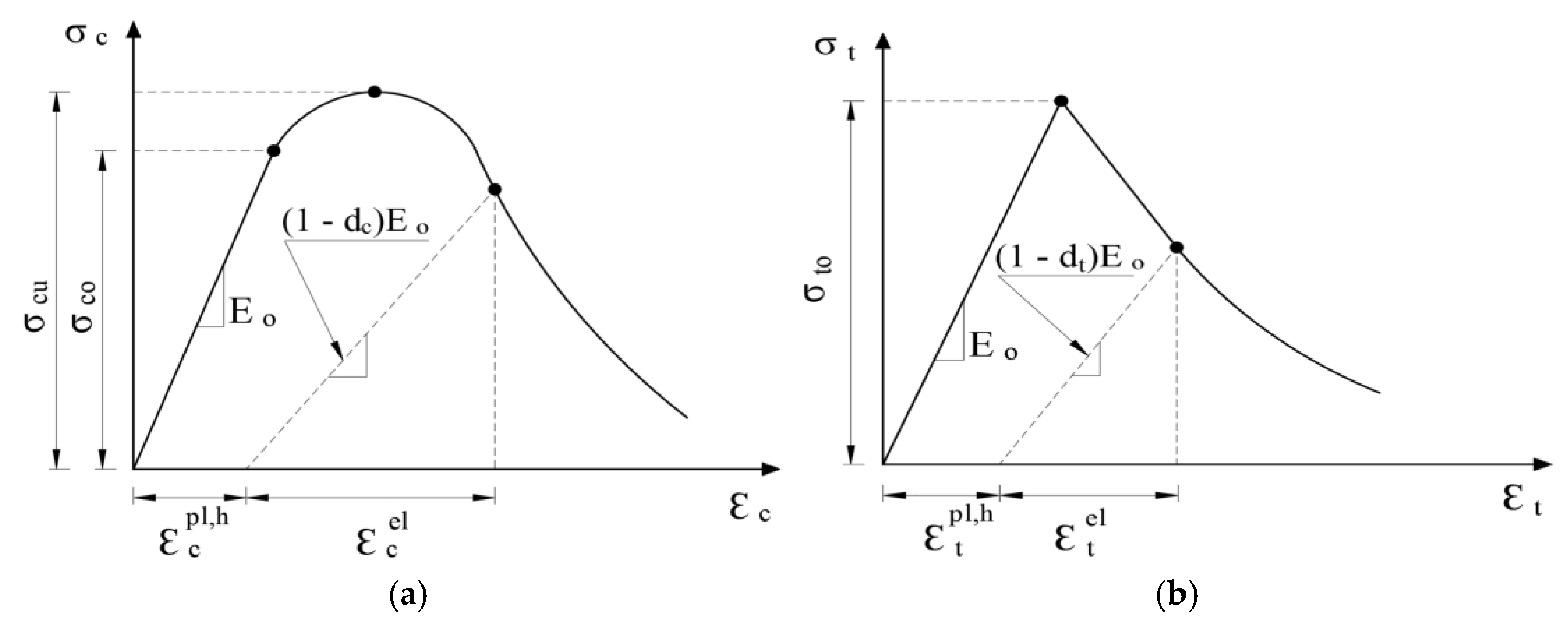
2.1.1. Concrete Behavior Model

ABAQUS was chosen for this study because it provides reliable and flexible tools for modeling the complex behavior of concrete, especially when it cracks or deforms under loads. Furthermore, ABAQUS [54] offers multiple approaches for modeling concrete behavior in finite element simulations [59,60]. The commonly used concrete models in ABAQUS include smeared cracking, brittle cracking, and the concrete damaged plasticity (CDP) model [61]. The smeared cracking model treats concrete as a uniform material without explicitly modeling cracks, while the brittle cracking model simulates discrete cracks in brittle materials. In this study, the CDP model was chosen because it captures both cracking and plastic deformation, making it more appropriate for modeling the nonlinear behavior of reinforced concrete structures. The CDP model represents concrete as a continuous material while capturing cracking behavior through evolving damage variables, which reduce the stiffness after cracking and influence post-cracking responses (Figure 1). Additionally, CDP incorporates plasticity components, allowing for inelastic deformation before failure [61]. This makes it particularly useful for modeling reinforced concrete (RC) structures, where both cracking and plastic deformation play significant roles. The choice between the CDP model and the smeared cracking model depends on their varying complexity and assumptions. The most suitable model is determined by the specific simulation objectives and the availability of experimental data [62].
Tension stiffening is a phenomenon in reinforced concrete structures where the concrete between cracks stiffens due to the tensile stress transfer from the reinforcing rebars. This effect enhances the structure’s load-carrying capacity. In ABAQUS, tension stiffening is incorporated through the CDP model, which accounts for the concrete stiffness degradation due to cracking while also capturing the stiffening effect of the reinforcement. The CDP model represents cracking through a scalar damage variable and includes a tension stiffening function to describe the increased stiffness resulting from the tensioned reinforcement. Properly defining key parameters, such as tensile strength and the tension stiffening function, is crucial for accurate simulations. Additionally, specifying the reinforcement layout and material properties is essential to accurately model the interaction between the concrete and reinforcement. Once these parameters are set, ABAQUS can simulate the RC structure’s behavior under the load, incorporating the tension stiffening effect. This significantly enhances the analysis accuracy, particularly for structures subjected to tensile forces.
This study adopted the Hsu and Hsu [63] model for the compressive stress–strain relationship and the CEB-FIP code [64] for tension stiffening and incorporated minor modifications based on sensitivity analyses from the authors’ previous study [58]. Table 1 provides a comprehensive summary of the CDP parameters, compressive stress–strain relationships, and tensile stress–crack opening relationships. The concrete tensile and compressive strength values used in the present study are 2.33 MPa and 50 MPa, respectively. The corresponding fracture energy values were then determined using the equations provided in Table 1.

2.1.2. Steel Reinforcement Characteristics

In ABAQUS, the steel reinforcement was modeled using a bi-linear stress–strain relationship, characterized by an elastic modulus of 210 GPa and a yield stress of 508 MPa [65]. After defining these material properties, a tie constraint was applied to attach the reinforcing rebars to concrete or other structural elements, ensuring a proper load transfer. This constraint specified both the attachment points and the bond stiffness between the rebars and surrounding materials. Based on validation results from [58], a full bonding interaction between the steel reinforcement and concrete was assumed by defining embedded regions. Additionally, stirrups were assigned to the same material properties as the main reinforcement, with adjustments made to account for their different diameters.

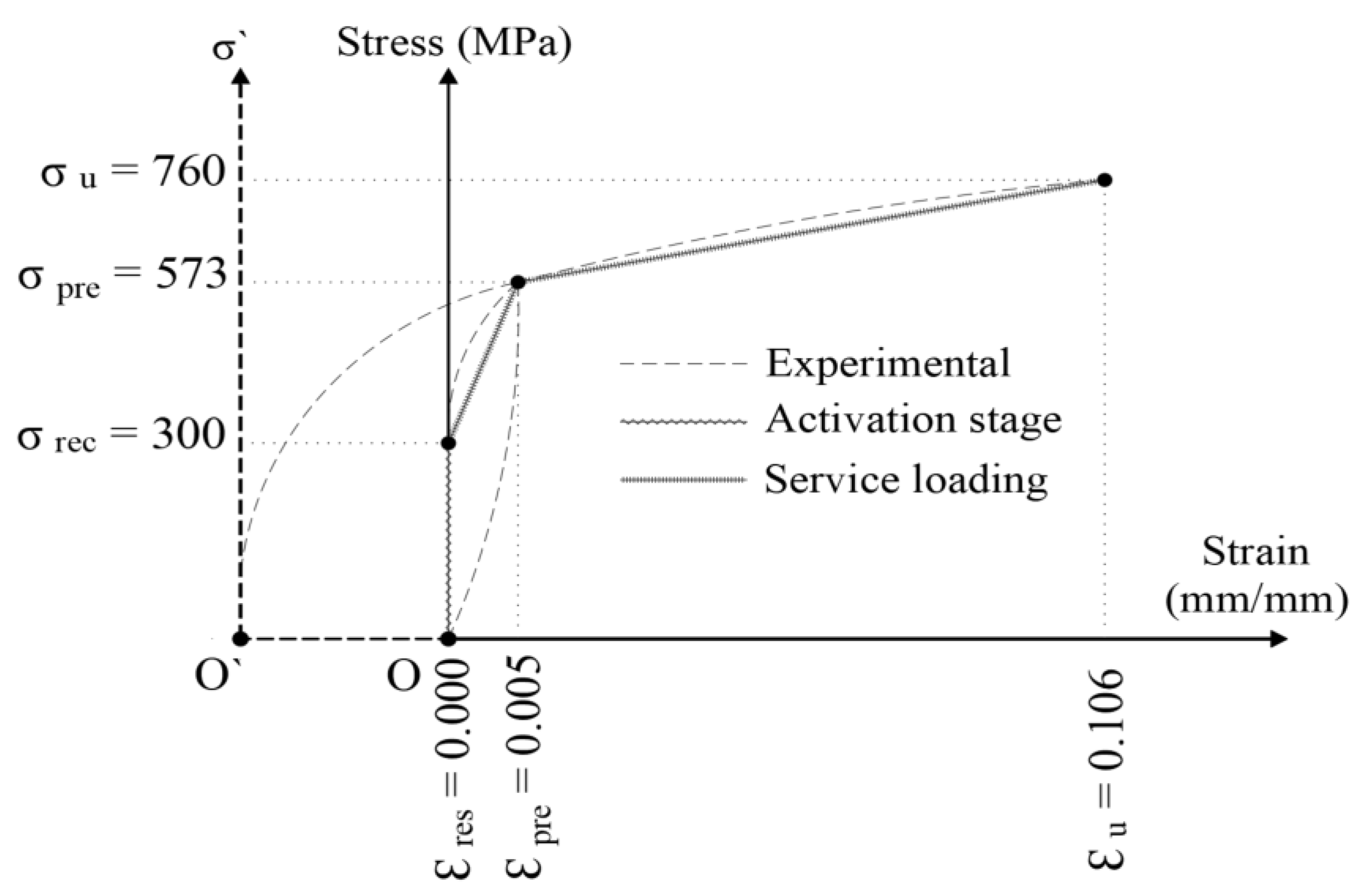
2.1.3. Fe-SMA Mechanical Properties

Recent studies, i.e., [66,67,68,69], have explored the potential of Fe-SMAs in civil engineering applications. Although their use remained in the early stages, advancements in alloy compositions and manufacturing had expanded their prospects, particularly for structural repair and pre-stressed tendon applications. This study adopted the material properties of Fe-SMA as defined by Shahverdi et al. [57], with a full bonding between the Fe-SMA rebars and concrete modeled in ABAQUS based on experimental findings. The chemical composition of the simulated Fe-SMA rebars followed a mass ratio of Fe-17Mn-5Si-10Cr-4Ni-1(V, C), with an elastic modulus of 133 GPa and a Poisson’s ratio of 0.30 [57]. Since ABAQUS lacked built-in Fe-SMA models, a two-step technique was used to simulate the pre-stressed Fe-SMA rebar behavior. First, the experimentally derived stress–strain curve from Shahverdi et al. [57] was defined in the material properties, similarly to conventional steel rebars. Second, a pre-defined field was activated to introduce the recovery stress, accounting for the pre-stressing effect. Figure 2 illustrates the adopted stress–strain relationship for the Fe-SMA. As shown in Figure 2, the stress–strain response of the Fe-SMA was modeled in three stages: the experimental curve (black dashed line), the activation stage (zigzag line), and the service loading stage (dotted line). During activation, the rebar is heated and then unloaded after being stretched to a pre-defined strain (εpre). This results in a recovery stress (σrec) and leaves a permanent residual strain (εres) in the material. In ABAQUS, this behavior is captured by horizontally shifting the curve by εpre and vertically by σrec, as illustrated by the zigzag line in Figure 2. Additional details regarding these key parameters and modeling approach are available in the authors’ previous study (Khalil et al. [58]).

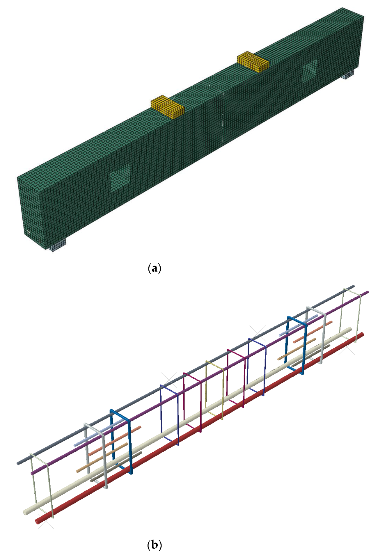
2.2. Finite Element Discretization and Solution Approach

2.2.1. Element Selection and Mesh Refinement

In ABAQUS, the C3D8R element was used to model concrete components, as shown in Figure 3a. This eight-node solid element employed reduced integration to enhance computational efficiency by minimizing the number of integration points. It featured three degrees of freedom (DOFs) per node (translations in the x, y, and z directions) and was well-suited for simulating simple 3D structures, such as the simply supported beam presented in this study.
For reinforcement modeling, this study used the T3D2 element, a three-node, linear displacement-based element designed for 3D simulations. Each node in this element had six degrees of freedom, including three translational and three rotational DOFs. As depicted in Figure 3b, the T3D2 element was used to define steel and Fe-SMA rebars, making it an ideal choice for analyzing reinforcement behavior in static and dynamic structural simulations. Additionally, it was widely employed in problems involving stress concentrations and adhesive joint modeling.
In ABAQUS, the mesh size played a crucial role in balancing the simulation accuracy and computational efficiency. It defined the size of individual elements in the finite element mesh, which represented the model’s geometry. Generally, a finer mesh (smaller elements) improved accuracy but increased the computational cost and processing time, whereas a coarser mesh (larger elements) reduced computational demands at the expense of precision. The optimal mesh size depended on the simulation’s specific requirements. A common approach was to begin with a coarse mesh and refine it progressively until the results converged to a satisfactory accuracy level. Based on a sensitivity analysis from the authors’ previous study [58], this research adopted a 20 mm element size, achieving a balance between accuracy and efficiency. Additionally, tie constraints in ABAQUS were used to enforce displacement compatibility between connected surfaces or edges, ensuring they move as a single unit. Once applied, any displacement of one tied surface was transferred to the other, maintaining rigid connectivity. This study employed surface-based tie constraints to link different elements, as illustrated in Figure 3.

2.2.2. Convergence Criteria and Solution Controls

In ABAQUS, convergence criteria ensure the accuracy and stability of the solution during the iterative process. These criteria determined when the solution had reached a sufficiently accurate state, allowing the iteration to stop. ABAQUS offers a variety of convergence control options, including the quasi-Newton method, the separated method, field equations, and constraint equations. However, adjustments were rarely necessary, as the default settings generally ensured a sufficient accuracy. In this study, the default convergence controls were utilized, and the solution efficiently converged without requiring modifications.

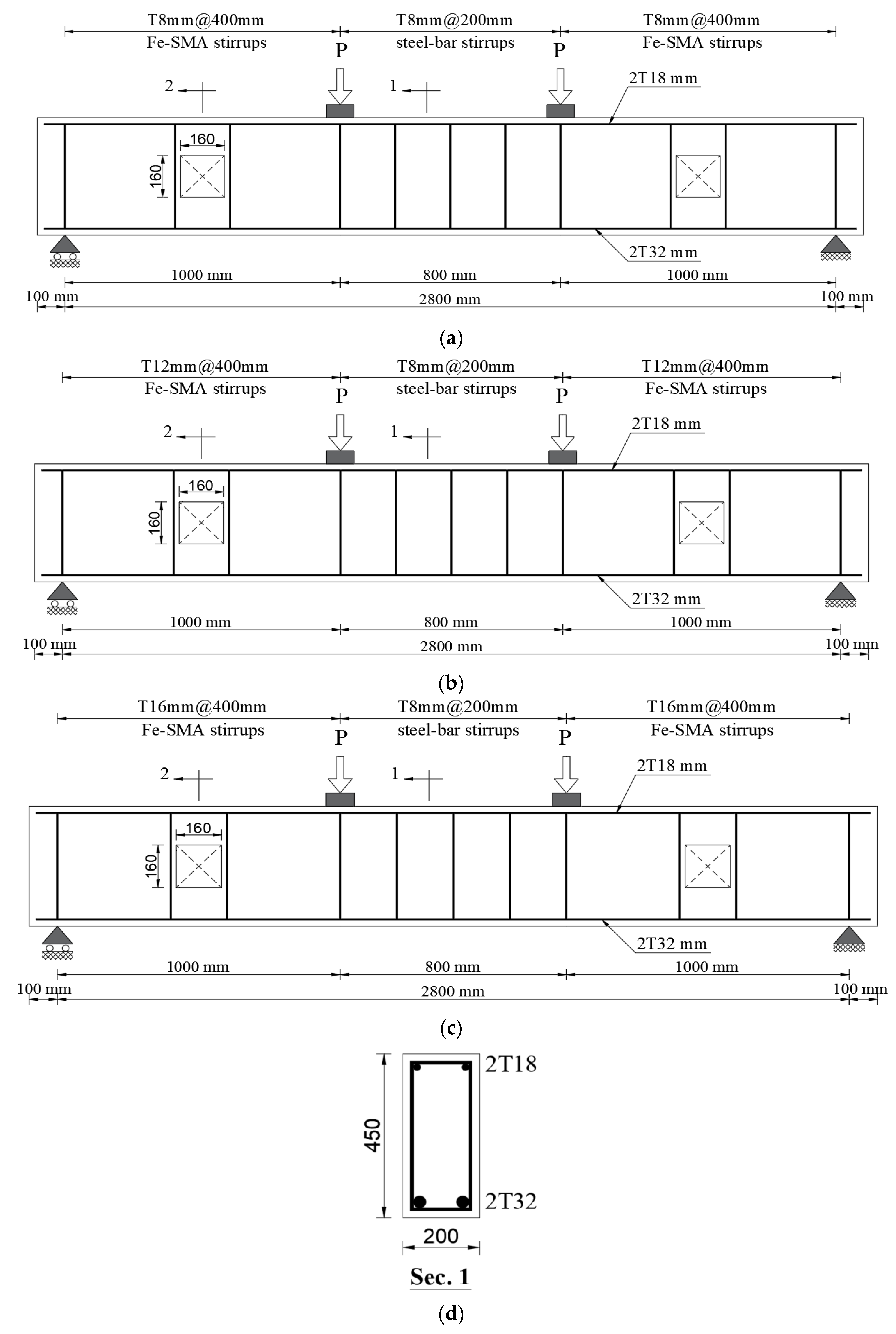
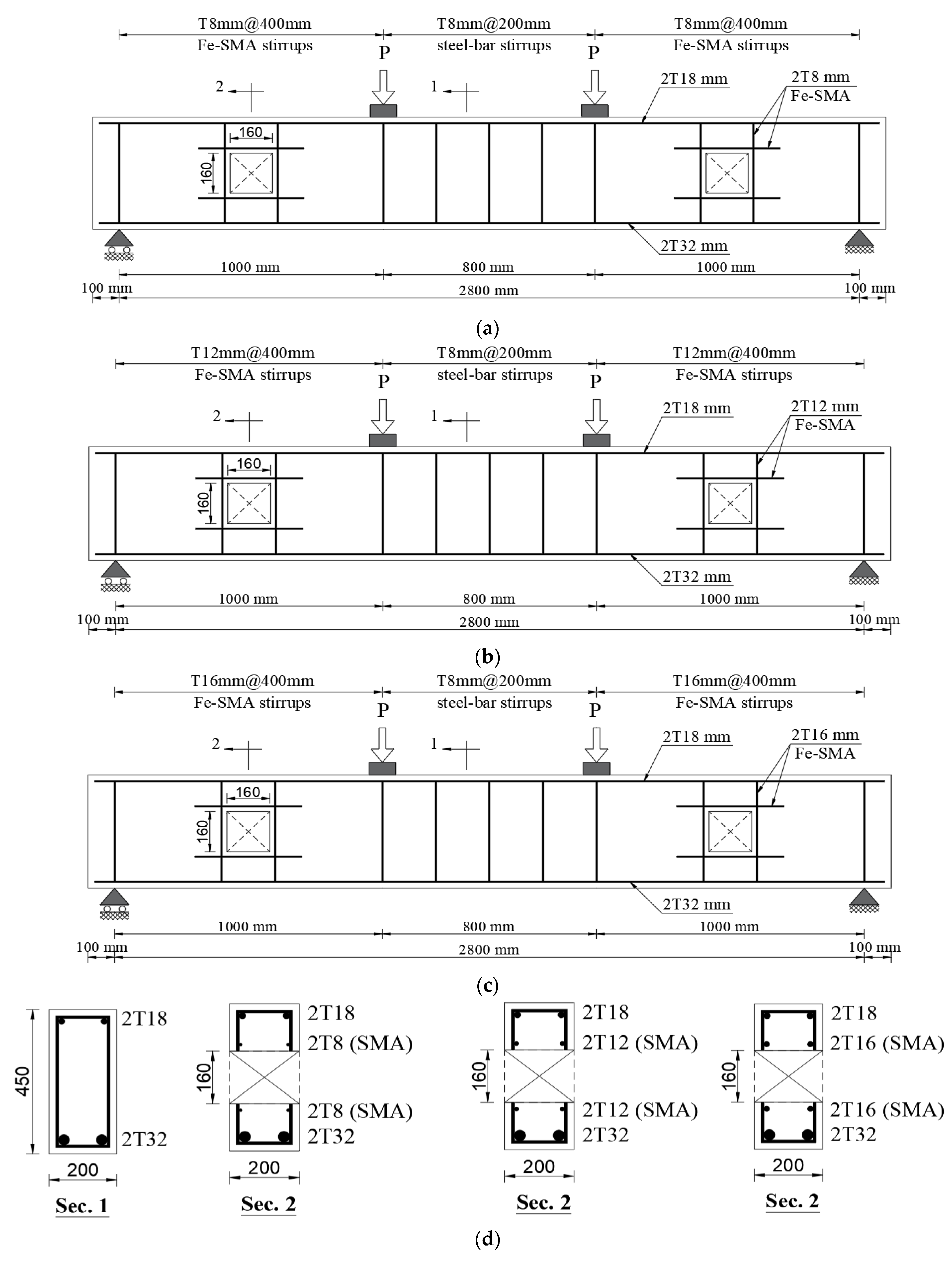
2.3. Specimen Geometry and Reinforcement Configurations

This study’s parametric investigation was divided into three groups, and each consisted of three specimens, along with two control beams (BC and BO), as summarized in the test matrix presented in Table 2. The typical RC beam cross-section measured 450 mm in depth, 200 mm in width, and 3000 mm in length. Each beam identity (ID) specified the spacing of the Fe-SMA stirrups, stirrup diameter, and presence of the horizontal reinforcement. For example, BO-T8-400 designated a RC beam with Fe-SMA stirrups of 8 mm diameter spaced at 400 mm, while BO-T12-400-H represented a RC beam with 12 mm Fe-SMA stirrups with a 400 mm spacing, including the horizontal reinforcement.
To standardize conditions for the comparison, a fixed square web opening of 160 mm × 160 mm was adopted across all specimens. Each RC beam was designed to fail in shear and tested under a four-point loading configuration with a 1000 mm shear span. While stirrups of an 8 mm diameter with a 200 mm spacing were consistently applied along the clear span, the shear regions were reinforced with varying configurations to assess their effect on the structural performance as part of this parametric investigation. This study specifically focused on the influence of the Fe-SMA stirrup spacing, diameter, and horizontal reinforcement placement. The control RC beams (BC and BO) served as benchmarks, with BC representing a solid RC beam and BO a RC beam with an unreinforced opening. Figure 4 presents the geometries of the control beams (BC and BO) and the specimen cross-sectional details.
To thoroughly assess the influence of key reinforcement parameters, this study classified the specimens into three distinct groups (Group I, Group II, and Group III), as previously mentioned, each targeting a specific variable. Group I investigates the effect of the Fe-SMA stirrup spacing, with three beams having 8 mm diameter stirrups at different spacings (100 mm, 200 mm, and 400 mm). Group II examined the impact of the Fe-SMA stirrup diameter, maintaining a 400 mm spacing while varying the stirrup diameter (8 mm, 12 mm, and 16 mm). Group III explored the influence of the horizontal reinforcement, using identical spacing (400 mm) and varying diameters (8 mm, 12 mm, and 16 mm) of both stirrups in the shear spans and the horizontal reinforcement. Figure 5, Figure 6 and Figure 7 depict the geometries of the RC beams in Group I, Group II, and Group III, respectively, along with their corresponding cross-sectional details.

3. Results and Discussion

3.1. The Validation of the Numerical Model

A finite element model (FEM) verification is essential to ensure that the numerical model accurately represents the behavior of the physical system it simulates. This process involves comparing FEM results with experimental data to confirm the model’s reliability. In this study, the verification is conducted by validating the FEM predictions against the experimental findings of Shahverdi et al. [57]. Their tests revealed that all RC beams exhibited flexural failure, characterized by steel reinforcement yielding, followed by concrete crushing under compression.

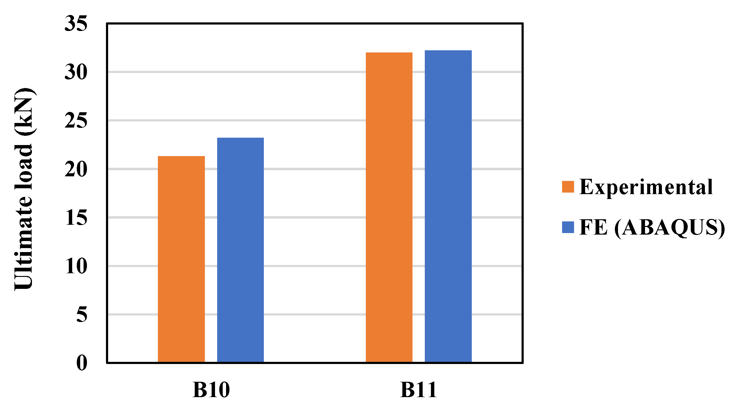
3.1.1. Comparison with Experimental Data

The FEM validation was previously addressed in the authors’ previous study [58], and repetitive details have been omitted here to maintain the focus on the shear parameters investigated in this work. Nevertheless, essential verification aspects, such as load-deflection behavior, cracking patterns, and failure modes, were reported in this study. The comparison involved two tested RC beams: Beam 10 (B10), reinforced with two ribbed Fe-SMA bars, and Beam 11 (B11), which incorporates four ribbed Fe-SMA bars. Figure 8 compared the measured (experimental) and simulated (FEM) ultimate load capacities. The results indicated a good agreement between the numerical and experimental data, with minor discrepancies attributed to numerical approximations and material modeling assumptions. Several factors influenced the FEM accuracy, including the mesh density, material behavior modeling, and boundary condition definitions. While a finer mesh improved precision, material properties like concrete cracking models and tension stiffening effects impacted stiffness predictions. Despite these sensitivities, the overall verification results confirmed the FEM’s reliability in capturing structural behavior for the RC beams.

3.1.2. Assessment of Load-Deflection Behavior and Cracking Patterns

Figure 9a,b compared load-deflection curves from FEM simulations and Shahverdi et al. [57]’s experimental results. Beams 10 and 11, strengthened with Fe-SMA rebars embedded in a shotcrete layer, demonstrate a strong agreement between numerical and experimental curves. However, some differences are noticeable in the early loading stages. These variations may result from limitations of the numerical model in fully capturing real experimental conditions. For example, the initial thermal microcracks or imperfect bonding between materials are difficult to simulate accurately. Additionally, the simulation assumes a fully bonded contact surface, which may not perfectly match the real interface behavior observed in experimental tests. It is also important to note that the simulations for Beams 10 and 11 were intentionally stopped at deflection values close to the maximum deflections observed during testing. This was done to ensure a direct and fair comparison with the experimental data. Beams 10 and 11 were chosen as representative samples due to their stable and consistent performance in the experimental tests. Simulating additional beams with similar configurations was deemed unnecessary, as these two effectively validated the modeling approach while optimizing the computational effort. The close alignment between both datasets confirms the accuracy and reliability of the FEM in this study, reinforcing its suitability for simulating the structural behavior of RC beams.

3.2. Parametric Investigation

In RC beams, shear forces were transferred between the upper and lower sections through both the concrete and shear reinforcement. When the applied shear force increased, it induced diagonal tensile stresses along the shear plane. Shear cracks started to develop once the stresses exceeded the concrete’s tensile capacity. Previous studies have extensively examined shear cracking behavior in RC beams [70,71,72]. The presence of web openings within the shear span significantly influenced the stress distribution and shear flow [73] and potentially altered the shear crack initiation and propagation. This study thoroughly investigated these effects by classifying the RC beams into three parametric groups based on the Fe-SMA stirrup spacing, Fe-SMA stirrup diameter, and horizontal reinforcement.

3.2.1. Influence of Stirrup Spacing

Introducing openings within the shear span significantly influences the load-deflection behavior of RC beams by reducing the shear capacity and increasing the risk of structural failure. Understanding these effects is essential for developing appropriate design strategies that ensure the safe use of RC beams with such discontinuities in practical applications. As shown in Figure 10, the solid beam (BS) achieves the highest ultimate load capacity of 540 kN, highlighting the vital role of the continuity of concrete in resisting shear forces. In contrast, the unstrengthened beam with two identical 160 mm × 160 mm openings (BO) exhibits a substantial reduction in load capacity, reaching only 335 kN, a 38% decrease compared to the BS. Openings in RC beams lead to a reduction in shear strength due to the geometrical discontinuity and sectional loss. This reduction can be substantial, ranging from 2% to 53% depending on the size and location of the openings [74,75,76]. The presence of openings causes a stress concentration around the openings, leading to premature cracking and stiffness degradation. The depth and length of the openings are negatively correlated with the ultimate shear strength. The location of the openings along the shear span also significantly impacts the beam’s capacity and behavior [74,75,76]. FEM simulations, validated against experimental results, can predict the ultimate strength, load–deflection relationship, and crack propagation in beams with openings.
Strengthening the BO beam with T8 Fe-SMA stirrups at different spacings (100 mm, 200 mm, and 400 mm) leads to significant improvements in the load capacity, reaching 446 kN, 439 kN, and 427 kN, respectively. These represent a 33%, 31%, and 27% increase compared to the BO beam. Among these, BO-T8-100 achieves the highest performance, restoring 83% of the capacity of the solid beam, while BO-T8-200 and BO-T8-400 restore 81% and 79%, respectively. This trend is supported by previous studies, which indicates that reducing the stirrup spacing enhances the confinement around shear cracks, facilitates internal load redistribution, and delays failure [74,75,76]. While this structural improvement is well-documented, it comes with a trade-off that the close spacing of stirrups can complicate the construction process, making it difficult to place and secure the stirrups properly, which can lead to increased labor and time costs [77]. Thus, despite the clear structural improvement, practical implementation challenges must be carefully considered. Although the strengthened RC beams do not fully replicate the capacity of the solid beam, they provide a significant structural enhancement and help mitigate the negative effects introduced by shear span openings. Minor variations in the post-peak behavior are attributed to numerical approximations affecting the stiffness degradation.
Although this trend is consistent with findings reported in previous studies, its influence may not be distinctly visible in the numerically generated crack patterns, as will be further elaborated in Section 3.2.4. This may be due to typical FEM limitations, such as the mesh density and crack visualization techniques. Therefore, an experimental validation is advised to reliably confirm the numerical observations.

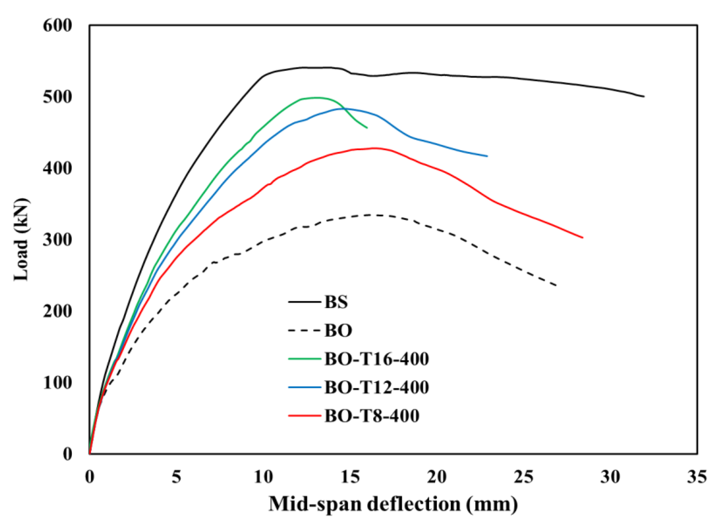
3.2.2. Impact of Fe-SMA Stirrup Diameter

Strengthening the BO beam using Fe-SMA stirrups of different diameters (8 mm, 12 mm, and 16 mm) results in a notable improvement in the load-deflection performance. As illustrated in Figure 11, beams BO-T8-400, BO-T12-400, and BO-T16-400 achieve ultimate load capacities of 427 kN, 482 kN, and 500 kN, respectively, representing 27%, 44%, and 49% increases compared to the unstrengthened BO beam (335 kN). Among these, BO-T16-400 demonstrates the highest structural performance, restoring approximately 93% of the capacity of the BS (540 kN), while BO-T12-400 and BO-T8-400 restore 89% and 79%, respectively. This trend highlights the positive influence of increasing the stirrup diameter on the shear resistance and load capacity recovery. This outcome aligns with previous studies, which suggest that increasing the diameter of stirrups generally enhances the shear capacity of RC beams. This is because larger diameter stirrups can provide a greater confinement and resistance to shear forces [78]. Although the Fe-SMA reinforcement does not fully replicate the behavior of the solid beam, it provides a substantial improvement in both stiffness and strength. Larger rebar diameters enhance the load capacity and reduce congestion but require careful design, skilled labor, and proper construction practices to manage associated challenges [79,80]. Nevertheless, these findings support the effectiveness of the Fe-SMA stirrup diameter enhancement as a practical strategy for strengthening RC beams affected by web openings. Given that this trend is reasonable and supported by several studies in the aforementioned literature, it remains valid; however, its effect may not be clearly reflected in the crack patterns produced numerically, as will be further discussed in Section 3.2.4. Given the limitations of the FEM, such as the mesh resolution and damage visualization, experimental validation is recommended to confirm the observed trends.

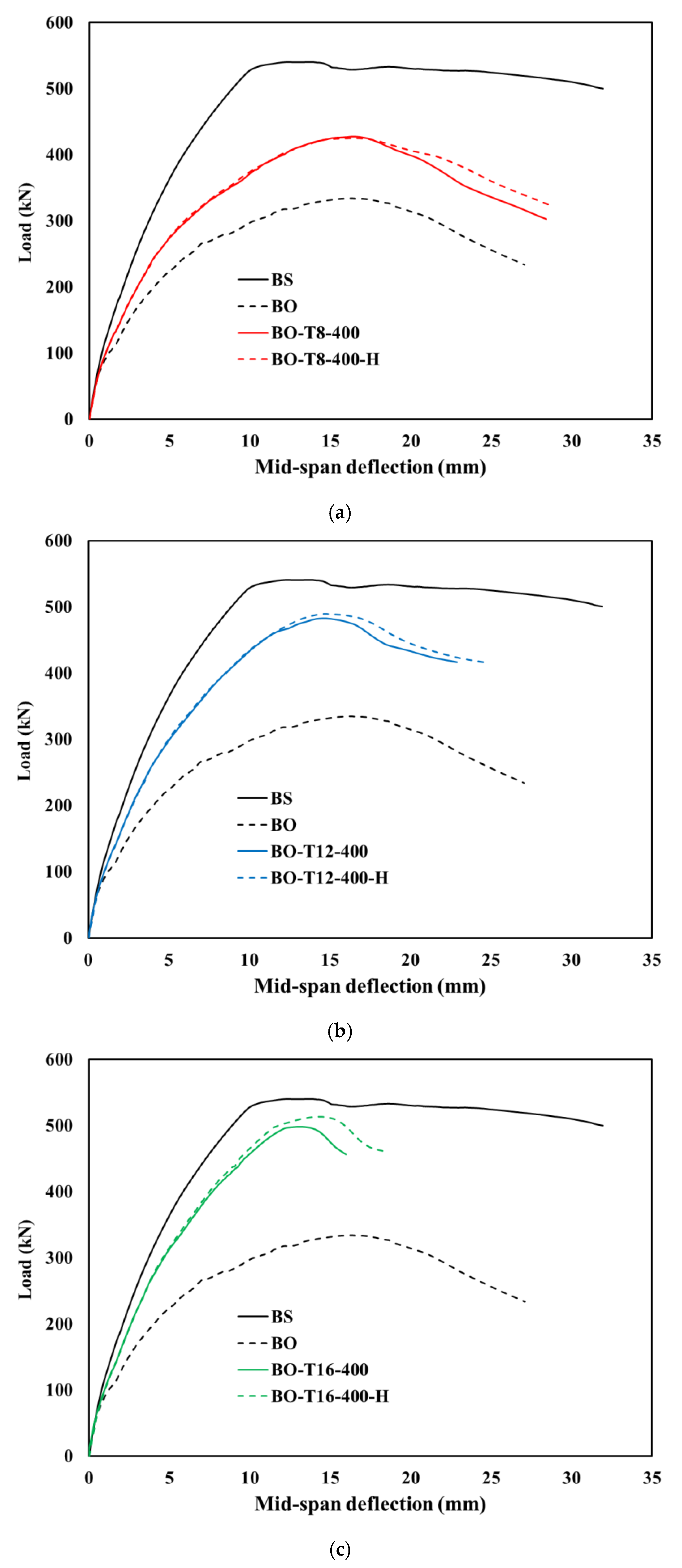
3.2.3. Effect of Horizontal Reinforcement

Strengthening RC beams with web openings using horizontal reinforcements in combination with Fe-SMA stirrups significantly enhances their load-deflection performance. Figure 12a–c present the results of specimens incorporating the effect of both the horizontal reinforcement and Fe-SMA stirrups with varying diameters, 8 mm, 12 mm, and 16 mm, while maintaining a constant spacing of 400 mm, as previously identified as optimal in Section 3.2.1. When strengthened using this combined approach, the BO-T8-400-H, BO-T12-400-H, and BO-T16-400-H beams achieved ultimate load capacities of 425 kN, 490 kN, and 513 kN, respectively. These results correspond to 27%, 46%, and 53% increases in the load capacity relative to the unstrengthened BO beam. In terms of performance restoration, BO-T16-400-H recovered approximately 95% of the solid beam’s capacity, while BO-T12-400-H and BO-T8-400-H restored 91% and 79%, respectively.
This trend confirms the progressive structural benefit of increasing the stirrup diameter when used alongside a horizontal reinforcement. As previously observed in Section 3.2.2, the 16 mm Fe-SMA stirrup consistently achieved the best performance among all tested diameters. Strengthening RC beams with web openings using horizontal reinforcements in combination with larger stirrup diameters generally enhances the shear capacity of the beams. This approach effectively addresses the challenges posed by web openings, ensuring an improved structural performance. The horizontal reinforcement combined with stirrups helps resist diagonal tension, delays cracking, reduces the crack width, and improves the rigidity and shear strength [81,82]. Furthermore, the combined use of horizontal reinforcement with larger stirrups together helps delay failure mechanisms and improve the overall load-carrying behavior of RC beams with openings [81,83]. Although strengthened beams did not fully replicate the solid RC beam’s behavior, BO-T16-400-H nearly restored the original performance, demonstrating its effectiveness as an optimized shear-strengthening solution.

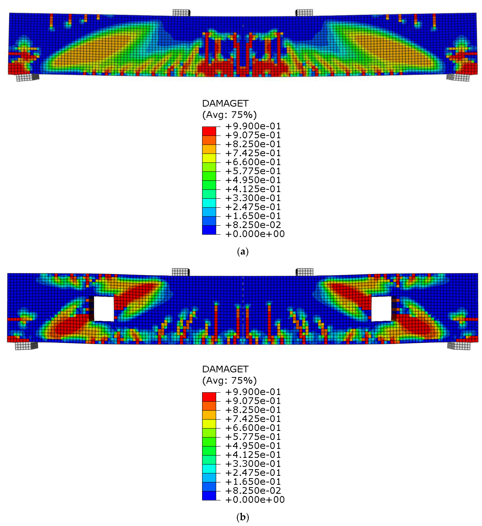
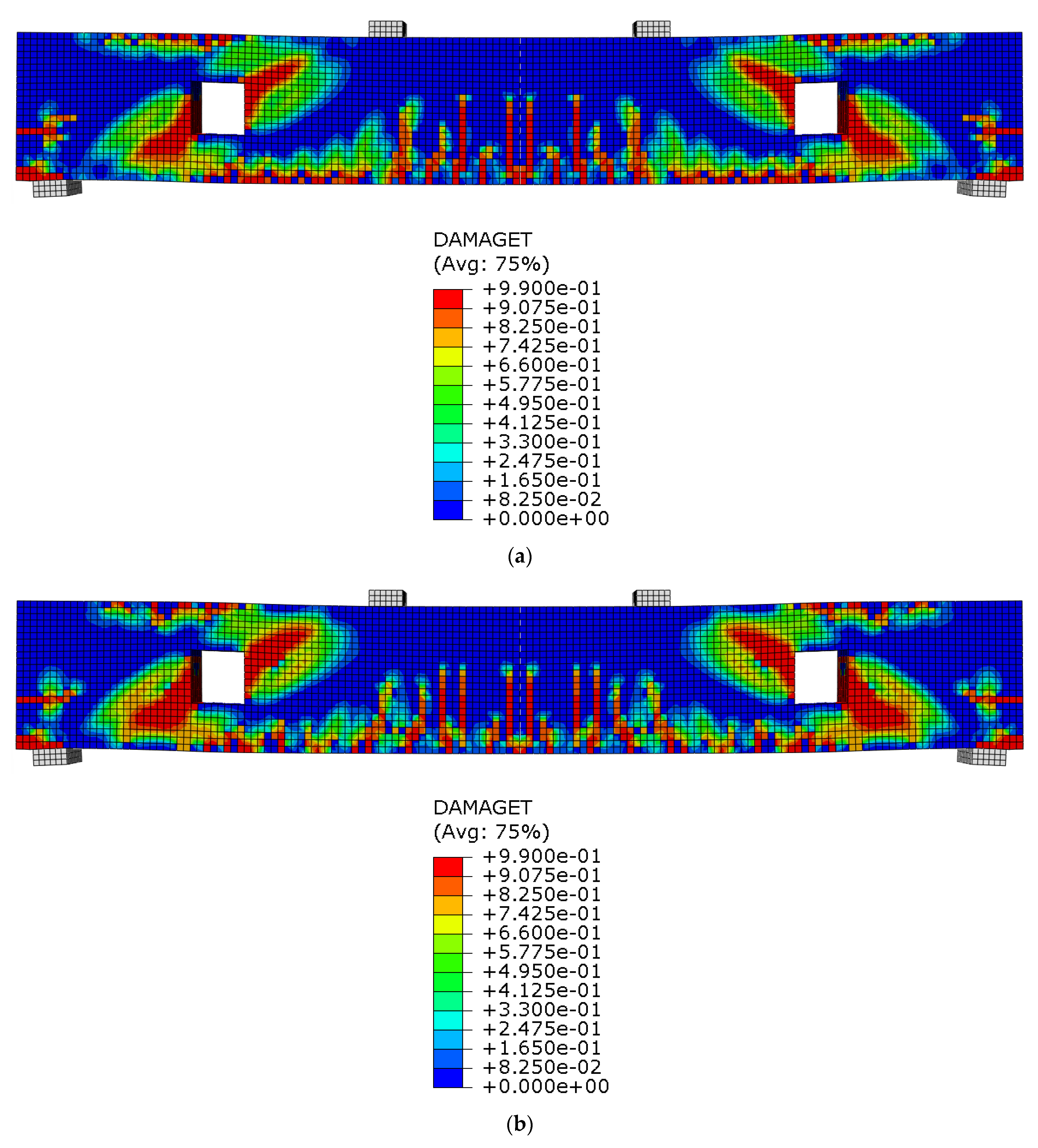
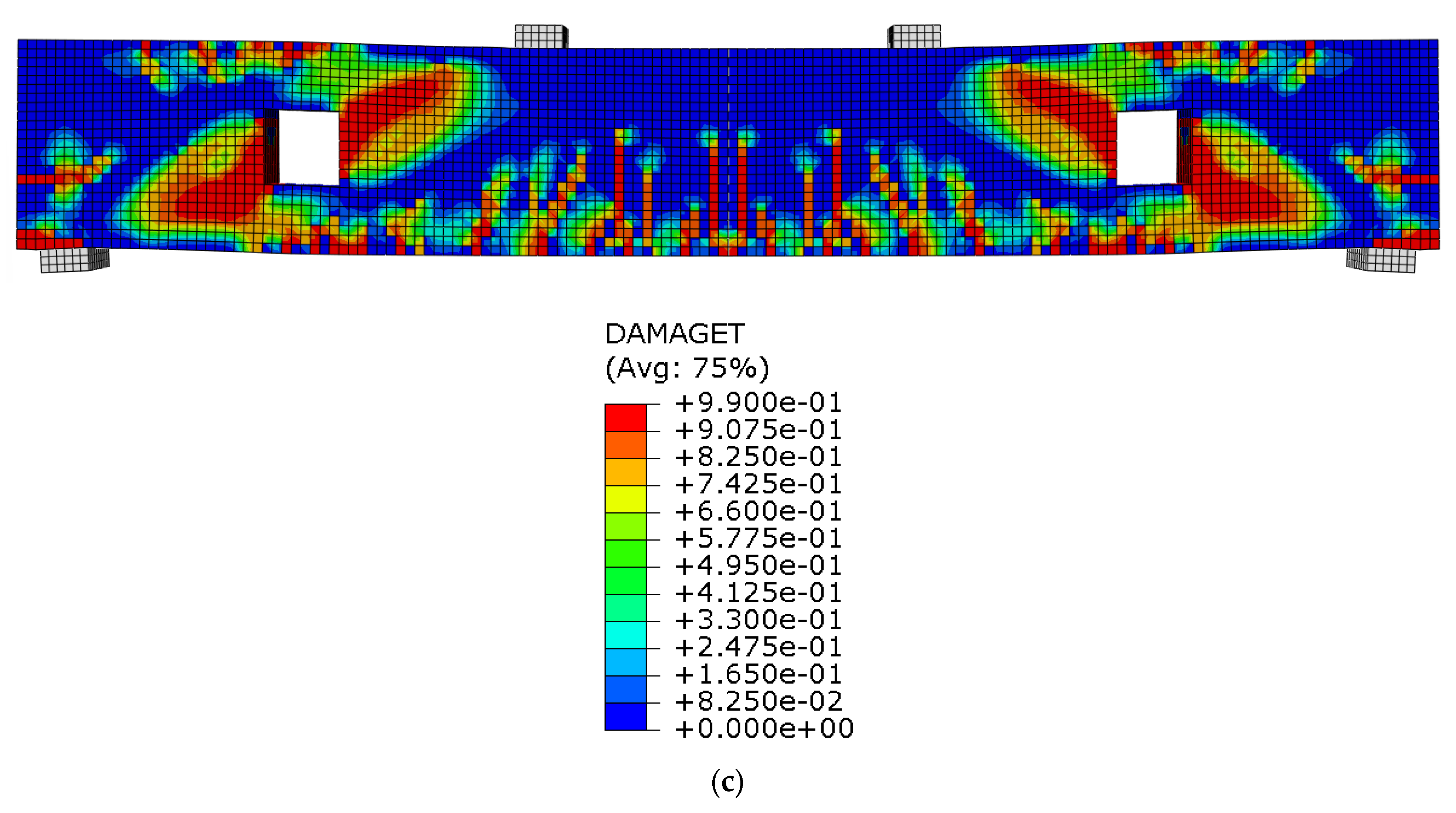
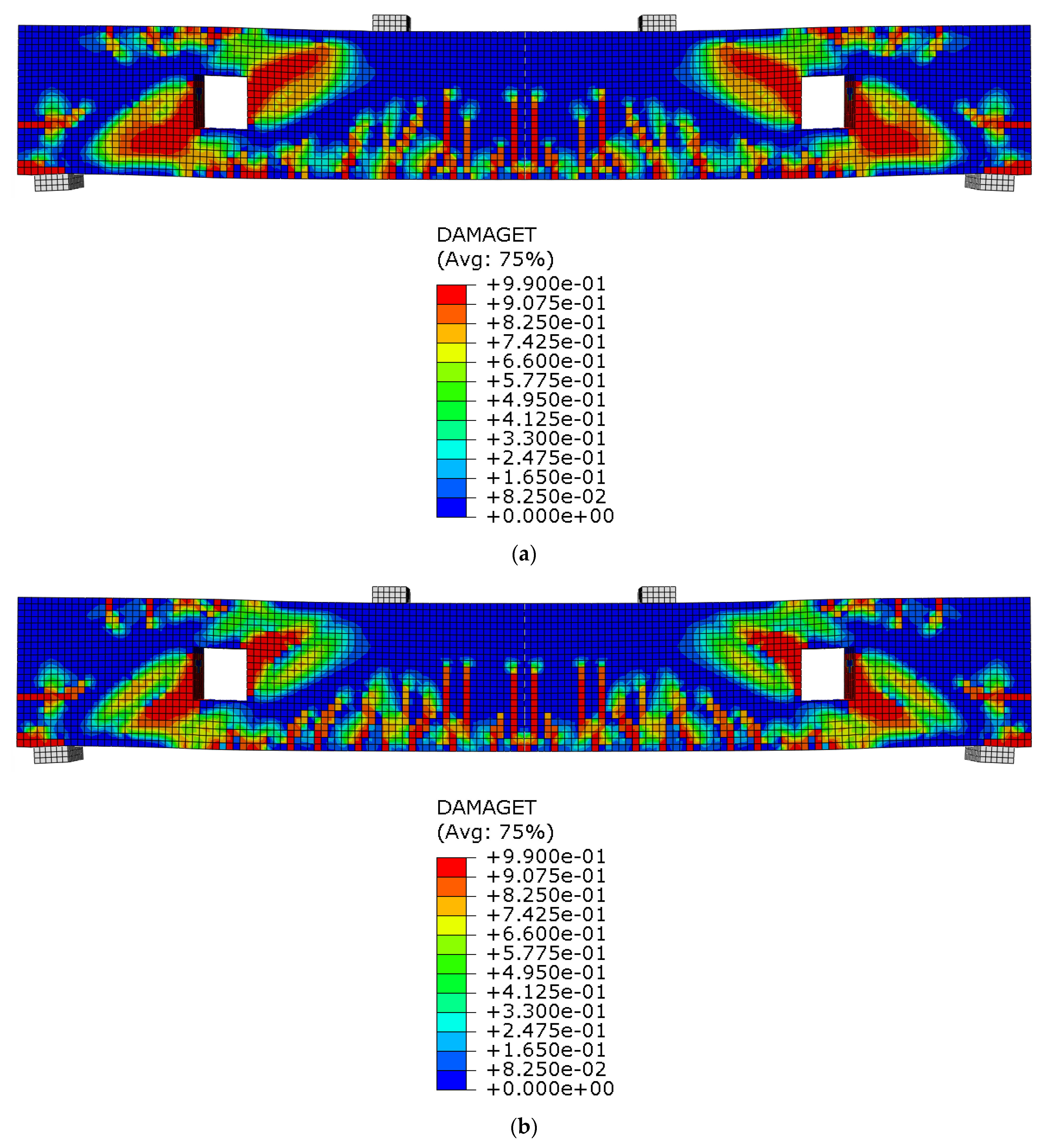
3.2.4. Crack Pattern

Figure 13 presents the crack patterns observed in RC beams at ultimate loads, comparing the BS with the BO. In the solid beam (Figure 13a), discrete diagonal shear cracks are observed, extending from the support regions toward the loading points. This classic cracking pattern indicates the formation of a continuous diagonal compression strut, which is essential for transferring shear forces effectively across the span. In contrast, the beam with openings (Figure 13b) exhibits a markedly different behavior. Web openings disrupt the internal force flow along the shear path, leading to concentrated cracking and a poorly developed diagonal strut. This disruption leads to a more irregular and dispersed crack distribution, which significantly reduces the beam’s shear capacity. This reduction is influenced by several factors, particularly the arrangement and detailing of the shear reinforcement, making both its quantity and configuration critical to controlling the crack development. An inadequate shear reinforcement often leads to a single dominant shear crack, significantly reducing the beam’s shear capacity [84]. Thus, this study focuses on investigating key shear configurations that affect the crack behavior and failure mechanisms in RC beams. The observed results align well with existing numerical and experimental studies, which have shown that web openings weaken the diagonal strut formation, increase stress concentrations, and alter typical failure patterns. Additionally, previous studies demonstrated that strengthening methods like FRP, Fe-SMA, and enhanced shear reinforcement configurations can mitigate the force redistribution from web openings and partially restore the RC beam performance [40].
Figure 14 illustrates the influence of the Fe-SMA bar spacing on the crack behavior of RC beams with web openings, highlighting how the reinforcement configuration affects the stress distribution and crack development. In all three cases (spacings of 100 mm, 200 mm, and 400 mm in Figure 14a, Figure 14b, and Figure 14c, respectively), stress concentrations occur around the corners of the openings, initiating diagonal and vertical cracks that extend outward into the surrounding concrete. Although the overall crack patterns appear visually similar, subtle differences can still be observed in the intensity and spread of the cracking. For the beam with the closest Fe-SMA spacing (BO-T8-100), cracks appear slightly more localized near the opening, which may suggest a marginally better confinement and crack control due to the higher confinement and reinforcement (Fe-SMA) density. In contrast, BO-T8-200 and BO-T8-400 show a broader crack dispersion, especially in the tension zone and lower web region, though the variation is not highly pronounced. These modest differences indicate that while reduced spacing may offer some improvement in crack control, the effect is not strongly evident in the simulated patterns. This may be attributed to limitations in the finite element modeling sensitivity, the mesh resolution, or the damage visualization scale used in the output, which can mask subtle differences in crack propagation. Therefore, it is highly recommended to conduct an experimental validation to confirm and support the trends observed in this numerical study. These trends are consistent with previous studies, which found that reducing the Fe-SMA stirrup spacing significantly improves the shear strength and crack control. Additionally, activating Fe-SMA stirrups has been shown to delay the crack initiation and enhance the initial stiffness through an active confining pressure [56,85].
Figure 15 illustrates the crack patterns in RC beams with a constant Fe-SMA bar spacing (400 mm) but varying bar diameters: 8 mm (BO-T8-400), 12 mm (BO-T12-400), and 16 mm (BO-T16-400). In all three specimens, cracks initiate around the corners of the web openings due to stress concentrations and propagate vertically and diagonally toward the tension zone. While the general crack patterns across the three configurations appear visually similar, subtle differences in the crack density and localization can still be observed. For the BO-T8-400 beam (Figure 15a), the crack pattern is slightly more pronounced, with a higher concentration of vertical cracks along the bottom face, which may reflect the limited restraining capacity of the smaller-diameter bars. As the bar diameter increases to 12 mm (Figure 15b), the spread of cracks becomes somewhat more confined, suggesting an improved confinement and tensile stress resistance. This trend continues with the BO-T16-400 beam (Figure 15c), where cracks appear more scattered and less intense, though not drastically different from the previous cases. These subtle variations may be less evident due to limitations in the simulation’s mesh resolution, visualization thresholds, or damage indicators used. Therefore, experimental validation is highly recommended to validate these numerical observations. To the best of the authors’ knowledge, the current literature does not provide direct evidence on the specific effect of increasing the Fe-SMA stirrup diameter. However, findings from studies on conventional steel stirrups and FRP stirrups suggest that increasing stirrups’ diameter enhances the shear strength, ductility, and crack control [86,87]. By extension, it is reasonable to infer that similar improvements can be expected for Fe-SMA stirrups in terms of their load-bearing capacity, crack control, and overall structural performance.
Figure 16 visually supports the findings discussed in Section 3.2.3 regarding the effect of the horizontal reinforcement on the crack behavior and structural performance in RC beams with web openings. The three specimens, BO-T8-400-H, BO-T12-400-H, and BO-T16-400-H, demonstrate how increasing the diameter of the horizontally placed Fe-SMA enhances the crack control and mitigates damage under the load. In the BO-T8-400-H beam (Figure 16a), although a horizontal reinforcement is present, the smaller rebar diameter offers limited confinement, resulting in a relatively widespread crack pattern and less efficient stress redistribution. In contrast, the BO-T12-400-H specimen (Figure 16b) exhibits more crack control, indicating an improved stiffness and resistance due to the increased reinforcement diameter. This trend is most pronounced in the BO-T16-400-H beam (Figure 16c), where the crack pattern is notably confined and well-distributed, with minimal propagation toward the span center. This outcome aligns with the beam’s superior load-carrying performance reported earlier in Section 3.2.3. Previous studies support that the horizontal reinforcement restrains inclined crack growth, delays diagonal cracking, and helps maintain structural integrity in beams with web openings [88,89]. Moreover, the inclusion of the horizontal reinforcement helps reduce the width of diagonal cracks, contributing to better crack control and an enhanced long-term durability.

4. Conclusions

This study explored the structural response of RC beams with shear span openings, focusing on the application of Fe-SMA reinforcements. As the first-known investigation to assess Fe-SMA stirrups in beams with web openings, this analysis addressed shear-related variables, including the stirrup spacing, diameter, and horizontal reinforcement. The numerical findings demonstrate that introducing openings significantly compromises the beam performance, notably reducing the ultimate load capacity and accelerating crack development. However, strategically detailing Fe-SMA reinforcements offers an effective solution to mitigate these adverse effects. Key outcomes include the following:
  • Web openings reduced the ultimate load capacity of RC beams by up to 38% compared to solid beams.
  • Reducing the Fe-SMA stirrup spacing from 400 mm to 200 mm and 100 mm at a fixed 8 mm stirrup diameter partially restored the load capacity by 81% and 83%, respectively.
  • Increasing the stirrup diameter from 8 mm to 12 mm and 16 mm at a fixed 400 mm spacing partially recovered 89% and 93%, respectively, of the solid beam’s capacity.
  • Strengthening 160 × 160 mm2 openings with a horizontal Fe-SMA reinforcement, combined with larger stirrup diameters (increased from 8 mm to 16 mm), nearly restored the beam’s load-carrying capacity, achieving up to 95% of the solid beam’s original strength.
  • Web openings disrupt the internal force flow and shear paths, resulting in a scattered crack pattern and a significantly reduced shear capacity.
  • Reducing the Fe-SMA stirrup spacing improved crack control by confining cracks near the openings, while a wider spacing led to an increased crack density and propagation, weakening the compression strut mechanism.
  • Increasing the stirrup diameter improved the mechanical interlock and confinement, leading to a reduced crack density and propagation, even when the spacing remained constant.
  • Horizontal reinforcement played a key role in controlling the crack propagation, delaying strength degradation, and improving the structural integrity.
  • Optimizing the configuration and placement of the shear reinforcement is essential for ensuring a safe and durable performance in RC beams with web openings.
These insights offer valuable guidance for engineers and designers working with RC elements containing web openings. Nevertheless, further experimental validation is recommended to confirm and expand upon the findings of this numerical investigation.

Author Contributions

Conceptualization, M.E. and A.K.; methodology, M.E. and A.K.; software, M.E. and A.K.; validation, M.E. and A.K.; formal analysis, M.E. and A.K.; investigation, M.E. and A.K.; resources, M.E. and A.K.; data curation, M.E. and A.K.; writing—original draft preparation, M.E. and A.K.; writing—review and editing, M.E., A.K., R.H. and M.A.; visualization, M.E. and A.K.; supervision, R.H. and M.A.; project administration, R.H. and M.A.; funding acquisition, R.H. and M.A. All authors have read and agreed to the published version of the manuscript.

Funding

This research received no external funding.

Data Availability Statement

The original contributions presented in this study are included in the article. Further inquiries can be directed to the corresponding author.

Acknowledgments

The authors greatly appreciate the financial support they received. This paper represents the opinions of the authors and does not mean to represent the position or opinions of the AUS.

Conflicts of Interest

The authors declare no conflicts of interest.

References

  1. Golham, M.A.; Al-Ahmed, A.H.A. Behavior of GFRP reinforced concrete slabs with openings strengthened by CFRP strips. Results Eng. 2023, 18, 101033. [Google Scholar] [CrossRef]
  2. Hawileh, R.A.; El-Maaddawy, T.A.; Naser, M.Z. Nonlinear finite element modeling of concrete deep beams with openings strengthened with externally-bonded composites. Mater. Des. 2012, 42, 378–387. [Google Scholar] [CrossRef]
  3. Irmawan, M.; Piscesa, B. Performance of a Steel Fiber Reinforced Concrete Deep Beam with an Opening: A Non-linear Finite Element Analysis. In International Civil Engineering and Architecture Conference; Springer: Berlin/Heidelberg, Germany, 2024; pp. 359–368. [Google Scholar]
  4. Zeytinci, B.M.; Şahin, M.; Güler, M.A.; Tsavdaridis, K.D. A practical design formulation for perforated beams with openings strengthened with ring type stiffeners subject to Vierendeel actions. J. Build. Eng. 2021, 43, 102915. [Google Scholar] [CrossRef]
  5. Lawson, R.M.; Basta, A. Deflection of C section beams with circular web openings. Thin-Walled Struct. 2019, 134, 277–290. [Google Scholar] [CrossRef]
  6. Mohammed, M.Y.; Ali, A.Y.; Kadhim, M.M.A.; Jawdhari, A. RC deep beams with vertical openings: Behavior and proposed mitigation techniques. Pract. Period. Struct. Des. Constr. 2024, 29, 04023060. [Google Scholar] [CrossRef]
  7. Zuaiter, M.; El-Hassan, H.; El-Maaddawy, T. Shear behavior of glass fiber-reinforced slag-fly ash blended geopolymer concrete beams. Constr. Build. Mater. 2025, 466, 1. [Google Scholar] [CrossRef]
  8. Bolina, F.L.; Fisch, G.; Silva, V.P.E. RC beams with rectangular openings in case of fire. Rev. IBRACON De Estrut. E Mater. 2023, 16, e16206. [Google Scholar] [CrossRef]
  9. Attom, M.; El-Kadri, O.; Khalil, A. Optimization of Geothermal Energy Piles Design Parameters to Enhance Thermal Efficiency. In Proceedings of the 2024 5th International Conference on Clean and Green Energy Engineering (CGEE), Izmir, Turkey, 24–26 August 2024; IEEE: New York, NY, USA, 2024; pp. 83–87. [Google Scholar]
  10. Khalil, A.; Attom, M.; Khan, Z.; Astillo, P.V.; El-Kadri, O.M. Recent Advancements in Geothermal Energy Piles Performance and Design. Energies 2024, 17, 3386. [Google Scholar] [CrossRef]
  11. Farouk, M.A.; Moubarak, A.M.R.; Ibrahim, A.; Elwardany, H. New alternative techniques for strengthening deep beams with circular and rectangular openings. Case Stud. Constr. Mater. 2023, 19, e02288. [Google Scholar] [CrossRef]
  12. Galustanian, N.; El-Sisi, A.; Amer, A.; Elshamy, E.; Hassan, H. Review of the Structural Performance of Beams and Beam–Column Joints with Openings. CivilEng 2023, 4, 1233–1242. [Google Scholar] [CrossRef]
  13. Jagan, P.; Visuvasam, J.A. Assessment of dynamic soil-structure interaction effects on floating column structures with reinforced geotechnical isolation and shear wall system. Mech. Adv. Mater. Struct. 2025, 1–17. [Google Scholar] [CrossRef]
  14. Najar, I.A.; Ahmadi, R.; Amuda, A.G.; Mourad, R.; Bendary, N.E.; Ismail, I.; Bakar, N.A.; Tang, S. Advancing soil-structure interaction (SSI): A comprehensive review of current practices, challenges, and future directions. J. Infrastruct. Preserv. Resil. 2025, 6, 5. [Google Scholar] [CrossRef]
  15. Khalil, A.; Khan, Z.; Attom, M.; Fattah, K.; Ali, T.; Mortula, M. Continuous Evaluation of Shear Wave Velocity from Bender Elements during Monotonic Triaxial Loading. Materials 2023, 16, 766. [Google Scholar] [CrossRef]
  16. Khalil, A.; Khan, Z.H.; Attom, M.; El Emam, M.; Fattah, K. Dynamic properties of calcareous sands from urban areas of Abu Dhabi. Appl. Sci. 2022, 12, 3325. [Google Scholar] [CrossRef]
  17. Khalil, A.; Khan, Z.; Attom, M.; Khalafalla, O. Evaluation of Ground Improvement with Dynamic Replacement and Rapid Impact Compaction of an Artificial Island in the UAE—A Case Study. In Geo-Congress; ASCE: Reston, VA, USA, 2024; pp. 116–125. [Google Scholar] [CrossRef]
  18. Shakir, Q.M.; Al-Tameemi, H.A.; Kamonna, H.H.H. Effect of Opening Characteristics on the Performance of High Strength Rc Dapped-End Beams. J. Eng. Sci. Technol. 2020, 15, 693–708. [Google Scholar]
  19. Alyaseen; Poddar, A.; Alissa, J.; Alahmad, H.; Almohammed, F. Behavior of CFRP-strengthened RC beams with web openings in shear zones: Numerical simulation. Mater. Today Proc. 2022, 65, 3229–3239. [Google Scholar] [CrossRef]
  20. Abed, F.; Oucif, C.; Awera, Y.; Mhanna, H.H.; Alkhraisha, H. FE modeling of concrete beams and columns reinforced with FRP composites. Def. Technol. 2021, 17, 1–14. [Google Scholar] [CrossRef]
  21. Alkhraisha, H.; Mhanna, H.; Abed, F. FE Modeling of RC Beams Reinforced in Flexure with BFRP Bars Exposed to Harsh Conditions. In Sustainable Issues in Infrastructure Engineering: The official 2020 Publication of the Soil-Structure Interaction Group in Egypt (SSIGE); Springer: Berlin/Heidelberg, Germany, 2021; pp. 3–13. [Google Scholar]
  22. Alkhraisha, H.; Abed, F. Impact of exposing GFRP bars to humid environments on the behavior of GFRP RC beams. Mater. Today Proc. 2023. [Google Scholar] [CrossRef]
  23. Elkafrawy, M.; Khalil, A.; AlHamaydeh, M.; Hawileh, R.; Abuzaid, W. Enhancing the Shear Capacity of RC Beams with Web Openings in Shear Zones Using Pre-Stressed Fe-SMA Bars: Numerical Study. Buildings 2023, 13, 1505. [Google Scholar] [CrossRef]
  24. Zuaiter, M.; Khalil, A.; Elkafrawy, M.; Hawileh, R.; AlHamaydeh, M.; Ayman, A.; Kim, T.-Y. Effect of blending GGBS and silica fume on the mechanical properties of geopolymer concrete. Sci. Rep. 2025, 15, 9091. [Google Scholar] [CrossRef]
  25. Zeyad, A.M. Sustainable concrete Production: Incorporating recycled wastewater as a green building material. Constr. Build. Mater. 2023, 407, 133522. [Google Scholar] [CrossRef]
  26. Bonoli, A.; Zanni, S.; Serrano-Bernardo, F. Sustainability in building and construction within the framework of circular cities and european new green deal. The contribution of concrete recycling. Sustainability 2021, 13, 2139. [Google Scholar] [CrossRef]
  27. Hamada, H.M.; Abed, F.; Hassan, A. Combined effect of iron ore waste and basalt fiber with high-volume supplementary cementitious materials on the workability, strength, and microstructure of sustainable concrete. Constr. Build. Mater. 2024, 444, 137679. [Google Scholar] [CrossRef]
  28. Elkafrawy, M.; Gowrishankar, P.; Aswad, N.G.; Alashkar, A.; Khalil, A.; AlHamaydeh, M.; Hawileh, R. GFRP-Reinforced Concrete Columns: State-of-the-Art, Behavior, and Research Needs. Buildings 2024, 14, 3131. [Google Scholar] [CrossRef]
  29. Khalil, A.; Hawileh, R.A.; Attom, M. Exploring Strength of Straight and Bent GFRP Bars: Refinements to CSA S807: 19 Annex E. Spec. Publ. 2024, 360, 242–253. [Google Scholar]
  30. Zhang, A.; Zhu, H.; Dong, Z.; Yang, Z. Mechanical properties and durability of FRP-reinforced coral aggregate concrete structures: A critical review. Mater. Today Commun. 2023, 35, 105656. [Google Scholar] [CrossRef]
  31. Elhadi, M.; Selmi, A.; Raza, A.; Ahmed, B.; El Ouni, M.H.; Arshad, M. Experiments and analytical model for axial strength of FRP-reinforced reactive powder concrete circular columns under axial compression. Eng. Struct. 2024, 306, 117768. [Google Scholar] [CrossRef]
  32. Khalil, A.; Hawileh, R.; Attom, M. Investigating the Durability of Bent and Straight Glass Fiber Reinforced Polymer (GFRP) Rebars: Pilot Study. In Proceedings of the 9th International Conference on Civil, Structural and Transportation Engineering, ICCSTE, Toronto, ON, Canada, 13–15 June 2024. [Google Scholar]
  33. Shu, Y.; Qiang, X.; Jiang, X. Water immersion impact on the durability of Fe-SMA/steel joints used in reinforcement systems. In Structures; Elsevier: Amsterdam, The Netherlands, 2025; p. 107922. [Google Scholar]
  34. Shu, Y.; Qiang, X.; Jiang, X.; Wang, F. Durability of Fe-SMA/steel single-lap joints exposed to hygrothermal environments. Constr. Build. Mater. 2024, 435, 136861. [Google Scholar] [CrossRef]
  35. Mustafa, F.; Ahmad, S.; Hassan, A.; Egilmez, M.; El-Khatib, S.; Ibrahim, T. Effect of Gd, V, and Y Alloying on the Corrosion Properties of Fe-Mn-Ni-Al Fe-based Shape Memory Alloy. In Journal of Physics: Conference Series; IOP Publishing: Bristol, UK, 2024; p. 012011. [Google Scholar]
  36. Santarsiero, G.; Picciano, V. Post-tension retrofitting of RC dapped-end beams: A numerical investigation. Struct. Concr. 2024, 25, 3246–3264. [Google Scholar] [CrossRef]
  37. Al-Salman, H.; Ali, Y.A.; Hassan, F.F.; Kadhim, M.A. Finite Element Approach to Simulate Performance of Multiple-Opening Reinforced Concrete Beams. Period. Eng. Nat. Sci. 2022, 10, 246–260. [Google Scholar] [CrossRef]
  38. Senthil, A.; Gupta, A.; Singh, S.P. Computation of stress-deformation of deep beam with openings using finite element method. Adv. Concr. Constr. 2018, 6, 245. [Google Scholar]
  39. Elsayed, A.; Badawy, S.; Tayeh, B.A.; Elymany, M.; Salem, M.; ElGawady, M. Shear behaviour of ultra-high performance concrete beams with openings. In Structures; Elsevier: Amsterdam, The Netherlands, 2022; pp. 546–558. [Google Scholar]
  40. Nie, X.; Zhang, S.; Gao, Z.; Zeng, Z. A review on the behaviour of reinforced concrete beams with fibre-reinforced polymer-strengthened web openings. Adv. Struct. Eng. 2022, 25, 426–450. [Google Scholar] [CrossRef]
  41. Zuaiter, M.; Kim, T.-Y.; Al-Rub, R.A.; Banat, F. Numerical Study on Flexural Response of Cement Mortars Fortified with Sustainable Graphene Derivative. In Proceedings of the 9th International Conference on Civil, Structural and Transportation Engineering, ICCSTE 2024, Toronto, ON, Canada, 13–15 January 2024. [Google Scholar] [CrossRef]
  42. Zuaiter, M.; Kim, T.-Y.; Banat, F.; Abualrub, R. Synergistic Impact of Sustainable Graphene Derivative and Dune Sand on Cement Mortars. In Proceedings of the 10th International Conference on Structural Engineering and Concrete Technology (ICSECT 2025), Barcelona, Spain, 13 April 2025. [Google Scholar] [CrossRef]
  43. Pohoryles, D.A.; Melo, J.; Rossetto, T.; Varum, H.; Bisby, L. Seismic retrofit schemes with FRP for deficient RC beam-column joints: State-of-the-art review. J. Compos. Constr. 2019, 23, 03119001. [Google Scholar] [CrossRef]
  44. Fang, C. SMAs for infrastructures in seismic zones: A critical review of latest trends and future needs. J. Build. Eng. 2022, 57, 104918. [Google Scholar] [CrossRef]
  45. Khalil, A.M.; Elkafrawy, M.; Hawileh, R.; Al-Hamaydeh, M. Numerical Investigation on Improving Shear Strength of RC Beams with Various Web Opening Shapes Using Pre-Stressed Fe-SMA Bars. Key Eng. Mater. 2024, 1004, 13–22. [Google Scholar] [CrossRef]
  46. Montoya-Coronado, L.A.; Ruiz-Pinilla, J.G.; Ribas, C.; Cladera, A. Experimental study on shear strengthening of shear critical RC beams using iron-based shape memory alloy strips. Eng. Struct. 2019, 200, 109680. [Google Scholar] [CrossRef]
  47. Qiang, X.; Liu, Q.; Chen, L.; Jiang, X.; Dong, H. Experimental study on flexural performance of prestressed concrete beams strengthened by Fe-SMA plates. Constr. Build. Mater. 2024, 422, 135797. [Google Scholar] [CrossRef]
  48. Choi, E.; Hu, J.W.; Lee, J.-H.; Cho, B.-S. Recovery stress of shape memory alloy wires induced by hydration heat of concrete in reinforced concrete beams. J. Intell. Mater. Syst. Struct. 2015, 26, 29–37. [Google Scholar] [CrossRef]
  49. Yeon, Y.-M.; Lee, W.; Hong, K.-N. Finite element analysis of reinforced concrete beams prestressed by Fe-based shape memory alloy bars. Appl. Sci. 2022, 12, 3255. [Google Scholar] [CrossRef]
  50. Qi, Z.; Zhou, Y.; Elchalakani, M. Machine Learning Applications in Building Energy Systems: Review and Prospects. Buildings 2025, 15, 648. [Google Scholar] [CrossRef]
  51. Banu, S.; Attom, M.; Abed, F.; Vandanapu, R.; Astillo, P.V.; Khalil, A.; Al-Lozi, N. Numerical analysis of the ultimate bearing capacity of strip footing constructed on sand-over-clay sediment. Buildings 2024, 14, 1164. [Google Scholar] [CrossRef]
  52. Attom, M.F.; Vandanapu, R.; Yamin, M.; Astillo, P.V.; Khalil, A.; Khan, Z.; Eltayeb, A. Prediction of internal erosion parameters of clay soils using initial physical properties. Water 2024, 16, 232. [Google Scholar] [CrossRef]
  53. Khalil, A.; Elkafrawy, M.; Hawileh, R.; AlHamaydeh, M.; Abuzaid, W. Numerical Investigation of Flexural Behavior of Reinforced Concrete (RC) T-Beams Strengthened with Pre-Stressed Iron-Based (FeMnSiCrNi) Shape Memory Alloy Bars. J. Compos. Sci. 2023, 7, 258. [Google Scholar] [CrossRef]
  54. Smith, M. ABAQUS/Standard User’s Manual, Version 6.9; Dassault Systèmes Simulia Corp: Johnston, RI, USA, 2009. [Google Scholar]
  55. Ji, S.-W.; Yeon, Y.-M.; Hong, K.-N. Shear performance of RC beams reinforced with Fe-based shape memory alloy stirrups. Materials 2022, 15, 1703. [Google Scholar] [CrossRef]
  56. Hong, K.-N.; Ji, S.-W.; Yeon, Y.-M. Predicting the shear behavior of reinforced concrete beams with Fe-Based shape memory alloy stirrups. Eng. Struct. 2023, 293, 116644. [Google Scholar] [CrossRef]
  57. Shahverdi, M.; Czaderski, C.; Motavalli, M. Iron-based shape memory alloys for prestressed near-surface mounted strengthening of reinforced concrete beams. Constr. Build. Mater. 2016, 112, 28–38. [Google Scholar] [CrossRef]
  58. Khalil, A.; Elkafrawy, M.; Abuzaid, W.; Hawileh, R.; AlHamaydeh, M. Flexural Performance of RC Beams Strengthened with Pre-Stressed Iron-Based Shape Memory Alloy (Fe-SMA) Bars: Numerical Study. Buildings 2022, 12, 2228. [Google Scholar] [CrossRef]
  59. Yang, R.; Zhan, C.; Fan, Y.; Xia, Y.; Wu, Y.; Yang, J. Characterizing the cracking features of seamless asphalt plug joint (SAPJ) under cooling process using ABAQUS and FE-SAFE. Constr. Build. Mater. 2025, 470, 140569. [Google Scholar] [CrossRef]
  60. Genikomsou, A.S.; Polak, M.A. Finite element analysis of punching shear of concrete slabs using damaged plasticity model in ABAQUS. Eng. Struct. 2015, 98, 38–48. [Google Scholar] [CrossRef]
  61. Thilak, M.; Kumar, S.R.S. An Assessment of the Appropriateness of a Gradient Damage Plasticity Model to Accurately Predict the Behaviour of Composite Beam-to-column Junctions. J. Inst. Eng. Ser. A 2025, 1–20. [Google Scholar] [CrossRef]
  62. Rainone, L.S.; Tateo, V.; Casolo, S.; Uva, G. About the use of concrete damage plasticity for modeling masonry post-elastic behavior. Buildings 2023, 13, 1915. [Google Scholar] [CrossRef]
  63. Hsu, L.S.; Hsu, C.-T.T. Complete stress—Strain behaviour of high-strength concrete under compression. Mag. Concr. Res. 1994, 46, 301–312. [Google Scholar] [CrossRef]
  64. Du Beton, E.-I. CEB-FIP MODEL CODE 1990: DESIGN CODE; Thomas Telford Publishing: London, UK, 1993. [Google Scholar]
  65. Shahverdi, M.; Czaderski, C.; Annen, P.; Motavalli, M. Strengthening of RC beams by iron-based shape memory alloy bars embedded in a shotcrete layer. Eng. Struct. 2016, 117, 263–273. [Google Scholar] [CrossRef]
  66. Saeedi, A.; Tabrizikahou, A.; Wagner, P.-R.; Shahverdi, M. Multiphysical simulation of iron-based shape memory alloy (Fe-SMA) activation embedded in concrete structures. Eng. Struct. 2025, 327, 119623. [Google Scholar] [CrossRef]
  67. Tabrizikahou; Kuczma, M.; Triantafyllidis, Z.; Shahverdi, M. Prestressing of concrete using iron-based shape memory alloy (Fe-SMA) short fibers: Experimental and numerical analysis. Constr. Build. Mater. 2025, 467, 140309. [Google Scholar] [CrossRef]
  68. Shu, Y.; Qiang, X.; Jiang, X.; Chen, W. Experimental study and design recommendations on Fe-SMA-steel bonded joints subjected to water immersion. Constr. Build. Mater. 2025, 461, 139875. [Google Scholar] [CrossRef]
  69. Lyu, Z.; Jiang, X.; Qiang, X. Experimental study on Fe-SMA strengthening technique for cope hole fatigue cracks in orthotropic steel bridge decks. Int. J. Fatigue 2025, 198, 109003. [Google Scholar] [CrossRef]
  70. Imjai, T.; Guadagnini, M.; Garcia, R.; Pilakoutas, K. A practical method for determining shear crack induced deformation in FRP RC beams. Eng. Struct. 2016, 126, 353–364. [Google Scholar] [CrossRef]
  71. Hu, B.; Wu, Y.-F. Quantification of shear cracking in reinforced concrete beams. Eng. Struct. 2017, 147, 666–678. [Google Scholar] [CrossRef]
  72. Setkit, M.; Leelatanon, S.; Imjai, T.; Garcia, R.; Limkatanyu, S. Prediction of Shear Strength of Reinforced Recycled Aggregate Concrete Beams without Stirrups. Buildings 2021, 11, 402. [Google Scholar] [CrossRef]
  73. Falih, A.; Al-Amli, A.S. Shear strengthened of RC hollow deep beams with large opening by plates: A Review. Al-Rafidain J. Eng. Sci. 2025, 3, 89–112. [Google Scholar]
  74. Ali, S.R.M.; Saeed, J.A. Shear capacity and behavior of high-strength concrete beams with openings. Eng. Struct. 2022, 264, 114431. [Google Scholar] [CrossRef]
  75. Youm, H.S.; Hong, S.G. Effects of Reinforcement Details on Shear Strength of Ultra-High-Performance Concrete (UHPC) Beams with Web Openings. J. Korea Concr. Inst. 2021, 33, 637–648. [Google Scholar] [CrossRef]
  76. Sayed, A.M. Numerical study using FE simulation on rectangular RC beams with vertical circular web openings in the shear zones. Eng. Struct. 2019, 198, 109471. [Google Scholar] [CrossRef]
  77. Zheng, W.; Hou, C. Calculation method of axial bearing capacity of confined concrete square columns. Jianzhu Jiegou Xuebao/J. Build. Struct. 2018, 39, 286–290. [Google Scholar] [CrossRef]
  78. Fu, L.; Yin, Q.; Wang, H.; Zhang, L.; Wang, D. Mechanism of influence of high-strength stirrup on shear performance of concrete beam. Eng. Mech. 2023, 40, 126–137. [Google Scholar]
  79. Callies, S.; Bogdan, L.; Islam, S. Value engineering of reinforcement used in large diameter drilled shafts. In Proceedings of the IFCEE 2018, Orlando, FL, USA, 5–10 March 2018; pp. 181–189. [Google Scholar] [CrossRef]
  80. Wang, Q.; Qin, W.; Lu, C. Effects of large-diameter rebar replacement on seismic behavior of precast concrete columns with grouted sleeve connections. Buildings 2023, 13, 706. [Google Scholar] [CrossRef]
  81. Lee, J.-Y.; Choi, S.-H.; Lee, D.H. Structural behaviour of reinforced concrete beams with high yield strength stirrups. Mag. Concr. Res. 2016, 68, 1187–1199. [Google Scholar] [CrossRef]
  82. Dilger, W.H. Inclined Stirrups and Inclined Stud Shear Reinforcement in Zones of High Shear. Spec. Publ. 2017, 321, 10–11. [Google Scholar]
  83. Aykac, B.; Aykac, S.; Kalkan, I.; Dundar, B.; Can, H. Flexural behavior and strength of reinforced concrete beams with multiple transverse openings. ACI Struct. J. 2014, 111, 267–278. [Google Scholar]
  84. Tung, D.; Betschoga, C.; Tue, N.V. Analysis of the crack development and shear transfer mechanisms of reinforced concrete beams with low amounts of shear reinforcement. Eng. Struct. 2020, 222, 111114. [Google Scholar] [CrossRef]
  85. Abdulkareem, Z.; Oukaili, N.; Al-Mahaidi, R. Efficiency of self-prestressing Fe-based shape memory alloys on shear strengthening of high-strength RC beams: Experimental and numerical investigation. In Structures; Elsevier: Amsterdam, The Netherlands, 2024; p. 106317. [Google Scholar]
  86. Chen, C.; Fang, H.; Lim, Y.M.; Xie, H.; Chen, J.; Park, J.W. Experimental and numerical studies on compressive behavior of winding FRP grid spiral stirrups confined circular concrete columns. Compos. Part A Appl. Sci. Manuf. 2025, 191, 108709. [Google Scholar] [CrossRef]
  87. Wu, C.; Hwang, H.-J.; Ma, G. Effect of stirrups on the bond behavior of lap spliced GFRP bars in concrete beams. Eng. Struct. 2022, 266, 2022. [Google Scholar] [CrossRef]
  88. Liu, C.; Xu, D. Shear strength investigation of concrete girders with proposed horizontal shear reinforcements in webs. In Proceedings of the 2010 Large Structures and Infrastructures for Environmentally Constrained and Urbanised Areas, Venice, Italy, 22–24 September 2010; pp. 560–561. [Google Scholar] [CrossRef]
  89. Xu, D.; Zhao, Y.; Liu, C. Experimental study on shear behavior of reinforced concrete beams with web horizontal reinforcement. Front. Struct. Civ. Eng. 2014, 8, 325–336. [Google Scholar] [CrossRef]
Figure 1. Behavior of concrete under uniaxial (a) compression and (b) tension loading [63].
Buildings 15 02028 g001
Figure 2. Simulated stress–strain response of Fe-SMA material modeled in ABAQUS.
Buildings 15 02028 g002
Figure 3. Element types used in the validation model within ABAQUS: (a) concrete elements and (b) steel and Fe-SMA elements.
Buildings 15 02028 g003
Figure 4. Detailed illustrations of specimens: (a) the geometry of the solid control RC beam (BC), (b) the geometry of the RC beam with an opening (BO), and (c) cross-sectional details for the specimens.
Buildings 15 02028 g004
Figure 5. Detailed illustrations of specimens showing the effect of Fe-SMA stirrup spacings: (a) BO with a 400 mm spacing (BO-T8-400), (b) a 200 mm spacing (BO-T8-200), (c) a 100 mm spacing (BO-T8-100), and (d) cross-sectional details of the specimens.
Buildings 15 02028 g005
Figure 6. Detailed illustrations of specimens showing the effect of the Fe-SMA stirrup diameter at a 400 mm spacing: (a) BO with 8 mm stirrups (BO-T8-400), (b) 12 mm stirrups (BO-T12-400), (c) 16 mm stirrups (BO-T16-400), and (d) cross-sectional details of the specimens.
Buildings 15 02028 g006
Figure 7. Detailed illustrations of specimens showing the effect of the presence of the Fe-SMA horizontal reinforcement: (a) BO with an 8 mm horizontal reinforcement (BO-T8-400 H), (b) 12 mm (BO-T12-400 H), (c) 16 mm stirrups (BO-T16-400 H), and (d) cross-sectional details of the specimens.
Buildings 15 02028 g007
Figure 8. Comparison of experimental and FEM results for ultimate load capacity.
Buildings 15 02028 g008
Figure 9. Comparison between finite element and experimental results by Shahverdi et al. [57], showing (a,b) load–deflection curves and (c,d) crack patterns for Beams 10 and 11, respectively.
Buildings 15 02028 g009
Figure 10. Load–deflection curves for RC beams with varying Fe-SMA stirrup spacings (100 mm, 200 mm, and 400 mm), including BS and BO reference beams.
Buildings 15 02028 g010
Figure 11. Load–deflection curves for RC beams with web openings using Fe-SMA stirrup diameters (8 mm, 12 mm, and 16 mm), including BS and BO references.
Buildings 15 02028 g011
Figure 12. Effect of horizontal reinforcement on load–deflection curves of RC beams with web openings using Fe-SMA stirrup diameters of (a) 8 mm, (b) 12 mm, and (c) 16 mm, including BS and BO references.
Buildings 15 02028 g012
Figure 13. Crack pattern for (a) BS and (b) BO.
Buildings 15 02028 g013
Figure 14. Crack pattern for (a) BO-T8-100; (b) BO-T8-200; and (c) BO-T8-400.
Buildings 15 02028 g014aBuildings 15 02028 g014b
Figure 15. Crack pattern for (a) BO-T8-400; (b) BO-T12-400; and (c) BO-T16-400.
Buildings 15 02028 g015aBuildings 15 02028 g015b
Figure 16. Crack pattern for (a) BO-T8-400-H; (b) BO-T12-400-H; and (c) BO-T16-400-H.
Buildings 15 02028 g016aBuildings 15 02028 g016b
Table 1. Summary of CDP parameters, compressive stress–strain relationships, and tensile stress–crack opening relationships.
Damage Parameters [58]
φefb0/fc0Kµ
550.11.160.670.0001
Compressive Stress–Strain Models by Hsu and Hsu [64]Tensile Stress–Crack Relations per CEB-FIP Code [65]
RelationshipsOutput
Parameter
UnitsRelationshipsOutput
Parameter
Units
η = n β x n β 1 + x n β         f o r   0 x < x d Empirical stress–strain relationshipUnitless f t = 0.33   f c Tensile strengthMPa
η = f c f c Normalized stressUnitless f 1 = 0.2   f t Tensile stressMPa
x = ε ε o Normalized strainUnitless W c = 5 G f f t Maximum crack openingmm
β = 1 1 [ f c ε o E i ]         f o r   β 1.0 Shape
parameter
Unitless W 1 = G f f t Crack openingmm
ε o = 8.9 × 10 5 f c + 2.114 × 10 3 Peak strainIn/in G f = G f o 2 f c 10 0.7 Fracture energyN/mm
E i t = 124.31   f c + 3283.12 Initial
tangential modulus
Kip/in2 G f o = 46.9 × 10 6   D 2 m a x D m a x 2000 + 0.026 Factor
accounting for the maximum aggregate size (Dmax)
N/mm
β = f c 9.46 3 + 2.59 Simplified shape parameterUnitless---
n = 1.0         f o r   0 < f c < 62   MPa Descending slope
parameter
Unitless---
x d = ε ( a t   0.3   f c ) Maximum strainIn/in---
Table 2. Test matrix.
GroupBeam IDSpacing Between Fe-SMA Stirrups Fe-SMA Stirrups DiameterHorizontal Reinf.Studied Parameter
ControlBC----
BO----
(I)BO-T8-400400 mm8 mm-Effect of sspacing between Fe-SMA stirrups
BO-T8-200200 mm8 mm-
BO-T8-100100 mm8 mm-
(II)BO-T8-400400 mm8 mm-Effect of Fe-SMA stirrups diameter
BO-T12-400400 mm12 mm-
BO-T16-400400 mm16 mm-
(III)BO-T8-400-H400 mm8 mmYesEffect of horizontal reinf.
BO-T12-400-H400 mm12 mmYes
BO-T16-400-H400 mm16 mmYes
Disclaimer/Publisher’s Note: The statements, opinions and data contained in all publications are solely those of the individual author(s) and contributor(s) and not of MDPI and/or the editor(s). MDPI and/or the editor(s) disclaim responsibility for any injury to people or property resulting from any ideas, methods, instructions or products referred to in the content.

