1. Introduction
The construction industry is increasingly challenged to adopt sustainable building materials that reduce environmental impact while maintaining structural performance. This shift stems from growing global concerns related to climate change, resource depletion, and the high environmental footprint of conventional materials such as concrete and steel, which are associated with substantial energy consumption and carbon emissions during production [
1]. In response, bio-based materials such as timber and bamboo have gained prominence due to their renewability, low embodied energy, and carbon sequestration potential. These materials, when integrated into composite systems, offer opportunities to combine structural efficiency with improved sustainability [
2,
3].
Timber and bamboo-concrete composites (TCC and BCC) harness the complementary properties of their constituent materials: high tensile strength and lightweight characteristics from timber or bamboo, and compressive strength, durability, and fire resistance from concrete [
4,
5,
6,
7]. Such systems are particularly advantageous in hybrid structural elements, where material use is optimized—for instance, addressing the low efficiency of concrete in tension zones and reducing material waste. Moreover, these composite beams exhibit increased stiffness compared to purely timber structures and contribute to better acoustic and thermal insulation, faster construction processes, reduced structural weight, and enhanced architectural finishes [
8,
9].
A key factor governing the structural performance of TCC and BCC systems is the nature of the connection between the timber or bamboo and the concrete. Connection types such as notched connectors, dowels, screws, and glued-in rebars exhibit distinct mechanical behaviors. Notched connectors offer high stiffness but may behave in a brittle manner [
6,
10], while dowel-type fasteners and screws tend to provide more ductile responses, with lower stiffness but greater energy dissipation [
2,
11]. Inclined screws, in particular, have demonstrated improved load-carrying capacity and ductility [
12,
13].
The spacing of these connectors also plays a critical role: closely spaced connectors enhance composite action and stiffness but may increase labor and costs, while wider spacing can lead to greater interface slip and reduced stiffness [
6,
10,
11]. Therefore, accurately characterizing connection behavior—including stiffness, ductility, and failure modes—is essential for the safe and efficient design of TCC and BCC elements.
As a result, composite beams generally exhibit partially composite action, in which relative slip occurs between layers, leading to reduced stiffness and strength compared to fully composite configurations [
2,
7,
9]. This complex interaction between materials and connections has motivated the development of analytical and numerical models to predict flexural behavior more accurately. Among analytical approaches, the γ-method from Eurocode 5 Annex B [
14] is widely adopted to estimate effective flexural stiffness at the serviceability limit state. However, several studies have reported important limitations. Wang et al. [
15] applied the γ-method to bamboo–concrete beams with dowel connectors and precast lightweight concrete slabs, showing acceptable elastic predictions but limited accuracy under nonlinear and ultimate behavior, as the method assumes constant stiffness. Bao et al. [
12] proposed an optimized γ-method for CLT–concrete floors with inclined screws, as their specimens did not meet the standard assumptions. Although the modified method improved stiffness estimates, errors remained at the ultimate limit state. Similarly, Daňková et al. [
16] emphasized that simplified models fail to capture factors such as connection variability and localized effects. Notably, these γ-based approaches were validated only for the specific materials and configurations tested, limiting their general applicability to other combinations, such as bamboo, glued laminated bamboo, or alternative concretes.
Finite element (FE) models have been used to better capture nonlinear behavior and composite action. Shan et al. [
5] developed a 3D FE model for glubam–concrete beams, incorporating nonlinear stress–strain relationships and reduced-integration solid elements, accurately reproducing test results and identifying critical connector spacing. Zona et al. [
17] proposed a nonlinear FE frame model for TCC beams, coupled with a probabilistic analysis (FOSM), highlighting the influence of uncertainties in constitutive parameters and the challenges in reproducing local interface phenomena like slip. Other investigations, such as those by Du et al. [
18] and Mai et al. [
11], have explored the effects of connector type, geometry, and spacing on structural performance through FE simulations. Marchi et al. [
13] provided complementary theoretical and experimental insights into inclined screw connectors, including simplified shear strength predictions. However, as with the γ-based methods, these studies typically validate their models only for the specific materials and connection types used in their experiments—such as a particular concrete mix or timber species—without assessing their applicability to other configurations. As a result, their use is often restricted when dealing with different composite components, including laminated bamboo, lightweight concretes, or varied connector geometries and spacings.
To overcome these limitations and enable broader applicability, the present work proposes a versatile numerical model capable of simulating the bending behavior of composite beams incorporating various connection types, provided that essential input parameters—such as stiffness and load-slip relationships from push-out tests—are available.
The beams analyzed in this study were selected based on the availability of both flexural and push-out test data from existing literature. This ensured consistency between experimentally obtained connection properties and those used as model inputs. A dataset of 17 beams was compiled, encompassing a wide range of materials (e.g., timber, bamboo, cross-laminated timber, glued laminated bamboo, conventional and lightweight concrete) and connection types and spacings. The proposed model integrates these data to produce reliable predictions of bending response, thereby supporting the design and optimization of sustainable hybrid structural systems.
This study thus contributes a robust, adaptable modeling tool that broadens the applicability of numerical simulations for timber- and bamboo-concrete composite systems. By enabling accurate predictions across diverse configurations, the proposed model advances structural design approaches aligned with sustainability objectives in the construction sector.
2. Materials and Methods
2.1. The Theoretical Model
To establish a comprehensive and practical predictive tool, this study presents an innovative finite element model based on two-layer composite beam kinematics. The model builds upon numerical techniques originally developed for other composite systems—such as steel–concrete beams [
19] and reinforced concrete beams strengthened with fiber-reinforced polymer plates [
20]—and adapts them specifically for timber–concrete and bamboo–concrete composite beams. Key adaptations include adjustments to the thickness of the flexural-resistant layer and the integration of experimental data from push-out tests to characterize the mechanical behavior of diverse connection types. These modifications enhance the model’s generality and usability, offering a versatile analytical framework for assessing TCC and BCC systems.
The model simulates the flexural behavior of TCC and BCC beams using the finite element method and an incremental–iterative solution strategy. This formulation accounts for nonlinear material behavior and incorporates connection characteristics obtained from push-out tests. At each load increment, the structural response is governed by the global equilibrium equation [
21]:
where [K] is the global stiffness matrix, {u} is the displacement vector, and {F} is the applied force vector. The stiffness matrix is dynamically updated at each step using a secant modulus approach to ensure a precise representation of nonlinear material response.
The material behavior is defined by nonlinear stress–strain laws specific to concrete, timber, and bamboo. Concrete under compression follows the Saenz model [
22], which captures stiffness degradation and ultimate failure. The tensile behavior of timber and bamboo is described by [
19,
20,
21]:
where E
t is the elastic modulus of timber/bamboo, ε
el is the elastic limit strain, f is the tensile strength, and ε
fail is the failure strain. These relationships ensure that the model captures the progressive stiffness degradation and failure mechanisms of each material under loading conditions.
Connection behavior is incorporated via a tri-linear shear–slip law based on push-out test results [
19,
20,
21]:
Here, kel is the experimentally determined elastic stiffness, sel is the slip at the elastic limit, τmax is the maximum shear stress, and sp and su define post-peak slip behavior. For notched connections, which typically fail in a brittle manner without plastic deformation, the model assumes su = sel capturing the abrupt loss of composite action at ultimate slip.
The numerical analysis is performed through an incremental–iterative procedure, in which the applied load is increased step by step and the global structural response is computed iteratively within each increment. The displacement field is updated until convergence is reached, defined by the relative change between successive displacement vectors:
where u
(i) and u
(i+1) are the global displacement vectors at iterations
i and
i+1, respectively. A tolerance of 0.001 was adopted in the present model. After convergence is achieved for each load step, the model verifies whether failure conditions are met. If none of the limit states are reached, the analysis proceeds to the next increment. Otherwise, the simulation is interrupted, and failure is reported.
At each iteration, the stiffness matrix is recalculated using the current secant modulus based on the strain history:
This ensures accurate redistribution of internal forces as material nonlinearities evolve throughout loading.
Failure is predicted based on three monitored criteria:
Concrete crushing, when compressive strain exceeds its ultimate threshold (εc ≥ εcu) leading to a sudden reduction in stiffness and structural collapse;
Timber or bamboo rupture, when tensile strain exceeds the material’s failure limit (εt ≥ εfail) causing local failure and internal force redistribution;
Connection failure, when interface slip reaches its ultimate capacity (s ≥ su).
When any of these criteria are met, the model triggers a failure flag, terminates the simulation, and reports the dominant failure mode.
Validation of the model is conducted by comparing numerical predictions against experimental results, with emphasis on (i) the accuracy of load–displacement curves to assess global stiffness; (ii) interface slip distributions to verify composite action; and (iii) peak load capacities to evaluate the accuracy of failure load predictions.
By integrating push-out test data and employing a nonlinear incremental–iterative formulation, this model offers a highly accurate simulation of the flexural performance of TCC and BCC beams. It represents a robust analytical tool for evaluating composite systems in sustainable construction. Future work may focus on improving the modeling of connection degradation and extending the analysis to cyclic or long-term loading scenarios. Additional computational details are available in earlier publications [
19,
20,
21].
2.2. Mechanical Assumptions
The development of the proposed model is based on a set of mechanical assumptions that simplify the composite beam behavior while preserving essential physical accuracy:
Bernoulli’s hypothesis is assumed for each layer, meaning that plane sections remain plane after deformation within each material individually. Relative longitudinal slip between the concrete and timber/bamboo layers is allowed and governed by the shear-slip law assigned to the interface connectors, ensuring that partial interaction can be captured where applicable;
Shear connectors are used to couple the two layers. Their behavior is considered linear up to an elastic limit, followed by plastic deformation. However, for connection types such as notched connectors, which exhibit no plastic stage after reaching their peak load, the ultimate slip (Su) is assumed to be equal to the slip at the elastic limit (Sel), representing their brittle failure behavior;
Transverse displacements are assumed to be identical across both layers, ensuring compatibility at the interface.
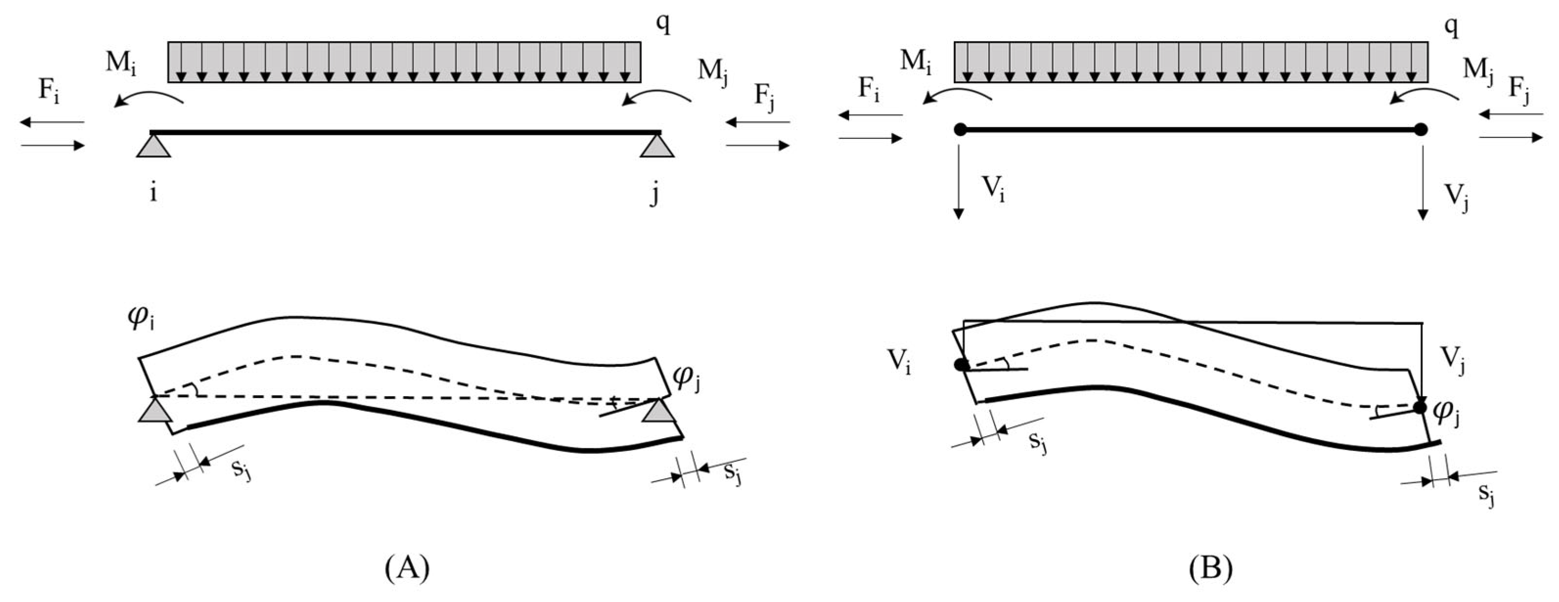
As shown in previous studies [
19,
20,
21], each node of the two-layer composite beam element, as illustrated in
Figure 1, is associated with three degrees of freedom: the vertical displacement (
v), the cross-sectional rotation (
φ), and the interlayer slip (
s). These generalized displacements are defined for both ends of the element, enabling the model to independently capture the bending and axial behaviors of the concrete and timber/bamboo layers. This configuration results in a total of six degrees of freedom per element. By explicitly modeling the interlayer slip, the formulation allows for the simulation of partial composite action, which is essential for accurately reproducing the behavior of timber-concrete and bamboo-concrete composite beams.
Figure 1A illustrates the simply supported beam configuration used for the flexibility-based (force-based) element, where unit loads generate nodal displacements and slips.
Figure 1B represents the unrestrained beam adopted in the displacement-based formulation, in which nodal forces arise from imposed deformations. The internal nodal forces include the vertical shear force (V), bending moment (M), and interfacial shear force (F). These are related to the generalized displacements via the element stiffness matrix, which is assembled and iteratively updated during nonlinear analysis. The nodal configuration enables the model to respond to different connection behaviors—ranging from ductile to brittle—depending on the results of the push-out tests. This structural representation, which incorporates both material and interface nonlinearities, is critical for evaluating the full range of composite action and the development of failure mechanisms along the beam.
2.3. Nonlinear Analysis
The proposed model accounts for three key nonlinear phenomena that govern the flexural behavior and failure mechanisms of timber–concrete and bamboo–concrete composite beams:
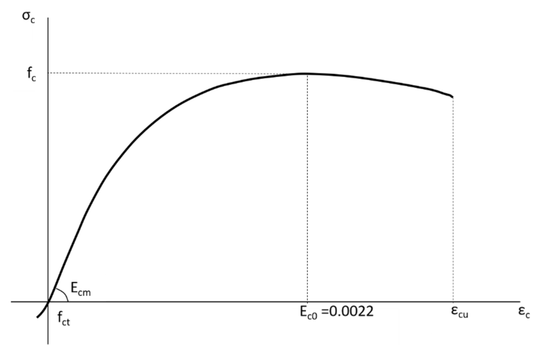
Concrete behavior in compression and tension is represented using a nonlinear constitutive model (
Figure 2). The compressive response is modeled according to the formulation proposed by Saenz [
22], which captures the gradual stiffness degradation and softening beyond the peak stress. In contrast, the tensile behavior is modeled as linear elastic up to the tensile strength (f
ct), followed by a sudden loss of stress-carrying capacity, characterizing a brittle failure. This elastic–brittle law reflects the cracking behavior typically observed in concrete under tension. The key parameters include the tensile strength, secant modulus (E
cm), ultimate strain (ε
cu), and maximum compressive strength (f
c);
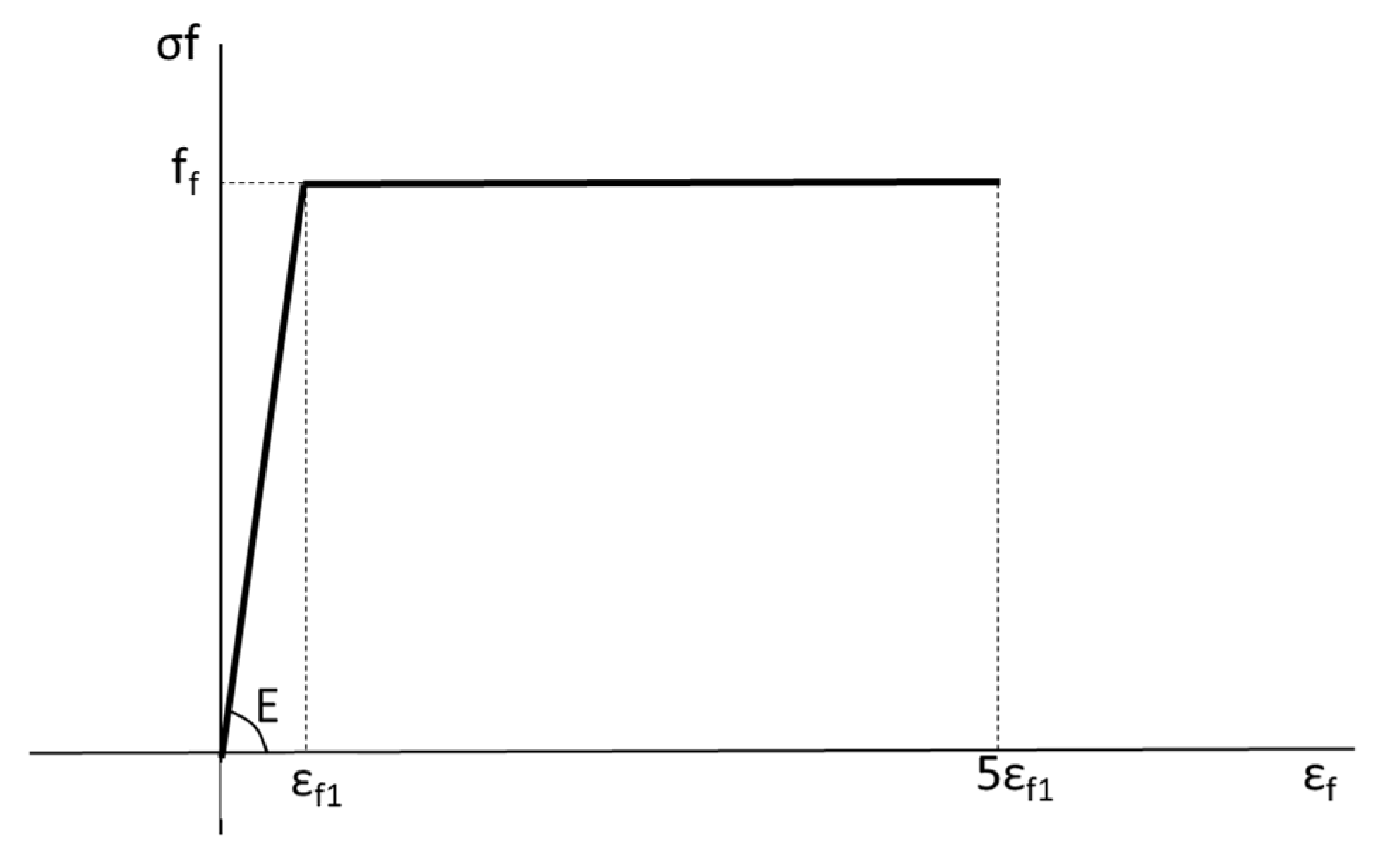
Elastic–plastic behavior of timber and bamboo governs the deformation response of the tensile layer. The stress–strain relationship is defined by an initial linear segment followed by perfect plasticity (
Figure 3). The model uses the modulus of elasticity (E), maximum flexural strength (f
f), and elastic strain limit (ε
f1) as primary input parameters;
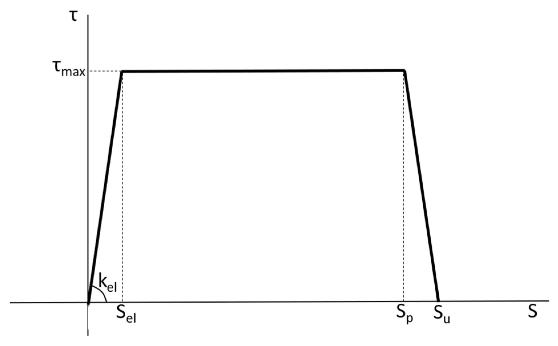
Connection behavior is modeled using a tri-linear shear–slip law derived from experimental push-out test data (
Figure 4). This formulation captures the progressive degradation of composite action, with parameters including elastic connection stiffness (k
el), peak interface shear stress (τ
max), the characteristic slip values at the elastic limit (s
el), and peak (s
p) and ultimate slip (s
u).
The mechanical parameters adopted for timber, bamboo, concrete, and interface connections were directly extracted or inferred from the experimental studies used in model validation. For concrete, compressive strength values ranged from 22 MPa to 47 MPa, depending on the use of lightweight or conventional concrete. Corresponding secant moduli and ultimate compressive strains were assigned accordingly. Tensile strength was considered as 10% of the compressive strength in the absence of direct measurements. For timber/bamboo elements, elastic moduli ranged from 9400 to 16,810 MPa. Ultimate tensile strains were also based on reported data and curve fitting to flexural responses.
Connection properties—including elastic stiffness, peak interface shear stress, and slip capacities—were all obtained from corresponding push-out tests reported in each study. This approach ensured internal consistency between the mechanical behavior of the materials and the connection system and the numerical predictions. The mechanical properties used for each beam, including materials and connectors, are summarized in
Table 1.
2.4. Model Validation
Validating the proposed numerical model is essential to assess its predictive capability in simulating the flexural behavior of timber–concrete and bamboo–concrete composite beams. To ensure this, a dataset comprising 17 beams from existing literature was selected based on specific criteria. Only studies that provided both flexural test results and push-out tests characterizing the connection properties were considered. Additionally, composite beam studies that cited push-out test data from prior publications were included when the connection characteristics were consistent. This careful selection ensured that the mechanical properties used in the numerical model were representative of the actual test conditions.
The behavior of composite beams is highly sensitive to the properties of the concrete and timber/bamboo layers, as well as the characteristics of the connection system. Even minor variations in these parameters can significantly affect model accuracy. Consequently, incorporating connection properties obtained from unrelated studies with different material combinations can compromise model fidelity. By prioritizing studies in which flexural and push-out tests were conducted under the same experimental framework, the internal consistency of the validation process was preserved.
The selected beams encompass a variety of materials—including lightweight and conventional concrete (reinforced and unreinforced), timber, bamboo, cross-laminated timber (CLT), and glued laminated bamboo (glubam)—with different connection types and spacing configurations. This diverse dataset allows the model to be evaluated across a wide range of geometries and mechanical conditions, thereby demonstrating its versatility in simulating the complex interactions within composite beams.
A similar methodology was previously adopted in the validation of models for FRP-strengthened beams, in which four-point bending tests from the available literature were analyzed to evaluate model accuracy [
21]. In this study, the goal is to demonstrate the effectiveness of the model in reproducing the flexural behavior and failure mechanisms of TCC and BCC beams. This is accomplished by comparing the numerical predictions with experimental data from the literature, focusing on key performance indicators such as load–displacement and load–slip curves, as well as failure modes including concrete cracking and rupture of bamboo/timber or connections.
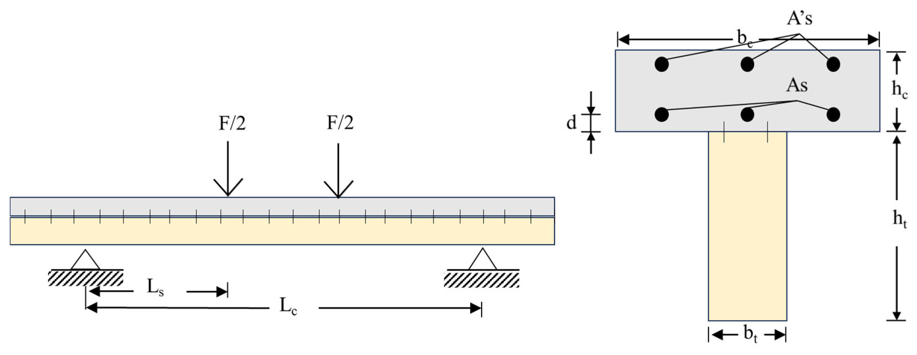
Figure 5 illustrates a typical configuration of the four-point bending tests used in the validation process. In this setup,
Lc denotes the clear span of the beam and
Ls is the distance from the support to the load application point. The timber or bamboo layer has a width
bt and height
ht, while the concrete layer has a width
bc and height
hc. The vertical distance from the center of the reinforcement to the bottom surface of the concrete is
d. The reinforcement areas are indicated as
As for the bottom and
A’s for the top reinforcement, respectively.
Table 2 provides the geometric and mechanical properties of the beams analyzed, including details on beam span, cross-section dimensions, connection type, connector size, and spacing.
Table 1 summarizes the material properties used in each study, along with the type of push-out test conducted.
To clarify the notation used in the tables, the following abbreviations apply:
D = diameter of the dowel or screw (mm);
W = width of the notch (mm);
Lc = connector length for dowels and screws (mm);
Sp = spacing between connectors (mm);
L = lightweight concrete;
C = conventional concrete;
fc = compressive strength of concrete (MPa);
E = elastic modulus of timber, bamboo, or glubam (MPa).
The beams in the dataset exhibit a wide range of geometrical configurations. The height-to-width ratio (h/b) of the concrete section ranges from 0.11 to 0.35, while for the timber/bamboo section; it varies from 0.27 to 3.39. The ratio of the height of the timber/bamboo section to the concrete layer height ranges from 2.0 to 3.8. Clear span lengths range between 2400 mm and 7800 mm.
Connector diameters vary from 6 mm to 18 mm, with lengths ranging from 50 mm to 190 mm [
4,
5,
15]. Notched connectors are typically 100 mm or 200 mm wide, with depths of either 25 mm or 50 mm [
5,
24]. The experimental stiffness values of the connections were obtained from push-out tests reported in each study and incorporated into the numerical simulations. When multiple stiffness values were provided, the model utilized K₀.₆, defined as the average secant modulus at 60% of the ultimate load, for consistency in comparison [
12,
15].
The beams were fabricated using both prefabrication and cast-in-place methods. In prefabricated specimens, bamboo, glubam, or timber beams were fitted with dowels inserted into pre-drilled holes and secured with adhesive. The concrete portion was then precast with openings to accommodate the beam and assembled with grout for integration [
5,
15]. For cast-in-situ beams, dowels were inserted into the bamboo beam, and a concrete slab was cast over the assembly using formwork [
4,
15]. In notched-only connections, notches were carved into the lower section of the CLT panel, onto which concrete was directly poured [
24].
All numerical simulations employed the same nonlinear material and connection models presented earlier (
Figure 2,
Figure 3 and
Figure 4), ensuring consistency across the validation process.
3. Results and Discussion
To evaluate the predictive accuracy of the proposed model, a representative dataset comprising 17 experimental cases of composite beam bending behavior was compiled from the literature [
4,
5,
15,
23,
24]. These studies were selected based on the availability of both flexural test results and corresponding push-out tests, ensuring consistency in connection characterization. Although load–deflection curves for all cases are not individually presented to maintain conciseness, their corresponding values are summarized in
Table 3.
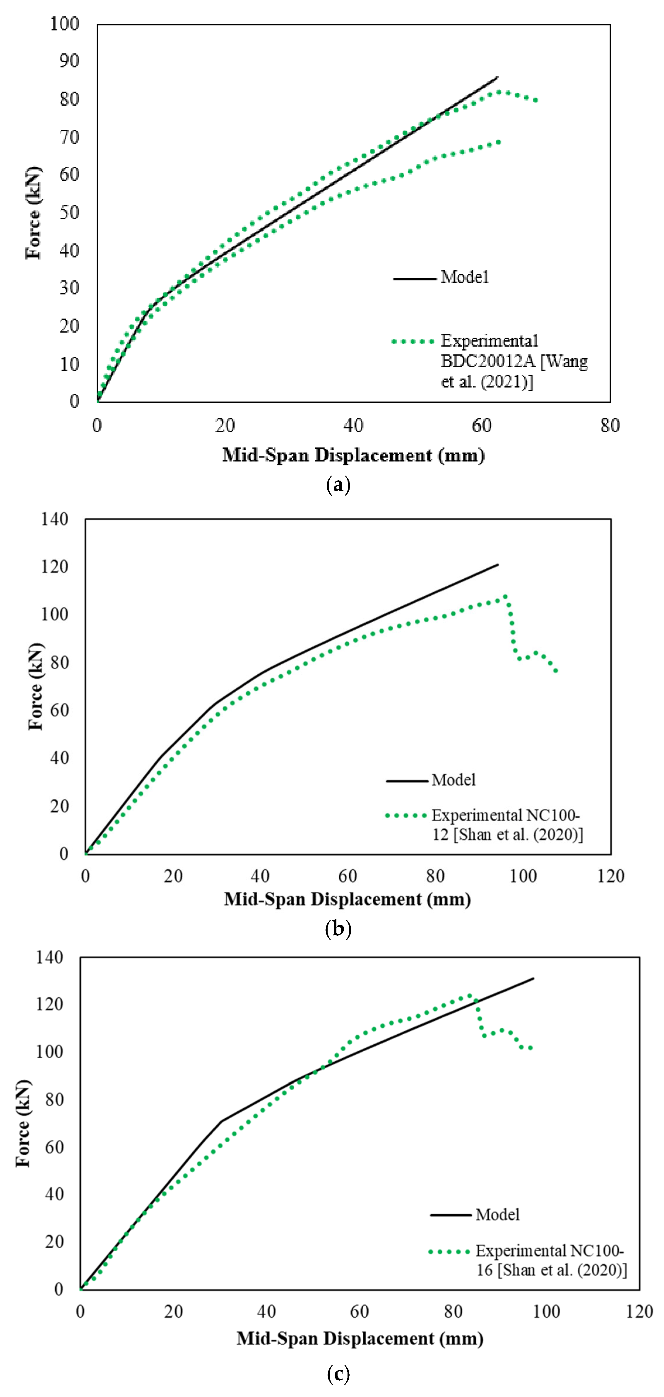
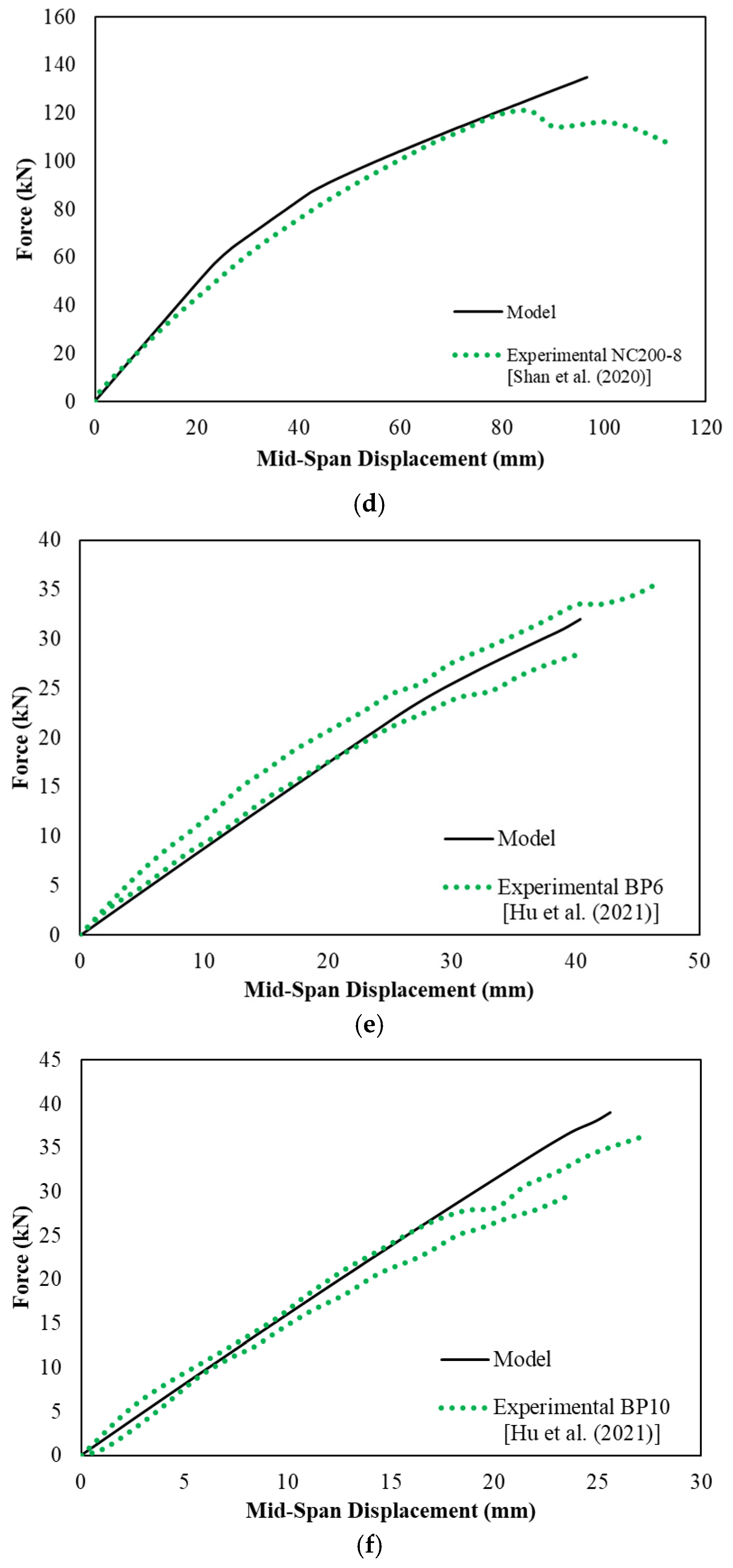
Overall, the model demonstrates very good alignment with the experimental data, particularly within the initial linear-elastic regime of the load–deflection curves. This reflects the model’s ability to accurately predict the initial stiffness and early-stage behavior of the beams. This observation is consistent with previous modeling approaches for composite beams, such as those reported by Gutkowski et al. [
7] and Appavuravther et al. [
2], where initial stiffness was also governed primarily by connection stiffness. These initial responses, largely governed by the linear stiffness of the connections, underscore the critical importance of accurate push-out testing. The push-out tests provided well-characterized input parameters, such as the elastic stiffness (kel), ensuring reliable simulation of early composite action.
In the moderate displacement range, the model continues to closely follow experimental trends. However, at larger displacements—where material nonlinearities, damage accumulation, and failure mechanisms begin to dominate—some divergence between numerical and experimental curves becomes evident. In particular, the model tends to slightly overestimate load capacity in the post-linear phase. This overestimation is more pronounced when the experimental response shows stiffness degradation or softening due to cracking in concrete and timber or bamboo and yielding in the connections [
1,
15]. In several cases, this can be attributed to the absence or simplification of certain material parameters (e.g., ultimate strains for concrete and timber/bamboo), which play a critical role once nonlinear behavior becomes predominant.
It is important to note that as the response transitions from elastic to nonlinear, the contribution of the connections diminishes, and the behavior becomes increasingly dependent on the material properties of the concrete and the timber/bamboo. Moreover, as also highlighted by Wang et al. [
15], some modeling approaches may fail to incorporate key nonlinearities, such as compressive softening in timber, bamboo, and concrete, concrete cracking, and shear softening of the connectors. Therefore, the precise characterization of the compressive and tensile properties of both layers—including post-peak softening and damage parameters—is essential to improve the model’s performance in this regime. Shan et al. [
5] also observed that under high load levels or near failure, glubam–concrete composite beams exhibited a significant stress discontinuity at the interface, as well as separate neutral axes for each material layer, indicating a loss of full composite action. Some experimental curves also exhibit abrupt force drops, indicating localized failures such as shear plug formation or brittle fracture, which the model captures more gradually. This is a typical limitation of continuum-based finite element models that do not explicitly simulate localized damage propagation [
24].
Despite these deviations in the post-peak region, the model performs well in capturing critical structural indicators, such as initial stiffness, peak load, and general failure mode. These aspects are essential for both design and reliability analysis, and the observed differences remain within acceptable engineering tolerances. The model’s ability to simulate composite action up to failure highlights its robustness for structural assessment purposes.
Importantly, the model also succeeds in predicting the mode of failure—whether by concrete crushing, timber/bamboo rupture, or connection failure—based on predefined material and interface failure criteria. The predicted failure mode, identified by a failure flag during simulation, was then directly compared with the failure mode reported in each experimental study. The results are summarized in
Table 3. This predictive capability enhances the practical value of the model by enabling the design of beam configurations that promote desirable failure mechanisms through adjustments in geometry, material properties, or connector layout.
Figure 6 presents comparisons between experimental and numerical load–deflection responses for six representative beams. The solid black lines denote the model predictions, while the green dotted lines represent experimental data. These curves illustrate the model’s ability to capture overall stiffness and deformation trends.
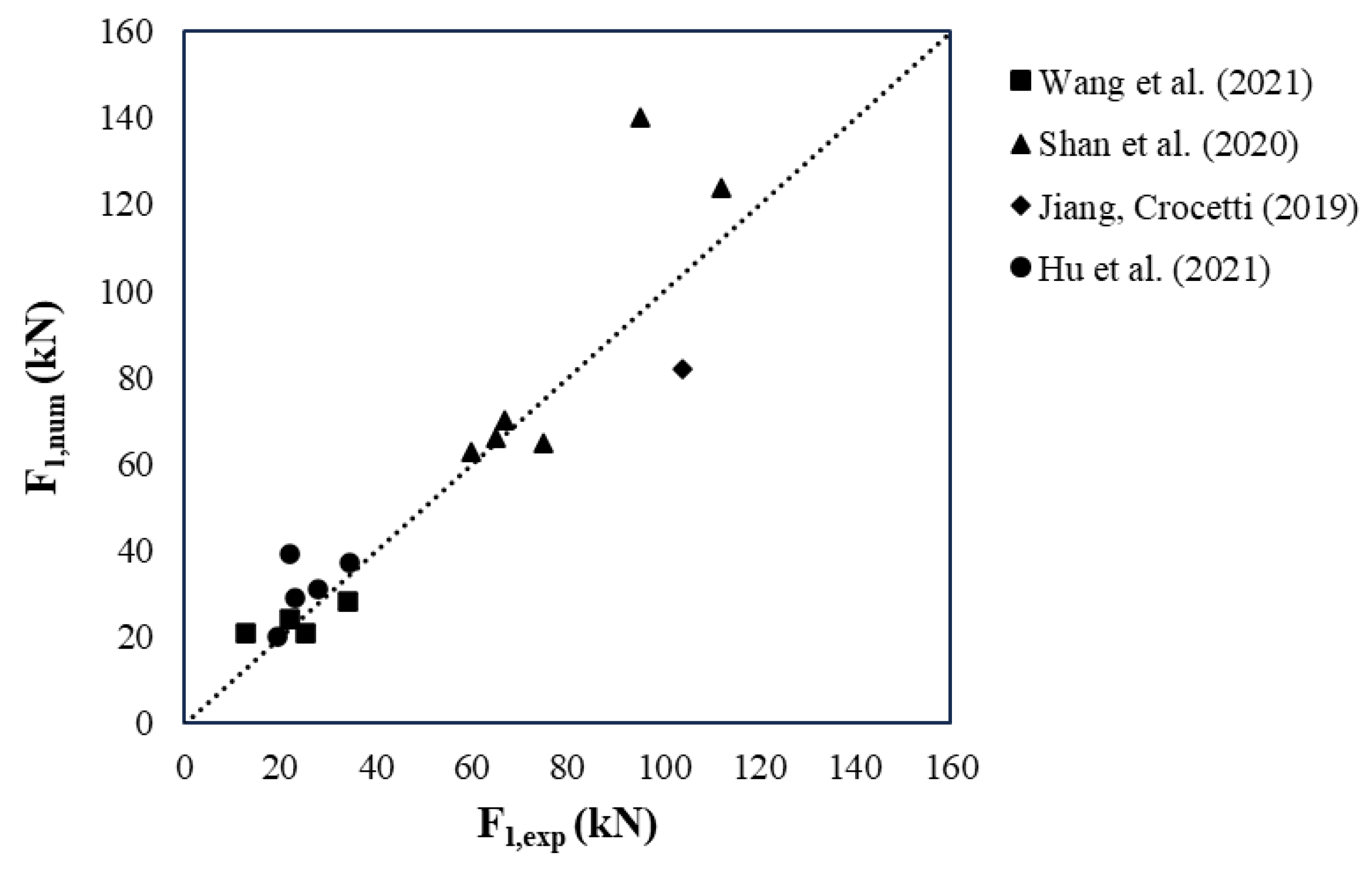
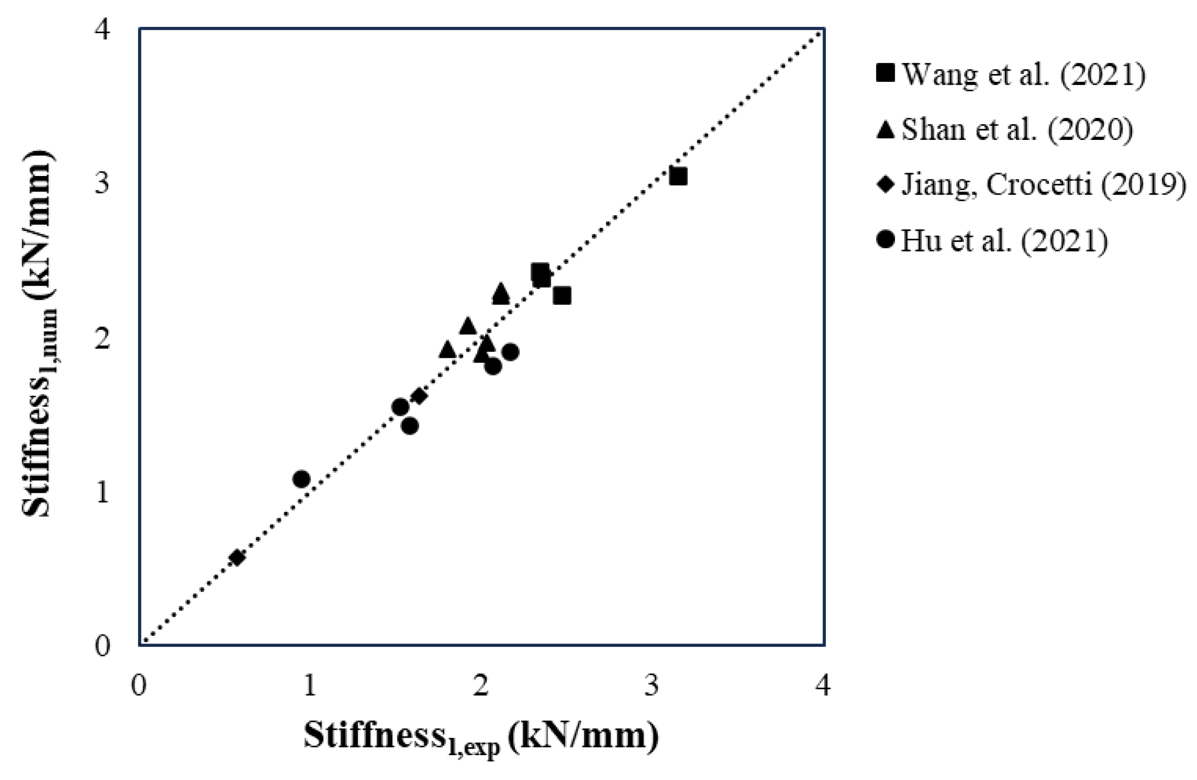
To quantitatively assess the model’s performance in the linear range, comparisons were made between experimental and numerical values for three key indicators: the maximum load in the elastic range (Fl), the corresponding mid-span deflection, and the initial stiffness. These comparisons are illustrated in
Figure 7,
Figure 8 and
Figure 9.
Figure 7 presents the comparison between the experimental and numerical values of the maximum load in the linear range. The dashed line represents the ideal correlation line (y = x), indicating perfect agreement between model predictions and test results. Most data points are distributed closely around this line, suggesting that the model reliably estimates the linear load-bearing capacity of composite beams. However, certain deviations are noted. For example, beam SC-45 [
15] exhibited a 47% overestimation (140.00 kN numerical vs. 95.00 kN experimental), which may be attributed to simplifications in modeling post-yield behavior or underestimation of slip effects at the interface. In contrast, beam BP6 [
4] shows nearly perfect agreement, demonstrating that when input parameters are well characterized, the model can yield highly accurate predictions.
These results are consistent with trends observed in previous studies [
5,
15], which also reported increased deviations near failure due to limitations in capturing nonlinearities and interface degradation. Despite these challenges, the model demonstrated consistent accuracy: 68.75% of the beams showed deviations below 20%, and 81.25% remained within 30%. This level of agreement reinforces the model’s reliability across different configurations. Notably, this performance is superior to that reported in studies using the γ-method, which overestimated load-bearing capacity and stiffness by approximately 40% compared to experimental results [
1]. These findings highlight the enhanced predictive capability of the nonlinear finite element approach adopted in this study.
Figure 8 shows the relationship between experimental and numerical mid-span deflections at the Fl level. The results follow the identity line with acceptable dispersion, confirming the model’s ability to estimate global displacements in the elastic range. A closer analysis reveals that 50% of the beams presented differences below 20%, and 75% were within 30% of deviation. In some cases, deviations can be explained by uncertainties in boundary conditions, geometric imperfections, or the influence of unmodeled local deformations near the supports. Additionally, small inaccuracies in input parameters such as modulus of elasticity or connector stiffness may significantly affect the predicted displacement, even more than the load-bearing capacity. These results are consistent with those reported in [
12], which found greater deviation in mid-span displacement at the ultimate limit state compared to the serviceability limit state, attributing this to the assumption of linear elasticity, which prevents accurate estimation of effective stiffness beyond the serviceability limit state.
Figure 9 presents the comparison between experimental and predicted initial stiffness values. The data distribution shows excellent agreement, with most points lying very close to the identity line, highlighting the model’s reliability in capturing stiffness across a wide range of materials and connection types. For instance, beam F1 [
24] exhibited a perfect match (0.57 kN/mm), while beam BP12 [
4] showed a modest underestimation of 13%. These results highlight the model’s ability to reproduce elastic behavior when accurate material parameters and connection stiffness are provided.
Quantitatively, 87.5% of beams had stiffness deviations below 10%, and all cases remained within a 30% error margin, demonstrating the robustness of the model in elastic stiffness prediction.
Table 3 provides a detailed comparison between experimental and numerical results across all 17 beams, detailing stiffness, linear load (Fl), deflection at Fl, and failure mode. The model demonstrates strong predictive capability not only in capturing the magnitude of the structural response but also in correctly identifying the failure mechanism—whether concrete crushing (CC), glubam rupture (GR), cross-laminated timber rupture (CR), or timber rupture (TR). This ability to replicate failure mechanisms enhances the model’s utility in practical applications, as it allows engineers to evaluate and optimize beam configurations with respect to both performance and safety.
In addition to global response metrics, localized phenomena such as slip at the supports were also evaluated.
Figure 10 presents the load–slip curves at the beam supports, comparing experimental and numerical results. The model effectively captures the initial slip behavior, governed by the linear connection stiffness, and reflects the progression of interface slip with reasonable accuracy.
In
Figure 10a, which illustrates a bamboo–lightweight concrete beam, the model closely follows the ascending branch of the curve, though it slightly underestimates slip beyond the peak load. This deviation likely stems from simplified assumptions regarding post-peak degradation of the connection.
Figure 10b, for a glubam–concrete beam, exhibits similar trends, with satisfactory agreement in the elastic range and minor divergence as nonlinearity increases. In both cases, discrepancies may also be influenced by experimental uncertainties, particularly in slip measurements that are highly sensitive to instrumentation and support conditions.
Ultimately, despite some divergence in the post-linear domain—especially when predicting softening or abrupt failure—the model exhibits consistent and reliable performance across different material combinations and connection configurations. Its ability to predict stiffness, load capacity, deformation, and failure mode underscores its applicability as a robust tool for the design and analysis of hybrid structural systems based on timber, bamboo, and concrete.


 ,
, 


