1. Introduction
As infrastructure systems face mounting demands related to complexity, scale, and sustainability, there is an urgent need to adopt emerging digital technologies that can support more efficient, integrated, and intelligent project delivery. The growing pressure on critical sectors, such as ports and waterways, to modernise and digitise processes reflects broader industry trends toward data-driven decision-making, lifecycle asset management, and collaborative design. In this context, technologies, such as semantic modelling, data-centric workflows, and open standards, are transforming how infrastructure is planned, built, and operated. These developments are particularly valuable in domains where the limitations of traditional tools limit effective coordination, scalability, and long-term performance.
The digital transformation of the Architecture, Engineering, and Construction (AEC) industry has elevated data interoperability and standardisation as critical enablers of efficiency, collaboration, and resilience in complex infrastructure systems [
1,
2]. As infrastructure projects grow in technical and organisational complexity, the ability to exchange structured data across disciplines, platforms, and lifecycle stages is increasingly essential [
3,
4]. In this context, openBIM, a vendor-neutral, standards-driven approach, is gaining traction for its potential to ensure consistent, transparent, and reusable data flows throughout project lifecycles [
5].
At the core of openBIM lies the Industry Foundation Classes (IFCs) schema, widely recognised for its role in encoding and sharing building and infrastructure information. The release of IFC 4.3 represents a paradigm shift, significantly expanding the schema’s scope to include infrastructure domains such as roads, railways, bridges, and—critically—ports and waterways [
6,
7,
8,
9]. This extension introduces advanced spatial constructs and domain-relevant entities that offer new opportunities for modelling maritime infrastructure in a semantically rich and interoperable manner. Despite these advancements, the application of IFCs in the port and waterway sector remains underexplored. This sector features a wide array of assets, berths, docks, ship locks, breakwaters, and dredging zones that demand interdisciplinary coordination among engineers, hydrologists, environmental scientists, and regulatory bodies. Existing BIM tools often rely on proprietary schemas, resulting in semantic mismatches, information loss, and workflow inefficiencies during data exchange [
10,
11,
12,
13,
14].
While previous studies have proposed extending IFCs to accommodate infrastructure-specific needs, few have examined the untapped potential of leveraging the current IFC schema through semantic reinterpretation and alignment. This research addresses this gap by proposing a structured framework that enables practitioners to use existing IFC constructs for port infrastructure modelling, without requiring schema extensions. Unlike prior approaches that focus on schema extensions, this framework demonstrates how the semantic reinterpretation of the data schema can sufficiently accommodate complex maritime use cases. This lightweight, standards-compliant strategy provides a scalable alternative that supports interoperability without adding to the schema overhead. Two key objectives guide the research:
To assess the applicability of IFCs for representing port and waterway infrastructure, identifying relevant entities, attributes, and relationships that align with domain-specific semantics and workflows.
To validate the schema’s performance through two real-world case studies, demonstrating how IFCs can support federated modelling, multidisciplinary coordination, and lifecycle data exchange in maritime contexts.
To address these, this study proposes a framework that leverages the semantic interpretation of existing IFC constructs, rather than relying on schema extensions, to improve interoperability within the port and waterway sector. In particular, the lack of domain-specific property sets (Psets) and standardised classifications is identified as a core barrier to structured information exchange in this context. The findings inform technical guidelines and propose future directions in semantic enrichment, GIS-BIM integration, and digital twin deployment. The paper is structured as follows:
Section 2 presents a state-of-the-art review on the adoption of openBIM, data exchange challenges, and the application of IFC 4.3 in infrastructure projects.
Section 3 outlines the methodology used to evaluate the applicability of schemas, workflow alignment, and real-world performance.
Section 4 details the conceptual modelling, implementation strategies, case study insights, and recommendations for standardisation. The conclusion is given in
Section 5. To provide a clearer overview of the research structure and methodological flow,
Figure 1 presents a high-level workflow diagram summarising the key phases of the study, from conceptual modelling to case study validation and recommendations.
3. Methodology
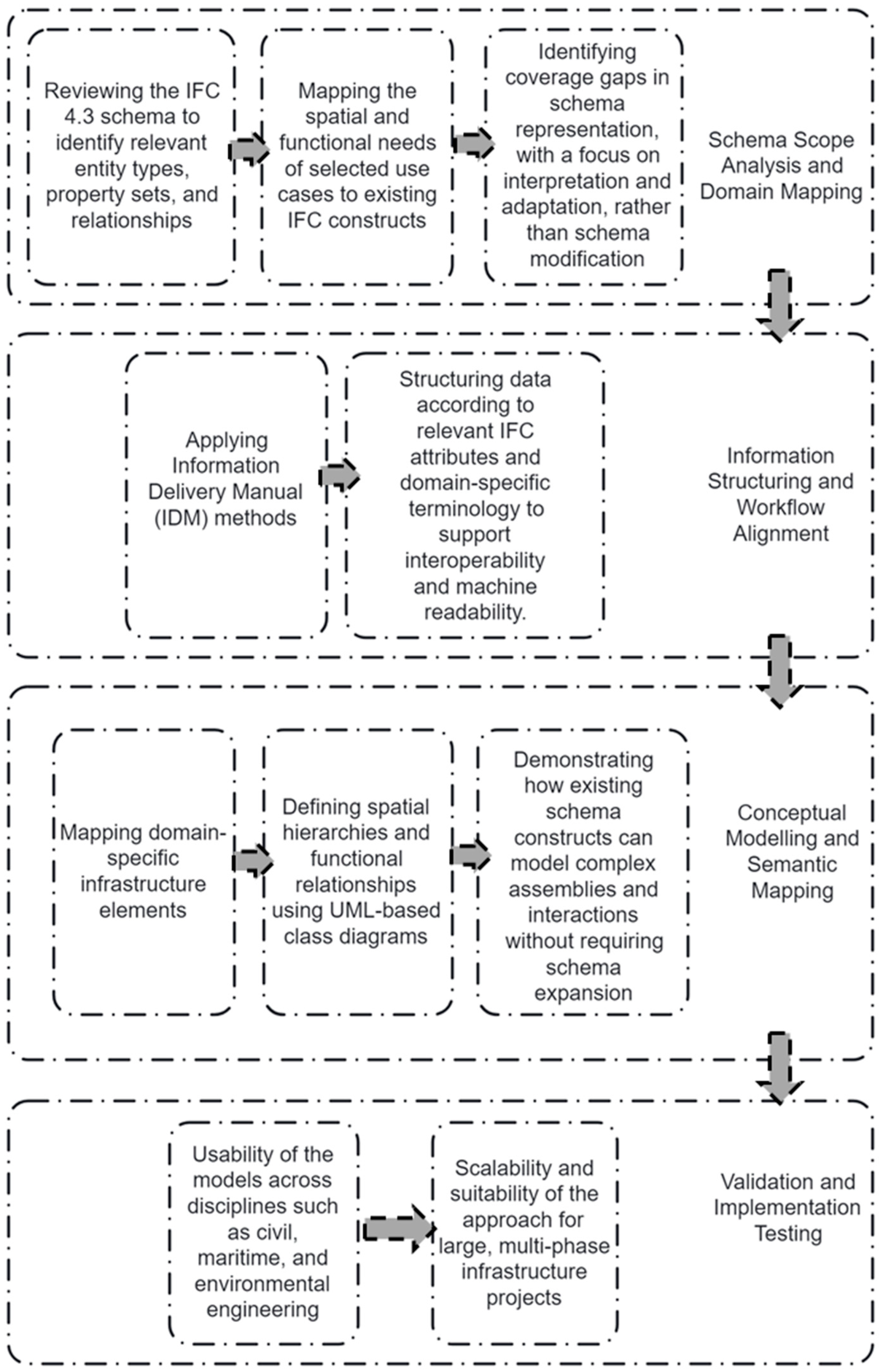
This study adopts a structured, multi-phase methodology to evaluate the semantic adequacy, implementation feasibility, and interoperability performance of the IFC schema in the context of port and waterway infrastructure. The overarching aim is to assess how effectively existing IFC constructs can support domain-specific data requirements and interdisciplinary collaboration, without the need for schema extensions. The methodology is organised into four interrelated components (
Figure 4), each contributing to a cumulative assessment of the schema’s applicability across planning, design, and operational phases.
3.1. Schema Scope Analysis and Domain Mapping
The first phase establishes the foundation for semantic modelling by analysing the scope of IFCs in relation to maritime infrastructure requirements. Representative use cases, such as shipyards, docks, lock chambers, and dredging zones, are selected to reflect the sector’s spatial and functional diversity. Key activities include the following: (1) Reviewing the IFC 4.3 schema to identify relevant entity types, property sets, and relationships. (2) Mapping the spatial and functional needs of selected use cases to existing IFC constructs. (3) Identifying representation gaps, focusing on schema interpretation and adaptation, rather than modification. This phase builds a knowledge base for developing a semantically aligned modelling strategy designed for maritime infrastructure.
3.2. Information Structuring and Workflow Alignment
The second phase focuses on aligning domain-specific information needs with openBIM workflows and structured data delivery protocols. This involves the following: (1) applying IDM principles to define the who, what, when, and why of information exchanges across project phases; (2) structuring data according to relevant IFC attributes and domain-specific terminology; (3) defining information granularity in accordance with project stage and discipline needs, supporting machine-readable validation and semantic consistency. This phase ensures that maritime-specific data, such as environmental attributes, functional zones, and operational conditions, can be exchanged across tools and stakeholders.
3.3. Conceptual Modelling and Semantic Mapping
The third phase develops a conceptual semantic model that interprets and adapts IFC constructs to represent port and waterway infrastructure in a semantically rich and interoperable way. Key activities include the following: (1) Mapping domain-specific components (e.g., quay walls, fender systems, lock gates) to IFC entities using an object-oriented analysis. (2) Defining spatial hierarchies (e.g., facilities, facility parts, spatial zones) and functional relationships using UML-based class diagrams. (3) Establishing semantic links between physical components, environmental conditions, and operational systems. (4) Demonstrating how existing schema constructs can model complex assemblies and interactions without requiring schema expansions.
3.4. Validation and Implementation Testing
The final phase involves practical validation through two pilot case studies, developed in collaboration with industry stakeholders, to assess the real-world applicability across the project stages. The first case study focused on a shipyard master planning model, representing an early-stage planning scenario characterised by a low level of development (LOD). This model emphasised spatial layout, infrastructure zoning, and environmental integration, providing a testbed for evaluating the schema’s support for conceptual design and planning workflows. The second case study featured a ship lock design coordination model, which addressed detailed design and interdisciplinary coordination requirements. This model involved complex spatial hierarchies and detailed representations of structural, mechanical, and environmental systems, reflecting the high-resolution demands of advanced infrastructure projects.
The validation was conducted using three primary metrics: (1) modelling the completeness and semantic clarity of the IFC-based representations; (2) the usability of the models across disciplines such as civil, maritime, and environmental engineering; and (3) the scalability and suitability of the approach for large, multi-phase infrastructure projects. These metrics provided a comprehensive basis for assessing the effectiveness of IFC 4.3 in supporting structured, interoperable, and lifecycle-aware modelling practices in the port and waterway domain.
4. Semantic Modelling and Application of IFCs in Port and Waterway Projects
Port and waterway infrastructure projects are typified by their spatial complexity, multidisciplinary scope, and environmental interdependencies. Facilities such as shipyards, navigation locks, berthing zones, and dredging areas involve a wide variety of asset types, functional groupings, and operational systems. These elements must be represented in a digital framework that supports semantic clarity, spatial hierarchy, and environmental integration across the full lifecycle of the asset. This section evaluates the capability of the BIM data schema to address these requirements through semantic alignment, focusing on how its core constructs can be applied, without modification, to the modelling needs of the ports and waterways domain.
4.1. Semantic Mapping and Exchange Workflows for Port and Waterway Infrastructure
To effectively manage the spatial, functional, and environmental complexity inherent in port and waterway infrastructure, the application of a structured semantic modelling approach becomes essential. The IFC schema, particularly in its 4.3 extension, is uniquely positioned to support these requirements without customization. A key requirement in this domain is the ability to represent spatial and functional hierarchies in a manner that facilitates both design coordination and lifecycle information management. IFCs introduce a refined spatial breakdown structure that enables the modelling of nested infrastructural components. At the highest level, IfcSite defines the project context, while IfcFacility captures major infrastructure systems, such as shipyards or ship locks. These are further decomposed using IfcFacilityPart, which represents components such as berthing areas, lock chambers, or approach channels. Within these subdivisions, IfcSpace allows for the detailed modelling of enclosed functional areas, including control rooms, pump stations, or maintenance corridors. In parallel, IfcZone supports the grouping of non-contiguous spaces based on operational or regulatory logic, such as safety zones or sediment maintenance areas. These spatial elements are interlinked through standard IFC relationships—most notably IfcRelAggregates, which defines hierarchical containment, and IfcRelContainedInSpatialStructure, which assigns physical components to spatial containers. This structure enables a top-down, semantically coherent representation of maritime facilities, supporting both design development and asset management.
In addition to spatial representations, port infrastructure requires the detailed modelling of physical components and mechanical systems. IFC 4.3 provides a range of domain-relevant entities for maritime applications, including IfcMarineFacility, IfcMooringDevice, and IfcTransportElement. These entities are further refined using predefined type enumerations, such as IfcMarineFacilityTypeEnum and IfcFacilityPartCommonTypeEnum, which allow for the classification of infrastructure as ports, shipyards, or ship locks and their subcomponents as berthing structures, approach basins, or lock gates. The schema also includes an array of property sets that can be associated with these entities to enrich their semantic content. For example, Pset_ShipyardCommon and Pset_ShiplockDesignCriteria provide structured parameters, such as dock dimensions, flow capacities, and operational constraints. These properties are essential for supporting design decisions, performance analysis, and regulatory compliance
Beyond the built environment, port infrastructure must account for dynamic environmental systems that influence infrastructure performance and maintenance. These include tidal fluctuations, sediment transport, water quality, and hydrodynamic cycles. Although IFCs are traditionally focused on constructed assets, they introduce mechanisms to accommodate external environmental conditions. The IfcExternalSpatialElement entity is particularly relevant, allowing for the modelling of natural zones, such as tidal basins, sediment beds, and floodplains. This entity can be extended with property sets, such as Pset_EnvironmentalCondition, to include data on tidal ranges, water salinity, sediment composition, and other environmental parameters. Moreover, geological and hydrological strata can be represented using IfcSolidStratum and IfcWaterStratum, providing a layered depiction of subsurface and aquatic conditions. These entities enable the integration of natural systems directly into the BIM environment, supporting planning workflows that require environmental sensitivity and operational resilience.
Taken together, the evaluations demonstrate that the BIM data schema provides a robust semantic framework for addressing the core modelling requirements of the ports and waterways domain. The schema enables the decomposition of infrastructure into spatial and functional hierarchies, the detailed representation of physical components, and the integration of environmental data without requiring additional schema extensions. This capability positions IFCs as viable standards for developing interoperable, lifecycle-oriented digital models of maritime infrastructure. The following section builds upon this foundational analysis by mapping representative use cases to corresponding IFC constructs, further demonstrating the schema’s practical coverage and adaptability.
These modelling strategies are not only theoretical but have been validated through real-world applications.
Section 4.5 presents two representative case studies that demonstrate the implementation of these schema mappings in actual port and shipyard projects.
4.2. Mapping Domain Use Cases to Data Schema
To evaluate the applicability of IFCs to port and waterway infrastructure projects, this section presents a set of representative use cases and systematically maps their semantic and functional requirements to existing IFC constructs. The aim is to assess the extent to which the current schema can support domain-specific modelling needs without necessitating schema extensions. This mapping process also serves to validate the schema’s structural and semantic alignment with critical infrastructure components, workflows, and environmental contexts.
The selected use cases reflect the diverse operational and spatial characteristics inherent to maritime infrastructure. These include infrastructure-intensive systems, such as ship locks, comprising chambers, control rooms, flow regulation systems, and navigation channels, as well as shipyard facilities, which integrate dry docks, repair workshops, logistics zones, and administrative areas. In addition, large-scale port expansion projects are considered, with an emphasis on berthing areas, dredging zones, cargo terminals, and multimodal transport integration. Each use case is analysed in terms of its spatial decomposition, physical components, environmental integration, and functional groupings. These elements are then mapped to relevant IFC entities, attributes, and relationships.
The schema’s spatial hierarchy supports the representation of complex port infrastructure using a combination of IfcFacility, IfcFacilityPart, IfcSpace, and IfcZone. For example, in the case of a ship lock system, the overall lock infrastructure is modelled as an IfcFacility, with the chambers, guide walls, and lead channels represented as IfcFacilityPart entities. Enclosed rooms, such as control cabins and machinery rooms, are assigned to IfcSpace, while maintenance and safety zones are defined using IfcZone. Surrounding natural features, including approach channels and floodplains, are modelled using IfcExternalSpatialElement. These spatial structures are linked through IfcRelAggregates for hierarchical decomposition and IfcRelContainedInSpatialStructure for spatial containment, enabling a semantically consistent representation of both physical and operational domains.
The physical elements within these use cases are represented using appropriate subtypes of IfcProduct, supported by domain-relevant classifications. Lock gates and wall structures are modelled using IfcBuildingElement, while mechanical and hydraulic systems such as pumps, valves, and actuators are represented through IfcDistributionFlowElement. Electrical control systems, lighting, and signalling infrastructure are captured using IfcDistributionElement and IfcElectricalElement. Additional marine-specific components, including bollards, fenders, and mooring devices, are incorporated using generic types, such as IfcElement or IfcTransportElement, with the semantic specificity added through property sets and classification references. These elements are grouped functionally using IfcRelAssignsToGroup and linked to service relationships via IfcRelServicesBuildings.
Environmental and operational data, essential to the performance and maintenance of maritime infrastructure, are integrated using IfcExternalSpatialElement in conjunction with custom or predefined property sets. For instance, tidal variation, sediment transport, and flow velocity are modelled as properties of natural spatial zones or hydraulic systems. Where predefined property sets are insufficient, custom property definitions are used while maintaining schema compliance. This approach allows for contextual parameters, such as sedimentation rates, dredging intervals, and water quality indicators, to be embedded directly into the IFC model, supporting resilience planning and environmental monitoring.
Table 1 and
Figure 5 provides detailed mapping between ship lock components and corresponding IFC entities, illustrating how spatial, physical, environmental, and relational elements are semantically structured. Similar mapping strategies were applied to shipyard and dry dock facilities. In these contexts, the entire facility is modelled as an IfcMarineFacility, with dry dock basins, pump rooms, and access areas assigned to IfcFacilityPart and IfcSpace. Physical components, such as dock gates, cranes, and pumping systems, are represented using combinations of IfcBuildingElement, IfcTransportElement, and IfcDistributionSystem. Operational zones, such as fuelling stations, customs clearance areas, and safety buffers, are structured using IfcZone, enabling the representation of both functional and regulatory groupings within the digital model.
The semantic coverage analysis confirms that IFCs possess sufficient flexibility to support the decomposition of maritime infrastructure into functionally meaningful and spatially coherent units. The integration of environmental features, while requiring careful property assignment, is achievable within the schema’s current structure. Furthermore, the use of IfcClassificationReference allows for alignment with external taxonomies such as Uniclass 2015, enhancing consistency and interoperability across domains and jurisdictions.
This mapping exercise demonstrates that the schema not only accommodates the structural and operational complexity of the port and waterway sector but also supports lifecycle information flows across planning, design, and maintenance phases. The following section builds on this analysis by defining a set of information exchange workflows, aligned with the IDM methodology, to illustrate how IFC 4.3 supports structured data exchange throughout the infrastructure lifecycle.
4.3. Exchange Scenarios and Workflow Definition
To operationalise the semantic maps established in the previous section, this study defines a set of domain-specific information exchange scenarios based on the principles of the IDM. These scenarios reflect real-world workflows observed in port and waterway infrastructure projects and are designed to support a structured data exchange across the asset lifecycle. By aligning project tasks, actors, and information requirements with existing IFC constructs, each scenario demonstrates how openBIM practices can be effectively applied in maritime and fluvial contexts without requiring schema extensions. These scenarios are modelled in accordance with IDM methodology and are summarised in
Table 2, which outlines the objectives, semantic content, and stakeholder roles for each scenario. The lifecycle coordination between stakeholders is further illustrated in
Figure 6.
Seven core exchange scenarios were identified, covering key stages of infrastructure delivery, including planning, design, construction, and handover. These are as follows: (1) master planning, (2) Initial State Modelling, (3) Coordination and Clash Detection, (4) Multidiscipline Modelling, (5) 4D Construction Simulation, (6) Handover and Commissioning, and (7) Visualisation and Communication. Each scenario is defined by its semantic content, the actors involved, the LOD required, and the IFC entities used to structure the associated data. Collectively, these workflows form a comprehensive framework for assessing interoperability performance and implementation feasibility in complex infrastructure contexts.
The master planning scenario supports early-stage decision-making, where spatial configuration, capacity planning, and regulatory compliance are critical. This scenario is structured across three progressive exchange levels: conceptual, preliminary, and final. The conceptual exchange focuses on high-level zoning using IfcFacility and IfcFacilityPart, which are enriched with volumetric placeholders and basic environmental constraints. The preliminary exchange introduces functional breakdowns and spatial relationships using IfcSpace, while the final exchange incorporates regulatory conditions and operational dependencies through property sets and zoning definitions. The Initial State Modelling scenario integrates geospatial, geological, and environmental datasets into the BIM environment. These include terrain models from topographic surveys, subsurface layers from geotechnical investigations, and hydrological or metoceanographic parameters. The datasets are mapped to IFCs using entities such as IfcSite, IfcGeotechnicalElement, and IfcExternalSpatialElement, with relevant attributes attached via property sets. These models provide a contextual baseline for subsequent design and analysis tasks. Coordination and Clash Detection workflows are essential for multidisciplinary collaboration, particularly in projects involving civil, structural, mechanical, and environmental disciplines. These workflows rely on federated models composed of discipline-specific sub-models, integrated through IfcSpatialStructureElement and IfcRelContainedInSpatialStructure. Validation tools use these relationships to identify geometric or semantic conflicts, improving design efficiency and reducing rework.
Multidiscipline Modelling extends this by enabling the concurrent development of models using shared reference structures, with consistent classification systems and spatial hierarchies. This supports iterative collaboration across domains. The 4d Construction Simulation scenario links time elements to physical components using IfcTask, IfcProcess, and temporal relationships. This enables the visualisation of construction sequences, supports logistics planning, and enhances project communication. In parallel, the Handover and Commissioning scenario structures as-built data into an IFC-compliant format using entities such as IfcAsset, IfcPropertySet, and IfcClassificationReference, ensuring readiness for operational use and regulatory submission. Finally, Visualisation and Communication workflows enhance stakeholder engagement through BIM-based visual outputs. These include simplified 3d representations, AR/VR applications, and model-driven dashboards. While visualisation is not a core function of IFCs, it relies on consistent semantic definitions, spatial containment, and property assignment to produce meaningful outputs. The next section builds upon these workflows by presenting formal conceptual models of key infrastructure systems, further illustrating the application to maritime domains.
4.4. Conceptual Models of Port and Waterway Infrastructure
Building upon the semantic mappings and lifecycle exchange workflows presented in the previous sections, this section introduces a series of conceptual models that formalise the application of BIM data schema to key components of port and waterway infrastructure. These models are designed to clarify the relationships between spatial hierarchies, physical systems, and functional groupings, thereby supporting consistent interpretation, validation, and information exchange across disciplines and tools. The modelling approach adopts Unified Modelling Language (UML) notation, adapted to reflect the object-oriented structure of the IFC schema and its inheritance-based extensibility. The objective is twofold: First, it provides a formal representation of how domain-specific infrastructure elements, such as lock chambers, dry docks, and berthing zones, can be structured using native IFC constructs. Second, it demonstrates that such representations can be achieved without schema extensions, thereby validating the practical sufficiency of the current schema for maritime and fluvial applications. Each model emphasises spatial decomposition, semantic relationships, and the use of predefined property sets and classification systems to ensure data consistency and interoperability.
4.4.1. Ship Lock Conceptual Model
The ship lock serves as a representative example of complex, multi-functional maritime infrastructure. In the conceptual model, the overall lock system is structured as an IfcFacility, encapsulating all physical and operational components. This facility is decomposed into IfcFacilityPart entities representing subsystems, such as the lock chamber, guide walls, and approach channels. Enclosed areas like control rooms, machinery bays, and service corridors are modelled using IfcSpace, while safety-critical or functionally connected zones, such as emergency evacuation routes, are grouped using IfcZone.
Physical components, such as lock gates, wall structures, and control systems, are linked to spatial containers using IfcRelContainedInSpatialStructure, while MEP and hydraulic systems are grouped via IfcRelAssignsToGroup. Operational metadata, such as the lift height, water flow rate, and chamber volume, are captured using property sets like Pset_ShiplockDesignCriteria and Pset_EnvironmentalCondition.
Figure 7 presents the semantic framework for marine facility modelling, showing the relationships between facility types, predefined enumerations, and associated property sets. It illustrates the classification of marine infrastructure types (e.g., port, shipyard, ship lock), spatial breakdowns via IfcFacilityPart, and the use of predefined types and property sets for semantic enrichment. This structure enables the representation of both spatial composition and functional performance criteria in a schema-compliant manner.
4.4.2. Shipyard and Dry Dock Conceptual Model
The shipyard model represents a large-scale industrial maritime facility subdivided into distinct functional zones. The facility root object is an IfcMarineFacility, which is decomposed into IfcFacilityPart elements that correspond to the dry-dock basin, fabrication workshops, logistics apron, and administration block. Within the dry dock, enclosed functional rooms—such as pump stations, drainage corridors, and docking platforms—are instantiated as IfcSpace objects.
Temporary or atypical structures (e.g., scaffolding and access ramps) are captured with IfcBuildingElementProxy, preserving schema compliance while retaining modelling flexibility. Mechanical and electrical networks—including pumps, drainage lines, and power-distribution equipment—are defined with appropriate subclasses of IfcDistributionFlowElement and logically organised through IfcDistributionSystem. Contextual parameters, such as the allowable water-level range, peak energy demand, and required safety clearances, are stored in predefined or project-specific property sets. This approach yields a complete, schema-compliant semantic description of the shipyard facility that remains interoperable across toolchains.
4.4.3. Berthing Area Conceptual Model
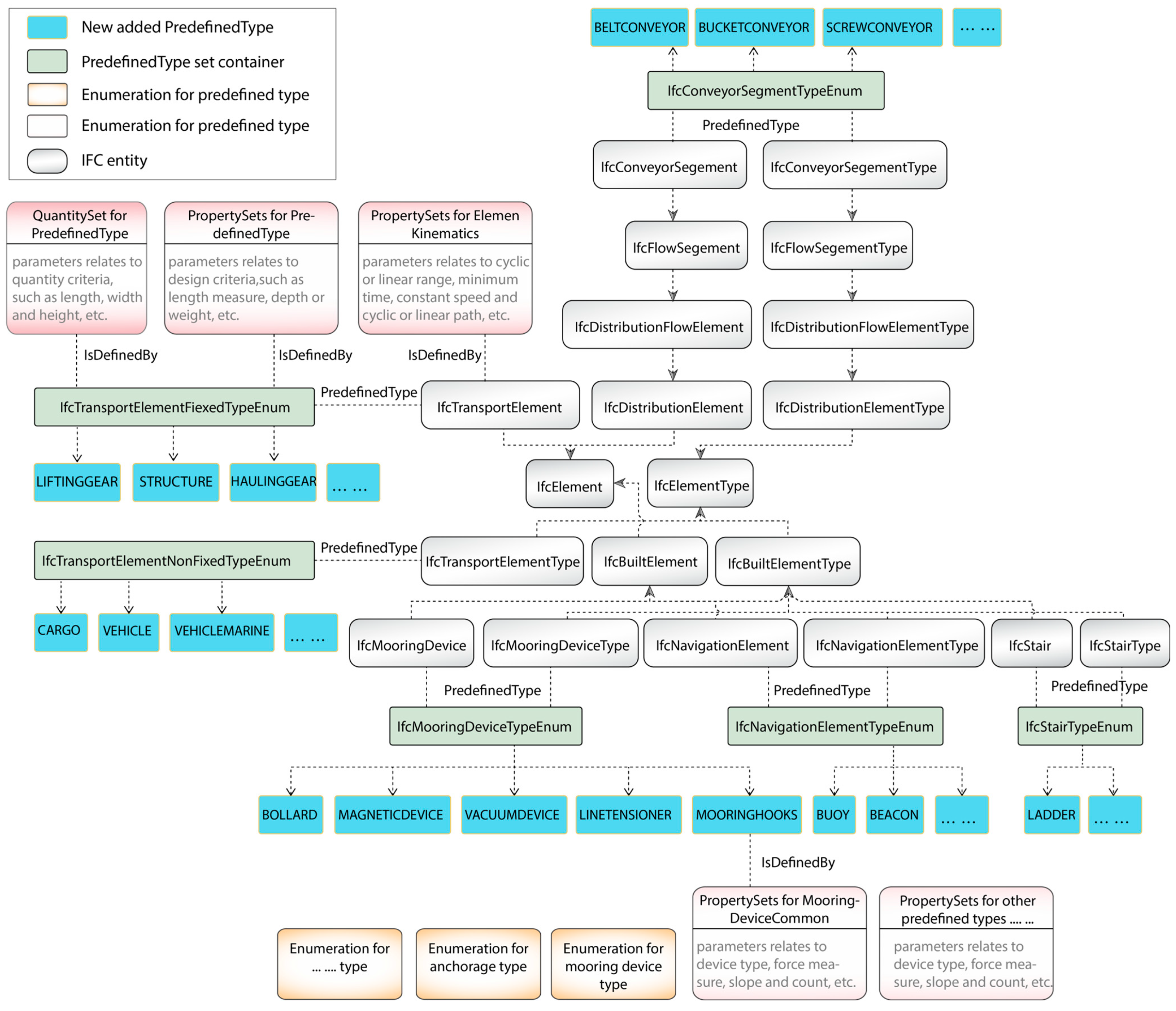
The berthing area model illustrates the application of IFC 4.3 to the design and operation of quay walls, piers, and terminal spaces. The entire facility is structured as an IfcFacility, subdivided into IfcFacilityPart entities representing structural and operational components. Each berth is modelled as an IfcSpace, enriched with attributes related to vessel type, mooring capacity, and service functionality. Operational zones—such as customs inspection areas, cargo handling regions, or hazard zones—are grouped using IfcZone. Mooring infrastructure, including bollards, fenders, ladders, buoys, and guidance systems, is modelled using IfcTransportElement, IfcMooringDevice, or IfcNavigationElement, depending on the function. These are semantically classified using predefined enumerations, such as IfcMooringDeviceTypeEnum or IfcTransportElementFixedTypeEnum.
Figure 8 presents the semantic classification structure for these supporting infrastructure elements, including mooring devices, ladders, conveyors, and marine transport elements. The diagram illustrates the classification of components such as bollards, buoys, ladders, conveyors, and mooring equipment, along with their predefined types (IfcTransportElementTypeEnum, IfcMooringDeviceTypeEnum, etc.) and related property sets.
4.5. Case Studies: Implementation and Validation
To validate the semantic modelling strategies and schema interpretations developed in the preceding sections, two pilot case studies were conducted in collaboration with national infrastructure agencies and engineering consultancies. These case studies demonstrate the practical applicability of the IFC schema in the context of real-world port and waterway infrastructure projects; by applying schema-based modelling workflows to representative use cases—a shipyard redevelopment and a ship lock design—the pilots assess the schema’s capacity to support openBIM principles, multidisciplinary coordination, and lifecycle-oriented information management. Both pilots were selected for their complexity, public relevance, and wide-ranging modelling requirements. The projects integrated planning, design, and environmental data, and were evaluated in terms of semantic completeness, schema compliance, and toolchain interoperability. The modelling was carried out using a combination of industry-standard BIM authoring tools, IFC validators, and custom data parsers, ensuring adherence to the data schema.
4.5.1. Case Study A: Shipyard Master Planning
The first pilot involved the redevelopment of a large coastal shipyard, led by the China Communications Construction Company (CCCC). The project included the reconfiguration of dry docks, logistics zones, and berthing infrastructure to accommodate expanded naval and commercial operations. The modelling objective was to support early-stage master planning, enabling the integration of regulatory constraints, environmental conditions, and functional zoning into a unified digital model. The facility was modelled using IfcMarineFacility and decomposed into parts using IfcFacilityPart to represent functional divisions, such as dry docks, pump stations, workshops, and access routes. Environmental features, including tidal flats, sediment zones, and coastal buffers, were modelled using IfcExternalSpatialElement and enriched with Pset_EnvironmentalCondition. Operational zones (e.g., fuelling stations, customs checkpoints, maintenance yards) were grouped using IfcZone.
The modelling followed a phased information delivery approach in line with the IDM-based workflows outlined in
Section 4.3. Initial inputs—such as GIS boundaries, bathymetric data, and topographic scans—were structured into IfcSite and IfcGeotechnicalElement. Subsequent phases introduced spatial hierarchies, functional zones, and volumetric representations.
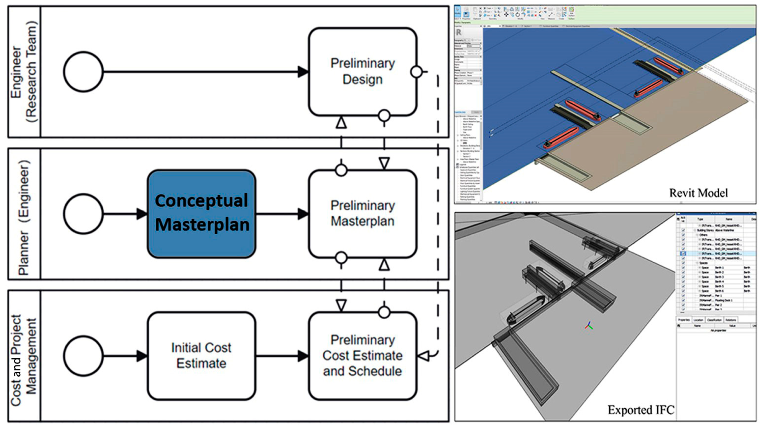
Figure 9 illustrates the Revit-based master planning model and its export as an IFC-compliant deliverable. The figure shows the conceptual masterplan (left), Revit-based 3d model (top right), and corresponding IFC export (bottom right), aligned with preliminary designs and cost estimation workflows.
Table 3 summarises the key entities and semantic structures used in this case.
4.5.2. Study B: Ship Lock Design Management
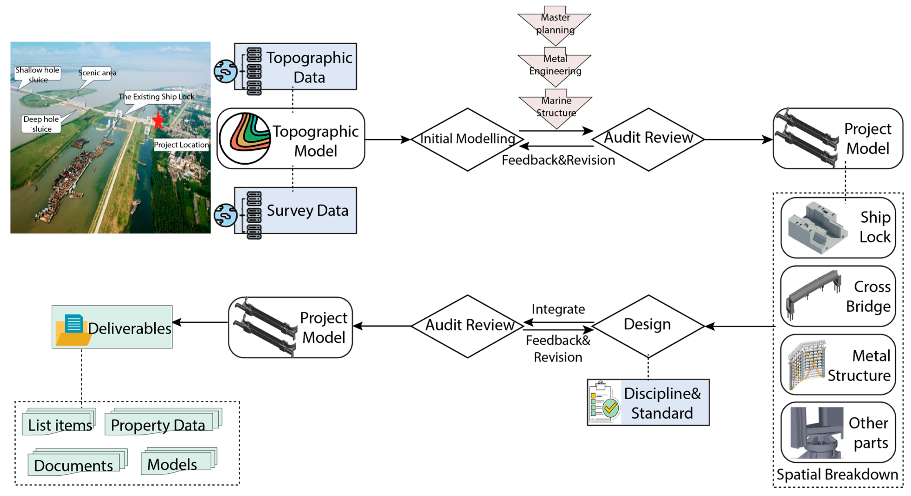
The second case study focused on a ship lock system, representing a multidisciplinary infrastructure project involving hydraulic engineering, transport structures, and architectural integration. The facility included a lock chamber, cross-lock bridge, adjoining roadways, and hydraulic regulation systems, requiring structured collaboration among specialists.
The design process began with Initial State Modelling, incorporating field-measured data such as topographic and geological models sourced from on-site surveys. These data formed the foundation for subsequent design tasks and were integrated into the overarching master plan. Metallurgical engineering workflows and macro-marine structural design initiatives further refined the master plan. Following this, a rigorous quality-checking process was conducted, resulting in the first revision of the federated project model. A spatial decomposition framework was employed to break down the ship lock facilities into constituent elements, facilitating the volumetric allocation of work tasks. Specialised personnel were assigned to discrete components of the design, ensuring efficient task division. The outputs from these spatial subdivisions were amalgamated into an integrated design model, which underwent quality assurance checks and formal approval processes. Deliverables such as models, documentation, and datasets were extracted from the revised model to serve subsequent project phases.
Figure 10 shows the logical flow of design activities across disciplines, culminating in a model export. The figure illustrates the modelling process, from topographic data and survey models to discipline-specific components (e.g., ship lock, bridge, metal structures) and the final IFC deliverables.
To manage the complexity, the team applied a layered spatial breakdown using IfcMarineFacility and IfcFacilityPart for components such as lock chambers, flow channels, and control zones. Infrastructure elements like the cross-lock bridge were modelled using IfcBridge, and roadways were modelled using IfcRoad. The lock gates were modelled as large-scale assemblies using IfcDoor, IfcElementAssembly, IfcPlate, IfcBearing, and IfcDiscreteAccessory, demonstrating the schema’s flexibility in adapting building-centric entities for infrastructure-scale components. Supporting systems (lighting, hydraulics, electrical) were modelled using IfcDistributionElement and grouped via IfcDistributionSystem.
Across both planning and design contexts, the schema supported the structuring of spatial hierarchies, the representation of physical components, and the integration of environmental data. The use of predefined entities and property sets enabled a consistent and interoperable modelling approach, while supporting compliance with domain-specific requirements. Moreover, the pilots demonstrated that openBIM-based workflows can be successfully implemented in maritime infrastructure projects using existing tools and platforms. The ability to structure and exchange data across disciplines and lifecycle phases points to the growing maturity of IFC 4.3 as a standard for infrastructure-level digital modelling. These findings are further discussed in
Section 5, which reflects on broader implications, limitations, and future directions for semantically rich infrastructure modelling.
5. Discussion
5.1. Semantic Adequacy and Domain Alignment
A key contribution of this study is the demonstration that the BIM data schema, in its current form, provides semantic coverage for representing spatial, functional, and environmental aspects of port and waterway infrastructure. The formal mapping of schema entities to domain-specific components—such as the alignment of IfcFacility, IfcFacilityPart, and IfcExternalSpatialElement with shipyards, lock systems, and surrounding environmental zones—confirms the schema’s capacity to support hierarchical decomposition and integrated modelling. Furthermore, the use of predefined property sets and classification enumerations (e.g., Pset_ShiplockDesignCriteria, IfcMarineFacilityTypeEnum) facilitates the encoding of operational, regulatory, and performance-related metadata in a consistent and machine-readable manner.
Unlike previous schema versions, IFC 4.3 introduces a more generalised and object-oriented approach to infrastructure modelling, particularly for linear, geographically distributed, or multi-system environments. This makes it well-suited to the port and waterway sector, where infrastructure spans both built and natural domains, often intersecting with regulatory boundaries and environmental systems. The ability to represent both constructed and natural spatial elements within a unified semantic framework represents a significant step forward. This capability also aligns with broader digital transformation goals, including the development of digital twins, integration with geospatial platforms, and the implementation of lifecycle asset management systems.
5.2. Implementation Challenges and Toolchain Limitations
While the semantic adequacy is well established through both conceptual modelling and case study validation, several implementation challenges were identified at the toolchain and workflow levels. First, support for infrastructure-specific entities and property sets varies across BIM authoring platforms. In some cases, domain elements, such as mooring devices, hydraulic systems, or sediment zones, had to be represented using generic constructs like IfcBuildingElementProxy or required the manual assignment of custom properties. This inconsistency increases the risk of semantic drift and hampers the reusability of models across platforms and disciplines.
Moreover, the creation and validation of multidisciplinary federated models remains a labour-intensive process. In both pilot projects, the absence of standardised libraries or maritime-specific IFC templates necessitated high levels of schema literacy and domain expertise. While the information exchange scenarios defined in this study (
Section 4.3) offer a structured foundation for data delivery, they require a significant coordination effort and are not yet fully supported by automation or template-driven workflows. This highlights the need for the further development of toolchains, training resources, and reference implementations to support the consistent application in maritime contexts.
Environmental data integration, while feasible using IfcExternalSpatialElement and associated property sets, also revealed limitations. Attributes such as tidal variation, sediment transport, and geotechnical conditions are critical to port planning and asset performance, yet they lack standardised IFC templates or predefined property structures. Although these gaps do not necessitate schema extensions per se, they point to a broader need for domain-specific documentation, libraries, and modelling guidelines to ensure consistent semantic interpretation across projects. In this regard, amendments or auxiliary extensions to the IFC documentation—not the core schema—may be beneficial to support modelling practices tailored to the unique requirements of the port and waterway sector.
5.3. Advancing openBIM in Infrastructure Delivery
Their application in the two pilot case studies illustrates the growing maturity of openBIM methodologies for infrastructure-level projects. Traditionally associated with vertical building domains, openBIM is now proving effective in supporting the spatial and functional demands of complex, multi-system environments, such as ports, shipyards, and navigation locks. In both cases, the use of the IFC data schema enabled structured lifecycle data management and improved discipline coordination.
This reinforces the argument for adopting openBIM not merely as a technical standard, but as a strategic methodology for infrastructure delivery. As public infrastructure agencies and asset owners increasingly prioritise data interoperability, regulatory compliance, and operational transparency, the role of open standards, such as IFCs, becomes critical. However, realising the full benefits of openBIM at scale will require continued collaboration between schema developers, software vendors, regulatory bodies, and academic institutions. Investments must be made not only in schema evolution, but also in supporting ecosystems—including validation tools, training materials, domain-specific guidance, and certification pathways.
These findings suggest that openBIM, when applied through IFCs, addresses several critical challenges in port and waterway infrastructure delivery. Chief among these is the fragmentation of data across disciplines, the lack of standard semantic structures for environmental and operational elements, and the limited lifecycle continuity between planning, design, and asset management. By offering a unified data schema capable of accommodating spatial, functional, and environmental parameters, the application demonstrably improves interoperability, coordination, and information retention across project phases.
5.4. Limitations and Future Research
While this study demonstrates the feasibility of applying the BIM data schema to maritime infrastructure, several limitations remain. The case studies presented focused primarily on early planning and design coordination phases, with minimal engagement in construction sequencing or facilities management. Future work should explore how IFC-based models can be integrated into construction-phase tools, Internet of Things (IoT) platforms, and asset monitoring systems to assess their long-term value in performance tracking, predictive maintenance, and digital twin integration.
Additionally, the conceptual models developed for this study were authored manually by domain experts, relying on schema familiarity and the interpretation of use case requirements. To improve scalability and adoption, there is a pressing need for the development of automated modelling tools, rule-based templates, and domain-specific object libraries that can guide users through semantically correct model creation. Research into the semantic interoperability between IFCs and other open data standards, such as CityGML, INSPIRE, or Waterml, also remains an open and promising area for exploration, particularly in the context of environmental and geospatial integration.
Finally, while the current research confirms that schema extensions are not required, it also acknowledges that enhanced documentation, property sets, and modelling guidance specific to the maritime domain would significantly facilitate adoption. These enhancements should be pursued collaboratively, ensuring that they do not compromise the core objective of maintaining interoperable, standard-compliant, and vendor-neutral models.
6. Conclusions
The port and waterway sector presents a unique set of challenges for digital modelling, spanning complex spatial hierarchies, multidisciplinary coordination, and environmental integration. While traditional BIM practices have made significant strides in vertical construction and general infrastructure, they often fall short in capturing the semantic and operational complexity of maritime infrastructure. This study has addressed these limitations by demonstrating that the IFC 4.3 schema, when properly interpreted and semantically aligned, can meet the modelling requirements of this domain without the need for schema extensions. Through a structured methodology—comprising a schema analysis, workflow definition, conceptual modelling, and real-world validation—this research developed a semantic alignment framework tailored to the port and waterway infrastructure domain. Rather than proposing new schema constructs, the study leveraged existing IFC entities, property sets, and classification systems to represent domain-specific components, such as shipyards, lock systems, berths, and environmental zones. Conceptual models were developed using UML notation to formalise spatial decomposition and functional relationships. These models were then validated through two pilot case studies: a master planning scenario for a coastal shipyard and a design coordination project for a ship lock complex.
The findings indicate that the IFC data schema provides a robust foundation for openBIM workflows in the maritime infrastructure sector. Key schema constructs—including IfcFacility, IfcFacilityPart, IfcExternalSpatialElement, and domain-specific enumerations—were applied to represent spatial structures, physical systems, and environmental conditions. The use of predefined property sets enabled the consistent documentation of performance requirements, regulatory constraints, and operational attributes. Information exchange scenarios, aligned with the IDM methodology, further demonstrated the viability of lifecycle data management across planning, design, and handover phases. At the same time, the study recognises that some refinements and domain-specific support materials may be necessary to fully operationalise this approach at scale. While the core data schema is sufficient, there is a need for enhanced documentation, reference templates, and toolchain support to improve consistency and reduce the implementation overheads. These enhancements should focus not on changing the schema itself but on clarifying its application in the context of complex, multidisciplinary domains, such as ports and waterways. What distinguishes this study from prior work is its focus on semantic reinterpretation, rather than schema extensions. Instead of introducing new classes, the proposed framework demonstrates how schema elements can be systematically realigned to represent maritime infrastructure in a standards-compliant and tool-compatible way. This approach not only ensures interoperability within the openBIM ecosystem but also lowers the barrier for adoption by leveraging widely supported constructs. The study thus provides a novel pathway for applying IFCs in complex infrastructure domains that have traditionally been underserved by conventional BIM practices.
Looking ahead, future research should explore the integration of IFC-based models with construction management systems, asset monitoring platforms, and digital twins. Semantic alignment with external standards, such as CityGML for geospatial data or INSPIRE for environmental datasets, also represents a promising area for extension. Furthermore, the development of intelligent authoring tools, rule-based modelling templates, and smart classification systems can enhance the accessibility and scalability of semantically rich infrastructure modelling. While this study focused on maritime infrastructure, the methodology and findings are broadly transferable. The semantic alignment approach outlined here can serve as a blueprint for applying IFCs to other under-represented infrastructure domains, such as flood control systems, hydropower plants, and coastal defences. As the infrastructure sector continues its digital transformation, schema-aligned modelling strategies that prioritise interoperability, semantic clarity, and lifecycle consistency will be critical to achieving resilient, data-driven infrastructure delivery.


