Article

Research on the Bending Behavior of Concrete Beams Reinforced with CFRP Sheets Bonded Using BMSC

1
College of Building Engineering, Xiamen City University, Xiamen 361008, China
2
School of Architectural and Civil Engineering, Harbin University of Science and Technology, Harbin 150080, China
*
Author to whom correspondence should be addressed.
Buildings 2025, 15(12), 1980; https://doi.org/10.3390/buildings15121980
Submission received: 20 May 2025 / Revised: 2 June 2025 / Accepted: 5 June 2025 / Published: 8 June 2025
(This article belongs to the Topic Green Construction Materials and Construction Innovation)

Abstract

To improve the construction performance of inorganic adhesives used for bonding fiber-reinforced polymer (FRP) sheets to reinforce concrete structures, make rational use of resources, and reduce carbon emissions, double-shear tests on the interface bonding performance between bonded FRP sheets and cement mortar test blocks, as well as four-point bending tests on bonded carbon fiber-reinforced polymers (CFRPs) to reinforce concrete beams, were conducted using basic magnesium sulfate cement (BMSC) as the adhesive. The influence laws of parameters, such as the type of FRP sheet and the number of FRP sheet bonding layers on the shear performance of the bonding interface between BMSC and cement mortar test blocks, were investigated, as well as the influence laws of the number of CFRP sheet bonding layers and the type of binder on the bending performance of CFRP sheet-reinforced beams. The test results show that the ultimate load of CFRP-reinforced beams bonded with BMSC as the binder increased by 17.4% to 44.4% compared with the unreinforced beams and simultaneously improved the flexural stiffness and crack-limiting ability of the reinforced beams. The failure of the reinforced beam begins with the separation of the CFRP sheet from the concrete at the middle and bottom of the beam span. When the CFRP sheet of the reinforced beam is one layer and two layers, the flexural bearing capacity reaches 91.4% and 96%, respectively, of the reinforced beam, with epoxy resin as the binder under the same conditions. With the increase in the number of CFRP layers, the flexural bearing capacity of the reinforced beam improves, but the increased flexural bearing capacity does not increase proportionally with the increase in the number of sheet layers. By introducing the influence coefficient of BMSC on the flexural bearing capacity (FBC) of reinforced beams, based on the test results, the formula for calculating the FBC of concrete beams, which are reinforced with CFRP sheets bonded by BMSC, was developed. After verification, the calculation formulas established in this paper have high accuracy and can provide theoretical references for similar engineering applications.

1. Introduction

Compared with new construction projects, reinforcement and renovation projects can save approximately 40% of funds, shorten the construction period by about 50%, and increase the speed of capital recovery by 3 to 4 times. With the continuous growth in the demand for the repair and reinforcement of building structures, fiber-reinforced polymers (FRPs) are extensively utilized in the realm of structural enhancement and renovation in buildings by virtue of their excellent mechanical properties, good durability, high temperature resistance, and ease of construction [1,2]. In contrast to the conventional method of reinforcing with external steel plates, the FRP strengthening technique offers notable benefits in terms of being lightweight, corrosion resistance, construction process, maintenance cost, etc. [3]. Among them, carbon fiber-reinforced polymer (CFRP) is the most widely used. This is because, compared with other types of FRPs, CFRP has higher tensile strength and elastic modulus, as well as excellent fatigue resistance, corrosion resistance, and creep resistance [4,5]. The anchoring of CFRP directly affects the reinforcement effect. The traditional method is to use U-shaped hoses, but new reinforcement methods are constantly emerging, such as wedge-shaped bonding anchoring systems [6] and mechanical anchoring [7], providing reliable guarantees for the application of this reinforcement technology. In addition, for structures that urgently need to be restored and reinforced due to catastrophic events such as earthquakes, adhering FRP sheets is regarded as one of the most effective reinforcement solutions. This is because traditional concrete structure repair methods, such as the section increase method, the outer steel coating method, and the concrete replacement method, to varying degrees, have problems such as low construction efficiency and poor durability. Through the investigation and research on the failure of reinforced concrete column structures observed in the 2023 Kahramanmaraş earthquake, Işık [8] concluded that column damage is the main cause of structural failure. The two main reasons for the damage are low concrete strength and insufficient transverse reinforcement, as they directly affect the shear resistance capacity of the column. In this regard, through the simulation analysis of the damaged columns after the earthquake, the researcher proposed that the wound FRP-reinforced RC components can achieve rapid repair and effectively improve the shear resistance capacity of the structure. And in line with the Sustainable Development Goals, it enhances the integrity of the structure and promotes the effective utilization of resources. Moreover, the pseudo-static test results of FRP-reinforced earthquake-damaged columns conducted by Eshghi et al. [9], Fukuyama et al. [10], Tsonost [11], etc., show that FRP materials can effectively repair the bearing capacity and displacement ductility of earthquake-damaged columns, and both are higher than those of the original columns. Yao [12] reinforced three-scaled bridge pier models damaged by seismic action with external FRP and conducted low-cycle reciprocating loading pseudo-static tests. The results show that the external FRP reinforcement can effectively improve the seismic performance of the damaged bridge piers. The ultimate displacement of the post-earthquake repair increased by 18.2% compared with the original columns without reinforcement, and the cumulative energy consumption increased by 35.3%. Therefore, the bonding of FRPs to reinforce concrete structures, especially in the research on the rapid repair of structures after disasters, has important engineering application value. At present, the FRP sheet reinforcement technology generally uses organic adhesives such as epoxy resin as binders, which have poor high-temperature resistance, acid and alkali corrosion resistance, and toughness. In high-temperature environments such as fires, the strength of the adhesive layer will be significantly affected, resulting in a sharp degradation in the interfacial bonding performance between FRP sheets and the substrate, seriously threatening the safety of the reinforced structure [13,14]. In this regard, researchers have attempted to use inorganic adhesives such as alkali slag cementitious materials (ASCMs), geopolymers, magnesium phosphate cement, and ultra-high toughness cement composite (UHTCC) instead of epoxy resin adhesives in FRP reinforcement projects [15,16,17]. Zheng et al. [18] used ASCM to affix CFRP sheets to strengthen concrete beams and conducted bending tests. The tensile reinforcement of the test beams had yielded, but some of the beams were damaged due to the CFRP being pulled off, and some of the beams were damaged due to the concrete being crushed. The calculation formulae for the stiffness and flexural bearing capacity (FBC) of beams reinforced with CFRP sheets bonded with ASCM were proposed. Wang [19] bonded UHTCC to concrete and investigated the bonding properties between UHTCC and concrete through tensile, shear, and flexural tests on bonded specimens. The results show that the interfacial bond strength is determined by the weak surface between the UHTCC material, the bonding layer, and the concrete, and it is effectively improved by the volcanic ash effect and microaggregate filling capacity of fly ash (FA) and silica fume (SF). Hou et al. [20] also found that reinforcing reinforced concrete columns with FRP web—UHTCC could effectively restrain core concrete and inhibit cracks and remarkably improve the ductility and energy dissipation capacity of the columns. Wu et al. [21] found, through tensile shear tests, double-shear tests, and bending tests of reinforced beams, that the breaking tensile force of epoxy resin double-shear specimens at 160 °C was only 21% of that of geopolymer double-shear specimens. And the reinforcing effect of CFRP sheets adhered by geopolymer and CFRP sheets adhered by epoxy resin adhesive on concrete beams is basically comparable at room temperature. Qi [22] conducted open-flame tests on concrete beams reinforced with carbon fiber cloth bonded to geopolymers, further verifying that geopolymers used as adhesives to bond CFRP sheets to reinforce beams still have good reinforcement effects in high-temperature environments. Zhang [23] modified magnesium phosphate cement (MPC) with wollastonite and studied its shear strength when used as an adhesive to bond CFRP sheets to reinforce concrete. It was found that the bonding performance of concrete double-shear specimens bonded with MPC and CFRP sheets after dry–wet cycling, soaking in tap water, and erosion by MgSO4 solution was all superior to that of specimens bonded with epoxy resin. Ren [24] reinforced concrete beams with CFRP sheets adhered with MPC. The results of the bending test showed that the FBC of the reinforced beams increased by 23.1%, and the deformation was significantly reduced. From the above analysis, it can be known that at present, the application of inorganic glue instead of organic glue in FRP sheet reinforcement projects has become a research hotspot. However, at present, inorganic adhesives have not been widely used. Part of the reason is that some inorganic adhesives, such as ASCM, often have large-particle substances as raw materials, which are prone to causing a poor wetting effect [25,26]. Some inorganic adhesives, such as MPC, have raw materials that are detrimental to the natural environment and are relatively expensive [27,28]. Basic magnesium sulfate cement (BMSC) is a novel type of material based on the preparation method of magnesium sulphate cement by adding appropriate additives [29,30]. Its hydration product is needle-rod 5·1·7 phases (5Mg(OH)2·MgSO4·7H2O), and it has stable performance [31]. The material has high strength, good durability, does not easily absorb moisture back into the brine, and has a better ability to protect the rebar against rust [32]. Moreover, the calcination temperature of magnesia cement is 300–400 °C lower than that of ordinary Portland cement, significantly reducing production energy consumption. It has been recognized as a “green engineering material of the 21st century” [33]. Promoting the application of BMSC in the field of civil engineering not only meets the demand for low-carbon transformation in the construction industry but also promotes the efficient utilization of magnesium resources, which is of great value for building a resource-conserving society and achieving the “dual carbon” goals in the construction industry [34]. Moreover, the main raw materials of BMSC (MgO and MgSO4) have particle sizes within 100 μm, which can be fully immersed into the interior of FRP sheets, making it suitable for reinforcement construction with multiple layers of FRP sheets adhered [35]. However, at present, the research on BMSC mostly focuses on the mechanical properties of the material itself, and the application research in the field of carbon fiber cloth reinforcement is not in-depth enough [36].
In this paper, BMSC was used instead of epoxy resin adhesive to bond CFRP sheets to reinforce concrete beams. The preferred mix ratio of BMSC was determined based on the physical and mechanical property tests. Double-shear tests were conducted on 10 cement mortar test blocks with FRP sheets adhered. Four-point bending tests were conducted on one unreinforced beam, one epoxy resin adhesive CFRP sheet-reinforced beam, and four BMSC adhesive CFRP sheet-reinforced beams. The flexural performance of concrete beams reinforced with BMSC adhered to CFRP sheets was investigated, and the calculation formula for the flexural bearing capacity of the normal section of beams reinforced with BMSC adhered to CFRP sheets was established. The BMSC raw material adopted in this paper has small particles, fast hardening, and early strength, is energy-saving and environmentally friendly, and has the abilities of self-strengthening and self-toughening. It can be used as an effective substitute for epoxy resin adhesive. The established calculation model of the bearing capacity of the reinforced beam takes into account the influence of BMSC as the binder on the flexural bearing capacity of the reinforced concrete beam with CFRP sheets adhered and further considers the problem that the increase in the number of CFRP sheet layers does not lead to a proportional increase in the flexural bearing capacity of the reinforced beam. And these two factors were transformed into BMSC influence coefficients and introduced into the calculation formula, thereby improving the calculation accuracy. The research results in this paper can provide a theoretical basis for the application and promotion of BMSC in the field of reinforcement.

2. Materials and Methods

2.1. Materials

2.1.1. BMSC

The main raw materials of BMSC are light-burned MgO and MgSO4·7H2O, with an appropriate amount of citric acid added as an admixture, and FA and SF as mineral admixtures. The specific mix ratio is as follows: the molar ratio of MgO:MgSO4:H2O is 9:1:20, the dosage of FA (fly ash) is 20%, the dosage of SF (silica fume) is 5%, and the dosage of citric acid is 1%. The raw materials are produced by the Nanfeng Chemical Group Co., Ltd., in Yuncheng, China. Under this mix ratio, the fluidity of the slurry is 145 mm, and the initial and final setting times are 341 min and 477 min, respectively. According to GB/T17671-2021 “Test Methods for Strength of Cement Mortar (IOS Method)” [37], the compressive strength of the 40 mm × 40 mm × 40 mm cubic test blocks and the flexural strength of the 40 mm × 40 mm × 160 mm prismatic test blocks of BMSC at various ages are measured and shown in Table 1.

2.1.2. Concrete

The concrete measured cubic compressive strength is 38.3 MPa, the axial compressive strength is 26.1 MPa, the axial tensile strength is 2.5 MPa, and the elastic modulus is 3.1 × 10⁴ MPa.

2.1.3. Cement Mortar

The mass ratio of each component for making cement mortar is water/cement/sand = 1:3:0.5. According to the specification GB/T 17671-2021, 40 mm × 40 mm × 160 mm cement mortar test blocks were made. The measured compressive strength and flexural strength were 33.9 MPa and 6.7 MPa, respectively.

2.1.4. Reinforcements

The types of reinforcing bars used in concrete beams and related parameters are shown in Table 2.

2.1.5. FRP Sheet

The main performance indicators of CFRP sheets and basalt fiber-reinforced polymer (BFRP) sheets used in the test are shown in Table 3. Among them, CFRP is produced by Zhino Decorative Materials Co., Ltd. in Shanghai, China, and BFRP is produced by Nongchaoer Composite Materials Technology Co., Ltd. in Yancheng, China.

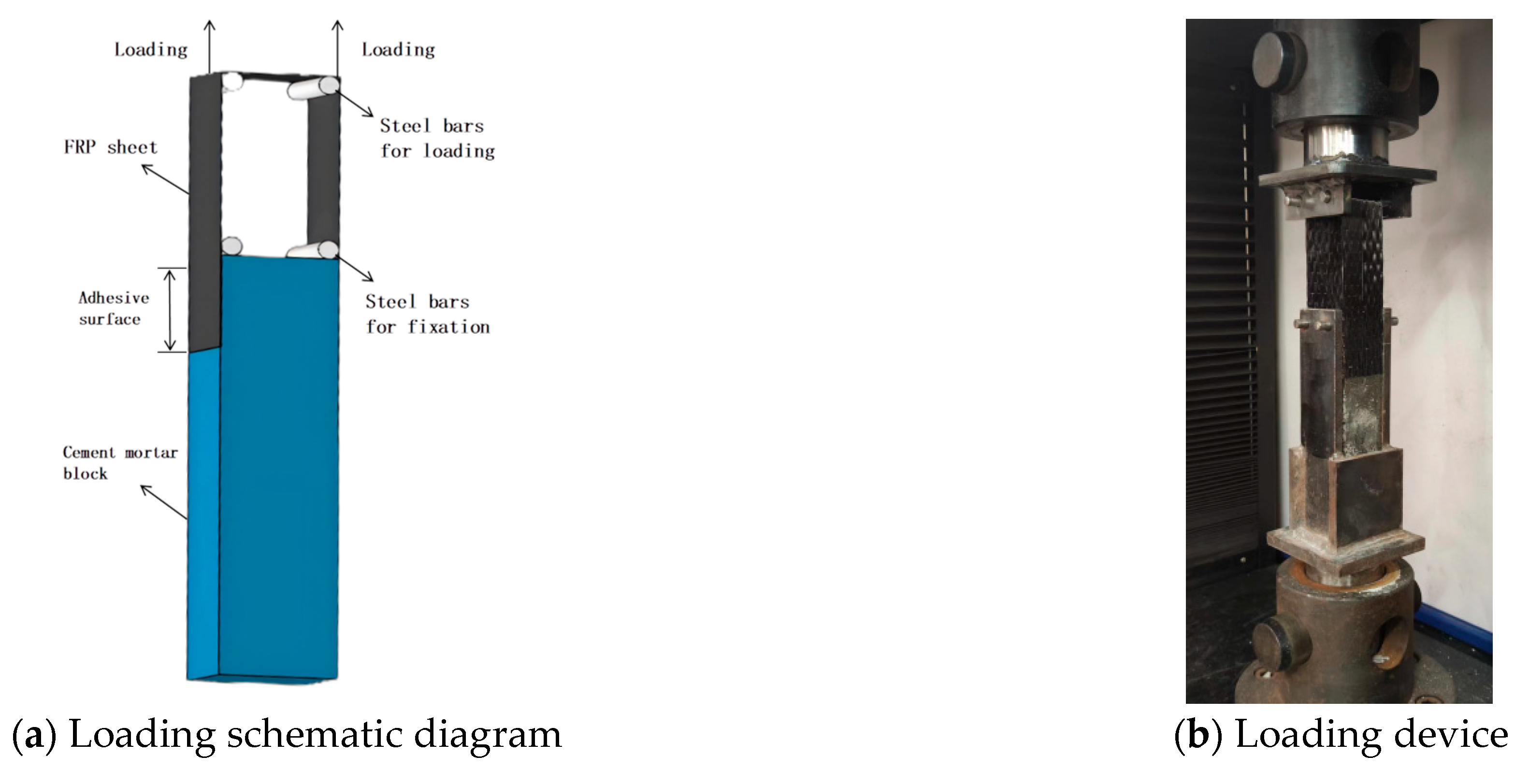
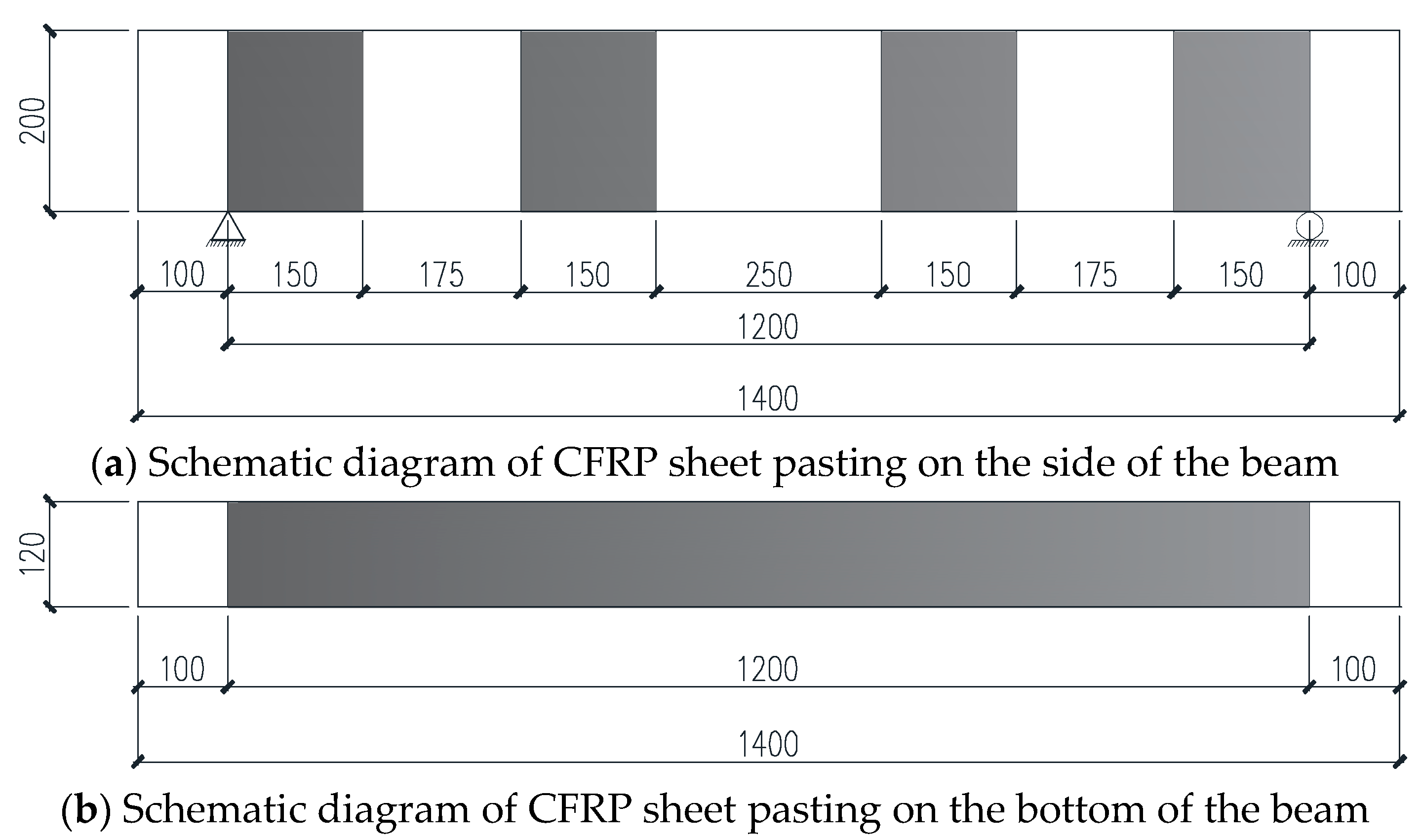
2.2. Double-Shear Test Method for Interfacial Bonding Performance

To study the bonding performance of BMSC adhering the FRP sheet, BMSC was used as an inorganic binder to adhere the FRP sheet, and the double-shear test of the bonding interface was carried out. The method of making the test piece is as follows: Firstly, make a 40 mm × 40 mm × 160 mm cement mortar test block. Then, grind and roughen the part where the FRP sheet is adhered at the end of the test block to increase the adhesion between the cement mortar test block and the adhesive layer. Cut the FRP sheet to a size of 400 mm × 40 mm, soak it in BMSC, and press the FRP sheet with a roller at the same time to allow the BMSC to seep into the interior of the FRP sheet. Apply a layer of approximately 2 mm thick base adhesive on the surface of the cement mortar test block. After waiting for 1–2 min, stick the 35 mm length area at one end of the FRP sheet downward onto the surface of the cement mortar test block and repeatedly squeeze out the internal air bubbles of the FRP sheet. Finally, apply a layer of approximately 2 mm thick surface adhesive on the surface of the FRP sheet as a protective layer. After the curing of the specimens is completed, the specimens are fixed on the WDW-200 microcomputer-controlled electronic universal material specimen machine with fixtures and loaded at a loading speed of 2 mm/min. The schematic diagram of the test loading is shown in Figure 1. The parameters of the double-shear test are shown in Table 4.

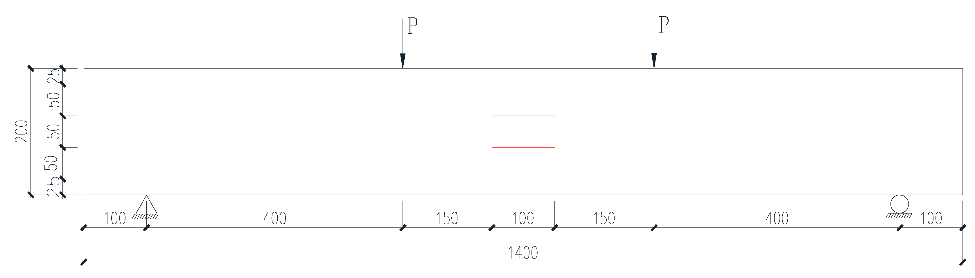
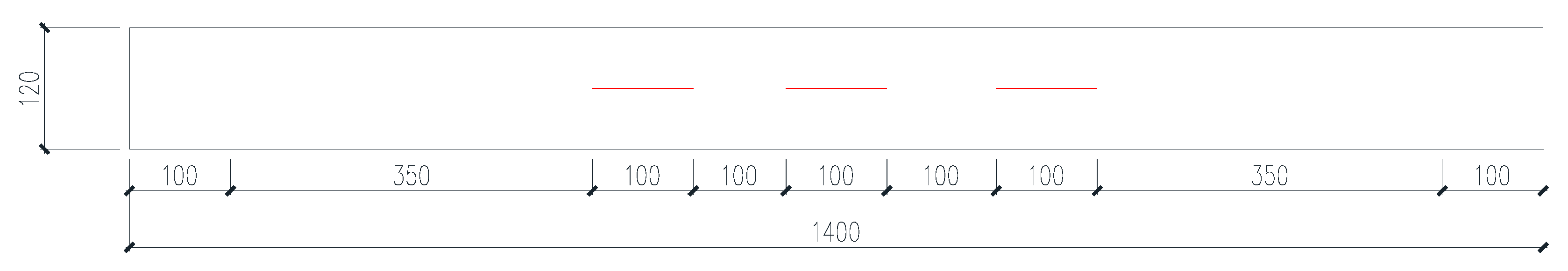
2.3. Bending Test Method for Concrete Beams Reinforced with FRP Sheets

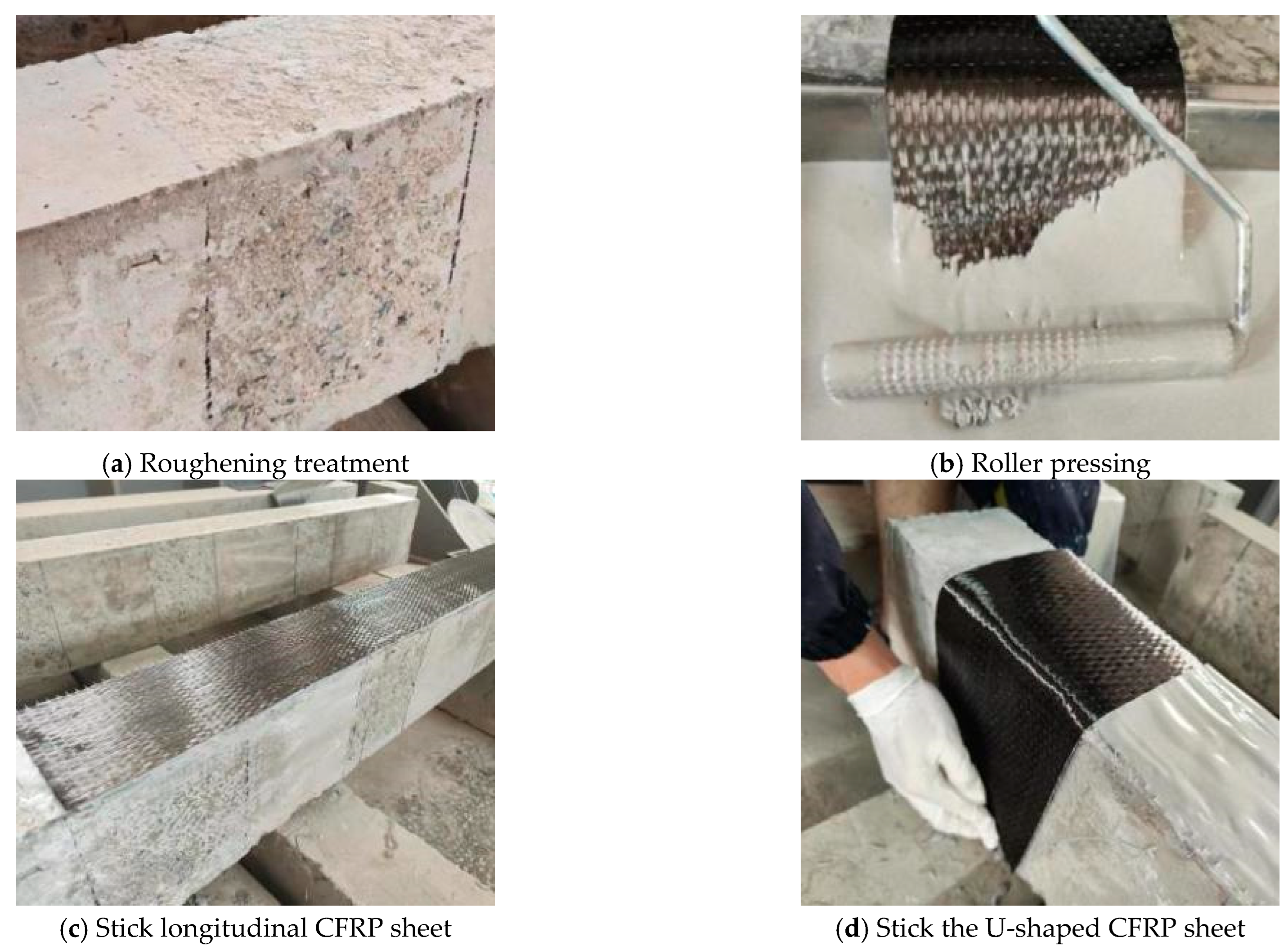
2.3.1. The Construction Process of Adhering FRP Sheets to the Test Beam

The construction process of reinforcing the test beam with FRP sheets is shown in Figure 2. The specific process is as follows:
(1)
According to the set FRP sheet bonding area, grind off the floating slurry on the surface of the beam, and use a chiseling hammer to roughen the corresponding positions on the surface of the test beam to increase the surface roughness of the beam body and enhance the adhesion between the BMSC and concrete. Then rinse thoroughly with clean water.
(2)
Pour the prepared BMSC into the container, spread the cut CFRP sheet flat, immerse it in the BMSC, and repeatedly roll the CFRP sheet with a roller to ensure that the BMCS is fully impregnated into the interior of the CFRP sheet before bonding.
(3)
First, apply a layer of BMSC as a base adhesive in the treated CFRP sheet bonding area to prevent the dry concrete surface from absorbing moisture from the BMSC and affecting the bonding performance. The soaked FRP sheet is then attached to the surface of the test beam, and a roller is repeatedly rolled on the surface of the CFRP sheet to ensure that the CFRP sheets are fully bonded to the surface concrete of the test beam. U-shaped hoops are stuck to the corresponding positions on the side of the test beam, and finally a layer of BMSC surface adhesive is applied on the surface of the CFRP sheet as a protective layer.
(4)
After the BMSC surface adhesive has initially set, cover the CFRP sheet surface with plastic film and water it for curing at room temperature to keep the beam moist. After 14 days, conduct the bending test on the test beam.

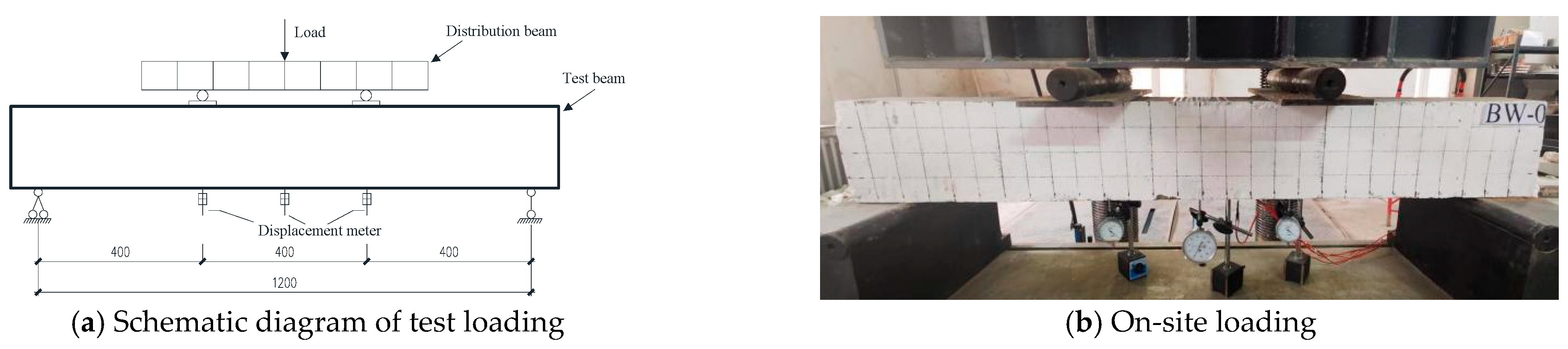
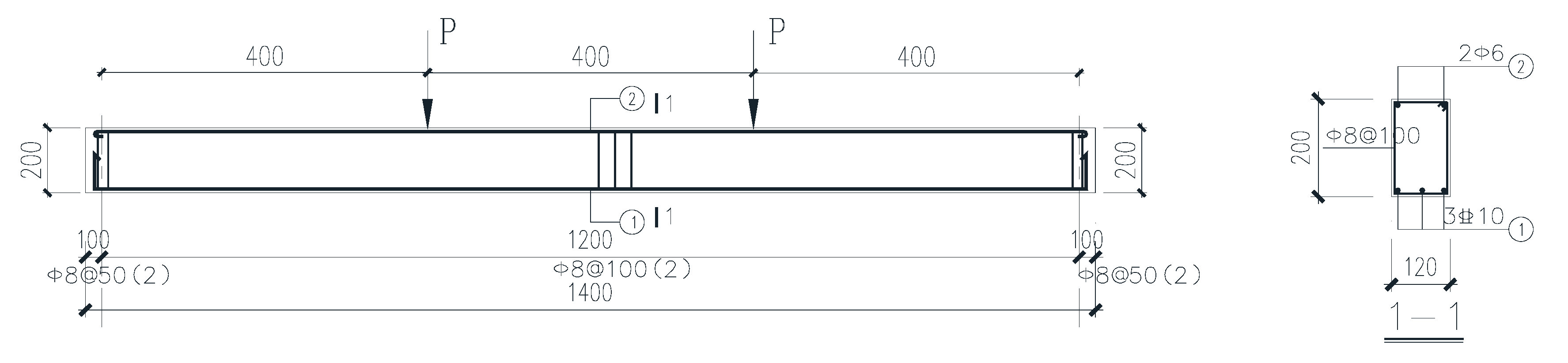
2.3.2. Test Beam Loading Method

The test loading situation is shown in Figure 3. The test method in reference [38] adopts the four-point bending loading mode. This method can generate equal bending moments in the two loading point areas without shear force, thus enabling the bending performance of the reinforced beam to be examined over a large range. Before the formal loading, preload 10 kN, and check whether the contact of each part of the loading device and the readings of the test instrument are normal. After confirming that there are no errors, unload and proceed with the formal loading 5 to 10 min later.

2.4. Test Beam Parameters

The relevant parameters of the unreinforced beam are shown in Figure 4 and Table 5. The beam span is L = 1400 mm, the calculated span is L0 = 1200 mm, the thickness of the concrete protective layer is 25 mm, and the cross-sectional dimensions are b × h = 120 mm × 200 mm.

2.5. The Position for Pasting the CFRP Sheet

The pasting position of the CFRP sheet is shown in Figure 5. A CFRP sheet with a width of 120 mm was pasted within the clear span range of 1200 mm at the bottom of the test beam. And U-shaped CFRP sheets were attached near the fabrication of the test beams and at 1/3 of the clear span to improve the anchorage to the bottom sheet.

2.6. Test Data Collection

2.6.1. Concrete Strain

Strain gauges were uniformly attached at the L/2 of the test beam along the height of the section to measure the strain distribution in the concrete, as shown in Figure 6 (the red area represents the collection point position).

2.6.2. Beam Deflection

One displacement meter is arranged at the L/2 of the test beam, and one displacement meter is, respectively, arranged at the left and right support sections to measure the support displacements. The deflection of the beam is taken as the difference between the mid-span displacement of the beam and the displacement of the support.

2.6.3. CFRP Sheet Strain

Strain gauges are arranged at the mid-span position at the bottom of the beam and at the left and right loading points, respectively, to measure the strain of the CFRP sheet, as shown in Figure 7 (the red area represents the collection point position).

2.6.4. Observation of Cracks

During the loading process, mark the location and development of the cracks, and use the crack observation instrument to observe and record the crack widths.

3. Results and Discussions

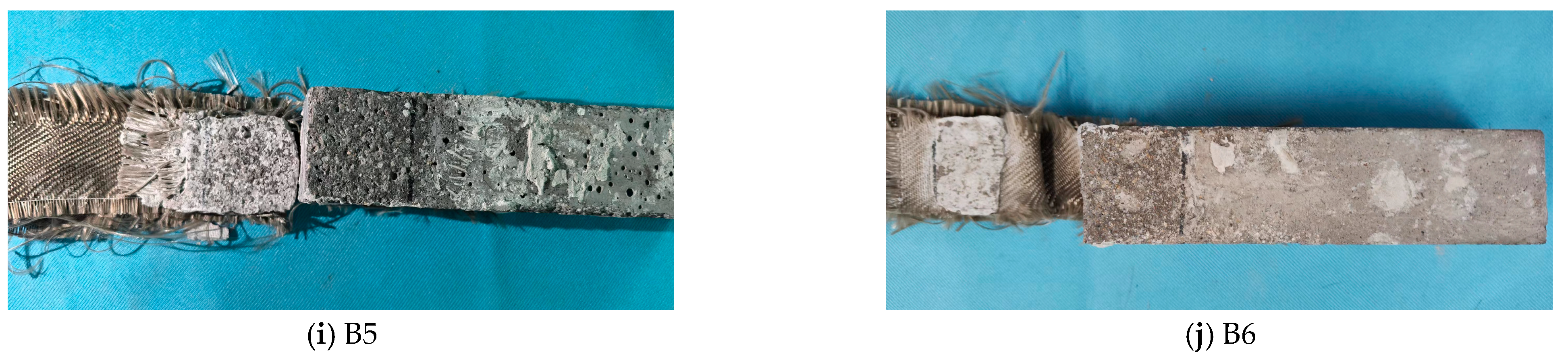
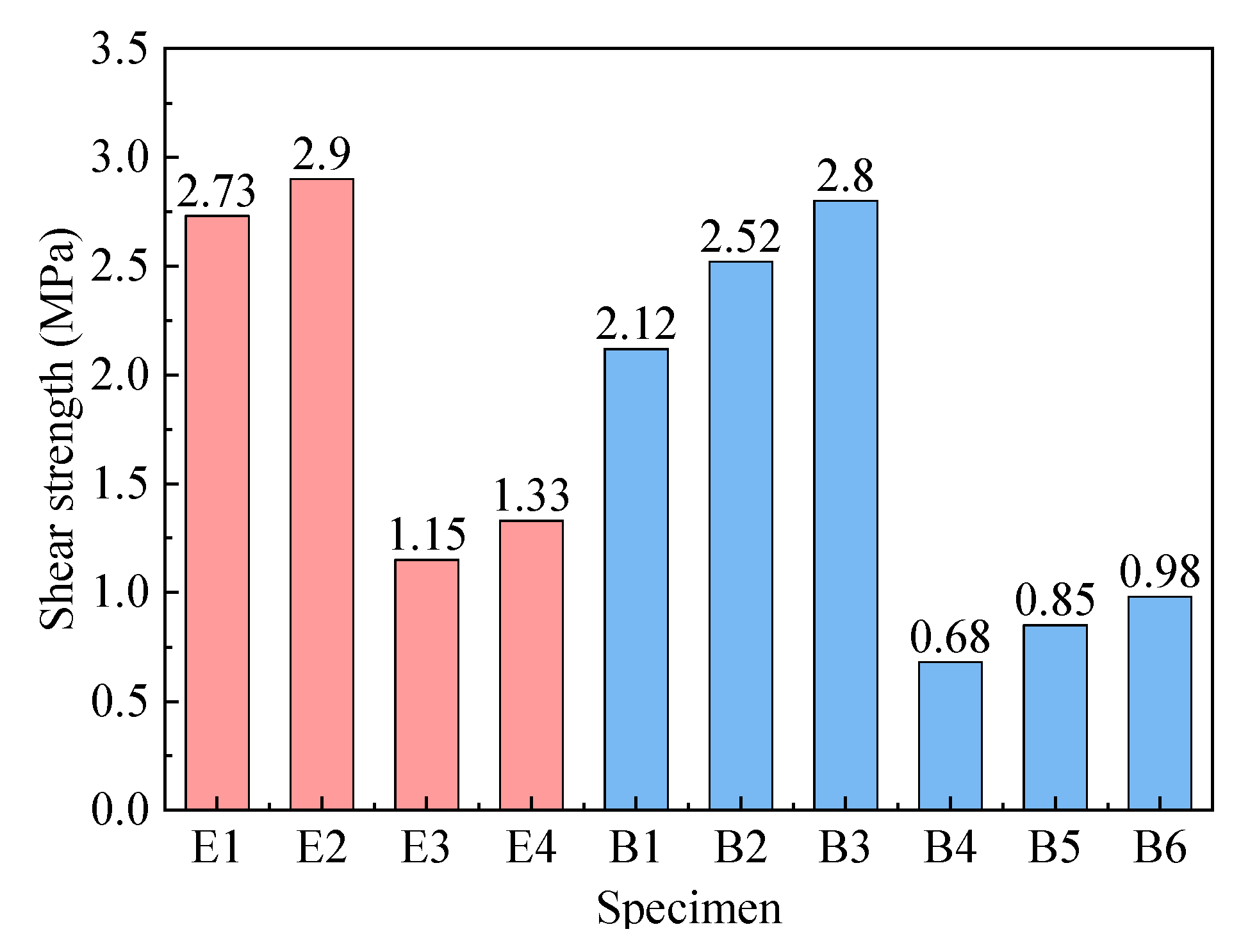
3.1. Double-Shear Test Results of CFRP Adhered with BMSC

The failure phenomenon of the double-shear specimen is shown in Figure 8. It can be seen from Figure 8a–d that the double-shear test failure mode of the CFRP and BFRP sheets bonded with epoxy resin is the bonding failure at the interface between the adhesive layer and the cement mortar; that is, the FRP sheet and the adhesive layer of the adhesive are completely detached from the bonding area, and the cement mortar in some areas is torn and removed by the FRP sheet. It is indicated that the epoxy resin adhesive has a good bonding effect on both types of sheets. It can be seen from Figure 8e–g that when BMSC is used to bond CFRP sheets, the failure mode is that the interface between the CFRP sheet and the BMSC adhesive layer is separated, while some carbon fiber filaments still remain on the surface of the cement mortar test block. With the increase in the number of CFRP sheet bonding layers, some areas of the cement mortar surface layer are torn off by the CFRP sheet, which is similar to the failure mode of the CFRP sheet specimens bonded with epoxy resin, showing good bonding performance. It can be seen from Figure 8h–j that when BMSC is adhered to BFRP sheets, the failure mode of the double-shear test of the specimens is that the BFRP sheets and the adhesive layer of the binder are torn off as a whole from the bonding surface of the cement mortar test block, resulting in a significant decrease in the shear strength. During the loading process of the specimen, the BFRP sheet continuously produced the phenomenon of filament drawing, and some fiber filaments broke, which was related to its weaving method. When cutting BFRP sheets, the transverse fiber filaments of the cross-section are damaged, making the originally closely arranged longitudinal fiber filaments relatively loose, thereby affecting their integrity. The double-shear test results of each specimen are shown in Figure 9. As can be seen from Figure 9, under the same number of bonding layers, the interfacial shear strength of the BMSC-adhered CFRP sheet and cement mortar test block is slightly lower than that of the epoxy resin-bonded test block. When one layer is used, it reaches 77.6% of the epoxy resin-bonded test block, and when two layers are used, it reaches 86.9% of the epoxy resin-bonded test block. Moreover, the interfacial shear strength of BMSC when three layers of CFRP sheets are adhered is 1.11 times that when two layers are adhered, showing a better bonding effect on CFRP sheets. However, the interfacial shear strengths of BFRP sheets adhered with epoxy resin adhesive and BMSC and cement mortar test blocks are relatively low. This is because during the specimen fabrication, it was found that a filament drawing phenomenon occurred when shearing BFRP sheets, and this phenomenon was more obvious during the loading process. As a result, the fiber filaments were subjected to uneven force, thereby reducing the effective force-bearing area at the bonding interface. Based on the above analysis, this paper selects CFRP sheets for the flexural reinforcement test of concrete beams.

3.2. Bending Test Results

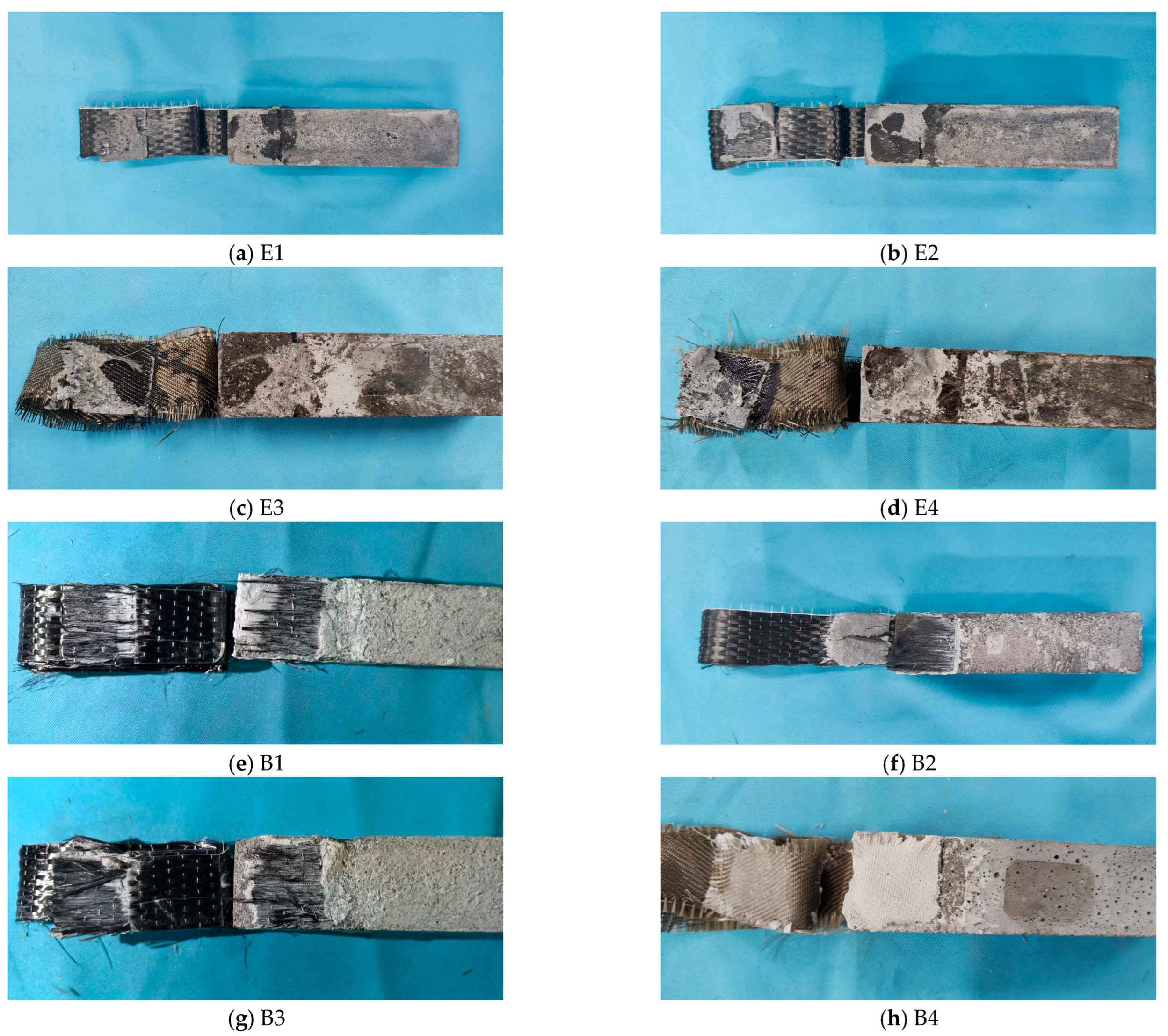
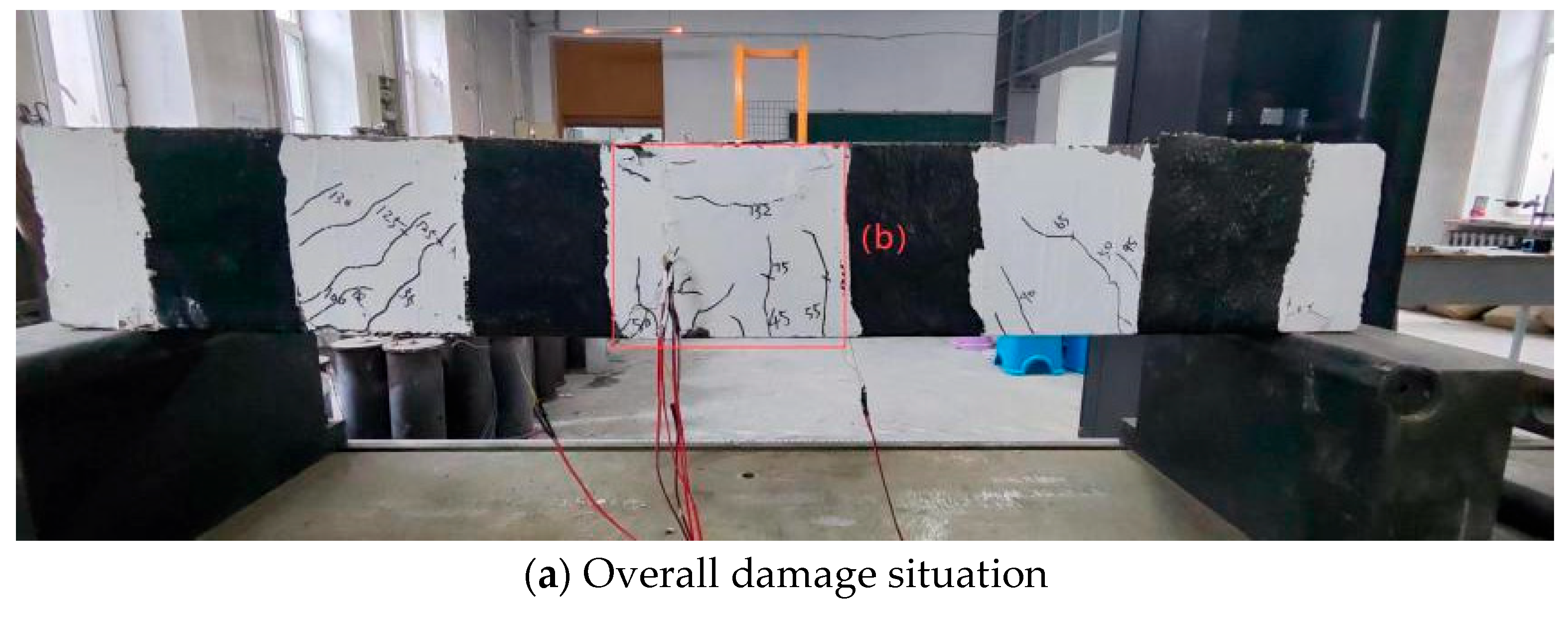
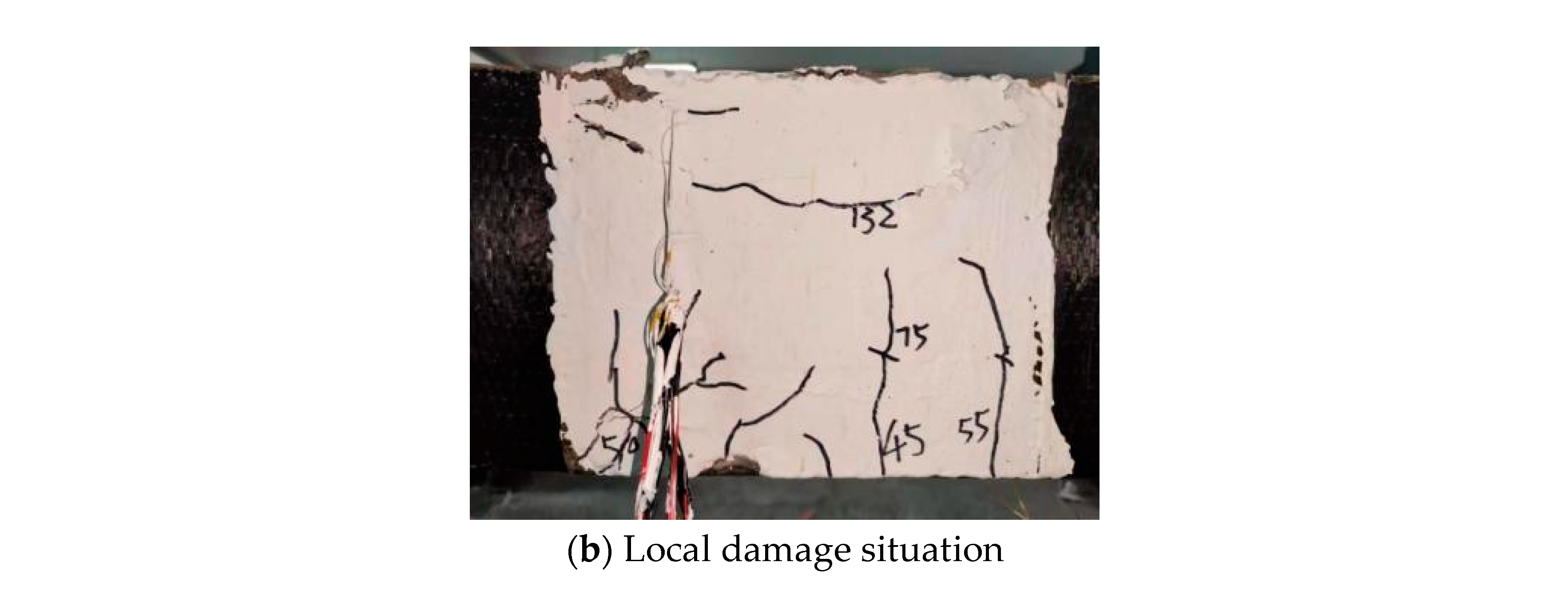
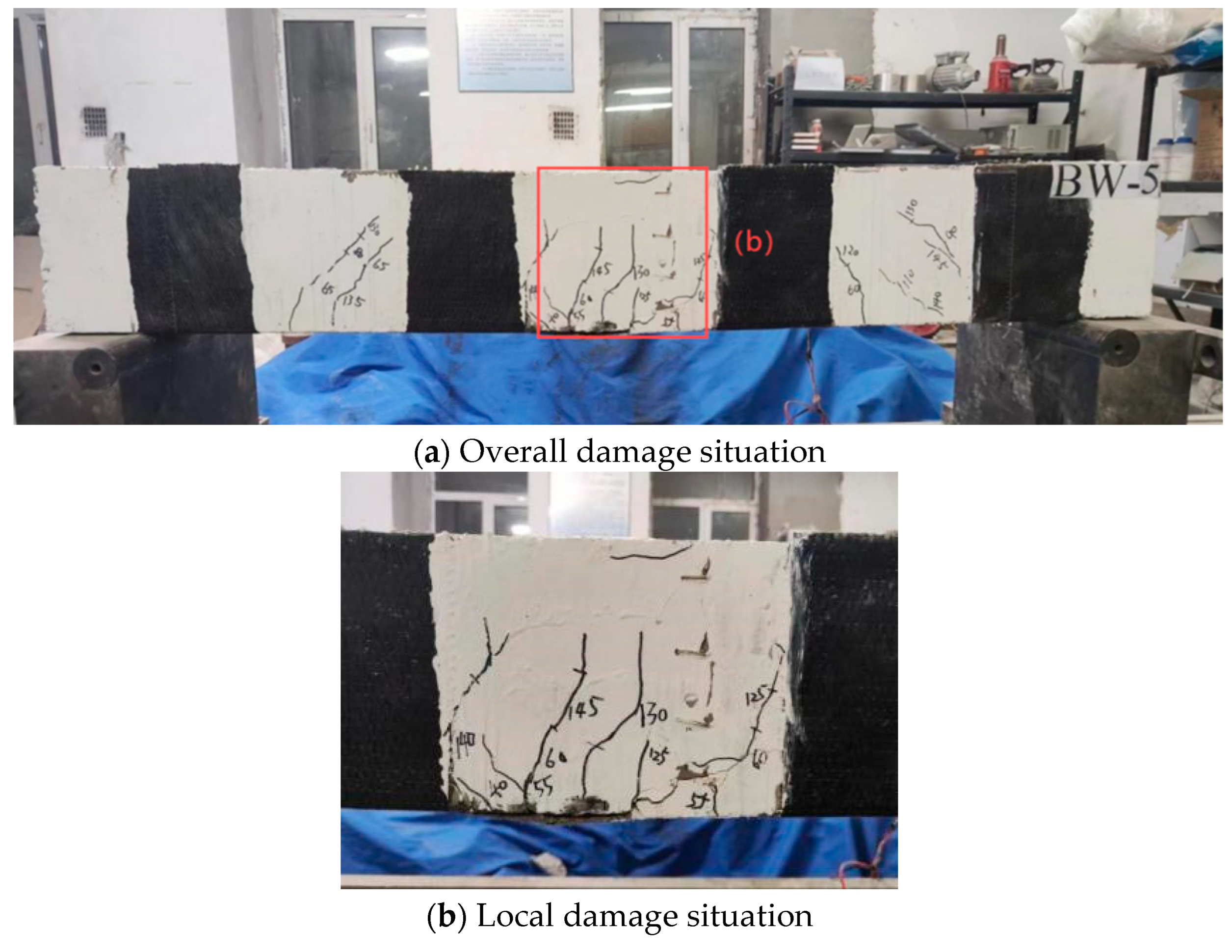
3.2.1. Experimental Phenomena
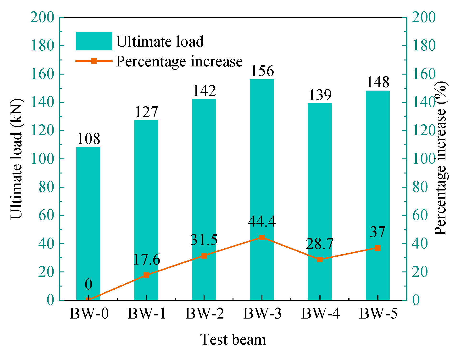
Beam BW-0 (unreinforced beam): The deflection of the beam varies little before the crack occurs, and the stress–strain relationship develops linearly. When loaded to 40 kN, vertical cracks first appeared near the loading point of the beam with a width of 0.04 mm. The original cracks then proceeded slowly in the vertical direction, and new vertical cracks continued to be created in the region between the two loading points. At a load of 50 kN, vertical cracks emerged at the lower boundary of the shear span region on the beam’s right side. It then gradually extended obliquely towards the loading point, with a width of 0.1 mm. When loaded to 90 kN, the variation range of mid-span deflection increased significantly. When the load was applied to 100 kN, horizontal cracks appeared in the mid-span compression zone of the test beam, and then the width of the horizontal cracks gradually increased. When loaded to 108 kN, the concrete in the compression zone at the mid-span position of the beam gradually peeled off, and then the concrete in the compression zone was crushed. The failure situation of the beam is shown in Figure 10.
Beam BW-1 (BMSC with one layer of CFRP sheets adhered to reinforce the beam): The deflection of the beam varies little before the crack appears, and the stress–strain relationship develops linearly. When loaded to 45 kN, one vertical crack appeared at each of the mid-span positions on the front and back of the beam, with a width of approximately 0.03 mm, and then it gradually developed. At a load of 55 kN, vertical cracks emerged at the lower boundary of the shear span region on the beam’s right side, and then gradually spread obliquely towards the loading point, with a width of 0.06 mm. When the load reached 105 kN, the deflection change in the beam increased significantly, and the development speed of vertical cracks also accelerated. Horizontal cracks emerged at the upper part of the beam when it was loaded to 115 kN. When the load reached 127 kN, the concrete at the bonding point between the mid-span bottom and the CFRP sheet cracked. The FBC began to decline, and then some of the concrete peeled off, and the concrete underwent crushing. Figure 11 illustrates the failure condition of the test beam.
Beam BW-2 (BMSC with two layers of CFRP sheets adhered to reinforce the beam): The deflection of the beam varies little before the crack appears, and the stress–strain relationship develops linearly. When loaded to 40 kN, vertical micro-cracks emerged at the mid-span position, with a width of approximately 0.02 mm. After that, the cracks developed slowly along the vertical direction, and gradually, new vertical cracks emerged. At a load of 55 kN, vertical cracks emerged at the lower boundary of the shear span region on the beam’s left side and then gradually extended towards the loading point, with a width of approximately 0.08 mm. When loaded to 115 kN, the variation range of mid-span deflection increased significantly. When loaded to 135 kN, the vertical crack development speed of the pure bend section increased, and the crack extension reached two-thirds of the cross-sectional height. When loaded to 148 kN, the concrete at the bonding area between the mid-span bottom and the CFRP sheet cracked, and the FBC began to decline. Subsequently, the concrete protective layer in some areas peeled off, and the concrete underwent crushing. Figure 12 illustrates the failure condition of the test beam.
Beam BW-3 (BMSC with three layers of CFRP sheets adhered to reinforce the beam): The deflection of the beam varies little before the crack appears, and the stress–strain relationship develops linearly. When loaded to 40 kN, vertical cracks emerged near the loading point, with a width of 0.03 mm. Then the original cracks gradually spread vertically, and new cracks occurred in the pure curved sections. When the load was applied to 60 kN, cracks appeared at the lower edge of the right shear span zone of the beam, and then gradually spread diagonally towards the loading point, with a width of approximately 0.08 mm. When loaded to 130 kN, the variation range of mid-span deflection increased significantly. When loaded to 150 kN, the vertical crack at the mid-span position extended to two-thirds of the cross-sectional height. When loaded to 156 kN, the concrete at the bottom of the mid-span of the test beam, where the CFRP sheet was adhered, cracked, and the FBC began to decline. Subsequently, the concrete protective layer in some areas peeled off, and at the top of the beam, the concrete underwent crushing. Figure 13 illustrates the failure condition of the test beam.
Beam BW-4 (epoxy resin adhesive adhered with one layer of CFRP sheets): The deflection of the beam varies little before the crack appears, and the stress–strain relationship develops linearly. When loaded to 45 kN, one vertical crack appeared at each of the mid-span positions on each side of the test beam, with a width of approximately 0.04 mm. Then the original cracks developed slowly along the vertical direction and new vertical cracks occurred in the pure curved sections. When the load was 55 kN, oblique cracks occurred at the lower edge of the left shear span zone of the beam. Then the cracks gradually developed obliquely towards the loading point, with a width of approximately 0.1 mm. When loaded to 100 kN, the variation range of mid-span deflection increased significantly. When loaded to 130 kN, horizontal cracks occurred in the mid-span of the beam, and then the width of the horizontal cracks gradually increased. When loaded to 138 kN, the concrete gradually peeled off, and then the concrete underwent crushing. Figure 14 illustrates the failure condition of the beam.
Beam BW-5 (epoxy resin adhesive adhered with two layers of CFRP sheets): The deflection of the beam varies little before the crack appears and the stress–strain relationship develops linearly. When loaded to 40 kN, vertical micro-cracks occurred at the mid-span position of the beam, with a width of 0.03 mm. Then the original cracks gradually spread upwards, and new vertical cracks gradually appeared in the pure bend section and spread. At a load of 60 kN, vertical cracks emerged at the lower boundary of the shear span region of the beam. Then the cracks gradually extended diagonally towards the loading point, with a width of approximately 0.1 mm. When loaded to 120 kN, the variation range of mid-span deflection increased significantly, and the vertical crack extension velocity of the pure bend section also increased. When loaded to 130 kN, the vertical crack at the mid-span position extended to two-thirds of the cross-sectional height. When loaded to 148 kN, the concrete at the bottom, where the CFRP sheet was adhered, cracked, and the FBC began to decline. Subsequently, the concrete protective layer in some areas peeled off, and the concrete underwent crushing. Figure 15 illustrates the failure condition of the test beam.
Comprehensive analysis: Compared to beam BW-0, the development of cracks in the CFRP sheet-reinforced beams occurred at a slower rate, with a reduction in both their number and width. It is indicated that CFRP sheets provide better crack inhibition for concrete beams. Except for the test beam BW-4, the failure forms of the remaining reinforced beams are basically similar. They are manifested as the cracking of the concrete at the bottom of the beam where the CFRP sheet is adhered, followed by the peeling off of the concrete protective layer in some areas and the crushing of the concrete at the top of the beam. It shows that BMSC inorganic adhesive has good bonding performance to CFRP sheets and concrete, which meets the requirements of engineering applications.

3.2.2. FBC Analysis

The ultimate load of the test beam is shown in Figure 16. It can be known from Figure 16 that compared with the unreinforced beam BW-0, the ultimate load of the reinforced beam increased by 19 kN, 34 kN, 50 kN, 31 kN, and 40 kN, respectively, from BW-1 to BW-5, with increases ranging from 17.6% to 44.4%. Among them, the maximum ultimate load of the reinforced beam with three layers of CFRP sheets adhered by BMSC is 156 kN, and its improvement effect is 44.4%. It is indicated that BMSC-adhered CFRP sheets have a better moment strengthening effect on concrete beams.
The adhesive plays a crucial role in fixing CFRP sheets and transmitting internal forces. Therefore, the quality of the adhesive is of great significance to the reinforcement effect of CFRP. The reinforcement effects of bonding CFRP with BMSC as the binder and epoxy resin as the binder on concrete beams were compared. When the number of CFRP sheet layers was one, the ultimate load of the beam reinforced with BMSC was 127 kN, reaching 91.4% of that of the beam reinforced with epoxy resin adhesive. When the number of CFRP sheet layers was two, the ultimate load of the BMSC reinforced beam was 142 kN, reaching 96% of that of the epoxy resin adhesive-reinforced beam. With the increase in the number of layers of CFRP sheets, the reinforcement effect of using BMSC as the binder gradually approached that of epoxy resin. Since epoxy resin has no particles and can fully impregnate CFRP sheets, the force on CFRP sheets is more uniform under loading conditions. The fine particles of inorganic adhesive may cause local voids after the adhesive infiltrates the CFRP sheet, and the initial cracks caused by the dry shrinkage of inorganic adhesive should not be ignored either. Therefore, under the loading state, a stress field may be generated inside the inorganic adhesive, which leads to a decrease in the uniformity of the force on the CFRP sheet. Thus, the bonding and reinforcement effect of epoxy resin adhesive is slightly better than that of inorganic adhesive. However, the BMSC adopted in this paper only has tiny particles, which have almost no effect on the wetting effect. Moreover, due to the presence of whisker hydration products, its own tensile strength and toughness are enhanced, and dry shrinkage cracks can be effectively suppressed. Therefore, the reinforcement effect of BMSC adhered to CFRP on the flexural performance of concrete beams is basically equivalent to that of epoxy resin adhesive.
From the analysis of the number of CFRP sheet reinforcement layers, when epoxy resin was used as the binder, the ultimate load of the reinforced beam when two layers of CFRP sheets were adhered increased from 139 kN to 148 kN compared with that when one layer of CFRP sheets was adhered, an increase of approximately 6.5%. When BMSC was used as an adhesive, the ultimate load of the reinforced beam when two layers of CFRP sheets were adhered increased from 127 kN to 142 kN compared with that when one layer of CFRP sheets was adhered, an increase of approximately 11.8%. When three layers of CFRP sheets were adhered, the ultimate load of the reinforced beam increased from 142 kN to 156 kN compared with that when two layers of CFRP sheets were adhered, increasing by approximately 9.8% again. It is indicated that when BMSC is pasted with multiple layers of CFRP sheets to reinforce concrete beams, the integrity between each layer of CFRP sheets is good, and the bonding effect with the surface of the concrete beam is good, thereby solving the problem that it is difficult to ensure the quality when pasting multiple layers of CFRP sheets with some inorganic cementitious materials with larger particles.

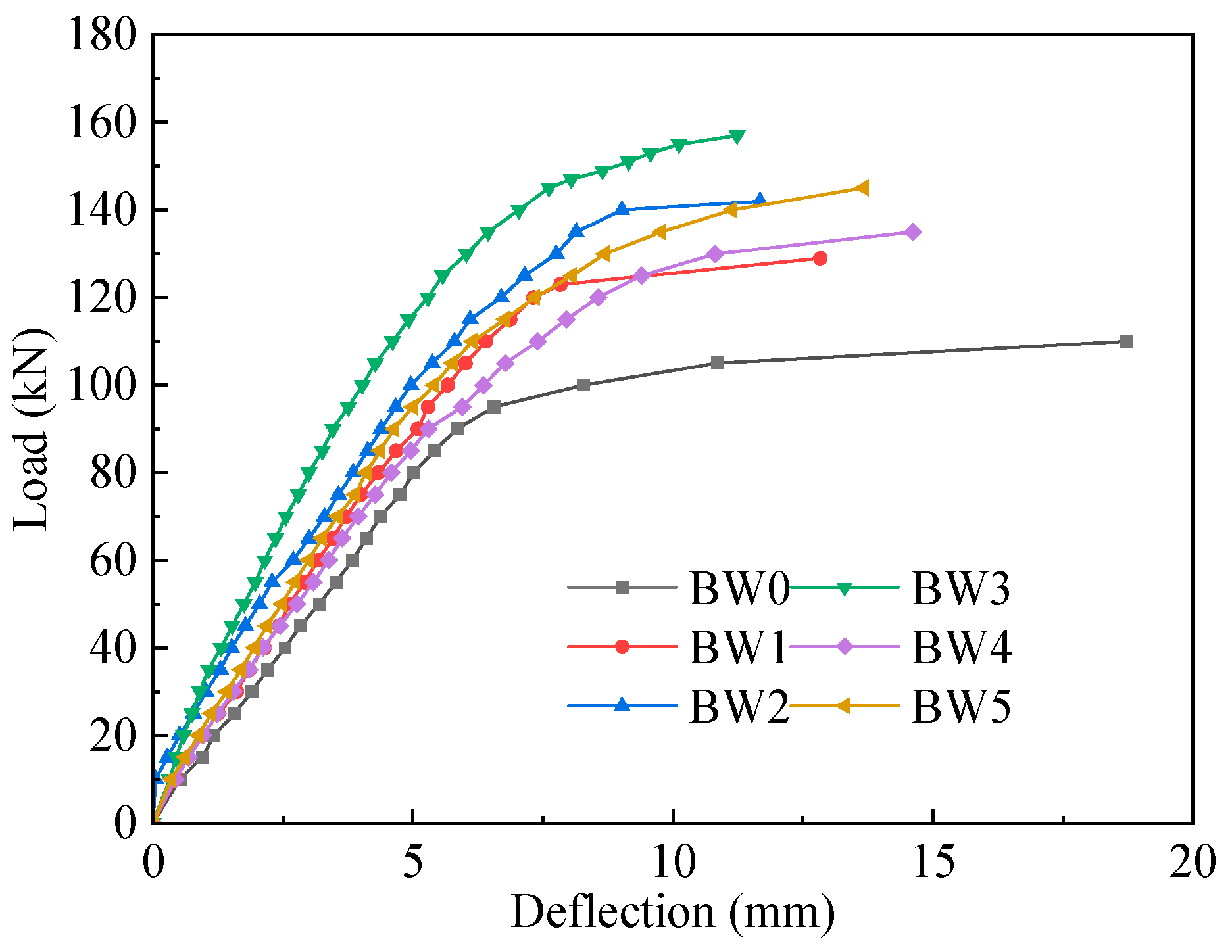
3.2.3. Deflection Analysis

The load–deflection curve of the test beam is presented in Figure 17. It is evident from Figure 16 that at the initial stage of loading, the development trends of the load–deflection curves of each test beam are almost the same. Compared with the unreinforced beam BW-0, the gradient of the load–deflection curve for the reinforced beam is comparatively greater, indicating that the use of CFRP sheets can greatly enhance the beam’s flexural rigidity, resulting in a relatively smaller deformation of the reinforced beam at the same load level. And by comparing BW-1, BW-2, and BW-3, it can be found that as the number of layers of CFRP sheets adhered increases, the increase in the flexural stiffness of the concrete beam also increases accordingly. By comparing BW-1 with BW-4 and BW-2 with BW-5, it is found that when the load grade is the same, compared with epoxy resin-reinforced beams, the deflection deformation of BMSC-reinforced beams is relatively small.

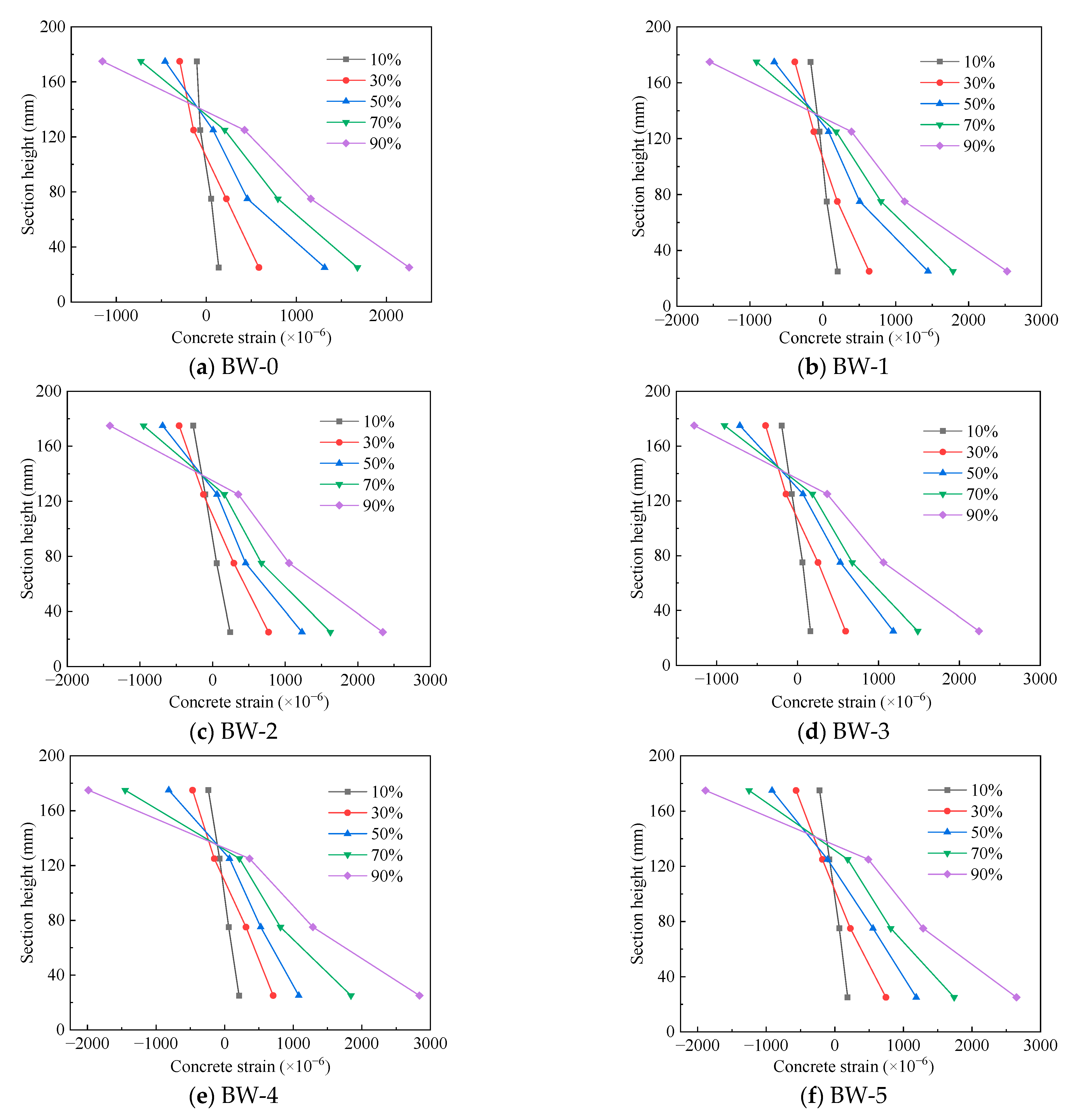
3.2.4. Concrete Strain Analysis

The concrete strain at the mid-span section of the test beam is shown in Figure 18. Based on the concrete strain gauges arranged at equal intervals at the mid-span section of the test beam, the relationship between the concrete strain at the mid-span section and the section height was observed as the external load increased. It was found that each test beam basically conformed to the assumption of the flat section. The strain of the mid-span section was approximately linearly distributed along the section height, and with the increase in the load, the height of the compression zone gradually decreased.

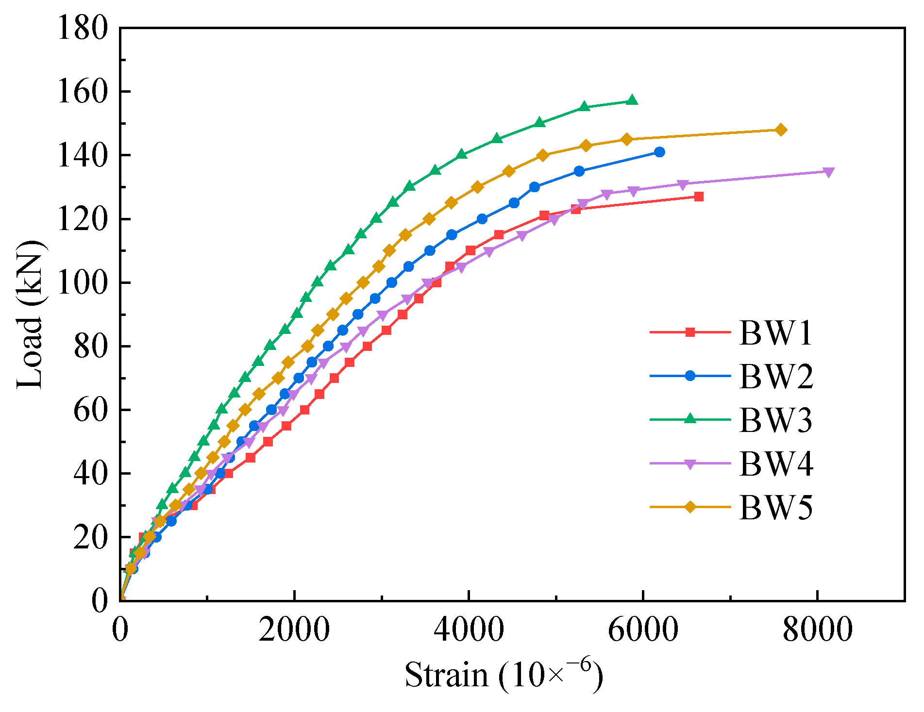
3.2.5. Strain Analysis of CFRP Sheets

The load–strain curve of the CFRP sheet of the reinforced beam is shown in Figure 19. As shown in Figure 19, before the tensile reinforcement yields, the stress of both the compressive reinforcement and the CFRP sheet increases linearly with the increase in the load. When the tensile reinforcement yields, the tensile force it bears no longer increases. The increment in the bottom tensile force caused by the increase in load is gradually borne by the CFRP sheet. The ratio of the tensile force borne by the CFRP sheet to that borne by the tensile reinforcement changes, thereby increasing the strain growth rate of the CFRP sheet in the later stage of loading. Compared with other test beams, it was found that the slope of the load–strain curve of the CFRP sheet of BW-3 was relatively large. This is because when three layers of the CFRP sheet were adhered for reinforcement, the tensile force borne by the CFRP sheet was evenly distributed, and the stress on each layer of the CFRP sheet decreased, thereby resulting in a smaller stress change in the CFRP sheet at the same load level. Furthermore, by comparing BW-1 with BW-4 and BW-2 with BW-5, it was found that when the number of CFRP sheet layers was the same, compared with the BMSC-reinforced beam, the CFRP sheet strain of the epoxy resin-reinforced beam was larger, indicating that the utilization rate of the tensile strength of its CFRP sheet was better.

4. Calculation Formula for FBC of Reinforced Beams

4.1. Failure Forms of CFRP Sheet-Reinforced Beams

The failure forms of beams reinforced with the CFRP sheet can be roughly divided into the following situations:
Failure form I: the failure of stiffened beams. Its manifestations can be classified as follows: First, after the tensile reinforcing bars yield, the concrete is crushed, and at this time, the CFRP sheet has not been broken. Second, the yield of the reinforcing bars is accompanied by the fracture in the CFRP sheet, while the concrete is not crushed; this usually occurs when the concrete beam tensile steel and CFRP sheet configuration is low. Both of the above situations belong to common forms of damage.
Form of destruction II: super-reinforcement destruction. This failure mode occurs when the compressed concrete is crushed first. At this time, the tensile reinforcement has not yet yielded, and the CFRP sheet has not fully exerted its tensile strength before failure occurs. It belongs to a brittle failure and is usually caused by the excessive reinforcement of the CFRP sheet. In actual engineering, the reinforcement amount of the CFRP sheet should be controlled to avoid over-reinforcement damage.
Failure form III: CFRP sheet peeling failure. This failure mode is manifested as follows: When the CFRP sheet undergoes local debonding with the surface concrete of the beam, and eventually, the CFRP sheet and the surface concrete peel off. In this test, to avoid peeling failure, during the process of pasting the CFRP sheet, measures such as roughening, wetting, and rolling the CFRP sheet were taken to further improve the construction quality.
In the experiments of this paper, all the beams reinforced with BMSC adhered to the CFRP sheet were properly reinforced beams. The manifestations were as follows: the concrete at the bonding point between the middle and bottom of the span and the CFRP sheet cracked, and then the concrete protection in some areas peeled off, and the concrete in the compression zone was crushed.

4.2. Establishment of the Calculations

4.2.1. Basic Assumptions

The establishment of the calculation formula adopts the following basic assumptions.
(1)
Plane cross-section assumption: The test beams basically conform to the plane cross-section assumption.
(2)
The tensile strength of concrete is not considered.
(3)
Stress calculation of concrete: The formula recommended in “Code for Design of Concrete Structures” GB50010-2010 [39] is adopted, as shown in Equation (1).
σ c = f c 1 1 ε c ε 0 n ε c ε 0 f c ε 0 < ε c ε cu
where σc and εc are the compressive stress and compressive strain of concrete, respectively; fc is the axial compressive strength of concrete; ε0 and εcu are, respectively, the strain corresponding to the peak stress and the ultimate strain.
(4)
Reinforcement stress calculation: Assuming that reinforcing bars are ideal elastoplastic materials, the calculation is shown in Equation (2).
σ s = E s ε s ε s ε y σ s = f y ε s > ε y
(5)
Stress–strain relationship of CFRP sheet: Assuming that the stress–strain relationship of the CFRP sheet is linear, the calculation is shown in Equation (3).
σ cf = E cf σ cf
In the formula, σcf and εcf are the stress and strain of the CFRP sheet, respectively; Ecf stands for the elastic modulus of the CFRP sheet.
(6)
Before the test beam reaches the ultimate load, the CFRP sheet remains effectively bonded to the surface of the concrete beam.

4.2.2. Calculation and Analysis of Flexural Capacity

Based on the test data of BMSC adhered to the CFRP sheet-reinforced beams and referring to the existing calculation methods of reinforced concrete beams, by introducing the influence coefficient γp of BMSC on the FBC, the formula for concrete beams reinforced with BMSC-applied CFRP sheets is established. Figure 20 illustrates the simplified diagram of the section bending calculation of the beam under the ultimate FBC state.
The derivation process of the calculation formula for the FBC of the normal section is as follows:
(1)
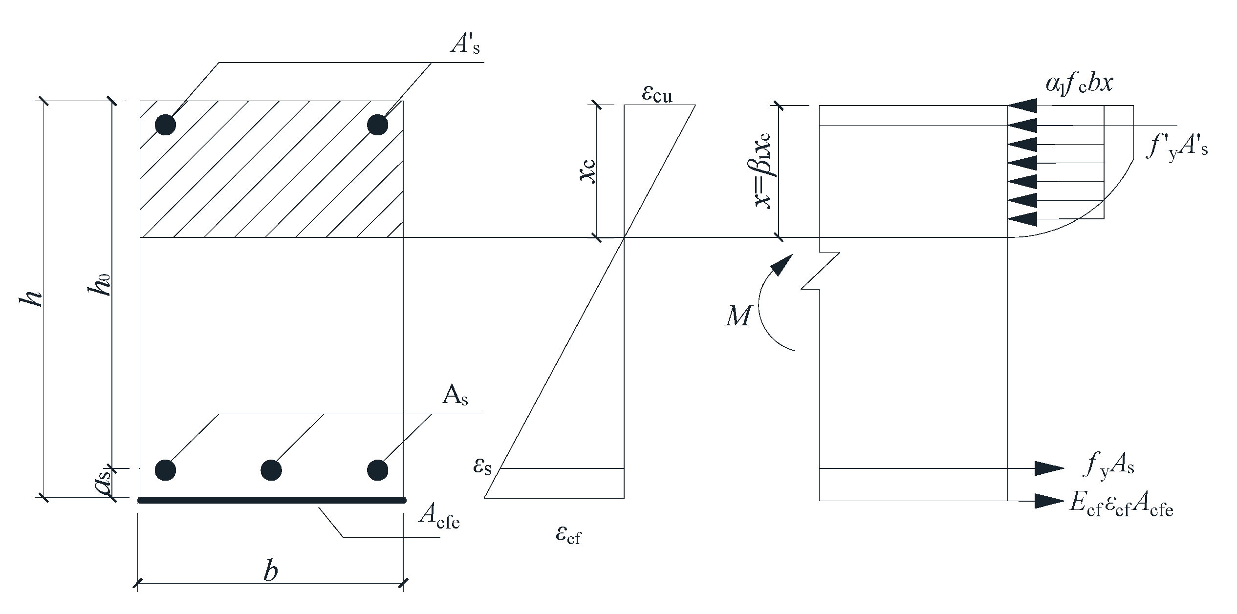
According to the force and moment balance in Figure 19, Equations (4) and (5) can be obtained, respectively.
M u α 1 f c b x h x 2 + f y A s h a f y A s h h 0
α 1 f c b x = f y A s + E cf ε cf A cfe f y A s
In the formula, Mu represents the FBC. b, h, and h0 are the width, height, and effective height of the beam section, respectively. As and As are the cross-sectional areas of the compressive and tensile reinforcing bars, respectively. Acfe represents the effective calculated area of the CFRP sheets. x represents the calculated height of the concrete in the compression zone.
(2)
Acfe takes into account the influence of multi-layer CFRP sheets on the FBC, which can be calculated by Equation (6), where Acf is the actual area of the CFRP sheet. In Equation (6), km is the thickness reduction coefficient of the CFRP sheet, which can be calculated according to GB 50367-2013 “Code for Design of Reinforcement of Concrete Structures” [40], as shown in Equation (7). In Equation (7), tf1 represents the single-layer thickness of the CFRP sheet; nf represents the number of layers of the CFRP sheet.
A cfe = k m A cf
k m = 1 . 16 n f E c f t f 1 308000 0 . 90
(3)
The theoretical strain value of CFRP can be obtained by assuming the planar section, as shown in Equation (8). Among them, β1 is the ratio of x to the actual height xc of the concrete compression zone.
ε cf = ε cu β 1 h x 1
(4)
Since Equation (8) is obtained based on the idealized plan and section theory, and the thickness reduction coefficient of CFRP sheet in Equation (7) is derived from the test results of organic adhesives, in order to improve the calculation accuracy of the FBC formula, this paper introduces the influence coefficient γp of BMSC on the FBC to correct the FBC formula. Combining Equations (6)–(8), Equations (4) and (5) were, respectively, revised to Equations (9) and (10).
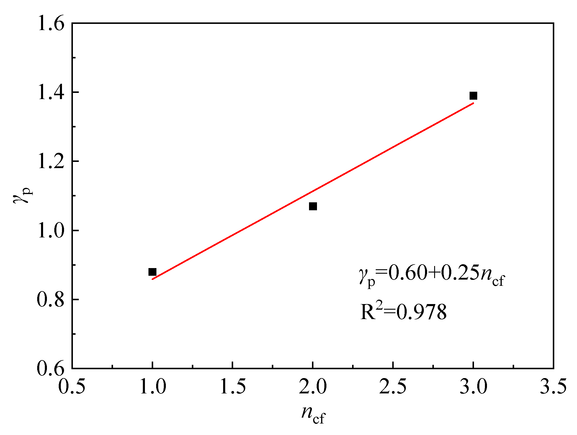
M u = f y A s h 0 x 2 + k m γ p E cf ε cu β 1 h x 1 A cf h x 2
α 1 f c b x = f y A s + k m γ p E cf ε cu β 1 h x 1 A cf
(5)
According to the test results of the reinforced beams BW-1, BW-2, and BW-3, with different numbers of layers of sheet materials pasted by BMSC in this paper, the γp values can be solved simultaneously by Equations (9) and (10), which are 0.88, 1.07, and 1.39, respectively. Taking the number of CFRP sheet bonding layers as the independent variable, the γp values of the reinforced beams BW-1, BW-2, and BW-3 were linearly fitted with the number of CFRP sheet bonding layers, as shown in Figure 21. The calculation formula of γp can be obtained as shown in Equation (11).
r p = 0 . 60 + 0 . 25 n cf
Combining the above analyses, the BMSC-pasted CFRP sheet-reinforced concrete beam bending capacity can be calculated by Equations (9)–(11).

4.3. Accuracy Analysis of the Calculation Formula

4.3.1. Verification of the Calculation Results of the Formulas in This Paper

The test results of the beams reinforced by bonding CFRP sheets with BMSC in this paper were substituted into Equations (9)–(11). Table 6 presents the statistical outcomes of the computed value F u c alongside the test value F u t obtained. It is indicated from Table 5 that the test values of the FBC of the normal section of the BMSC-adhered CFRP sheet-reinforced beam are close to the theoretical values, with a maximum relative error of 0.8%. The test values of the FBC of the BMSC-adhered CFRP sheet-reinforced beams are reported to align closely with the theoretical values. The formula established can be used to calculate the FBC of the BMSC-adhered CFRP sheet-reinforced beam.

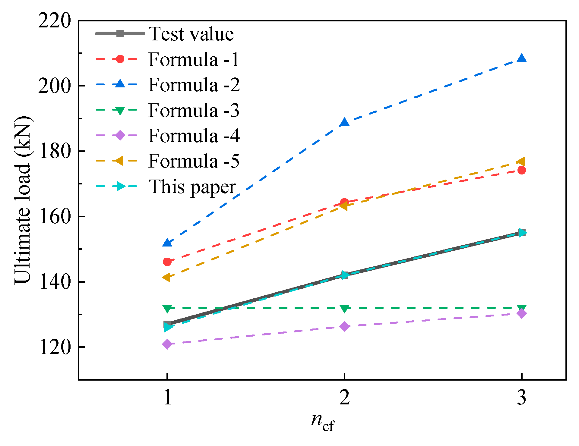
4.3.2. Comparison of Existing Calculation Formulas

This paper summarizes the representative national norms of various countries and the calculation formulas for the FBC of concrete beams reinforced with CFRP sheets proposed by researchers. The flexural capacity Mu can be obtained based on the force balance of the cross-section. That is, on the basis of calculating the FBC of the original reinforced concrete beam, the flexural capacity contributed by the tensile force Fcf borne by the CFRP sheet is superimposed, and it can be calculated according to Equation (4). However, there are still differences in the calculation methods for the tensile force value Fcf borne by CFRP sheets. The specific differences are as follows:
(1)
Formula (1): recommended in GB 50367-2013 “Code for Design of Reinforcement of Concrete Structures”.
The “Code for Design of Reinforcement of Concrete Structures” suggests the value of Fcf for the bonding of flexural members with CFRP as shown in Equations (12) and (13).
F cf = ψ f f f A cfe
ψ f = 0.8 ε cu h / x ε cu ε f 0 ε f
In the formula, ψf is the strength utilization coefficient of the CFRP sheet. When ψf > 1, take ψf = 1. εf represents the tensile strain of the CFRP sheet. ff represents the tensile strength of the CFRP sheet. εf0 represents the hysteresis strain of the CFRP sheet. When the influence of secondary force is not considered, εf0 is taken as 0. Acfe can be calculated by Equations (6) and (7).
(2)
Formula (2): recommended by the American Concrete Institute ACI 440 [41].
The American Concrete Society suggests that Fcf can be obtained by multiplying the flexural peel strain εfd by the elastic modulus Ecf of the CFRP sheet, that is, Equation (14). εfd, and the calculation formula obtained by regression based on the experimental data, is shown in Equation (15). In the formula, tf represents the total thickness of the CFRP sheet.
F cf = ε cf d E cf
ε f d = 1 60 1 E cf t f 360 , 000 0.90 f f E c f E cf t f 180 , 000 1 60 90 , 000 E cf t f 0.90 f f E c f E cf t f > 180 , 000
(3)
Formula (3): proposed by Huang et al. [42].
Huang et al. simplified the bonding stress distribution diagram at the FRP–concrete interface as a trapezoid, with the length of the bottom edge of the trapezoid being the FRP bonding extension length Ld. Fcf can be calculated by Equation (14), where the peel strain εfd is calculated by Equation (16). In the formula, τmax represents the interfacial bonding strength. Scholars such as Huang suggest taking a more conservative value, with τmax = 1 MPa.
ε f d = τ max L d + 150 2 E f t f
(4)
Formula (4): proposed by Teng et al. [43].
Teng et al. modified the in-plane shear–peel FBC design formula proposed by Chen and Teng [44] and obtained the εfd calculation model as shown in Equations (17)–(20). In the formula, fc represents the compressive strength of the concrete cylinder; bf represents the width of the CFRP sheet.
ε f d = 0.48 β w β L f c E cf t f
β w = 2 b f / b 1 + b f / b
β L = 1     L d > L a
L a = 2 E cf t f f c
(5)
Formula (5): proposed by Zhang et al. [45].
Zhang et al. proposed that the force balance formula for reinforcing concrete beams with inorganic adhesive CFRP sheets is calculated by Equation (21). εfd is calculated by Equation (23). Among them, εfe,m1 represents the effective tensile strain of the CFRP sheet when the edge of the concrete in the compression zone reaches the ultimate compressive strain, which is taken as 0.01; βcw is the influence coefficient of the width of the CFRP sheet materials.
ω f c b x = f y A s + ε f d E cf A cfe
ω = 0 . 7 + 0 . 3 ε f d / ε fe , m 1
ε f d = 0.8 E cf t f 0.16 L d β cw f t
β cw = 2.25 b f / b c / 1.25 + b f / b c
The parameters of the flexural test of concrete beams reinforced with CFRP sheets bonded by BMSC in this paper were substituted into the above formulas. The comparison results between the calculated FBC value F u c and the measured value F u t of the reinforced beams are shown in Figure 22, which illustrates that the findings derived from the formula suggested in this research demonstrate a significant correlation with the experimental results. The calculated FBC value of the ACI specification formula is relatively the largest, and the deviation from the test value is also the largest. Moreover, as the number of the CFRP sheet layers increases, the deviation between the calculated value and the measured value also becomes greater. When one layer of the CFRP sheet is adhered, the deviation is 19.45%, while when three layers of the CFRP sheet are adhered, the deviation reaches 34.39%. The calculation results of the formula proposed by GB 50367-2013 specification and Zhang et al. are relatively close, but still about 15% higher than the test values. Therefore, the above three formulas are relatively unsafe for the calculation results of the FBC of concrete beams reinforced with CFRP sheets using BMSC as the binder. For the formula proposed by Huang et al. and Teng et al. for the FBC of the reinforced beam, when the CFRP sheet is a single layer, the calculated values are relatively close to the test values, with errors of 3.94% and 4.80%, respectively. However, when the CFRP sheet is in two and three layers, the error is relatively large (more than 10%), and the error value also increases accordingly with the increase in the number of CFRP sheet layers. In conclusion, the calculation formula for the FBC of concrete beams reinforced with CFRP sheets bonded by BMSC proposed in this paper has good applicability and can provide a theoretical reference for this type of inorganic adhesive-bonded CFRP sheet reinforcement project. Different from the formulas provided by existing codes and researchers, the calculation model of the bearing capacity of reinforced beams in this paper considers the influence of BMSC as the binder on the flexural bearing capacity of concrete beams reinforced with CFRP sheets adhered. And on the basis of the Chinese code GB 50367-2013, it was further considered that the increase in the number of CFRP sheet layers cannot lead to a proportional increase in the flexural bearing capacity of the reinforced beam. In this paper, these two factors are transformed into the influence coefficients of BMSC and introduced into the calculation formula, thereby improving the calculation accuracy.

5. Conclusions

To improve the construction performance of inorganic adhesives used for bonding FRP sheets, make rational use of resources, and reduce carbon emissions, BMSC inorganic adhesives were prepared in this paper. Double-shear tests of bonding cement mortar test blocks to FRP sheets and four-point bending tests of bonding CFRP to reinforced concrete beams with BMSC were conducted. Based on the test results and analysis, the following conclusions are drawn:
(1)
The interface double-shear test results of BMSC adhering CFRP sheets and cement mortar test blocks show that BMSC has good adhesion to CFRP sheets and cement mortar test blocks. When BMSC was used as the binder, the shear strengths at the interfaces between single-layer CFRP sheets and two-layer CFRP sheets and cement mortar test blocks reached 77.6% and 86.9%, respectively, when epoxy resin was used as the binder. Moreover, the shear strength at the interface between BMSC and cement mortar test blocks when three layers of CFRP sheets were adhered was 11.1% higher than that when two layers of CFRP sheets were adhered. It is indicated that BMSC can effectively impregnate CFRP sheets and can be used for reinforcing CFRP sheets.
(2)
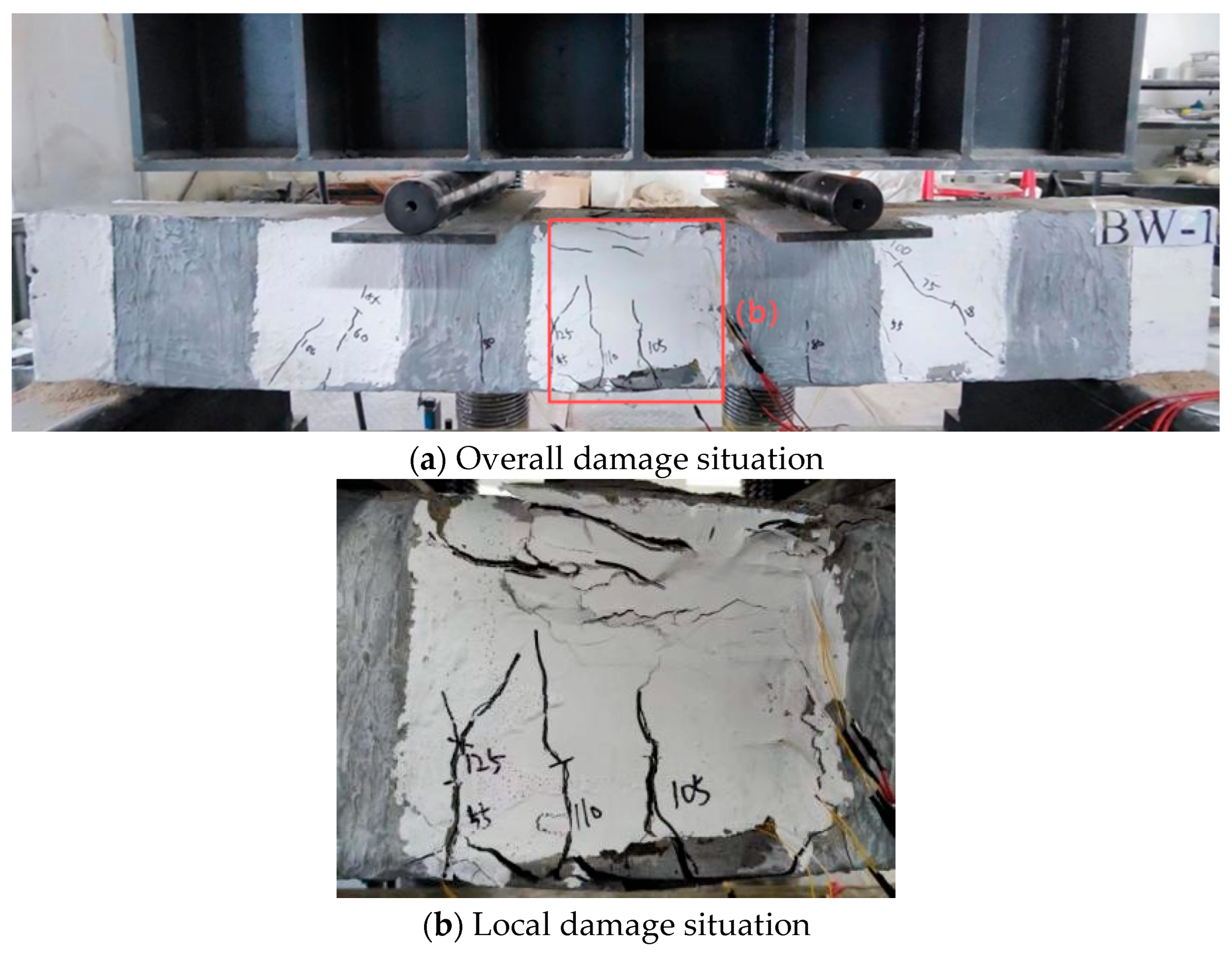
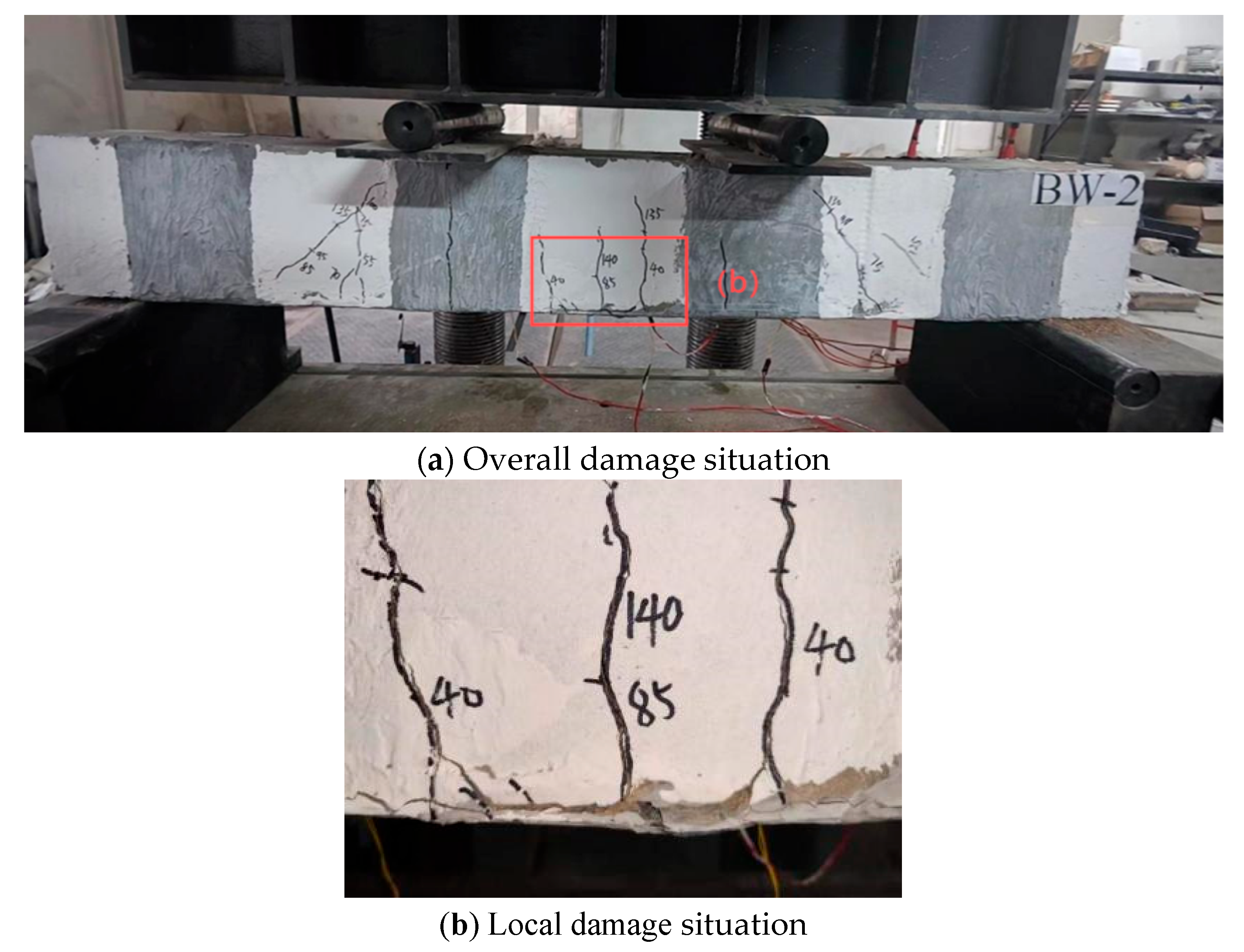
The bending failure test results of concrete beams reinforced with CFRP sheets bonded with BMSC and epoxy resin show that bonding CFRP sheets can effectively enhance the FBC and flexural stiffness of the beams and limit the development of cracks. When the BMSC-adhered CFRP sheet-reinforced beam was damaged, the concrete at the bonding area between the middle and bottom of the beam span and the CFRP sheet cracked. Immediately, the concrete protective layer in some areas peeled off, and the concrete was crushed. When the CFRP sheet was one layer, the FBC of the beam reinforced with BMSC as the binder was 17.4% higher than that of the unreinforced beam, reaching 91.4% of the beam reinforced with epoxy resin as the binder. When the CFRP sheet was two layers, the FBC of the beam reinforced with BMSC as the binder was 31.5% higher than that of the unreinforced beam, reaching 96% of that of the beam reinforced with epoxy resin as the binder.
(3)
By introducing the influence coefficient γp of BMSC on the FBC, a calculation formula for the FBC of concrete beams reinforced with CFRP sheets bonded by BMSC was established based on the test results. The empirical calculation shows that the maximum relative error between the calculated value and the test value of this formula is 0.8%. By comparing it with the existing calculation methods, this paper proposes that the calculated value of the FBC of the formula is the closest to the test value, verifying the reliability of the formula in this paper when used to calculate the FBC of concrete beams reinforced with CFRP sheets bonded by BMSC. It has reference significance for actual reinforcement projects.
(4)
The next step should be to continue the research on the shear performance of the inclined section of concrete beams reinforced with BMSC and CFRP sheets and the mechanical performance under extremely high temperature conditions.

Author Contributions

Conceptualization, L.J.; methodology, Z.Y.; software, C.Y.; formal analysis, C.Y.; investigation, Z.L.; writing—original draft preparation, L.J.; writing—review and editing, Z.Y.; visualization, Z.L. All authors have read and agreed to the published version of the manuscript.

Funding

This research was funded by Scientific Research Project of Matching Funds for Horizontal Programs from Xiamen City University of China, (No. HXPTKJ202501). This support is hereby acknowledged.

Data Availability Statement

The raw data supporting the conclusions of this article will be made available by the authors on request.

Conflicts of Interest

The authors declare no conflict of interest.

References

  1. Michel, Q.; Orozco, G.; Carter, A.; Vaillancourt, M. Influences of type and concentration of recycled mineral construction, renovation and demolition waste on the linear viscoelastic behavior of bituminous mastics. Constr. Build. Mater. 2023, 371, 130668. [Google Scholar] [CrossRef]
  2. Niu, G.; Jin, Z.; Zhang, W.; Huang, Y. Investigation of FRP and SFRC Technologies for Efficient Tunnel Reinforcement Using the Cohesive Zone Model. Struct. Durab. Health. Monit. 2024, 18, 161–179. [Google Scholar] [CrossRef]
  3. Kabashi, N.; Muhaxheri, M.; Krasniqi, E.; Murati, Y.; Latifi, F. Advancements in Fiber-Reinforced Polymer (FRP) Retrofitting Techniques for Seismic Resilience of Reinforced Concrete Structures. Buildings 2025, 15, 587. [Google Scholar] [CrossRef]
  4. Du, H.; Xian, G.; Tian, J.; Ma, Z.; Li, C.; Xin, M.; Zhang, Y. Effect of fiber surface treatment with silane coupling agents and carbon nanotubes on mechanical properties of carbon fiber reinforced polyamide 6 composites. Polym. Compos. 2024, 46, 1267–1283. [Google Scholar] [CrossRef]
  5. Yu, Y.; Liu, S.; Pan, Y.; Miu, X.; Liu, J. Durability of glass fiber-reinforced polymer bars in water and simulated concrete pore solution. Constr. Build. Mater. 2021, 299, 123995. [Google Scholar] [CrossRef]
  6. Li, C.; Xian, G. Novel wedge-shaped bond anchorage system for pultruded CFRP plates. Mater. Struct. 2018, 51, 162. [Google Scholar] [CrossRef]
  7. Wang, Y.; Jia, Q.; Surahman, R.; He, X. Static and seismic strengthening of RC frame joints by using CFRP sheets with various anchoring methods. J. Build. Eng. 2024, 82, 108309. [Google Scholar] [CrossRef]
  8. Işık, E.; Radu, D.; Harirchian, E.; Avcil, F.; Arkan, E.; Büyüksaraç, A.; Hadzima-Nyarko, M. Failures in Reinforced-Concrete Columns and Proposals for Reinforcement Solutions: Insights from the 2023 Kahramanmaraş Earthquakes. Buildings 2025, 15, 1535. [Google Scholar] [CrossRef]
  9. Eshghi, S.; Zanjanizadeh, V. Repair of Earthquake-Damaged Square R/C Columns with Glass Fiber-Reinforced Polymer. Int. J. Civ. Eng. 2007, 5, 210–223. [Google Scholar]
  10. Fukuyama, K.; Higashibata, Y.; Miyauchi, Y. Studies on repair and strengthening methods of damaged reinforced concrete columns. Cem. Concr. Compos. 2000, 22, 81–88. [Google Scholar] [CrossRef]
  11. Tsonos, A.G. Effectiveness of CFRP-jackets and RC-jackets in post-earthquake and pre-earthquake retrofitting of beam–column subassemblages. Eng. Struct. 2008, 30, 777–793. [Google Scholar] [CrossRef]
  12. Yao, Q. Experimental Study and Numerical Simulation of Seismic Strengthening for Earthquake-Damaged Piers. Master’s Thesis, Qingdao Technological University, Qingdao, China, 2023. [Google Scholar]
  13. Baloch, W.L.; Siad, H.; Lachemi, M.; Sahmaran, M. A review on the durability of concrete-to-concrete bond in recent rehabilitated structures. J. Build. Eng. 2021, 44, 103315. [Google Scholar] [CrossRef]
  14. Harle, S.M. Durability and long-term performance of fiber reinforced polymer (FRP) composites: A review. Structures 2024, 60, 105881. [Google Scholar] [CrossRef]
  15. Zhang, X.; Liu, G.; Shen, Z.; Gao, Y.; Zhou, H.; Wang, Z. A comprehensive study on the effect of reinforcing methods on the flexural behaviour of Concrete-RUHTCC composite beams. Eng. Struct. 2023, 292, 116524. [Google Scholar] [CrossRef]
  16. Fang, X.; Zhang, B.; Li, J.; Hu, L.; Chen, W. A significant comparison between magnesium-based binder and other inorganic cementitious materials for the restoration of brick-carved cultural relics. Constr. Build. Mater. 2024, 411, 134788. [Google Scholar] [CrossRef]
  17. Goufi, N.; Kaid, N.; Kerdal, D.E.D.; Idir, R. Sustainable cementitious materials: Exploring alkali-activated binders. Proc. Inst. Civ. Eng.-Constr. Mater. 2024, 177, 233–248. [Google Scholar] [CrossRef]
  18. Huang, W.; Zheng, W.; Wang, Y. Experimental study on high-temperature resistance of alkali-activated slag concrete block masonry. Adv. Struct. Eng. 2024, 27, 105–118. [Google Scholar] [CrossRef]
  19. Wang, B. Ultrahigh Toughness Cementitious Composite: Its Bond Behavior with Concrete and Structural Application for Flexural Strengthening of RC Beams. Ph.D. Thesis, Dalian University of Technology, Dalian, China, 2011. [Google Scholar]
  20. Hou, L.J.; Xu, R.; Zhang, X.F.; Zheng, R.F.; Xu, S.L.; Chen, D.; Ou, Y.F. Seismic behavior of reinforced concrete columns strengthened by textile-UHTCC. J. Build. Struct. 2022, 12, 59–69. [Google Scholar] [CrossRef]
  21. Wu, B.; Fang, S.; Feng, W. Experimental study on concrete beams strengthened with carbon fiber sheet using geopolymer. J. Build. Struct. 2012, 33, 111–118. [Google Scholar] [CrossRef]
  22. Qi, S. Experimental Study on Ambient Temperature and High Temperature Behaviors of RC Beams Strengthened with Carbon Fiber Sheet Using Geopolymers as Adhesive Agent. Master’s Thesis, South China University of Technology, Guangzhou, China, 2015. [Google Scholar]
  23. Zhang, A. Study on High Temperature Resistance Modification of Magnesium Phosphate Cement and In-Plane Shear Between CFRP Sheets and Concrete. Ph.D. Thesis, Harbin Institute of Technology, Harbin, China, 2017. [Google Scholar]
  24. Ren, J. Experimental Study on Modification of Magnesium Phosphate Cement and Reinforcement of Concrete Beams by Bonding Carbon Fiber Sheet. Master’s Thesis, Shandong Jianzhu University, Jinan, China, 2022. [Google Scholar]
  25. Fang, Y.; Zhang, L.; Hu, T.; Sun, H.; Yu, F.; Li, C. A comprehensive review on shrinkage behaviors of alkali-activated metakaolin-blast furnace slag cementitious materials: Shrinkage mechanism, properties and mitigate strategies. Case Stud. Constr. Mater. 2025, 22, e04391. [Google Scholar] [CrossRef]
  26. Yazid, M.H.; Faris, M.A.; Abdullah, M.M.A.B.; Nabiałek, M.; Rahim, S.Z.A.; Salleh, M.A.A.M.; Kheimi, M.; Sandu, A.V.; Rylski, A.; Jeż, B. Contribution of Interfacial Bonding towards Geopolymers Properties in Geopolymers Reinforced Fibers: A Review. Materials 2022, 15, 1496. [Google Scholar] [CrossRef] [PubMed]
  27. Meng, X.; Jiang, Y.; Chen, B.; Wang, L. Modification of magnesium phosphate cement with steel slag powder and ground blast furnace slag: Mechanism of hydration and electrical conductivity. Constr. Build. Mater. 2024, 438, 137305. [Google Scholar] [CrossRef]
  28. Xiao, Y.; Wang, C.; Chen, B. Understanding the role of MgO fineness on the performance of magnesium phosphate cement through multi-scale study. Constr. Build. Mater. 2024, 455, 139095. [Google Scholar] [CrossRef]
  29. Mei, Q.; Yu, H.; Ma, H.; Tan, Y.; Wu, Z. Experimental and Numerical Simulation on the Penetration for Basic Magnesium Sulfate Cement Concrete. Materials 2023, 16, 4024. [Google Scholar] [CrossRef] [PubMed]
  30. Zhao, J.; Xu, J.; Cui, C.; Yu, C.; Chang, J.; Hu, Z.; Bi, W. Stability and phase transition of 5·1·7 phase in alkaline solutions. Constr. Build. Mater. 2020, 258, 119683. [Google Scholar] [CrossRef]
  31. You, J.-J.; Song, Q.-Y.; Tan, D.; Yang, C.; Liu, Y.-F. Mechanical properties and microstructure of basalt fiber-biobased- basic magnesium sulfate cement. Cem. Concr. Compos. 2023, 137, 104934. [Google Scholar] [CrossRef]
  32. Xu, X.; Li, Y.; Sun, Y.; Yu, B.; Hu, H.; Li, D.; Hu, Z.; Wang, S.; Meng, J.; Yu, B. Investigation of the performance of basic magnesium sulfate cement mortar. Adv. Cem. Res. 2023, 35, 432–451. [Google Scholar] [CrossRef]
  33. Zhang, X.; Wu, C. Influence of Magnesium Oxide Activity on Water Resistance of Basic Magnesium Sulfate Cement. J. Adv. Concr. Technol. 2022, 20, 212–221. [Google Scholar] [CrossRef]
  34. Zhang, N.; Yu, H.; Ma, H.; Ba, M. Effects of different pH chemical additives on the hydration and hardening rules of basic magnesium sulfate cement. Constr. Build. Mater. 2021, 305, 124696. [Google Scholar] [CrossRef]
  35. Fu, Y.; Yao, X. A review on manufacturing defects and their detection of fiber reinforced resin matrix composites. Compos. Part C Open Access 2022, 8, 100276. [Google Scholar] [CrossRef]
  36. Wang, A.; Huang, M.; Chu, Y.; Zhu, Y.; Liu, K.; Guo, L.; Liu, P.; Sun, D. Optimization of mix proportion of basic magnesium sulfate cement-based high-strength coral concrete. Constr. Build. Mater. 2022, 341, 127709. [Google Scholar] [CrossRef]
  37. GB/T 17671-2021; Test method for Strength of Cement mortar (ISO Method). China Cement Standardization Technical Committee: Beijing, China, 2021.
  38. Pekgökgöz, R.K.; İzol, G.; Avcil, F.; Gürel, M.A. Experimental and Numerical Investigation of the Tendon Layout Effect on Flexural Capacity in Post-Tensioning Beams. Tehnički vjesnik 2024, 31, 1553–1560. [Google Scholar] [CrossRef]
  39. GB50010-2010; Code for Design of Concrete Structures. China Academy of Building Research: Beijing, China, 2010.
  40. GB 50367-2013; Code for Design of Reinforcement of Concrete Structures. Sichuan Provincial Academy of Building Research: Beijing, China, 2013.
  41. ACI440.2R-17; Guide for the Design and Construction of Externally Bonded FRP Systems for Strengthening Concrete Structures. American Concrete Institute: Farmington Hills, MI, USA, 2017.
  42. Huang, Y.; Ye, L. Nonlinear fem analysis of bond behavior of rc beams strengthened with bottom bonded CFRP sheets. J. Eng. Mech. 2004, 21, 54–61. [Google Scholar] [CrossRef]
  43. Teng, J.; Smith, S.; Yao, J.; Chen, J. Intermediate crack-induced debonding in RC beams and slabs. Constr. Build. Mater. 2003, 17, 447–462. [Google Scholar] [CrossRef]
  44. Chen, J.F.; Teng, J.G. Anchorage Strength Models for FRP and Steel Plates Bonded to Concrete. J. Struct. Eng. 2001, 127, 784–791. [Google Scholar] [CrossRef]
  45. Zhang, X.; Li, S.; Yang, L. Experimental study on flexural behavior of RC beams strengthened with inorganic adhesive CFRP sheets. J. Build. Struct. 2010, 31, 249–254. [Google Scholar] [CrossRef]
Figure 1. Loading diagram of the double-shear test.
Buildings 15 01980 g001
Figure 2. Construction procedures for adhering FRP sheets to the test beam.
Buildings 15 01980 g002
Figure 3. Test loading.
Buildings 15 01980 g003
Figure 4. The parameters of the test beams.
Buildings 15 01980 g004
Figure 5. The position for pasting the CFRP sheet.
Buildings 15 01980 g005
Figure 6. Concrete strain collection point in the middle section of the beam span.
Buildings 15 01980 g006
Figure 7. Strain measurement points of the CFRP sheet at the bottom of the beam.
Buildings 15 01980 g007
Figure 8. Specimen failure phenomenon.
Buildings 15 01980 g008aBuildings 15 01980 g008b
Figure 9. Shear strength of the bonding interface of the specimen.
Buildings 15 01980 g009
Figure 10. The failure situation of beam BW-0.
Buildings 15 01980 g010aBuildings 15 01980 g010b
Figure 11. The failure situation of beam BW-1.
Buildings 15 01980 g011
Figure 12. The failure situation of beam BW-2.
Buildings 15 01980 g012
Figure 13. The failure situation of beam BW-3.
Buildings 15 01980 g013
Figure 14. The failure situation of beam BW-4.
Buildings 15 01980 g014aBuildings 15 01980 g014b
Figure 15. The failure situation of beam BW-5.
Buildings 15 01980 g015
Figure 16. Ultimate loads of test beams.
Buildings 15 01980 g016
Figure 17. Test beam load–deflection curve.
Buildings 15 01980 g017
Figure 18. Test the strain of concrete in the middle section of the beam span.
Buildings 15 01980 g018
Figure 19. Load–strain curve of CFRP sheets.
Buildings 15 01980 g019
Figure 20. Simplified diagram of cross-section bending calculation.
Buildings 15 01980 g020
Figure 21. The fitting curve of γp.
Buildings 15 01980 g021
Figure 22. Comparison of the calculated values of each formula with the experimental values.
Buildings 15 01980 g022
Table 1. The strength of BMSC.
Curing Days (Day)Compressive Strength (MPa)Flexural Strength (MPa)
36511.6
77012.6
2880.514
Table 2. The mechanical parameters of various types of reinforcing bars.
TypeYield Strength (MPa)Tensile Strength (MPa)Elastic Modulus (GPa)
C12430651202
A8330520205
A6332523205
Table 3. FRP sheets’ main performance indicators.
Fiber TypeThickness (mm)Tensile Strength (MPa)Elastic Modulus (MPa)Elongation (%)
CFRP0.1734002.3 × 1051.6
BFRP0.2418701.0 × 1052.7
Table 4. Double-shear test parameters.
NumberAdhesive TypeFRP TypeNumber of Layers
E1Epoxy resinCFRP1
E2Epoxy resinCFRP2
E3Epoxy resinBFRP1
E4Epoxy resinBFRP2
B1BMSCCFRP1
B2BMSCCFRP2
B3BMSCCFRP3
B4BMSCBFRP1
B5BMSCBFRP2
B6BMSCBFRP3
Table 5. Test beam reinforcement parameters.
Test Beam NumberAdhesive TypeNumber of CFRP Sheet LayersThickness of CFRP Sheet
(mm)
BW-0No (unreinforced beams)//
BW-1BMSC10.17
BW-2BMSC20.33
BW-3BMSC30.50
BW-4Epoxy resin10.17
BW-5Epoxy resin20.33
Table 6. Comparison between experimental and theoretical values.
Test Beam Number F u c (kN) F u t (kN) F u c / F u t Relative Error (%)
BW-11261270.9920.8
BW-21431421.0070.7
BW-31551560.9930.6
Disclaimer/Publisher’s Note: The statements, opinions and data contained in all publications are solely those of the individual author(s) and contributor(s) and not of MDPI and/or the editor(s). MDPI and/or the editor(s) disclaim responsibility for any injury to people or property resulting from any ideas, methods, instructions or products referred to in the content.

