Article

Non-Conventional and Sustainable Retrofitting of Fire-Exposed Reinforced Concrete Columns Using Basalt Fiber–Engineered Geopolymer Composites

by
Ruba Palanivelu
1,
Bhuvaneshwari Panchanatham
1,*,
Adamantis G. Zapris
2,* and
Violetta K. Kytinou
2,*
1
School of Civil Engineering, SASTRA Deemed University, Thirumalaisamudram, Thanjavur 613004, India
2
Laboratory of Reinforced Concrete and Seismic Design of Structures, Department of Civil Engineering, School of Engineering, Democritus University of Thrace (DUTH), 67100 Xanthi, Greece
*
Authors to whom correspondence should be addressed.
Buildings 2025, 15(12), 1962; https://doi.org/10.3390/buildings15121962
Submission received: 28 April 2025 / Revised: 29 May 2025 / Accepted: 2 June 2025 / Published: 6 June 2025

Abstract

The increasing demand for sustainable and resilient construction solutions calls for the integration of innovative, non-conventional materials in structural retrofitting. This study investigates the use of basalt fiber-based engineered geopolymer composites (BFEGC) as a retrofitting material for fire-damaged reinforced concrete (RC) short columns. A total of 14 columns (150 mm × 150 mm × 650 mm) were cast. Two columns were used as control specimens. The remaining 12 columns were exposed to various fire conditions: 300 °C for 30 min, 600 °C for 20 min, and 900 °C for 15 min, followed by gradual (GC) or rapid cooling (RC). Among the columns, six were left unwrapped (GC-NW, RC-NW), while six others were retrofitted with BFEGC (GC-W, RC-W) and subjected to axial loading until failure. The results showed that BFEGC wrapping improved the mechanical performance of fire-damaged columns, especially at 600 °C. The 600RC-W columns exhibited 1.85 times higher ultimate load, 1.56 times greater displacement ductility, and 2.99 times higher energy ductility compared to unwrapped columns. The strength index and confinement coefficient of the 600RC-W columns increased by 2.31 times and 40.2%, respectively. Microstructural analysis confirmed the formation of salient hydration products under elevated temperatures. BFEGC shows significant reduction in carbon emissions and embodied energy, compared to conventional cement-based binders for fiber-reinforced polymer systems.

1. Introduction

1.1. General

Over time, structures are exposed to various stresses and environmental conditions that can lead to deterioration or damage. To maintain their functionality and safety, retrofitting becomes necessary [1]. This need may arise due to changes in usage, wear and tear of materials, revised building codes, or construction mistakes [2,3]. Reinforced concrete structures, in particular, often require upgrades to restore strength and durability [4]. Repairs are carried out to fix damage caused by aging, environmental exposure, or accidental events, while strengthening is performed to improve the structure’s load-bearing capacity to meet current standards [5,6,7]. Moreover, the presence of various types of damage and defects necessitates the use of specific retrofitting techniques. Some of these techniques include increasing the cross-sectional area, adding supplementary supports to reduce the spans of structural components, bonding external steel plates, utilizing external post-tensioning methods, and incorporating fibers reinforced with polymer (FRP) [8,9]. Various strategies address challenges in construction, with FRP composites being a key solution, as FRP laminates or sheets are commonly used to improve structural reinforcement. The popularity of FRP stems from its exceptional strength-to-weight ratio, resistance to corrosion, and flexibility in handling and installation. These benefits make external bonding an attractive option for construction projects, allowing for quick setups and cost-effective labor [10,11]. FRP composites are primarily composed of layers of fibers embedded within an epoxy resin matrix [12]. The four primary types of fibers commonly used in FRP materials are carbon, glass, aramid, and basalt [13]. Epoxy resins offer excellent impregnation and bonding of fibers, ensuring strong adhesion and durability. However, they have drawbacks, including compatibility issues, permeability concerns, and specific processing requirements [14]. Additionally, they can be harmful to personnel and the environment, with high carbon footprints and significant embodied energy [15].
To address fire damage, strengthening methods like FRP wrapping and fire-resistant coatings enhance durability and reduce spalling. These techniques help restore structural integrity and load-bearing capacity in fire-exposed specimens. Several structures, including normal buildings, bridges and industrial facilities, frequently escape collapse in the case of a fire occurrence. In these kinds of situations, the first step is to analyze the structural safety and service conditions, and the next step regards whether the structure needs to be strengthened and repaired [16]. The majority of collapses in fire-damaged concrete structures are caused by poor detailing or, in severe situations, failure of steel reinforcement. This is due to the frequent practice of installing reinforcement on the surface of the concrete member [17]. The post-fire behavior of concrete columns under gradual and rapid cooling processes has not been studied extensively. Structural components have typically been evaluated against standard benchmarks such as EN and ASTM documents [18]. In conventional applications, organic epoxy binders that are commonly used, in FRP systems have certain drawbacks, including low permeability, a lower glass transition temperature, and diminished mechanical performance when exposed to elevated temperatures. In building structures, columns are critical elements that require post-fire repairs to restore their strength, which may be compromised due to fire exposure [19]. This repair approach is often preferred over complete reconstruction due to considerations of cost and time efficiency [20]. When subjected to high temperatures, these columns can experience a decline in mechanical properties. In addition to reduced strength, elevated temperatures can lead to significant alterations in the microstructure, influenced by varying fire intensities and durations [21].
In FRP applications, inorganic binders produce better outcomes at high temperatures. Fire-damaged structures can be repaired and strengthened using methods like FRP wrapping, external post-tensioning, fire-resistant coatings, and concrete jacketing. These techniques help restore strength, improve durability, and prevent further deterioration. As an organic binder, Engineered Cementitious Composite (ECC) is more compatible with cementitious substrates than other materials. FRP with ECC, introduced in the early 1990s, were designed to enhance tensile ductility through strain-hardening and multiple cracking behavior. Given that the production of Portland Cement contributes approximately 8% of global CO2 emissions, it is crucial for the building industry to pursue sustainable advancements, which can be supported through the continued development of ECC [22]. According to earlier research [23], it was reported that the inorganic binder of engineered geopolymer composite (EGC) is well-suited for use in anti-explosive structures due to its ability to retain integrity under impact stress without noticeable breaking or crushing. In sustainable methods of promising alternative to traditional ECC, the characteristics suggests that EGC could have extensive applications in the construction industry; however, the type of alkaline activator used significantly impacts the properties of the EGC [23,24]. The deterioration of material properties at elevated temperatures negatively affects concrete performance, a phenomenon recognized in construction materials. In particular, as the alkali ratios increase, specifically within the range of 12 mol/L, the compressive strength of the BFEGC specimens correspondingly improves. This improvement is logical, as higher alkali concentrations facilitate the geopolymerization processes during ambient curing, thus enhancing tensile strength Moreover, retrofitting through confinement has demonstrated significant enhancements in the structural performance of concrete substrates under various loading conditions [25,26]. As the number of FRP-EGC confinements increases, primary fractures tend to propagate more extensively [27]. The residual strength of fire-exposed concrete columns is significantly affected by temperature distribution and spalling caused by rapid heating. While slight strength gains may occur up to 250 °C [22], temperatures above 500 °C lead to notable reductions in yield and ultimate strength, with mechanical properties progressively deteriorating as peak temperatures increase [23]. Limited research exists on the post-fire performance of concrete columns, wrapped and unwrapped, subjected to different cooling regimes using basalt fabric-based geopolymer composites. In this study, a basalt fiber-based engineered geopolymer Composite (BFEGC) binder is combined with Basalt Fiber Reinforced Polymer (BFRP) sheets to create a unique retrofit method for fire-damaged RC columns. The BFRP–BFEGC combination showed better bonding ability and tensile strength than traditional organic adhesives, preserving structural integrity even at high temperatures. Under thermal stress, the composite shows little indications of failure. The improved mechanical and thermal performance of BFEGC as a sustainable substitute for post-fire reinforcing concrete structures was validated by a review of the literature. Both unwrapped and retrofitted RC column specimens were tested in a range of fire exposure situations, which were followed by both gradual and rapid cooling patterns. To evaluate the efficacy of the retrofitting method, structural performance parameters including ultimate load, displacement and energy ductility, confinement ratio, and strength index were examined. By exposing the interior material behavior and validating the system’s thermal loading, microstructural observations supported the mechanical results.

1.2. Research Significance

Past research has shown that retrofitting fire-damaged structural components is often more cost-effective than reconstructing them. Recently, the disadvantages of the organic matrix in FRP materials have been addressed with the development of an inorganic binder matrix. However, the retrofitting of fire-damaged columns—cooled under different conditions—using sustainable inorganic-based FRP composites without any repair techniques has not been thoroughly explored. It is important to investigate real-world scenarios where fires are suddenly suppressed and how this affects both the mechanical behavior and microstructural properties of the materials involved. Additionally, the effectiveness of basalt fiber matrices in retrofitting techniques needs to be examined. There should also be a focus on replacing traditional cementitious composites with sustainable alkali-based composites. This study aims to effectively utilize basalt fiber sheet-based engineered geopolymer composites to strengthen reinforced concrete columns subjected to elevated temperatures followed by cooling.

2. Experimental Program

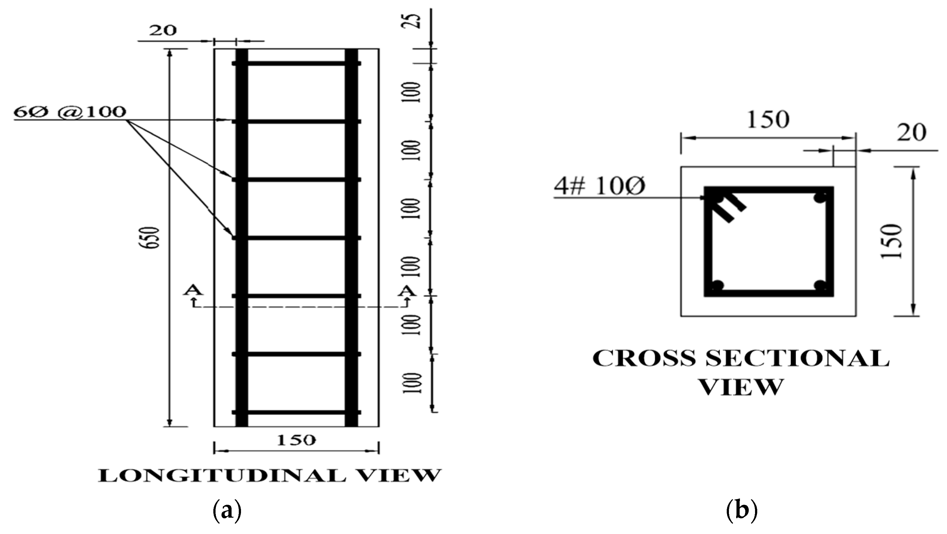
2.1. Description of the Specimens
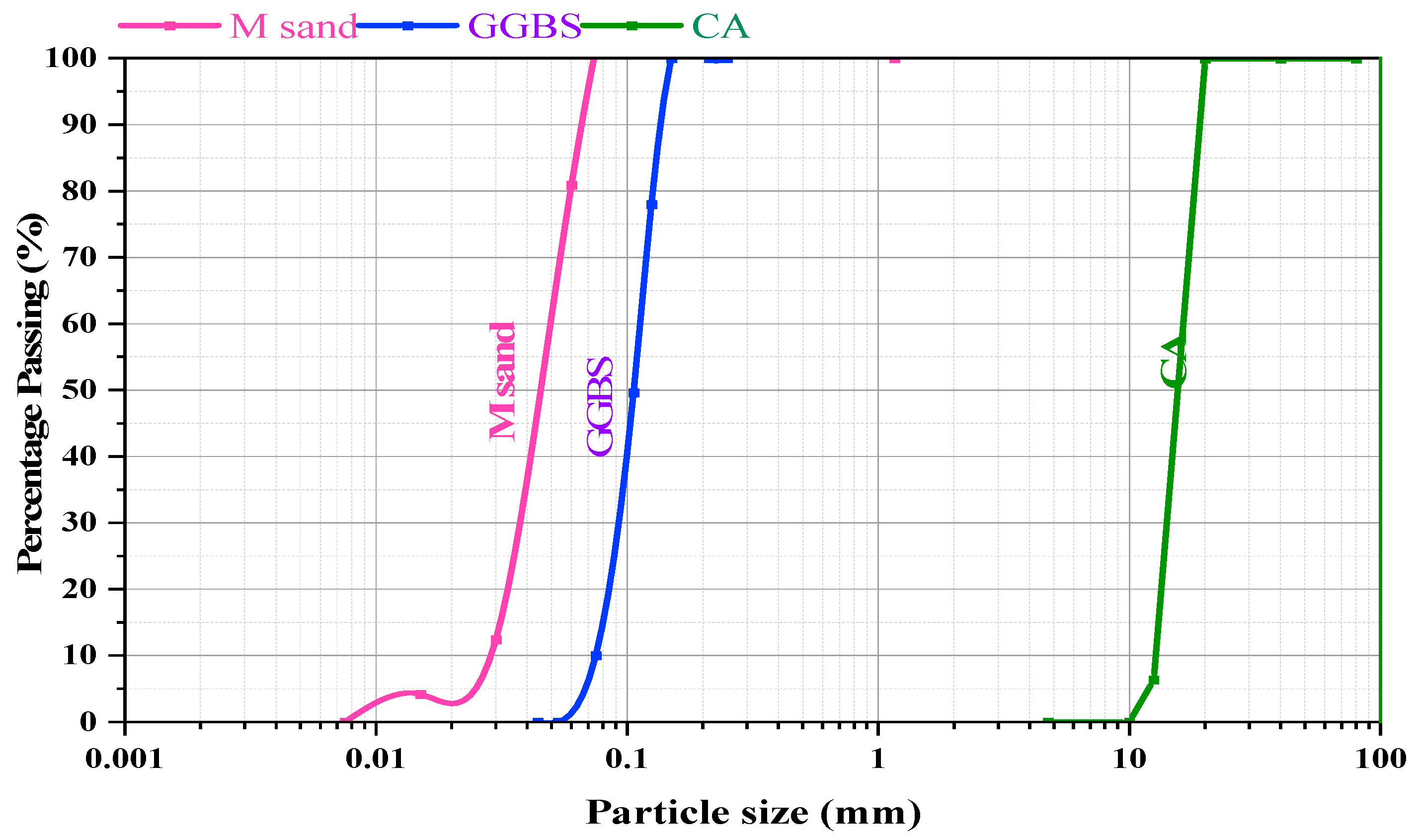
Concrete was designed to have a characteristic compressive strength of 20 MPa. The mix proportion was designed as per IS 10262-2009 [28]. The slump was measured to be 80 mm and the concrete was cast into cube molds with dimensions of 100 mm × 100 mm × 100 mm. Nine cube specimens were cast as per IS 516-1959 [29], demolded after a day, and moisture-cured for 7, 14, and 28 days for optimizing curing practices and predicting long-term durability, which helps to assess the rate of strength development. Additionally, three conventional concrete cylinders (100 mm diameter × 200 mm high) were cast, demolded, and cured to ascertain the elastic modulus of the design concrete. Nine cube samples (50 mm × 50 mm × 50 mm) (ASTM 109) were cast using BFEGC trial mixes to ascertain the characteristic compressive strength. Mix 4 was selected due to its optimal compressive strength and superior thermal resistance compared to other mixes. Since Mix 4 attained the target compressive strength, it was adopted for further specimen preparation. Cylindrical specimens (70 mm × 140 mm) were cast in accordance with ASTM C496 to evaluate compressive strength, while prismatic specimens (250 mm × 50 mm × 50 mm) following ASTM C78 were prepared for flexural strength testing. Additionally, coupon specimens (450 mm × 250 mm × 70 mm) were fabricated based on ASTM D3039-M08 to assess tensile characteristics and bond behavior, facilitating a comprehensive evaluation of the material’s performance under various loading conditions [30].
Among the 14 column specimens, two were tested as control specimens. The remaining 12 columns had different intensities of temperature (°C) and subsequent cooling applied. The temperature was fixed to follow three different ranges of thermal effects: low; medium; and high, as per ISO834 fire curve [31]. Since rapid cooling was adopted in the study, the duration of sustained temperatures are limited to avoid total disintegration of the specimens. The practical scenario for putting off fires in buildings by fire fighters would occur within half an hour, and the same is followed for the study. Four specimens were heated to 300 °C for 30 min, four specimens were maintained at 600 °C for 20 min, and four specimens were subjected to 900 °C for 15 min. Among those four columns in each case, two were subjected to rapid cooling immediately after heating and two columns were gradually cooled to room temperature.

2.2. Materials

Ordinary Portland Cement with a specific gravity of 3.12, following IS 4031-1988 [32], is used in the study. Locally procured Manufactured sand (M-Sand) was used as the fine aggregate. A nominal size of 12.5 mm crushed gravel was used as the coarse aggregate (CA). These aggregates were tested per IS 2386-1963 [33], and values complied with IS 383-1970 [34]. The specific gravity of the M-Sand and CA was 2.64 and 7.2, respectively. Figure 1 displays the gradation curve of Ground Granulated Blast Furnace slag (GGBS), M-Sand, and CA used. Table 1 shows the oxide composition of GGBS (supplier’s manual). The materials used for the construction of the strengthening materials include basalt fiber sheets with thicknesses of 0.2 mm, elastic moduli of 230 GPa and 2.1% failure strains, supplied by Astra Chemicals, Chennai, India. Table 2 shows the properties of the basalt fiber (from the supplier’s manual) and Table 3 shows the mix design of concrete.
For the optimum Mix 4 for Basalt Fiber-based engineered cementitious composites (BFEGC), an alkaline activator was obtained by mixing NaOH solution and Na2SiO3 solution following 1:1.5. The NaOH solution was made by dissolving NaOH flakes in distilled water to maintain a molarity of 12M. After 24 h, the Na2SiO3 solution was mixed with the NaOH solution, acting as the activator solution. The GGBFS and M-Sand were combined for one minute in dry conditions. The alkali activators were then carefully added and stirred for another two minutes, followed by blending Viscous Modifying Agent (VMA) and a chemical admixture for one minute. In the engineered geopolymer composite (EGC) mix, the 6mm length of chopped basalt fibers was progressively sprinkled and mixed for ten minutes until cohesiveness was achieved. The flowability of the different trial mixes of BFEGC was conducted in the flow-table apparatus as per ASTM C 1437–07, and the spread was measured [35]. Flowability was calculated as per Equation (1).
F l o w = D a v g D o D o × 100 ,
where Davg—average spread diameter (mm), and Do—original base diameter (mm).
The surface-dried cube specimens were subjected to compression in a 3000 kN-capacity CTM until failure. The compressive strength at 28 days of curing was 26.89 MPa. The Young’s modulus from the slope of the stress–strain plot was 23,248 MPa. The compressive strength of BFEGC cubes for the optimal mix shows that trial mix M4 satisfied the characteristic compressive strength of 55.34 MPa. Split tensile and flexural strengths were found at 15.5 MPa and 5.13 MPa to satisfy the code requirements.

Casting of Column Specimens

A total of 14 scaled-down RC square short columns measuring 150 mm × 150 mm × 650 mm were cast. The reinforcement consisted of four 12 mm diameter reinforcement bars, which represented 2% of the longitudinal reinforcement, along with 6 mm diameter lateral ties spaced at 100 mm center to center as per the IS 456: 2000 standard [36] to meet code requirements, ensuring adequate flexural, shear, and confinement capacity. The design complies with the minimum reinforcement ratio, preventing issues like buckling and cracking, while addressing durability and fire safety considerations as specified in the respective codes [37]. The schematic diagram of reinforcement detailing is shown in Figure 2. For each temperature group, the specimens were divided based on cooling methods: two specimens were rapidly cooled immediately after heating to represent sudden cooling, while the other two were gradually cooled to room temperature to represent natural cooling. This approach ensured variations in thermal exposure with wrapped, non-wrapped, and cooling conditions, facilitating a detailed analysis of their effects on specimens. The designated fire-loaded specimens were strengthened by wrapping them with a 4 mm thick single layer of BFEGC and a 0.2 mm thick BFRP sheet along the column’s surface. Figure 3 illustrates the schematic representation of this strengthening process. The specimens labeled 300GC_W, 300RC_W, 600GC_W, 600RC_W, 900GC_W, and 900RC_W refer to those subjected to gradual and rapid cooling after fire exposure with wrapping. The method for non-wrapped specimens and the strengthening applied after fire exposure, with both gradual and rapid cooling, is detailed in Table 4.

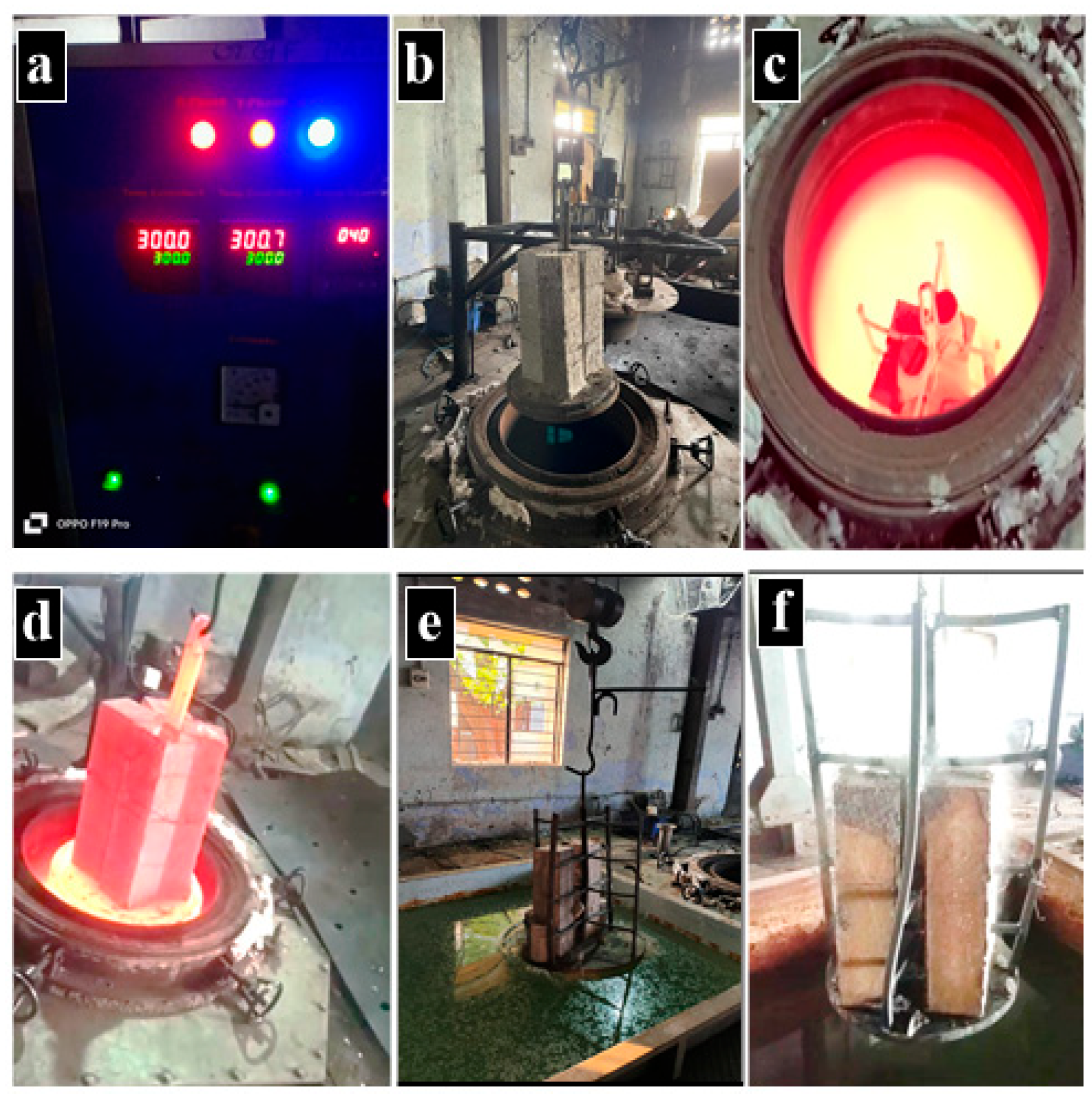
2.3. Columns Under Elevated Temperature

Twelve columns were subjected to elevated temperatures in a tempering furnace. The Cellulosic fire curve was applied as per ISO 834, shown in Figure 4. The temperature curves of the ISO834 curve can also be calculated according to Equation (2). The facility utilized is available at Metal Care, Tiruchirappalli, Tamil Nadu, with a thermal loading controller, as in Figure 5a. The furnace’s reliability in simulating the fire curves for temperature loading of scaled-down columns was verified. For regulated heating, the columns were held and positioned inside the furnace using a pulley–chain system. The loading configuration and specimen placement inside the furnace are depicted in Figure 5b and Figure 5c respectively. The temperature was adjusted to replicate a realistic fire scenario using the ISO 834 fire curve, which is commonly used in fire testing for structural materials [4,7]. To guarantee accurate heat exposure, internal temperatures were tracked during the procedure [16]. As seen in Figure 5d, the temperature was kept at the proper level for the necessary amount of time before the specimens were unloaded. The specimens were then either quickly cooled to room temperature (Figure 5e) or gradually cooled to room temperature (Figure 5f). Before being retrofitted and tested, the specimens were allowed to stabilize in the lab after cooling.
T = 20   +   345   ×   l o g ( 8 ( t )   +   1 ) ,
where T is the temperature in °C and t is the time in minutes.

2.4. Strengthening of Damaged Columns

Among the two column specimens post cooling, one column was to be axially loaded until failure without any wrapping. The other column was wrapped with BFEGC, cured at ambient temperature, and axially loaded until failure. Before retrofitting, no special repair was adopted for the heat-damaged concrete columns. The BFEGC mix was prepared as shown in Figure 6a. The basalt sheet for wrapping was cut to the required size, as shown in Figure 6b. The surfaces were wet, and a layer of BFEGC was applied as a coat before wrapping the basalt fiber sheets in the hoop direction. The single layer of wrap of BFRP sheets for the thermally affected columns was performed with the fibers in the hoop direction with an overlap of 50 mm. One more coat of BFEGC was applied and pressed smoothly to impregnate the fiber sheet properly. The finished column is shown in Figure 6c.

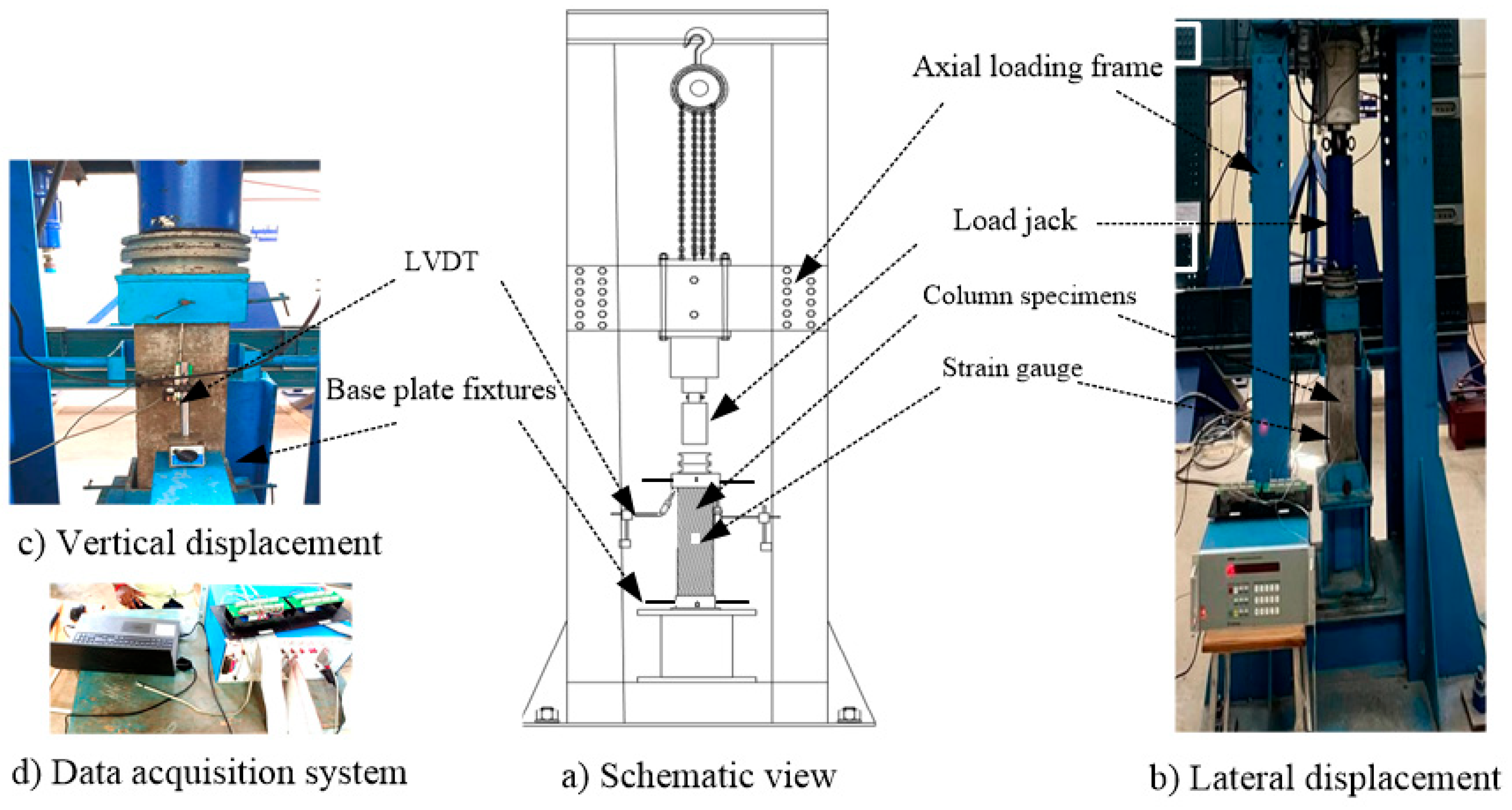
2.5. Experimental Setup

All the columns were loaded axially in a column loading frame of 1000 kN capacity. The end conditions considered were fixed for both ends. The column specimen was placed in the metal square box, and the screws were tightened to arrest the degrees of freedom. The verticality was checked using the plumb bob, and horizontal alignment was ensured using the bubble tube. The centering was made with special attention concerning the machine’s crosshead. The schematic view of loading is as per Figure 7a. An electrical strain gauge was affixed at mid height to pick up the axial strain using the data logger, as shown in Figure 7b. LVDT sensors of 50 mm in transverse length were fixed to pick up the lateral displacement in Figure 7b, and the vertical displacement in Figure 7c. The 8-channel data acquisition system to process the pickup data is shown in Figure 7d. The axial load was applied concentrically at a gradual loading rate of 1.37 kN/min. Loading was brought to a halt when reversal of loading occurred. The applied load, displacement, and strain values were noted for further parametric analysis.

3. Results and Discussion

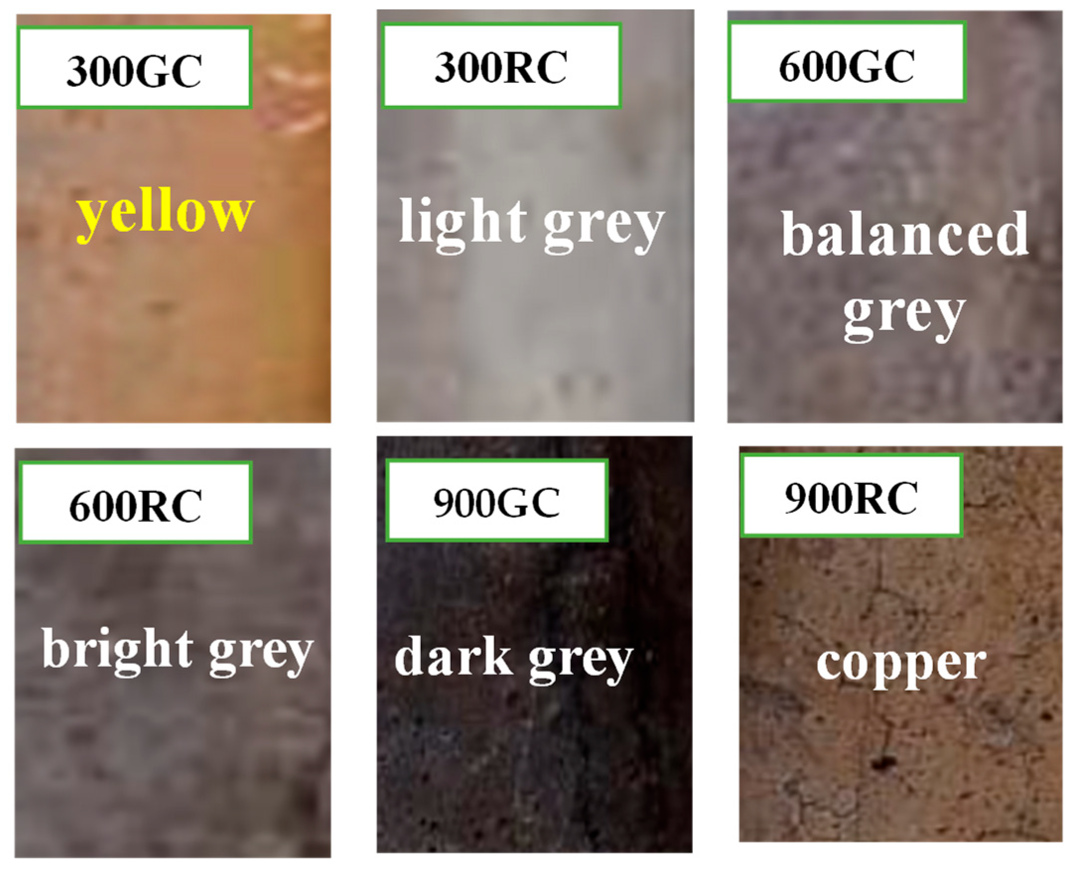
3.1. Observation During Fire Loading of Columns

Past researchers reported that deterioration in the appearance of concrete is due to the internal stress developed at elevated temperatures due to the evaporation of pore water, volumetric change, drying shrinkage, and changes in chemical composition. Specimens subjected to elevated temperatures were visually observed. The basic evaluation was conducted to observe the color modification, the pattern of crack formation, and the nature of spalling.
The initial color change was noted at 300 °C, where the color of the surface of 300GC turned to a pale yellow Figure 8. The basic cause was due to the evaporation of the bonded water, as mentioned in earlier research. Additionally, a chemical change of CaCO3 to CaO and CO2 occurred. The color transformation to yellow at 300 °C was because of CaO formation. For the 300RC columns, the color started to change to light gray. Hair-line cracks were noted on the surface for 300 °C. In the case of 600GC columns, change in color from light gray to a slightly dark grayish color occurred. Under high thermal intensity and rapid cooling conditions, the gray shades of the specimen darkened. Further, in 600 °C rapid cooling (600RC), a noticeably darker gray color was observed. At 600 °C, wider cracks start to appear in specimens. In columns subjected to high temperatures followed by gradual cooling, 900GC, a dark gray color was observed apart from minor cracks on the surface of specimens. The past research reported that the chemical reactions followed by connected pores and darker shades could be noted at higher temperatures. It was also reported that oxidation of mineral constituents was responsible for these color changes [38]. Iron oxide oxidation in cement results in grayish iron oxide compounds at high thermal load intensities. Also, carbonation of Ca (OH)2 releases dark gray calcium carbonate (CaCO3) and residual water (H2O). The intensity, duration, and pattern of cooling of the concrete could also result in color changes. When the concrete was subjected to high-intensity temperature exposure followed by rapid cooling, it could change to a copper color due to intense carbonization and oxidation. Hence, 900RC shows a copper color on the surface. Under the increased temperature intensity, apart from color change, cracks were noted on the surface of the specimens. Few surface pores accompanied the surface cracks. The widening of cracks peaked at 900 °C. The dimensions of the cracks extended, thus increasing the connectivity of pores and the severity of spalling based on the effect of elevated temperature on concrete.

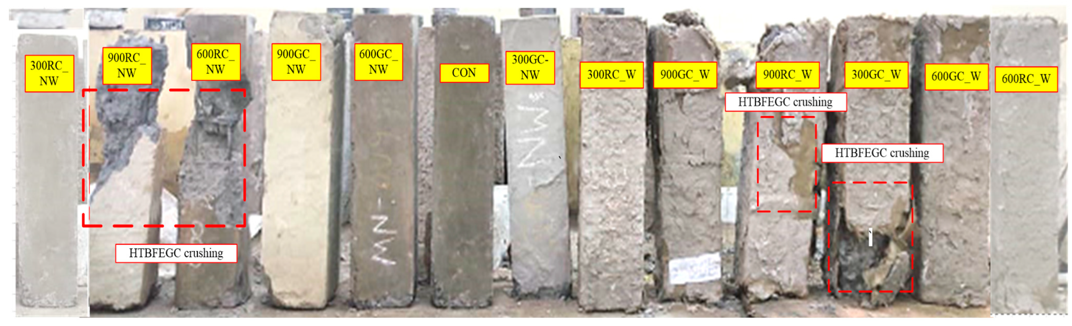
3.2. Failure Pattern of the Fired Column Under Axial Loading

The columns after being subjected to axial loading are displayed in Figure 9. Failure in the control columns was caused by the crushing of concrete at the supports due to stress concentration, which was noticed in typical axially loaded short columns. In the case of columns subjected to an elevated temperature of 300 °C, both 300GC-NW and 300RC-NW specimens exhibited a similar pattern of failure to the one noticed in control columns. In the wrapped columns in the gradual cooling condition, 300GC-W, failure was characterized by rupturing the wraps in a circumferential direction without debonding, as reported in [39], along with breakage of concrete at or near the column ends. Due to stress concentrations, the BFEGC wraps consistently failed at or close to a corner in all specimens. This most likely happened as a result of the columns’ sharp edges intensifying localized stress, which increased the likelihood of failure in those regions. In rapidly cooled conditions, referring to the 300RC-W columns only, crushing of concrete at the loaded end happened without tearing or debonding the wrap. In the columns subjected to a moderate temperature of 600 °C, under gradual cooling conditions, the 600GC-NW specimens show only the crushing of concrete at the ends where stress concentration occurred. In the case of rapidly cooled columns, 600RC-NW, complete shear failure resulted in the crushing and spalling of surface concrete. Meanwhile, for both gradual and rapid cooling conditions, the wrapped specimens, 600GC-W and 600RC-W, did not show any failure or debonding of the wrapping.
In the case of high-intensity temperature, columns that were heated to a temperature of 900 °C failed in a brittle and catastrophic manner. Cracks occurred, and cover concrete spalling began on the faces of the column. Crushing of concrete at the supports occurred in the 900GC-NW columns, followed by bulging of the rebar. Meanwhile, 900RC-NW showed brittle shear failure. In the wrapped columns under gradual cooling, 900GC-W, tearing of the wrapping occurred near the support where stress concentration prevailed. Debonding of the wrapping occurred, followed by failure of the column. In the case of rapid cooling, the wrapping provided in 900RC-W columns underwent brittle failure with complete tearing and debonding.

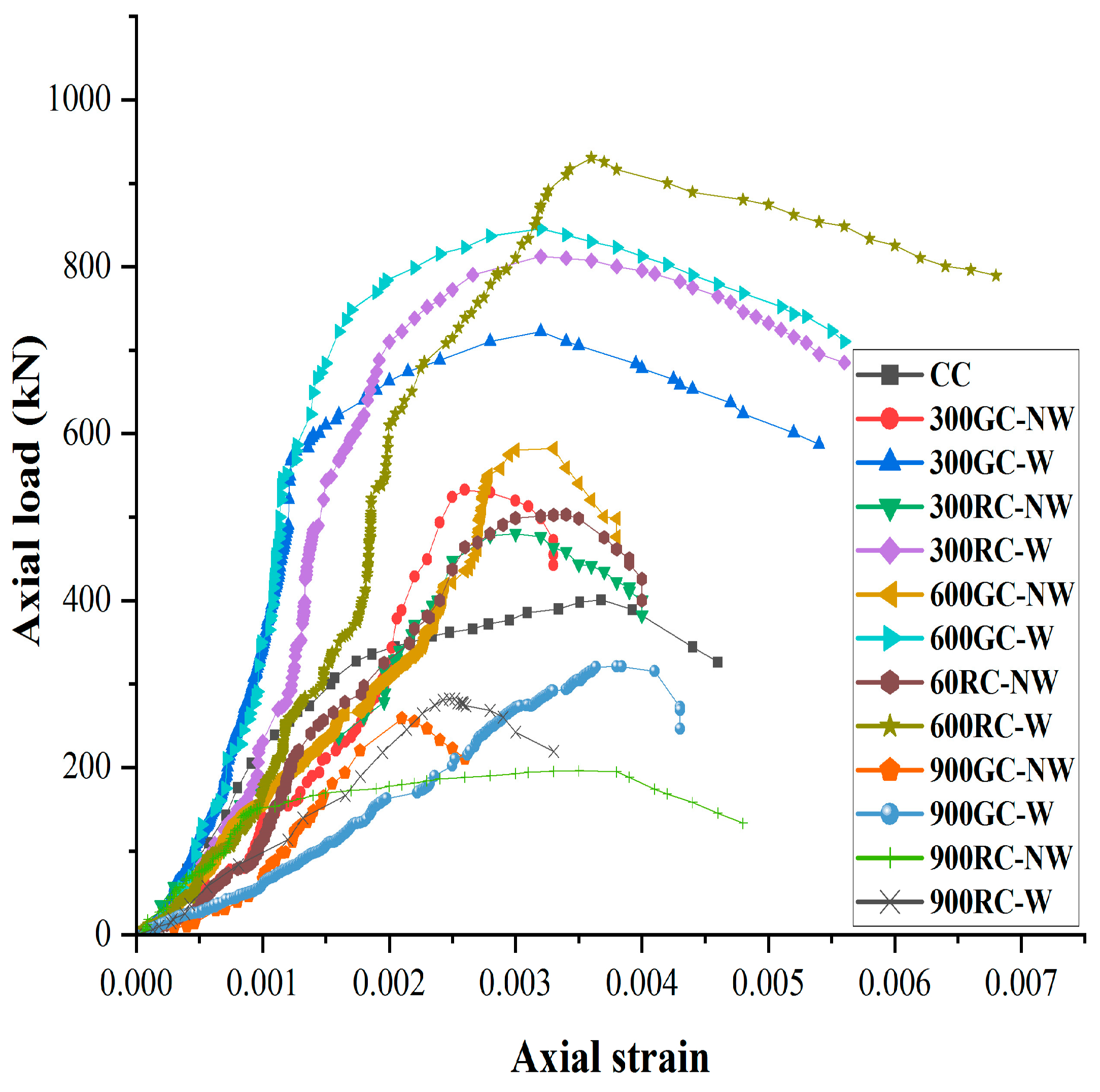
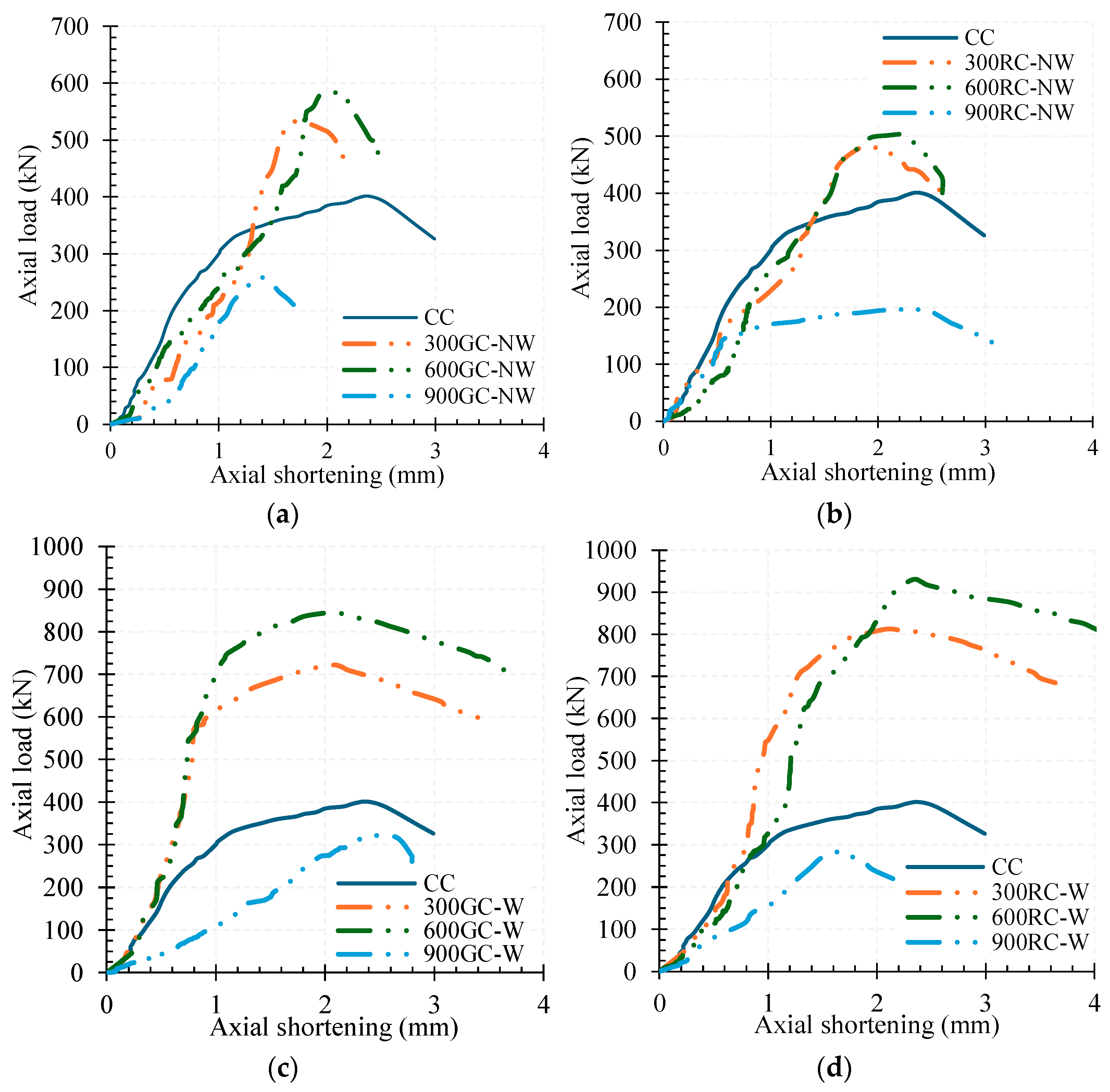
3.3. Axial Load-Axial Strain Behavior of RC Columns

Typical load–strain curves for axial load testing for control, unwrapped (NW), and wrapped columns (W) are shown in Figure 10. The axial load and strain data collected in the data acquisition system was plotted. The lateral displacement was negligible in all the tested specimens. The vertical displacement data were used to quantify the displacement ductility in the loaded specimens. All the wrapped specimens exhibited a typical curve, consistent with the findings reported in previous studies [40]. In the initial loading stage, in the column wrapped with the basalt sheet and BFEGC, the applied load increased proportionately with displacement up to 80% of the maximum load. At this stage, cracking was not formed, and the BFEGC influenced the development of circumferential hoop stresses in the wrapped layer. In the next stage of the strain hardening phase, cracking started in the BFEGC, and the circumferential stresses were shifted to the basalt sheet. Due to the confining effect, the load-bearing capacity of the column was enhanced, followed by a slight increase in the deformation capacity. The load-bearing capacity of the columns strengthened using BFEGC, and the basalt sheet was significant. The reasons are that BFEGC was a high-ductile inorganic matrix and had better impregnation efficiency. The fiber filaments embedded in EGC remained bonded, and the stress distribution in the fiber roving was almost constant, thus enhancing the confinement offered. The wrapping enhanced ductility, leading to progressive collapse without experiencing brittle failure. The core concrete was subjected to extra confinement due to the wrapping. The outward buckling of the reinforcement bars was arrested. The cooling pattern impacts the load–strain behavior of columns by affecting thermal expansion. Rapid cooling induces thermal shock, causing microcracks and weakening the structure, while gradual cooling reduces stresses and preserves load-bearing capacity.
A parametric analysis of the load–strain curve was carried out and displayed in Table 5. The influence of different parameters on the axial load-shortening behavior is plotted in Figure 11. The influence of intensity of temperature on the non-wrapped specimen is seen in Figure 11a; the influence of rapid cooling on the non-wrapped specimen is seen in Figure 11b; the influence of wrapping (with gradual cooling) is seen in Figure 11c; the influence of wrapping (with rapid cooling) is seen in Figure 11d; these are plotted to help in understanding the influence of the parameters in the load–strain behavior of columns.

3.4. Displacement Ductility of Column Specimens

Ductility is a significant factor in ascertaining the capacity of a component to resist increased plastic deflections without much decrement in strength or stiffness. The displacement ductility index ( μ D ) is evaluated as per Equation (3).
μ D = δ 0.85 u δ u ,
where δ 0.85 u is the displacement corresponding to 0.85Nu and δ u is the yield displacement. The load measured at about 85% of the maximum load in Nu in the declining graph is 0.85Nu. The yield displacement corresponds to a strain of 0.002. The concept of displacement ductility has been explored extensively by previous researchers [41]. Table 5 displays the estimated values of δ u , δ 0.85 u , and μ D for the column specimens. Figure 12. compares the effects of varied data on displacement ductility.
The retrofitted gradually cooled columns 300GC-W, 600GC-W, and 900GC-W show enhancement of 1.28-fold, 1.5-fold, and 1.01-fold, respectively, compared to unwrapped specimens 300GC-NW, 600GC-NW, and 900GC-NW. In the case of the rapidly cooled condition, compared to unwrapped columns 300RC-NW, 600RC-NW, and 900RC-NW, the retrofitted specimens show an increment of 1.3-fold, 1.56-fold, and 1.01-fold. In the case of wrapped specimens, the rapid cooling condition shows an enhancement of 1.04-fold, 1.06-fold, and 1.07-fold for 300RC-W, 600RC-W, and 900RC-W, compared to the corresponding gradually cooled columns. For the columns subjected to an elevated intensity of 900 °C, the ductility ratio was smaller than that of other specimens. The reason is due to the shear failure with reduced ultimate displacement. The comparison between wrapped and unwrapped specimens shows that the wrapping using the BFEGC layers leads to an improvement in the ductility performance of the specimens. Furthermore, although one layer of basalt sheet was adopted, the ductility index was higher for the retrofitted specimens. The comparisons have proven that BFEGC can be utilized effectively in retrofitting columns subjected to elevated temperatures and cooling.

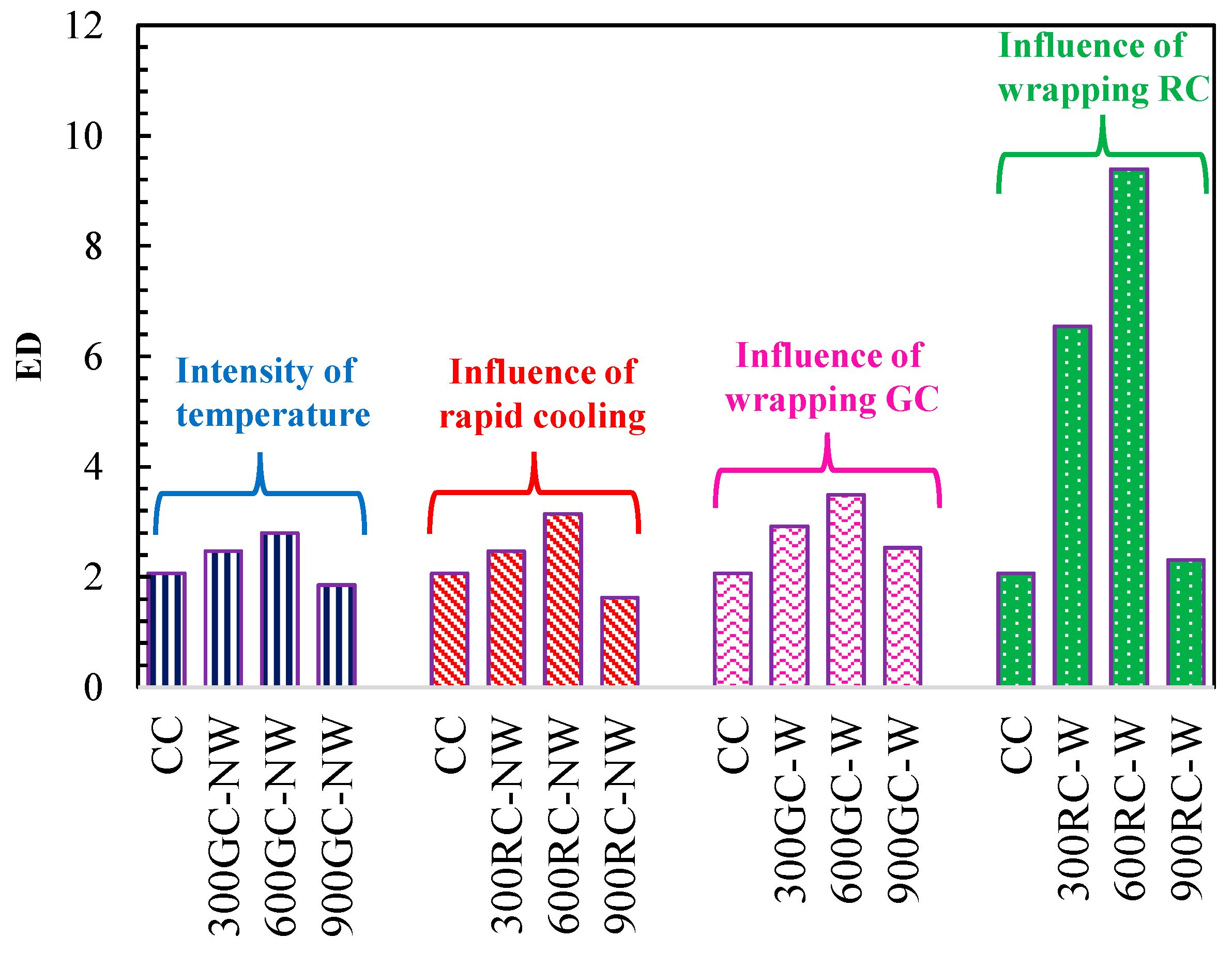
3.5. Energy Ductility of Column Specimens

Energy ductility is quantified by taking into account the influences of the different parameters (the influence of the intensity of temperature, the effect of rapid cooling, the effect of wrapping on GC specimens, and the effect of wrapping on RC specimens;) with regard to ductility, the effects of the parameters on energy ductility are compared separately in Figure 13. It is clear that the retrofitted columns have enough ductility. Among this group of columns, the energy ductility of the 600RC-W column is the best, and the 900RC-W column ranks last. To consolidate the effect of the different parameters on ductility of RC short columns, an energy ductility factor μE is evaluated as per Equation (4). The energy is quantified by integral E = ∫ Ndδ and its quantity can be estimated by quantifying the area under the load–deflection plot.
μ E = E δ 0.85 u E δ y ,
where E δ y is the energy absorbed at the yield point, and E δ 0.85 u   is the energy absorbed when the axial strain attains a value of 0.85Nu.
Qualitatively, a medium temperature, rapid cooling, and wrapping lead to better ductility. The specimens’ ductility values are evaluated and displayed in Table 5. By analyzing the results, it was noted that an increase in temperature tends to bring down the ductility index of short columns, which matches the findings of past research [42]. The retrofitted gradually cooled columns 300GC-W, 600GC-W, and 900GC-W show enhancements of 1.18-fold, 1.25-fold, and 1.36-fold compared to specimens 300GC-NW, 600GC-NW, and 900GC-NW. In the case of the rapidly cooled condition, compared to unwrapped columns 300RC-NW, 600RC-NW, and 900RC-NW, the retrofitted specimens show an increment of 2.65-fold, 2.99-fold, and 1.42-fold, respectively. In the case of wrapped specimens, the rapid cooling condition shows an enhancement of 2.24-fold and 2.69-fold, respectively, for 300RC-W and 600RC-W specimens, compared to the corresponding gradually cooled columns, whereas for 900RC-W, there was not much difference in the behavior compared to 900GC-W specimens. For the columns under an elevated temperature of 900 °C, the energy ductility was smaller than that of other specimens. The increased temperatures lead to multiple cracks and spalling in concrete. A comparison between wrapped and unwrapped specimens shows that the provision of BFEGC layers results in the flaring of the deflected curve, ensuring the enhancement of the energy ductility of the columns. Furthermore, although one layer of basalt sheet was utilized, the energy ductility was higher for the retrofitted specimens up to a medium temperature of 600 °C. For specimens subjected to high temperatures, the proper repair technique followed by wrapping would result in an enhanced energy ductility index. At times, better deformation capacity caused μD to rise with confinement, but early debonding or stiffness loss prevented μE from following proportionately. This pattern is comparable with results from a previous study [43], which found that strain localization and early failure at interfaces caused irregular ductility responses in FRP-retrofitted systems.

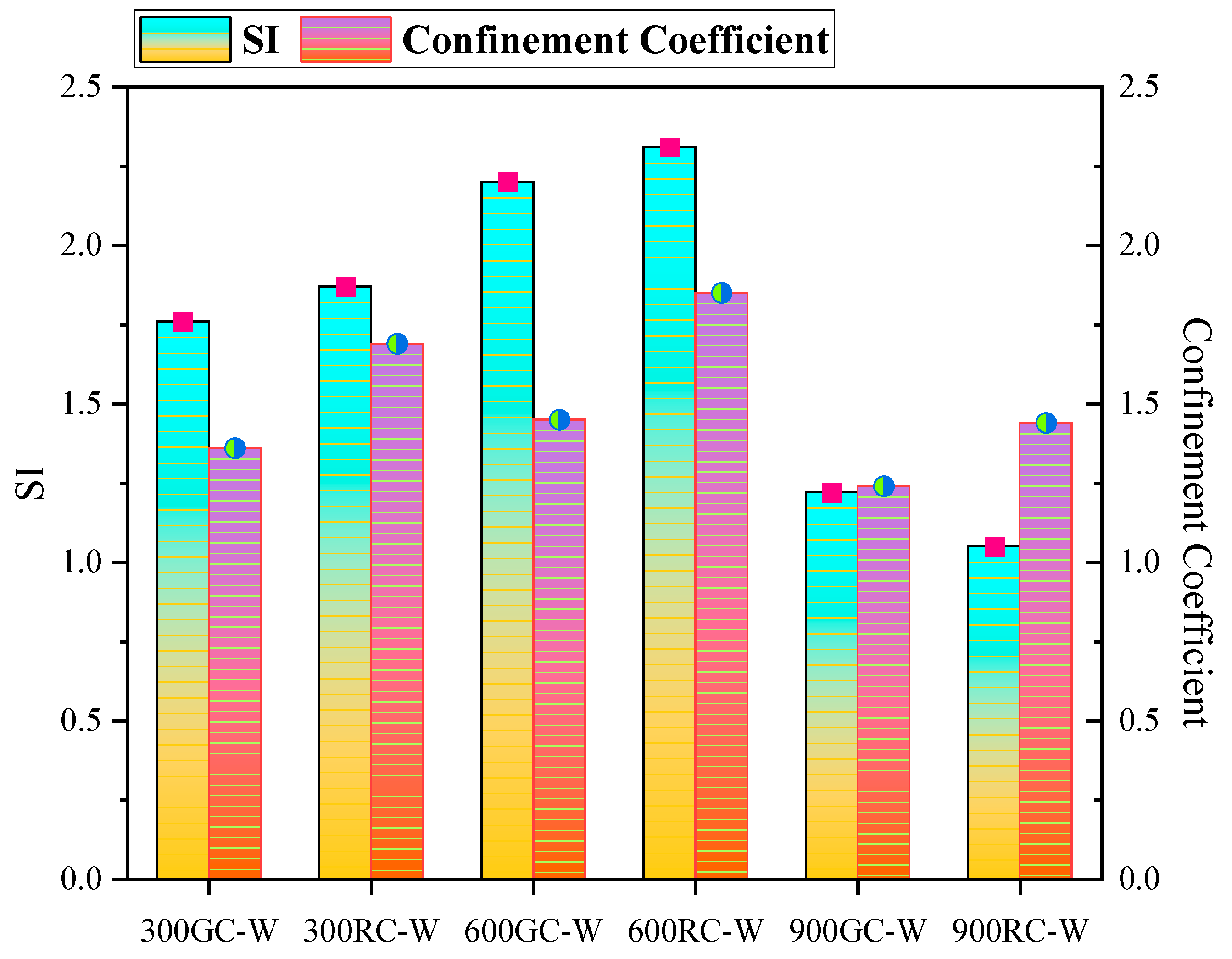
3.6. Confinement Effect of Basalt Sheet

A strength index (SI) [42] was adopted to estimate the confinement offered by the basalt sheet. The SI was quantified as the ratio of the load-carrying capacity of wrapped columns to the addition of the ultimate load of each component without accounting for the confinement offered by the basalt sheet. The SI is quantified as follows:
S I = N u N c o + N B F E G C ,
where Nco is the load-carrying capacity of the conventional column, which can be expressed as follows according to [30]:
N co = 0.45 f ck A c   +   0.67 f y A sc ,
where A c is the area of the concrete (mm2), A s c is the area of steel reinforcement (mm2), f c k is the characteristic compressive strength of the concrete (N/mm2) and f y is the yield strength of the steel (N/mm2). N B F E G C is the load resisted by BFEGC and is quantified based on Equation (7), as mentioned by [42]:
N B F E G C = 0.95 A B F E G C f c k , B F E G C ,
where ABFEGC is the cross-sectional area of BFEGC, fck,BFEGC is 0.76 (compressive strength of BFEGC cubes) and 0.95 is the conversion factor for dimension.
The SI calculated are compared in Table 5. The influence of parameters on the SI of the basalt sheet is compared in Figure 14.
The confining effect of the basalt sheet varies with the intensity of temperature and cooling pattern. Compared to gradually cooled columns, the confinement was enhanced in rapidly cooled specimens. In gradually cooled samples, up to a moderate intensity of 600 °C, the variation in the strength index was minimal. The reason might be the maximum load shared by the concrete and reinforcement. The load transfer to BFEGC, followed by the basalt sheet, was limited. For specimens subjected to high temperatures, the load-bearing capacity of the column was limited due to the deterioration of concrete in the form of cracking and spalling. Therefore, load sharing and confinement offered by the basalt sheet were enhanced. The improvement in the microstructure of rapidly cooled concrete up to 600 °C results from thermal treatment, which densifies the structure, enhances bond strength, reduces microcracks, and refines the pore structure, boosting strength and stability. Thus, along with withstanding greater loads, the columns also exhibit effective confinement without any signs of debonding. The increased strength index values reveal the same. In the 300 °C case, the enhancement of SI varied for gradual and rapid cooling conditions. The improvement for 300RC-W is about 1.06-fold compared to 300GC-W. An equal improvement was noted in 600RC-W columns. The enhancement of SI varied based on the intensity of thermal loading conditions. The specimen 600GC-W shows an enhancement of 1.25-fold compared to 300GC-W. A similar improvement of 1.23-fold was noted in rapidly cooled specimens 600RC-W, compared to 300RC-W. In the case of a high temperature of 900 °C, the gradually cooled samples 900GC-W show an improvement of 1.16-fold, compared to 900RC-W specimens. For specimens subjected to high temperatures followed by rapid cooling, a proper repair technique before retrofitting could further increase the effectiveness of the confinement provided by the basalt sheet without any debonding.

3.7. Confinement Coefficient

The expression calculates the effect of confinement offered by the retrofitting as per Equation (8) [44]:
ξ c = N w T N N W T ,
where NwT is the maximum load resisted by the wrapped thermally loaded columns and NNwT is the maximum load resisted by the unwrapped thermally loaded columns.
The influences of the parameters on the confinement coefficient are compared in Figure 15. After the column has resisted the maximum load, the wrapping starts to offer confinement. The additional load resisted by the combined effect of BFEGC and the basalt sheet could be evaluated based on the ratio of the load resisted by the wrapped and unwrapped columns. In gradually cooled specimens, compared to 900GC-W, the percentage enhancement in the confinement coefficient for 600GC-W and 300GC-W is 16.93% and 9.67%, respectively. Meanwhile, for rapidly cooled specimens, compared to 900RC-W, the percentage enhancements in the confinement coefficient for 600RC-W and 300RC-W are 28.47% and 17.36%, respectively. The increased intensity of temperature resulted in the loss of cohesiveness of the columns. The loss of integrity was severe in the case of gradual cooling compared to rapid cooling.

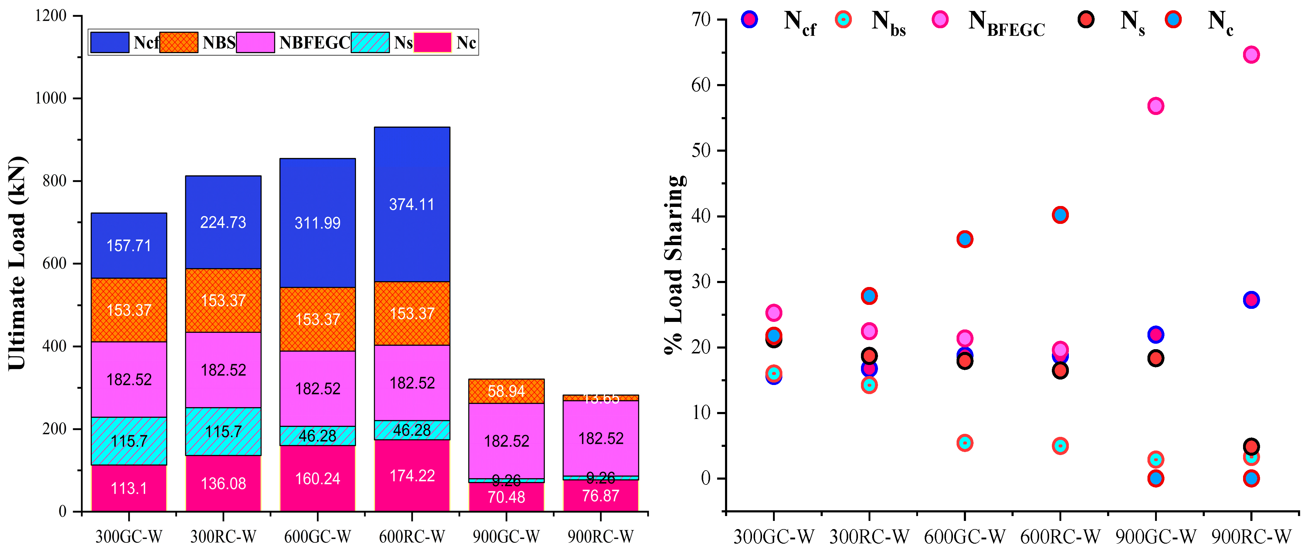
3.8. Contribution of Basalt Sheet on Column Axial Capacity

The core concrete, steel reinforcements, BFEGC, basalt sheet, and confinement of core concrete participated in resisting the applied load of the retrofitted columns [42]. Due to the confinement offered by the BFEGC and basalt sheet, the core concrete was under a combined triaxial state of stress under load application. Thus, an equation based on the capacity of the strength and confinement of the materials was arrived at as per Equation (9):
N up = N c   +   N s   +   N BFEGC   +   N BS   +   N cf ,
where Nc and Ns are the loads resisted by the unconfined concrete and reinforcements. The total value shows the bearing capacity of the control column, which is equal to Nco. NBFEGC and NBS are the loads shared by BFEGC and Ncf are the basalt sheet confinement, respectively. Based on compression test results, Ombres et al. [44] derived the confinement model for textile-reinforced mortar (TRM)-wrapped concrete, while ACI 549.4R-13 [45] recommended a model for TRM confinement using carbon-based materials. The authors noted that the model proposed by ACI was comparatively more reliable in predicting NFRP. Thus, the ACI models were used to determine the bearing capacity of the wrapped columns’ basalt sheet (NBS).
The model was used to predict the NBS as per Equation (10). The expression to calculate flu is as per Equation (11):
N BS = 3.1 ( f lu ) ( A c ) ,
f lu = 2 n k ε E A D c b
where flu is the confining pressure by the basalt sheet, Ac is the area of confinement, ε is the strain in basalt fiber, E is the elastic modulus of basalt fiber sheet, A is the area of basalt fiber, Dc is the diameter of the core concrete and b is the pitch of fiber yarns. In past research on TRM confinement [46], the k was assumed to be 0.5. Earlier research on basalt sheet-reinforced EGCs for retrofitting of thermally loaded RC was limited. Load-bearing capacity is compared in Figure 15.
Figure 15. Load-bearing capacity.
Buildings 15 01962 g015
In the columns subjected to 300GC-W, and 300RC-W, the contribution of BFEGC, basalt sheet, and confinement was almost equal. The combined contribution offered by concrete and steel was about 31% of the total maximum load resisted by the specimens. The confinement was effective up to temperature intensity of 600 °C. Concrete and steel combined contribution was about 23% of the total ultimate load. Whereas for high-intensity temperatures, at 900 °C, both under gradual and rapid cooling, the debonding of the wrapping was noticeable—in both 900GC-W and 900RC-W specimens. Confinement contribution in load sharing is lost and the BFEGC and basalt sheet contributed to sharing the applied load.

4. Microstructural Analysis

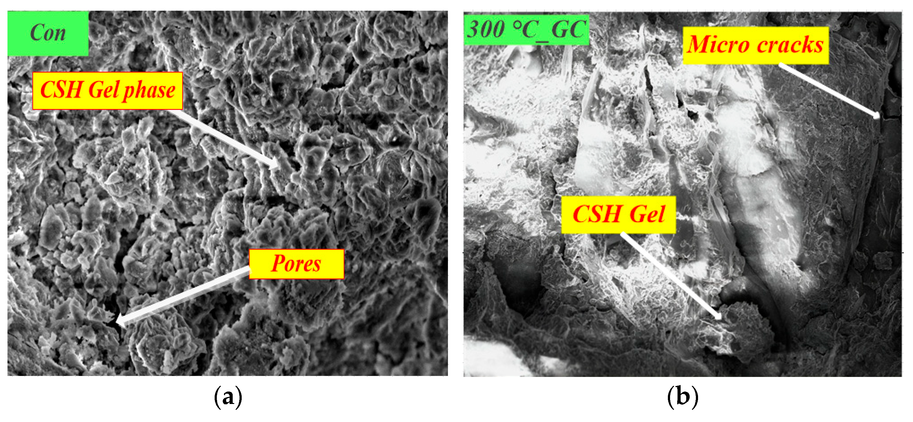
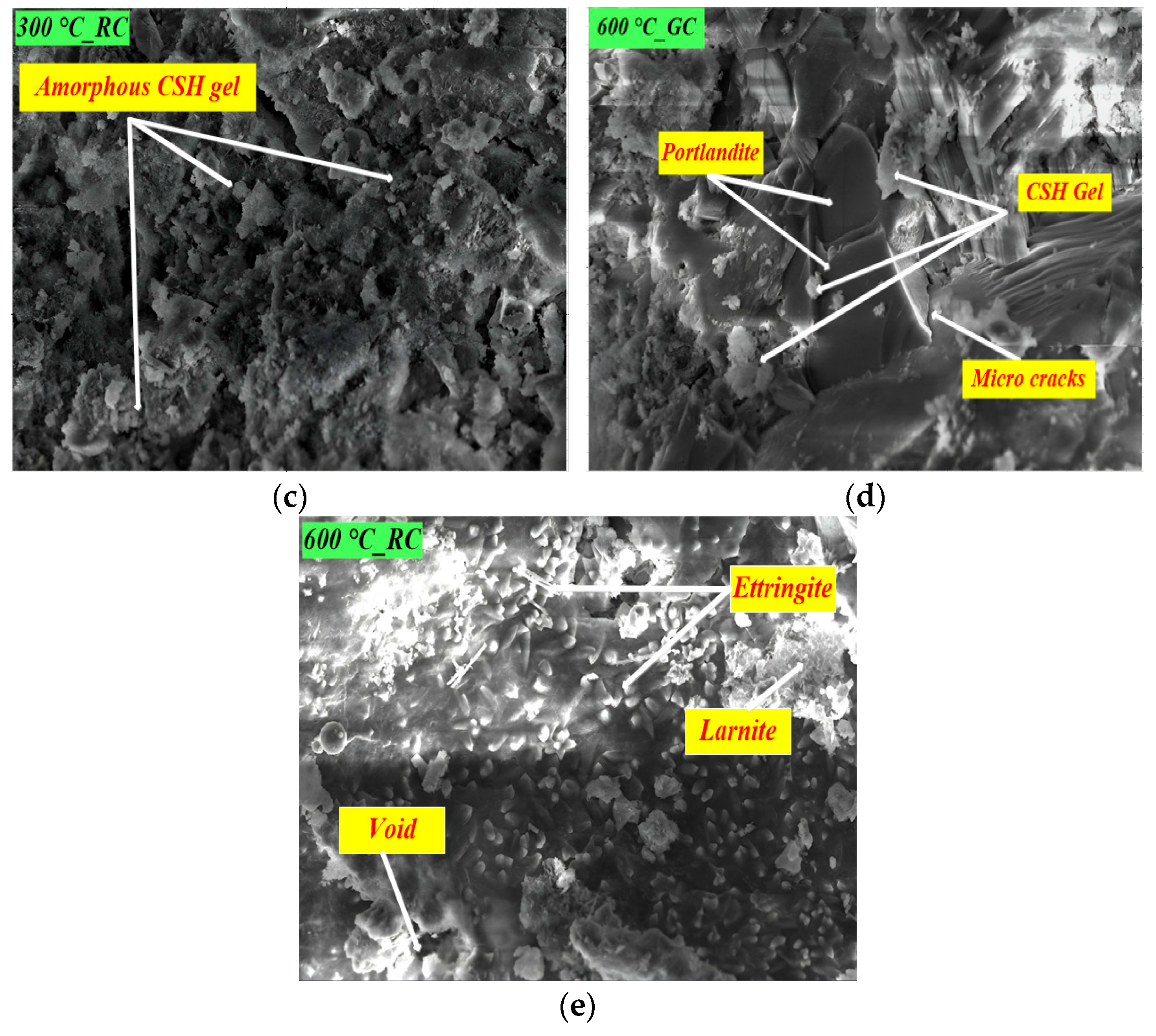
4.1. Scanning Electron Microscopy

The mechanical and durability performances of concrete highly rely on microstructures, analyzed using SEM micrographs. The micrographs obtained by Scanning Electron Microscope (SEM) show the physical processes that the concrete underwent at different temperature intensities and cooling compared to control concrete. The SEM illustration provides clear knowledge regarding the changes occurring at the micro-scale and their effects on the structural performance of the concrete. SEM analysis with Tescan Vega 3, Brno, Czech Republic, at 300KX resolution was performed on samples collected from crushed M20 grade concrete (CC, 300 °C-GC, 300 °C-RC. 600 °C-GC. 600 °C-RC) to investigate the microstructural properties. Since the columns exposed to an elevated temperature of 900 °C did not exhibit satisfactory strength characteristics, they were not considered for microstructural analysis. The SEM images (Figure 16a,b) of CC samples and 300 °C_GC, which reveal a dense microstructure with the formation of Ca(OH) mixed with C-S-H gel, along with a few pores. The rapidly cooled samples (Figure 16c,e) have a dense, and improved, microstructure. The rise in intensity of temperature to 600 °C shows the formation of amorphous C-S-H gel, crystalline portlandite, ettringite and larnite, and has fewer voids (Figure 16d,e) compared to samples subjected to 300 °C. The microstructure samples heated to 600 °C reveal increased hydration with the availability of Ca (OH)2. It can also be noted that the C-S-H underwent hydration and re-crystallization, which corroborates earlier research [47]. The gradually cooled samples show micro-cracks and changes in microstructure. The primary reasons for the increase in micro level cracks and changes in microstructure are due to the widening of pores, increase in the volume of quartz due to phase changes in aggregates, and variations in thermal strain between hydration particles reduced in volume and of the unhydrated cement matrix. The increased amount of cement hydrates, such as C-S-H gel, ettringite, and larnite in the 300 °C_RC and 600 °C_RC, respectively, ensures mechanical strength. Anhydrous phases in the form of larnite seem stable under increased temperature intensity. Thus, the increased homogenous growth in the hydrated products of the cement matrix of rapidly cooled samples enhances the durability of concrete.
According to a past study, the C-S-H matrix’s binding strength reduces to around 400 °C, followed by natural cooling, which causes cracks to appear in the concrete microstructure. Ettringite dissociates when the temperature is raised over the threshold value of 600 °C, followed by natural cooling. The SEM image of rapidly cooled samples 600 °C_RC (Figure 16e) shows ettringite, a hydrous calcium aluminum sulfate mineral crystallizing in the trigonal system. Past research [48] reveals the delayed ettringite formulation at elevated temperatures. During rapid curing, sulfate release in the slow phase from the C–S–H leads to ettringite formation at later phases. The delayed formation of ettringite fills the cracks, and reduces the porosity of and voids in the concrete. Durable concrete relies on microstructure uniformity of hydration products. Thus, the forming of a C-S-H crystalline structure and other products is a deciding factor for concrete strength and durability. Considering durability, it was found that the microstructures of 600 °C samples become denser and more closely packed, especially under rapid cooling conditions. Also, the capillary pores become reduced in size, which results in a compact microstructure with reduced permeability values.

4.2. X-Ray Diffraction

X-ray diffraction analysis was carried out to examine mineralogical compositions, focusing on the specimens exposed to 600 °C, as they exhibited satisfactory strength performance for comparative evaluation. The crystals of the samples were examined through the X-ray diffractometer (D-8, Focus Discover, Burker, Karlsruhe, Germany) to recognize the deposited phases when exposed to elevated temperatures and cooling. The crushed samples from the cube compressive strength test were finely ground and thoroughly mixed. A sample from every mix was reduced to a fine powder to pass a 75 μm sieve, and tested without further delay. The 2θ scanning range adopted for the samples was from 20° to 80°, with a step size of 0.01°/s, and a dwell time of 0.1s. The data collected were analyzed through match phase identification software and the PDF-2004 card database. The XRD for the CC, 600GC, and 600RC samples is displayed in Figure 17, where crystalline nature was detected. Compared to control samples Figure 17a, salient peaks were noted in the samples subjected to an intensity of 600 °C (Figure 17b,c). The crystalline natures of all the samples were detected. Based on experimental results in normal concrete, the XRD plot of samples exposed to 600 °C revealed prominent peaks. The dominant peaks at 2θ of 43.57° and 62.15° indicate the portlandite phase (P). The dominant peaks at 2θ of 20.68°, 21.97°, 54.16°, 63.46°, and 70.61° indicate the presence of quartz (Q). In Figure 18c, few more peaks appear due to Larnite (2θ values of 44.78°, 45.01°, 45.91°, 47.12°, 54.15°, 56.43°, and 57.16°). Larnite (C2S) is probably a result of the dissociation of C-S-H, which is consistent with the findings in the previous literature [49]. The presence of sharp peaks corresponding to portlandite (CH) and larnite (C2S) in the specimen, when compared to the control column, indicates a higher level of hydration.

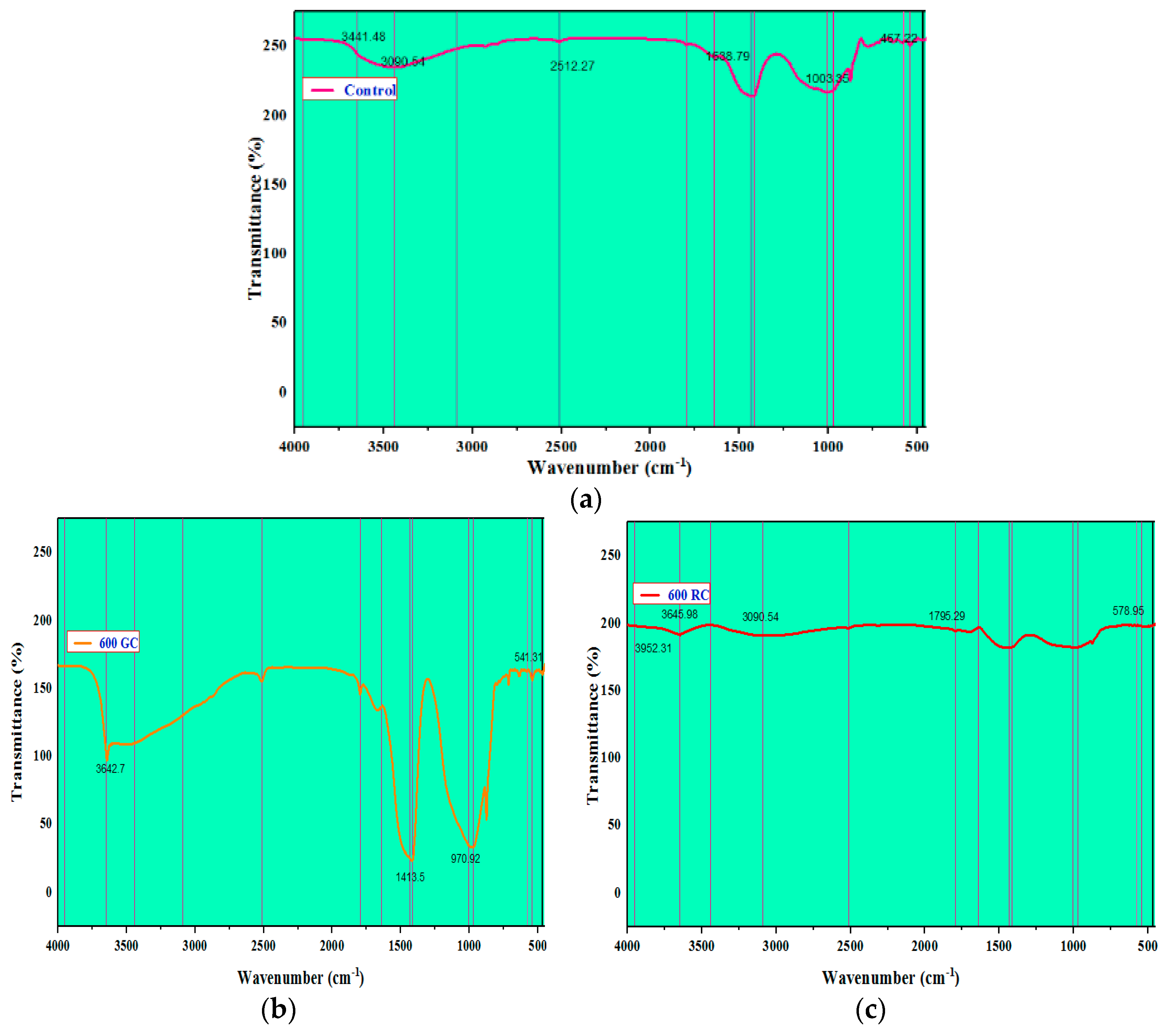
4.3. FTIR Spectroscopy

Fourier Transform Infrared Spectroscopy spectra (FTIR) analysis was carried out to describe the samples and study the pattern of changes in chemical reactions. Figure 18a, Figure 18b, and Figure 18c displays the FTIR of CC, 600 °C-GC, and 600 °C-RC samples, respectively. Since the columns subjected to an elevated temperature of 600 °C showed satisfactory strength characteristics, the corresponding samples were analyzed through FTIR analysis.
Figure 18. FTIR spectra of OPC-based fired concrete specimens: (a) CC, (b) 600GC and (c) 600RC.
Buildings 15 01962 g018
In the case of the control column, the O-H stretching of the Ca (OH)2 is responsible for the FTIR absorption peak found at 3441.48 cm−1 [50]. The band at 3090.54 cm−1 shows v1 and v2 stretching of water molecules. The absorption band at 2512.27 cm−1, 1638.79 cm−1, 1003.35 cm−1, and 467.22 cm−1 shows H-C stretching of methyl, v2 bending of water molecules, C-S-H vibrations, and S-S stretching, respectively. In the 600-GC samples, the band at 3642.7 cm−1 shows O-H stretching of the Ca (OH)2. The other significant bands at 1413.5 cm−1, 970.92 cm−1, and 541.31 cm−1 imply v3 stretching of carbonate, C-S-H vibrations, and Si-O bending, respectively. On the other hand, in the case of 600-RC samples, the absorption bands are at 3952.31 cm−1, 3645.98 cm−1, 3090.54 cm−1, 1795.29 cm−1, and 578.95 cm−1, indicating more peaks with O-H stretching of Ca (OH)2, confirming a greater degree of CH formation, v1 and v2 stretching of water molecules, v2 bending of water molecules, and Si-O out-of-plane bending, simulating the gel of C-S-H, respectively. The formation of C-S-H increases as temperatures rise [51]. The IR bands ensure the increased hydration of products in 600 °C-RC columns, compared to gradually cooled columns.

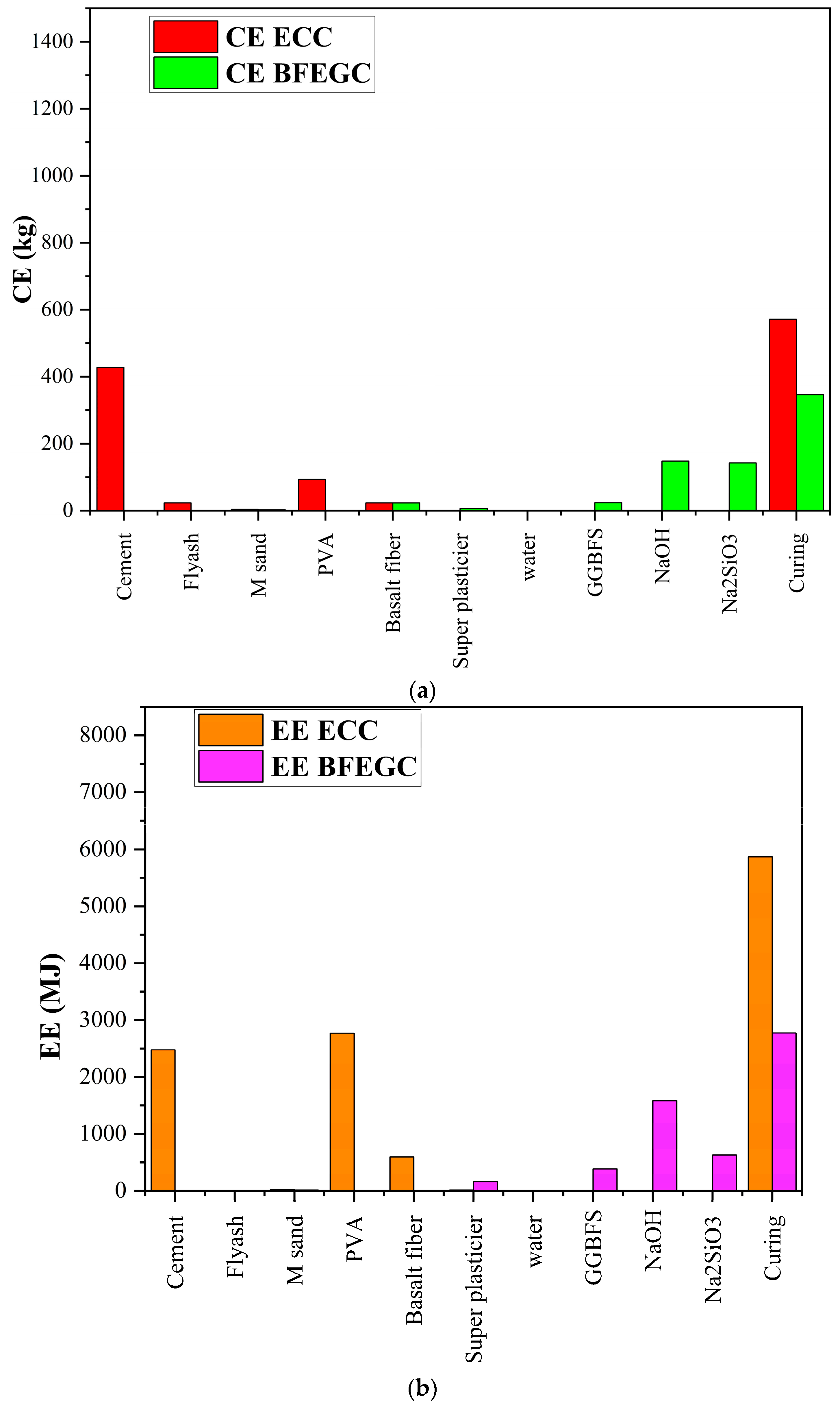
5. Sustainability of BFEGC Binders

Due to the absence of cement, the BFEGC binder is greener. The carbon footprint could be reduced, resulting in a sustainable wrapping technique. The carbon emissions (CE) and embodied energy (EE) were evaluated using Equations (12) and (13), respectively:
CE = i = 1 n M i x C O i ,
E E = i = 1 n M i x E E i ,
where n is the number of materials used; M is the material; i is the number denoting the different materials, CE and EE are factors of CO2 emission and embodied energy for different materials and are noted from relevant studies. For BFEGC, the coefficients were multiplied with the quantities applied for Mix4. The quantities of materials for ECC mix were noted and the corresponding coefficients for each material were multiplied to quantify the sustainability coefficients, as shown in Table 6.
The total value of COi and EEi of the different materials were plotted in Figure 19a,b. The sustainable BFEGC binder shows that carbon emissions and embodied energy were reduced significantly, compared to the ECC binder adopted for fiber-reinforced polymer systems. The exposed surface area of the retrofitted components would lead to a vast reduction in carbon emission, and embodied energy of buildings retrofitted using basalt fiber-based BFEGC binders.

6. Conclusions

This study examines the application of basalt fiber-based engineered geopolymer composites (BFEGC) for retrofitting fire-damaged reinforced concrete (RC) short columns. A total of 14 columns were cast, including two control specimens. The remaining 12 columns were subjected to fire exposure at 300 °C for 30 min, 600 °C for 20 min, and 900 °C for 15 min, followed by gradual (GC) and rapid cooling (RC). Of these, six columns remained unwrapped (GC-NW, RC-NW), while the other six were strengthened using BFEGC (GC-W, RC-W) and tested under axial loading until failure. Additionally, microstructural analyses using XRD, SEM, and FTIR were conducted on thermally exposed samples to assess new compound formations, crystalline phase changes, and functional group identification. The following points were observed:
  • Using an inorganic binder made from basalt fiber-based geopolymer composites has proven compatible with the underlying concrete, avoiding any issues with impregnation.
  • Rapid cooling mimics the practical scenario of extinguishing fires in buildings. Parametric analysis indicates that the effectiveness of wrapping was more significant in specimens that underwent rapid cooling after being subjected to a moderate temperature of 600 °C.
  • Compared to unwrapped columns (600RC-NW), the wrapped columns (600RC-W) demonstrated enhancements by 1.85 times for ultimate load, 1.56 times for displacement ductility, and 2.99 times for energy ductility.
  • The strength index and confinement coefficient for the 600RC-W columns showed improvements, with a value of 2.31 and a 40.2% increase, respectively.
  • The microstructure of the 600RC-W columns revealed the formation of new compounds due to the hydration of unreacted materials in the concrete when exposed to higher temperatures followed by rapid cooling, resulting in a denser matrix.
  • The performance of columns damaged by high-intensity fires and rapid cooling could be further enhanced by adopting improved repair techniques before applying the basalt fiber-based BFEGC layers.
  • The sustainable BFEGC binder demonstrated a reduction in carbon emissions and embodied energy significantly, compared to the ECC binder used in fiber-reinforced polymer systems.
This technique presents a promising solution for retrofitting reinforced concrete columns damaged due to high thermal loading and subsequent rapid cooling, the need for prior repair interventions.

Limitation and Future Scope

Future limitations in exploring this aspect of strengthening RC columns with a basalt fiber-based engineered geopolymer composite provide insights for future work. High-intensity temperature variations and exposure durations are some of the challenges that have remained unaddressed, and this limits the degradation of performance under varying thermal scenarios which are more practical. Expanding this work to include these variables to enhance the reliability of the BFEGC-based retrofitted FRP system under different fire-exposure conditions would be beneficial.
However, the research was focused on short RC columns, with BFEGC-based FRP retrofitting considered particularly suitable for this application. As it would be helpful to know how the long columns are able to withstand loads and stresses with the BFRP-based BFEGC treatment for confinement, focusing on high-intensity areas, like in beam-column joints, beams, slabs and long columns, may also allow for increases in the applicability of strengthening systems for repair and retrofitting applications. Due to practical constraints, the thermal stability of the complete retrofitted concrete assembly was not evaluated using TGA in the current study. Future research should include detailed TGA analysis of the modified structure, particularly after exposure to elevated temperatures, to better understand the thermal behavior of both the concrete substrate and the composite material. Future studies addressing these limitations could remarkably expand the strength, adaptability, and instances of use for FRP-BFEGC systems.

Author Contributions

Conceptualization, R.P. and B.P.; methodology, R.P. and B.P.; software, R.P.; validation, R.P., A.G.Z. and V.K.K.; formal analysis, R.P., B.P. and A.G.Z.; investigation, R.P., B.P. and A.G.Z.; resources, B.P.; data curation, R.P. and A.G.Z.; writing—original draft preparation, R.P. and B.P.; writing—review and editing, R.P., A.G.Z. and V.K.K.; visualization, R.P. and A.G.Z.; supervision, B.P., A.G.Z. and V.K.K.; project administration, B.P. All authors have read and agreed to the published version of the manuscript.

Funding

This research received no external funding.

Data Availability Statement

The submitted article includes all data, models, and code developed or used during the study.

Acknowledgments

The authors would like to express their profound gratitude to the Vice Chancellor and Management of SASTRA Deemed University for providing funds under the TRR research scheme for carrying out the research work.

Conflicts of Interest

The authors declare no conflicts of interest.

References

  1. Brunesi, E.; Nascimbene, R.; Casagrande, L. Seismic analysis of high-rise mega-braced frame-core buildings. Eng. Struct. 2016, 115, 1–17. [Google Scholar] [CrossRef]
  2. Xie, J.; Irwin, P.A. Wind-induced response of a twin-tower structure. Wind. Struct. 2001, 4, 495–504. [Google Scholar] [CrossRef]
  3. Qin, D.; Gao, P.; Aslam, F.; Sufian, M.; Alabduljabbar, H. A comprehensive review on fire damage assessment of reinforced concrete structures. Case Stud. Constr. Mater. 2022, 16, e00843. [Google Scholar] [CrossRef]
  4. Palanivelu, R.; Panchanatham, B.; Eszter, L.E. Strengthening of axially loaded RC Columns using FRP with inorganic binder: A Review on Engineered Geopolymer Composites (EGC). Case Stud. Constr. Mater. 2025, 22, e04590. [Google Scholar] [CrossRef]
  5. Castro, J.M.; Araújo, M.; D’Aniello, M.; Landolfo, R. Strengthening of RC buildings with steel elements. In Strengthening and Retrofitting of Existing Structures; Costa, A., Arêde, A., Varum, H., Eds.; Springer: Singapore, 2018; pp. 139–162. [Google Scholar] [CrossRef]
  6. Choi, S.W.; Kim, Y.; Park, H.S. Multi-objective seismic retrofit method for using FRP jackets in shear-critical reinforced concrete frames. Compos. Part B 2014, 56, 207–216. [Google Scholar] [CrossRef]
  7. De Caso y Basalo, F.J.; Matta, F.; Nanni, A. Fiber reinforced cement-based composite system for concrete confinement. Constr. Build. Mater. 2012, 32, 55–65. [Google Scholar] [CrossRef]
  8. Imjai, T.; Setkit, M.; Garcia, R.; Figueiredo, F.P. Strengthening of damaged low strength concrete beams using PTMS or NSM techniques. Case Stud. Constr. Mater. 2020, 13, e00403. [Google Scholar] [CrossRef]
  9. Maheswaran, J.; Chellapandian, M.; Arunachelam, N. Retrofitting of severely damaged reinforced concrete members using fiber reinforced polymers: A comprehensive review. Structures 2022, 38, 1257–1276. [Google Scholar] [CrossRef]
  10. Belarbi, A.; Acun, B. FRP Systems in Shear Strengthening of Reinforced Concrete Structures. Procedia Eng. 2013, 57, 2–8. [Google Scholar] [CrossRef]
  11. Ekenel, M.; Rizzo, A.; Myers, J.J.; Nanni, A. Flexural fatigue behavior of reinforced concrete beams strengthened with FRP fabric and precured laminate systems. J. Compos. Constr. 2006, 10, 433–442. [Google Scholar] [CrossRef]
  12. Koutas, L.; Triantafillou, T.C. Use of anchors in shear strengthening of reinforced concrete T-beams with FRP. J. Compos. Constr. 2013, 17, 101–107. [Google Scholar] [CrossRef]
  13. Gudonis, E.; Timinskas, E.; Gribniak, V.; Kaklauskas, G.; Arnautov, A.K.; Tamulėnas, V. FRP reinforcement for concrete structures: State-of-the-art review of application and design. Eng. Struct. Technol. 2014, 5, 147–158. [Google Scholar] [CrossRef]
  14. Koutas, L.N.; Tetta, Z.; Bournas, D.A.; Triantafillou, T.C. Strengthening of Concrete Structures with Textile Reinforced Mortars: State-of-the-Art Review. J. Compos. Constr. 2019, 23, 1–20. [Google Scholar] [CrossRef]
  15. Abdulrahman, A.S.; Kadir, M.R.A. Behavior and flexural strength of fire damaged high strength reinforced rectangular concrete beams after strengthening with CFRP laminates. Ain Shams Eng. J. 2022, 13, 101767. [Google Scholar] [CrossRef]
  16. Ni, S.; Gernay, T. Predicting residual deformations in a reinforced concrete building structure after a fire event. Eng. Struct. 2020, 202, 109853. [Google Scholar] [CrossRef]
  17. Mamdouh, H.; Zenhom, N.; Essam, A. Strengthening of concrete columns using core reinforced bars and steel fibers. Case Stud. Constr. Mater. 2023, 19, e02415. [Google Scholar] [CrossRef]
  18. Euro Code 2 (ENV2001); Design of Concrete Structures, Part 1–2 Structural Fire Design. CEN: Brussels, Belgium, 2001.
  19. Soe, K.T.; Zhang, Y.X.; Zhang, L.C. Material properties of a new hybrid fibre-reinforced engineered cementitious composite. Constr. Build. Mater. 2013, 43, 399–407. [Google Scholar] [CrossRef]
  20. Lamanna, A.J.; Bank, L.C.; Scott, D.W. Flexural strengthening of reinforced concrete beams by mechanically attaching fiber-reinforced polymer strips. J. Compos. Constr. 2004, 8, 203–210. [Google Scholar] [CrossRef]
  21. Awani, O.; El-Maaddawy, T.; Ismail, N. Fabric-reinforced cementitious matrix: A promising strengthening technique for concrete structures. Constr. Build. Mater. 2017, 132, 94–111. [Google Scholar] [CrossRef]
  22. Elmesalami, N.; Celik, K. A critical review of engineered geopolymer composite: A low-carbon ultra-high-performance concrete. Constr. Build. Mater. 2022, 346, 128491. [Google Scholar] [CrossRef]
  23. Palanivelu, R.; Panchanatham, B. Study on the Mechanical Properties of Retrofitted Concrete Damaged under Fire and Rapid Cooling. J. Struct. Des. Constr. Pract. 2024, 30, 04024105. [Google Scholar] [CrossRef]
  24. Shoji, D.; He, Z.; Zhang, D.; Li, V.C. The greening of engineered cementitious composites (ECC): A review. Constr. Build. Mater. 2022, 327, 126701. [Google Scholar] [CrossRef]
  25. Li, S.; Ma, W.; Lu, Y.; He, B.; Liu, Z. Axial behavior of concrete cylinders retrofitted with a hybrid system of CFRP textile grid and engineered geopolymer composite. J. Build. Eng. 2024, 91, 109536. [Google Scholar] [CrossRef]
  26. Tang, W.; Liu, Z.; Lu, Y.; Li, S. Hybrid confinement mechanism of large-small rupture strain FRP on concrete cylinder. J. Build. Eng. 2022, 51, 104335. [Google Scholar] [CrossRef]
  27. Chen, Y.H.; Chang, Y.F.; Yao, G.C.; Sheu, M.S. Experimental research on post-fire behaviour of reinforced concrete columns. Fire Saf. J. 2009, 44, 741–748. [Google Scholar] [CrossRef]
  28. IS 10262-2009; Indian Standard Code of Practice for Recommended Guidelines for Concrete Mix Design. Bureau of Indian Standards: New Delhi, India, 2009.
  29. IS 516-1959; Methods of Tests for Strength of Concrete. Bureau of Indian Standards: New Delhi, India, 1959.
  30. ASTM D3039-M08; Standard Test Method for Tensile Properties of Polymer Matrix Composite Materials. ASTM: West Conshohocken, PA, USA, 2008.
  31. ISO-834-1:1999; Fire Resistance Tests-Elements of Building Construction—Part I: General Requirements. ISO: Geneva, Switzerland, 1999.
  32. BS EN ISO 527-5 (2009); Plastics—Determination of Tensile Properties Part 5: Test Conditions for Unidirectional Fibre-Reinforced Plastic Composites. ISO: Geneva, Switzerland, 2009.
  33. IS 4031-2013; Ordinary Portland Cement-53 Grade-Specification. Bureau of Indian Standards: New Delhi, India, 2013.
  34. IS 383-1970; Coarse and Fine Aggregates from Natural Sources for Concrete. Bureau of Indian Standards: New Delhi, India, 1970.
  35. ASTM C 1437–07; Standard Test Method for Flow of Hydraulic Cement Mortar1. ASTM: West Conshohocken, PA, USA, 2007.
  36. IS 456-2000; Plain and Reinforced Concrete-Code of Practice. Bureau of Indian Standards: New Delhi, India, 2000.
  37. SP 16–1980; Design Aids for Reinforced Concrete to IS 456:1978. Bureau of Indian Standards: New Delhi, India, 1980.
  38. Rickard, W.D.; Riessen, A.V.; Walls, P. Thermal character of geopolymers synthesized from class F fly ash containing high concentrations of iron and α-quartz. Int. J. Appl. Ceram. Technol. 2010, 7, 81–88. [Google Scholar] [CrossRef]
  39. Trapko, T. Fibre Reinforced Cementitious Matrix confined concrete elements. Mater. Des. 2013, 44, 382–391. [Google Scholar] [CrossRef]
  40. Tao, Z.; Wang, X.Q.; Uy, B. Stress-strain curves of structural and reinforcing steels after exposure to elevated temperatures. J. Mater. Civil Eng. 2013, 25, 1306–1316. [Google Scholar] [CrossRef]
  41. Marthong, C.; Sutnga, D.; Kharshandi, O.; Khryiemmujat, I.J.; Shangpliang, A. Mechanical Strength of Galvanized Steel Wire Mesh (GSWM) as a Strengthening Material of Short RC Column. IOP Conf. Ser. Mater. Sci. Eng. 2019, 491, 012014. [Google Scholar] [CrossRef]
  42. Yan, Y.; Liang, H.; Lu, Y.; Huang, Y. Behaviour of concrete-filled steel-tube columns strengthened with high-strength CFRP textile grid-reinforced high-ductility engineered cementitious composites. Constr. Build. Mater. 2021, 9, 121283. [Google Scholar] [CrossRef]
  43. ACI 549.4R-13; Guide to Design and Construction of Externally Bonded Fabric-Reinforced Cementitious Matrix (FRCM) Systems for Repair and Strengthening Concrete and Masonry Structures. American Concrete Institute: Farmington Hills, MI, USA, 2013.
  44. Ombres, L.; Mazzuca, S. Confined Concrete Elements with Cement-Based Composites: Confinement Effectiveness and Prediction Models. J. Compos. Constr. 2017, 21, 04016103. [Google Scholar] [CrossRef]
  45. Yang, X.; Tang, C.; Chen, Y.; Qiao, T.Y. Compressive behavior of steel-reinforced concrete-filled square steel tubular stub columns after exposure to elevated temperature. Eng. Struct. 2020, 204, 110048. [Google Scholar] [CrossRef]
  46. Colajanni, P.; De Domenico, F.; Recupero, A.; Spinella, N. Concrete columns confined with fiber reinforced cementitious mortars: Experimentation and modelling. Constr. Build. Mater. 2014, 52, 375–384. [Google Scholar] [CrossRef]
  47. Georgali, B.; Tsakiridis, P.E. Microstructure of fire-damaged concrete. A case study. Cem. Concr. Compos. B 2005, 27, 255–259. [Google Scholar] [CrossRef]
  48. Lindgård, J.; Andiç-Çakır, O.; Fernandes, I.; Rønning, T.F.; Thomas, M.D. Alkali–silica reactions (ASR): Literature review on parameters influencing laboratory performance testing. Cem. Concr. Res. 2012, 42, 223–243. [Google Scholar] [CrossRef]
  49. Lim, S.; Mondal, P. Micro- and nano-scale characterization to study the thermal degradation of cement-based materials. Mater. Charact. 2014, 92, 15–25. [Google Scholar] [CrossRef]
  50. Jo, B.W.; Sikandar, M.A.; Chakraborty, S.; Baloch, Z. Strength and durability assessment of Portland cement mortars formulated from hydrogen-rich water. Adv. Mater. Sci. Eng. 2017, 2017, 526130. [Google Scholar] [CrossRef]
  51. Zhang, R.; Matsumoto, K.; Hirata, T.; Ishizeki, Y.; Niwa, J. Shear behavior of polypropylene fiber reinforced ECC beams with varying shear reinforcement ratios. J. JSCE 2014, 2, 39–53. [Google Scholar] [CrossRef]
  52. Yan, Y.; Lu, Y.; Li, S.; Lin, C. Eccentrically Loaded Square Concrete-Filled Steel Tubes Strengthened with CFRP Grid-Reinforced Engineered Cementitious Composite. J. Compos. Constr. 2024, 28, 04024011. [Google Scholar] [CrossRef]
  53. Alsalman, A.; Assi, L.N.; Kareem, R.S.; Carter, K.; Ziehl, P. Energy and CO2 emission assessments of alkali-activated concrete and Ordinary Portland Cement concrete: A comparative analysis of different grades of concrete. Clean. Environ. Syst. 2021, 3, 100047. [Google Scholar] [CrossRef]
  54. Hammond, G.; Jones, C.; Lowrie, F.; Tse, P.; Building Services Research and Information Association; University of Bath. Embodied Carbon: The Inventory of Carbon and Energy (ICE); BSRIA: Bracknell, UK, 2011. [Google Scholar]
  55. Zhu, X.; Zhang, Y.; Liu, Z.; Qiao, H.; Ye, F.; Lei, Z. Research on carbon emission reduction of manufactured sand concrete based on compressive strength. Constr. Build. Mater. 2023, 403, 1–23. [Google Scholar] [CrossRef]
  56. Zhang, D.; Yu, J.; Wu, H.; Jaworska, B.; Ellis, B.R.; Li, V.C. Discontinuous micro-fibers as intrinsic reinforcement for ductile Engineered Cementitious Composites (ECC). Compos. Part B 2020, 184, 107741. [Google Scholar] [CrossRef]
  57. Huang, X.; Ranade, R.; Li, V.C. Feasibility study of developing green ECC using iron ore tailings powder as cement replacement. J. Mater. Civ. Eng. 2013, 25, 923–931. [Google Scholar] [CrossRef]
  58. Yang, E.H.; Yang, Y.; Li, V.C. Use of high volumes of fly ash to improve ECC mechanical properties and material greenness. ACI Mater. J. 2007, 104, 620. [Google Scholar]
  59. Eurochlor. An Eco-Profile and Environmental Product Declaration of the European Chlor-Alkali Industry; Eurochlor: Brussels, Belgium, 2013; pp. 1–36. [Google Scholar]
  60. Fawer, M.; Concannon, M.; Rieber, W. Life Cycle Inventories for the Production of Sodium Silicates. Int. J. LCA 1999, 4, 207–212. [Google Scholar] [CrossRef]
  61. EFCA—European Federation of Concrete Admixtures Assoc’s. Available online: http://www.efca.info/ (accessed on 14 June 2020).
Figure 1. Gradation curve for GGBS, M-Sand, and coarse aggregate.
Buildings 15 01962 g001
Figure 2. Schematic representation of reinforcement detailing: (a) longitudinal and (b) cross-sectional view.
Buildings 15 01962 g002
Figure 3. Schematic representation of strengthening application.
Buildings 15 01962 g003
Figure 4. Fire regime adopted.
Buildings 15 01962 g004
Figure 5. Columns under elevated temperature: (a) thermal loading controller, (b) loading, (c) inside chamber, (d) unloading, (e) rapid cooling and (f) gradual cooling.
Buildings 15 01962 g005
Figure 6. Retrofitting of fire-damaged columns: (a) BFEGC mix preparation, (b) basalt sheet for wrapping and (c) retrofitted column.
Buildings 15 01962 g006
Figure 7. Axial loading of the column.
Buildings 15 01962 g007
Figure 8. Effect of temperature and cooling pattern on column samples.
Buildings 15 01962 g008
Figure 9. Failure pattern of fired unwrapped and wrapped columns.
Buildings 15 01962 g009
Figure 10. Axial load–strain curves of the columns.
Buildings 15 01962 g010
Figure 11. Effect of parameters on axial load–displacement curves: (a) influence of intensity of temperature, (b) influence of rapid cooling, (c) influence of wrapping (gradual cooling) and (d) influence of wrapping (rapid cooling).
Buildings 15 01962 g011
Figure 12. Comparison of effects of different parameters on displacement ductility.
Buildings 15 01962 g012
Figure 13. Comparison of effects of different parameters on energy ductility.
Buildings 15 01962 g013
Figure 14. Influence of parameters on the strength index and confinement coefficient.
Buildings 15 01962 g014
Figure 16. Scanning Electron Microscopy of samples: (a) CC, (b) 300GC, (c) 300RC, (d) 600GC and (e) 600RC.
Buildings 15 01962 g016aBuildings 15 01962 g016b
Figure 17. X-ray diffraction plot for samples: (a) CC, (b) 600GC and (c) 600RC.
Buildings 15 01962 g017
Figure 19. Sustainability comparison of the binders: (a) carbon emission and (b) embodied energy.
Buildings 15 01962 g019
Table 1. Chemical composition of GGBS (suppliers manual).
OxidesSiO2Al2O3CaOFe2O3SO3MgOTiO2LOI *
Value (%)36.612.537.60.61829.580.520.73
* LOI—Loss on Ignition.
Table 2. Physical properties of basalt fiber (supplier’s manual).
PropertiesUltimate Tensile
Strength (MPa)
Fiber Modulus (GPa)Ultimate Tensile
Elongation (%)
Fiber Thickness (mm)Fiber Density
(g/cm3)
Fiber Weight
(g/m2)
Values49002302.10.2271.76400
Table 3. Design mix for concrete specimens (M20) (kg/m3).
MaterialsCementFine AggregateCoarse AggregateWaterChemical Admixtures
Quantity 36058412231863.61
Table 4. Details of test column specimens.
IDStrengthening TypeNumber of SpecimensIntensity of TemperatureDuration
(Minutes)
Cooling Regime
CC-2---
NS300GC_WRetrofit1300 °C30Gradual
NS300RC_WRetrofit1300 °C30Rapid
NS300GC_NW-1300 °C30Gradual
NS300RC_NW-1300 °C30Rapid
NS600GC_WRetrofit1600 °C20Gradual
NS600RC_WRetrofit1600 °C20Rapid
NS600GC_NW-1600 °C20Gradual
NS600RC_NW-1600 °C20Rapid
NS900GC_WRetrofit1900 °C15Gradual
NS900RC_WRetrofit1900 °C15Rapid
NS900GC_NW-1900 °C15Gradual
NS900RC_NW-1900 °C15Rapid
Table 5. Parametric analysis of load–strain behavior.
SpecimenPu
(kN)
EΔy
(kJ)
EΔf
(kJ)
E
(kJ)
μ E = E Δ f E Δ y μ D = δ 0.85 u δ u SI ξ c   =   N w T N N W T
CC401264.71546.18810.892.061.197 -
300GC-NW532.5165.32407.67572.992.471.27
300GC-W722.4459.621342.51802.122.921.631.761.36
300RC-NW480213.31526.65739.962.471.3
300RC-W812.4373.211661.32034.516.551.691.871.69
600GC-NW582.1201.61565.18766.792.801.15
600GC-W845.4492.631720.962213.593.491.722.21.45
600RC-NW503176.21554.76730.973.141.18
600RC-W930.5305.032865.23170.239.391.832.311.85
900GC-NW258.758.3131189.32.251.19
900GC-W321.2128.12325.1453.222.531.131.221.24
900RC-NW196.1158.65258.05416.71.631.2
900RC-W282.387.47201.8289.272.311.211.051.44
Table 6. Sustainability coefficients.
Sustainability
Coefficients
Cement
[52]
Water
[53]
GGBS
[53]
M Sand
[54]
Basalt Fiber
[55]
PVA Fiber
[56,57]
NaOH
[58]
Na2SiO3
[59]
CAM
[60]
VMA
[61]
Curing
[61]
CE (kgCO2/kg)0.950.0010.0520.0080.73.601.9151.2220.720.350.039
EE (MJ/kg)5.50.010.8570.03718106.5420.55.37118.35.30.0062
Disclaimer/Publisher’s Note: The statements, opinions and data contained in all publications are solely those of the individual author(s) and contributor(s) and not of MDPI and/or the editor(s). MDPI and/or the editor(s) disclaim responsibility for any injury to people or property resulting from any ideas, methods, instructions or products referred to in the content.

