
Experimental Investigation on Static Performance of Novel Precast Concrete Composite Slab–Composite Shear Wall Connections


Abstract
1. Introduction
2. Overview of the Experimental Program
2.1. Specimen Design
2.2. Material Property Tests
2.3. Loading and Testing Protocol
3. Sensitivity Analysis of Influential Parameters
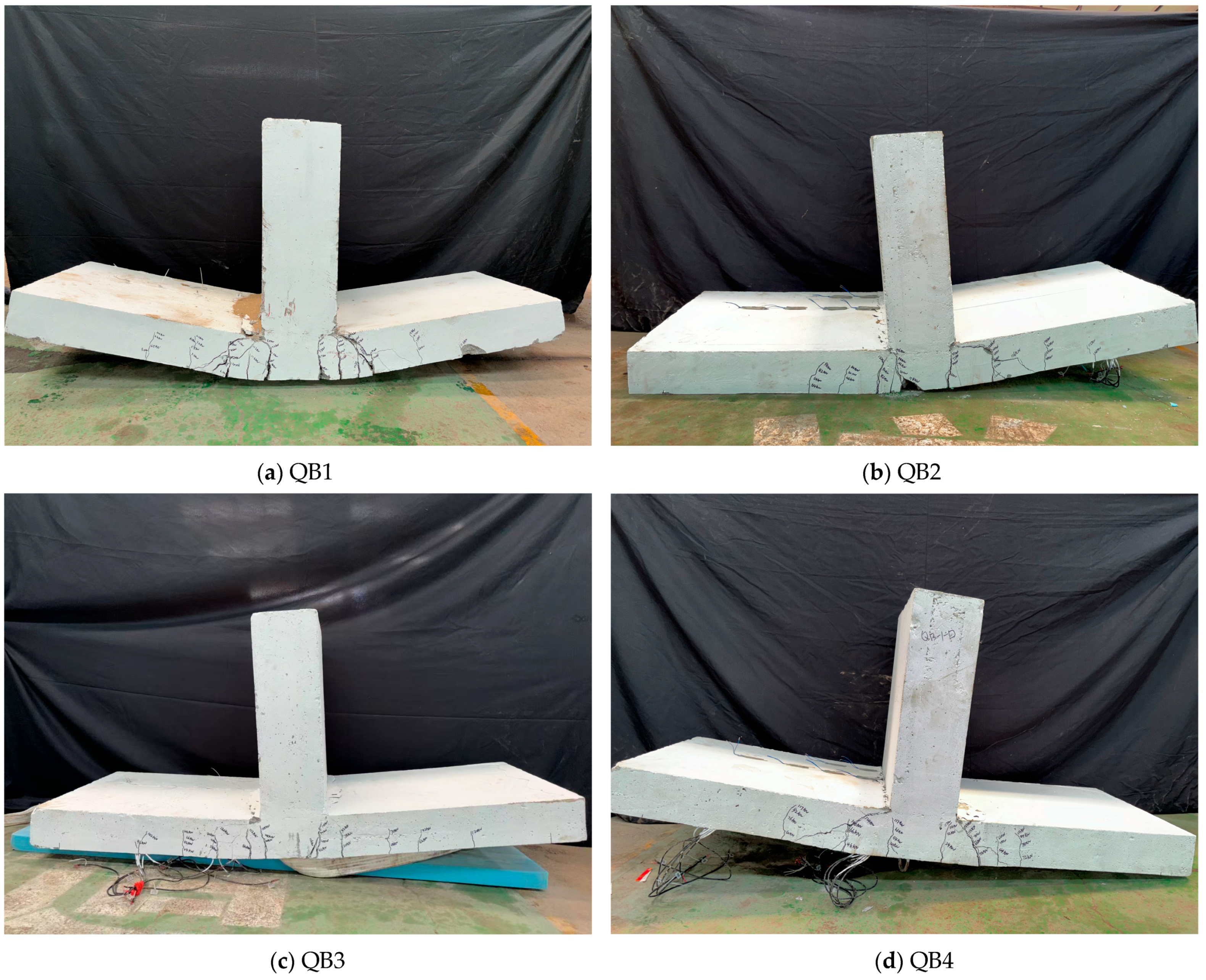
3.1. Experimental Observations
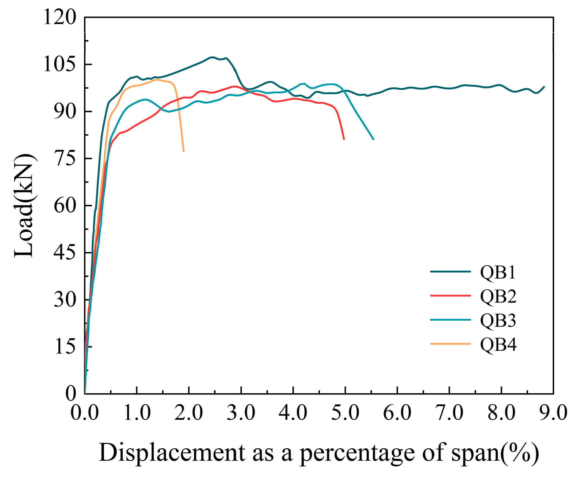
3.2. Load–Displacement Curves
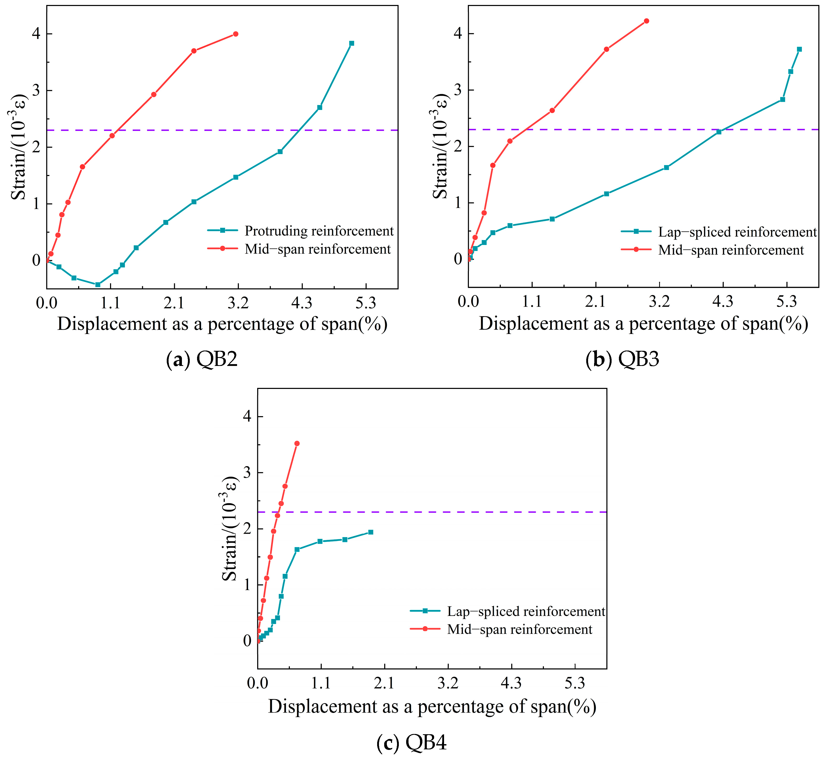
3.3. Reinforcement Strain Results
4. Discussion of the Design Method
4.1. Flexural Load-Carrying Capacity Calculation
4.2. Flexural Stiffness Calculation
5. Finite Element Model (FEM)
5.1. Model Parameters
5.2. Material Properties
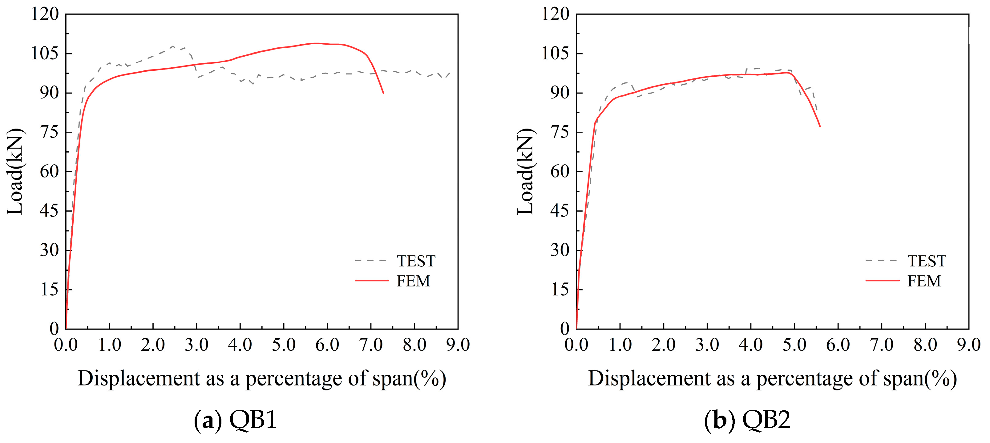
5.3. Finite Element Validation
5.4. Parametric Analysis and Design Recommendations
6. Discussion
7. Conclusions
Author Contributions
Funding
Data Availability Statement
Conflicts of Interest
References
- Masood, R. Modelling Prefabricated Construction Safety. Appl. Sci. 2024, 14, 1629. [Google Scholar] [CrossRef]
- Navaratnam, S.; Satheeskumar, A.; Zhang, G.M.; Nguyen, K.; Venkatesan, S.; Poologanathan, K. The challenges confronting the growth of sustainable prefabricated building construction in Australia: Construction industry views. J. Build. Eng. 2022, 48, 103935. [Google Scholar] [CrossRef]
- Bao, Y.X.; Xiang, C.Y. Integration of BIPV technology with modular prefabricated building—A review. J. Build. Eng. 2025, 102, 111940. [Google Scholar] [CrossRef]
- Parracho, D.F.R.; El-Din, M.N.; Esmaeili, I.; Freitas, S.S.; Rodrigues, L.; Martins, J.P.; Corvacho, H.; Delgado, J.; Guimaraes, A.S. Modular Construction in the Digital Age: A Systematic Review on Smart and Sustainable Innovations. Buildings 2025, 15, 765. [Google Scholar] [CrossRef]
- Tumminia, G.; Guarino, F.; Longo, S.; Ferraro, M.; Cellura, M.; Antonucci, V. Life cycle energy performances and environmental impacts of a prefabricated building module. Renew. Sustain. Energy Rev. 2018, 92, 272–283. [Google Scholar] [CrossRef]
- Wu, X.C.; Han, J.Y.; Cui, H.L.; Li, T.L.; Bai, X.Y.; He, Y.L.; Liu, N. A Comparative Review of Recent Research Progress in Prefabricated Buildings in China and Other Countries. Buildings 2024, 14, 1062. [Google Scholar] [CrossRef]
- Wang, G.S.; Liu, J.H.; Zhang, Y.B.; Zhang, Z.Y.; Tao, J.W.; Wu, D.Y. Theoretical and Experimental Study on the Stress State of Joints in Two-Way Composite Slabs. Buildings 2024, 14, 3374. [Google Scholar] [CrossRef]
- Huang, K.L.; Wang, X.J.; Wang, F.J.; Zhang, T.R. Mechanical Properties and Loading Simulation of Unidirectional Laminated Slabs Made from Recycled Concrete with Manufactured Sand. Buildings 2024, 14, 674. [Google Scholar] [CrossRef]
- Chen, Y.; Shi, H.R.; Wang, C.L.; Wu, J.; Liao, Z.Q. Flexural mechanism and design method of novel precast concrete slabs with crossed bent-up rebar. J. Build. Eng. 2022, 50, 104216. [Google Scholar] [CrossRef]
- Abdullah, M.D.; Mosheer, K.A.M. Effect of Stirrups on the Behavior of Semi-Precast Concrete Slabs. Civ. Eng. J. 2022, 8, 1653–1664. [Google Scholar] [CrossRef]
- Deng, B.Y.; Tan, D.; Li, L.Z.; Zhang, Z.; Cai, Z.W.; Yu, K.Q. Flexural behavior of precast ultra-lightweight ECC-concrete composite slab with lattice girders. Eng. Struct. 2023, 279, 115553. [Google Scholar] [CrossRef]
- Lam, S.S.E.; Wong, V.; Lee, R.S.M. Bonding assessment of semi-precast slabs subjected to flexural load and differential shrinkage. Eng. Struct. 2019, 187, 25–33. [Google Scholar] [CrossRef]
- Fu, Y.Q.; Fan, G.L.; Tao, L.; Yang, Y.J.; Wang, J.C. Seismic behavior of prefabricated steel reinforced concrete shear walls with new type connection mode. Structures 2022, 37, 483–503. [Google Scholar] [CrossRef]
- Qiao, Q.Y.; Peng, J.; Cao, W.L.; Dong, H.Y. Seismic performance of innovative prefabricated reinforced recycled concrete shear walls. Structures 2023, 58, 105617. [Google Scholar] [CrossRef]
- Wang, D.H.; Liu, X.D.; Wang, S.; Li, S.S. Research Status on Bonding Behavior of Prefabricated Concrete Shear Wall. In IOP Conference Series: Materials Science and Engineering; IOP Publishing: Bristol, UK, 2018; Volume 322. [Google Scholar] [CrossRef]
- Ximei, Z.; Jiayu, Y.; Can, C. Seismic performance and flexible connection optimization of prefabricated integrated short-leg shear wall filled with ceramsite concrete. Constr. Build. Mater. 2021, 311, 125224. [Google Scholar] [CrossRef]
- Gao, Y.F.; Yang, Z.; Chen, L.; Cheng, S.Z.; Zhang, Z.S. The Anchorage Performance and Mechanism of Prefabricated Concrete Shear Walls with Closed-Loop Rebar. Buildings 2025, 15, 131. [Google Scholar] [CrossRef]
- Gong, C.; Huang, Z.F.; Liang, Z.H.; Hou, Z.X.; Zhang, S.M. Seismic performance of assembled concrete shear wall with vertical shell and multi-loop connections. Structures 2025, 73, 108492. [Google Scholar] [CrossRef]
- Li, Z.; Tian, D.; Lu, J.; Tian, C.; Zhao, Y.; Zeng, Q.; Teng, J. Experimental study on seismic behavior of fully assembled L-shaped section double-sided composite shear wall. J. Build. Struct. 2025, 46, 61–72. [Google Scholar]
- Ma, W.; Xu, K.; Cheng, B.Q.; Zhang, Y.G.; Chen, R.; Chen, D. Experimental study on the seismic behavior of a new single-faced superposed shear wall with the concealed column. Structures 2021, 33, 4446–4460. [Google Scholar] [CrossRef]
- Xue, W.; Hu, X. State of the art of studies on precast concrete shear wall structures. J. Build. Struct. 2019, 40, 44–55. (In Chinese) [Google Scholar]
- Soleimani-Abiat, M.; Banan, M.R. Seismic behavior of RC building by considering a model for shear wall-floor slab connections. Comput. Concr. 2015, 16, 381–397. [Google Scholar] [CrossRef]
- Kim, J.H.; Choi, S.H.; Hwang, J.H.; Jeong, H.; Han, S.J.; Kim, K.S. Experimental study on lateral behavior of post-tensioned precast beam-column joints. Structures 2021, 33, 841–854. [Google Scholar] [CrossRef]
- Yang, T.; Chen, W.Q.; Han, Z.Q. Experimental Investigation of Progressive Collapse of Prestressed Concrete Frames after the Loss of Middle Column. Adv. Civ. Eng. 2020, 2020, 8219712. [Google Scholar] [CrossRef]
- Husain, M.; Yu, J.; Osman, B.H.; Ji, J. Progressive collapse resistance of post-tensioned concrete beam-column assemblies under a middle column removal scenario. J. Build. Eng. 2021, 34, 101945. [Google Scholar] [CrossRef]
- Zhang, W.S. Progressive collapse of post-tensioned subframes following the removal of an interior column. Eng. Struct. 2022, 254, 113841. [Google Scholar] [CrossRef]
- Li, Z.X.; Liu, H.K.; Shi, Y.C.; Ding, Y.; Zhao, B. Experimental investigation on progressive collapse performance of prestressed precast concrete frames with dry joints. Eng. Struct. 2021, 246, 113071. [Google Scholar] [CrossRef]
- Eom, T.S.; Lee, S.J.; Jo, K.W.; Kim, M.J.; Lee, S.H.; Hwang, H.J. Experimental and analytical investigation of bracket moment connection for precast concrete beam-to-composite column joints. J. Build. Eng. 2024, 96, 110593. [Google Scholar] [CrossRef]
- Wu, Z.L.; Lu, X.L.; Bao, H.Y.; Li, L.Z.; Lu, Z.D. Experimental response of semi-rigid reinforced concrete beam-column joints with bolted angle dissipating connections. J. Build. Eng. 2024, 90, 109345. [Google Scholar] [CrossRef]
- Baran, E.; Mahamid, M.; Baran, M.; Kurtoglu, M.; Torra-Bilal, I. Performance of a moment resisting beam-column connection for precast concrete construction. Eng. Struct. 2021, 246, 113005. [Google Scholar] [CrossRef]
- Zhu, G.M.; Tan, K.H. Cyclic performance of precast steel beam-to-CECFST column exterior sub-assemblages with dry connections: Experimental studies and mechanism analyses. Eng. Struct. 2024, 315, 118410. [Google Scholar] [CrossRef]
- Salim, S.R.; Sahib, M.M.M. Experimental study on a new connection system for shear wall and slab joint. Int. J. Struct. Eng. 2022, 12, 405–420. [Google Scholar] [CrossRef]
- Zenunovic, D.; Folic, R. Models for behaviour analysis of monolithic wall and precast or monolithic floor slab connections. Eng. Struct. 2012, 40, 466–478. [Google Scholar] [CrossRef]
- Ding, R.; Sun, Y.T.; Nie, X.; Chen, D.Q. Experimental study on seismic behaviour of an unreinforced precast wall-slab structure based on UHPC sandwich panels. J. Build. Eng. 2023, 68, 106197. [Google Scholar] [CrossRef]
- Chalot, A.; Roy, N.; Michel, L.; Ferrier, E. Mechanical behavior of a full-scale RC wall-slab connection reinforced with frp under cyclic loading. Eng. Struct. 2021, 239, 112146. [Google Scholar] [CrossRef]
- Jiang, Y.X.; Chen, H.B.; Nie, X.; Tao, M.X. Experimental study on bond and anchorage of steel bars in precast concrete structures with new-to-old concrete interface. Eng. Struct. 2021, 247, 113086. [Google Scholar] [CrossRef]
- Yang, Y.; Jiang, X.; Nie, X.; Wang, S.; Wu, B. Experimental study on mechanical behavior of concrete composite slab with rabbets. J. Build. Struct. 2023, 44, 142–151. (In Chinese) [Google Scholar]
- Nie, X.; Zhuang, L.; Li, Y.; Yang, Y. Experimental study on the mechanical properties of two-way concrete composite slab with notches. J. Southeast Univ. Nat. Sci. Ed. 2024, 54, 251–259. (In Chinese) [Google Scholar] [CrossRef]
- Huang, D.; Nie, X.; Fan, J.S.; Ding, R. Experimental study on longitudinal shear behavior of prefabricated steel-concrete composite beams with notched connections. Eng. Struct. 2024, 300, 117151. [Google Scholar] [CrossRef]
- GB 50010—2010; Code for Design of Concrete Structures. China Architecture & Building Press: Beijing, China, 2015. (In Chinese)
- JGJ1-2014; Technical Specification for Prefabricated Concrete Structures. China Architecture & Building Press: Beijing, China, 2014. (In Chinese)
- DG/TJ08-2071-2010; Code for Design of Assembled Monolithic Concrete Buildings. Shanghai Building Materials Industry Market Management Station: Shanghai, China, 2010. (In Chinese)
- Chen, L.H.; Feng, J.D.; Xue, Y.T.; Liang, C.W. Seismic behavior of an innovative prefabricated steel-concrete composite beam-column joint. J. Build. Eng. 2023, 76, 107211. [Google Scholar] [CrossRef]
- Seok, S.; Haikal, G.; Ramirez, J.A.; Lowes, L.N.; Lim, J. Finite element simulation of bond-zone behavior of pullout test of reinforcement embedded in concrete using concrete damage-plasticity model 2 (CDPM2). Eng. Struct. 2020, 221, 110984. [Google Scholar] [CrossRef]
- Bilal, K.A.; Mahamid, M.; Hariri-Ardebili, M.A.; Tort, C.; Ford, T. Parameter Selection for Concrete Constitutive Models in Finite Element Analysis of Composite Columns. Buildings 2023, 13, 1759. [Google Scholar] [CrossRef]
- Nie, J.; Wang, Y. Comparison study of constitutive model of concrete in abaqus for static analysis of structures. Eng. Mech. 2013, 30, 59. (In Chinese) [Google Scholar]
- Zhang, J.; Wang, Q.; Hu, S.; Wang, C. Parameters Verification of Concrete Damaged Plastic Model of ABAQUS. Build. Struct. 2008, 38, 127–130. (In Chinese) [Google Scholar]
- Wang, Y.S.; Lin, R.S.; Wang, X.Y. Insights on solid CO2 mixing method for hybrid alkaline cement (HAC): Performance, sustainability, and experimental system improvement. Cem. Concr. Compos. 2025, 161, 106096. [Google Scholar] [CrossRef]
- Wang, Y.S.; Meng, L.Y.; Chen, L.; Wang, X.Y. An innovative strategy for CO2 conversion and utilization: Semi-wet carbonation pretreatment of wollastonite to prepare carbon-fixing products and produce LC3. Cem. Concr. Compos. 2025, 160, 106050. [Google Scholar] [CrossRef]
- Huang, H.; Wang, T.; Kolosz, B.; Andresen, J.; Garcia, S.; Fang, M.X.; Maroto-Valer, M.M. Life-cycle assessment of emerging CO2 mineral carbonation-cured concrete blocks: Comparative analysis of CO2 reduction potential and optimization of environmental impacts. J. Clean. Prod. 2019, 241, 118359. [Google Scholar] [CrossRef]
- Huang, H.; Guo, R.N.; Wang, T.; Hu, X.T.; Garcia, S.; Fang, M.X.; Luo, Z.Y.; Maroto-Valer, M.M. Carbonation curing for wollastonite-Portland cementitious materials: CO2 sequestration potential and feasibility assessment. J. Clean. Prod. 2019, 211, 830–841. [Google Scholar] [CrossRef]


| Connection Method | Performance | Constructability | Cost Implications |
|---|---|---|---|
| Proposed slotted system | High ductility and load capacity | Simplified formwork; reduced labor | Cost savings through reduced manual labor |
| Protruding rebar | Moderate performance | Complex formwork; high labor requirement | Higher due to labor intensity |
| Mechanical splice systems | High strength and reliability | Requires precise installation | Higher material and labor costs |
| Grouted sleeve connections | High strength and good ductility | Requires precise installation | Moderate due to material and labor cost |
| Specimen ID | Slab Configuration | Longitudinal Reinforcement in Precast Slab | Lap-Spliced Reinforcement | Slot Dimensions (Depth × Width × Length) |
|---|---|---|---|---|
| Layout/Length | ||||
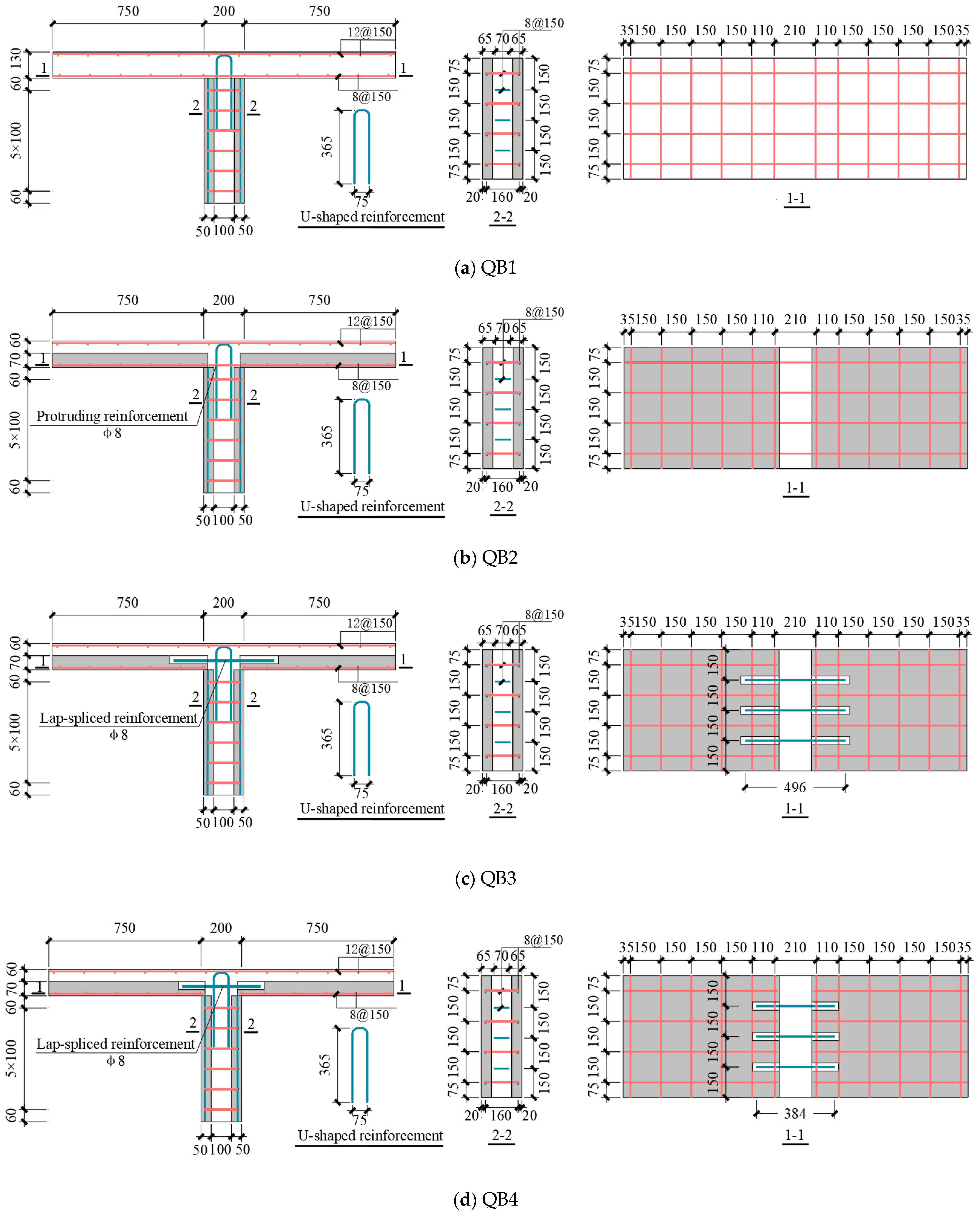
| QB1 | Fully cast-in-place slab | Φ8@150 | / | / |
| QB2 | Precast slab with protruding reinforcement | Φ8@150 | / | / |
| QB3 | Slotted composite slab | Φ8@150 | Φ8@150/12d | 40 × 40 × 190 |
| QB4 | Slotted composite slab | Φ8@150 | Φ12@150/9.3d | 40 × 40 × 132 |
| Concrete Type | fc (MPa) | σ/CV | (Mpa) | Ec (Mpa) | ||
|---|---|---|---|---|---|---|
| 1# | 2# | 3# | ||||
| Precast Wall | 42.1 | 43.9 | 47.5 | 2.24/5.04% | 44.5 | 35.6 |
| Precast Slab | 46.0 | 48.3 | 49.1 | 1.31/2.75% | 47.8 | 32.2 |
| Cast-in-Place Topping Layer | 39.3 | 45.6 | 44.7 | 2.78/6.44% | 43.2 | 33.7 |
| D | fy (Mpa) | σ/CV | (Mpa) | fu (Mpa) | σ/CV | (Mpa) | Es (Mpa) | ||||
|---|---|---|---|---|---|---|---|---|---|---|---|
| 1# | 2# | 3# | 1# | 2# | 3# | ||||||
| 8 mm | 457.8 | 448.8 | 447.3 | 4.64/1.03% | 451.3 | 614.6 | 616.9 | 624.3 | 4.14/0.67% | 618.6 | 2.0E5 |
| 12 mm | 458.6 | 462.9 | 463.3 | 2.13/0.46% | 461.6 | 631.1 | 645.1 | 624.9 | 8.45/1.33% | 633.7 | 2.0E5 |
| Specimen ID | Mcr (kNm) | My (kNm) | θcr (%) | dy (mm) | Mu (kN) | df (mm) | μ | Bcr (kNm2) | By (kNm2) |
|---|---|---|---|---|---|---|---|---|---|
| QB1 | 5.2 | 21.9 | 0.103 | 3.8 | 108.4 | / | / | 3060.5 | 1229.9 |
| QB2 | 3.9 | 24.3 | 0.086 | 6.3 | 97.1 | 74.6 | 11.8 | 2560.7 | 1146.1 |
| QB3 | 2.6 | 24.9 | 0.058 | 6.8 | 98.6 | 83.1 | 12.2 | 2520.1 | 1124.4 |
| QB4 | 2.6 | 23.3 | 0.057 | 4.5 | 99.7 | 28.5 | 6.3 | 2543.6 | 1139.3 |
| Specimen ID | Pe (kN) | Pt (kN) | Pe/Pt |
|---|---|---|---|
| QB1 | 108.4 | 103.4 | 0.96 |
| QB2 | 97.1 | 96.3 | 0.99 |
| QB3 | 98.6 | 96.3 | 0.98 |
| QB4 | 99.7 | 96.3 | 0.97 |
| Specimen ID | (kNm2) | (kNm2) | (kNm2) | (kNm2) | (kNm2) | |||
|---|---|---|---|---|---|---|---|---|
| QB1 | 3060.5 | 3277.5 | 0.93 | 1229.9 | 1021.5 | 1.20 | 986.0 | 1.24 |
| QB2 | 2560.7 | 0.78 | 1146.1 | 1.12 | 1.16 | |||
| QB3 | 2520.1 | 0.77 | 1124.4 | 1.10 | 1.14 | |||
| QB4 | 2543.6 | 0.78 | 1139.3 | 1.12 | 1.16 |
| μ | Pressure–Overclosure | Stiffness (MPa/mm) | Peak Stress (mm) | ||||
|---|---|---|---|---|---|---|---|
| Knn | KSS | Ktt | |||||
| 0.6 | “Hard” Contact | 1 × 10⁵ | 10 | 10 | 1.6 | 0.8 | 0.8 |
| Eccentricity | Dilation Angle | fbo/fco | K | Viscosity Parameter | |
|---|---|---|---|---|---|
| 0.1 | 30 | 1.16 | 0.667 | 0.0005 | 0.3 |
| Key Parameter | Slot Spacing | Diameter of the Lap-Spliced Reinforcement | Anchorage Length of the Lap-Spliced Reinforcement |
|---|---|---|---|
| Recommended Value | 120 mm | 10 mm | 21d |
Disclaimer/Publisher’s Note: The statements, opinions and data contained in all publications are solely those of the individual author(s) and contributor(s) and not of MDPI and/or the editor(s). MDPI and/or the editor(s) disclaim responsibility for any injury to people or property resulting from any ideas, methods, instructions or products referred to in the content. |
© 2025 by the authors. Licensee MDPI, Basel, Switzerland. This article is an open access article distributed under the terms and conditions of the Creative Commons Attribution (CC BY) license (https://creativecommons.org/licenses/by/4.0/).
Share and Cite
Shang, X.; Zheng, M.; Guo, Y.; Zhuang, L.; Liang, H. Experimental Investigation on Static Performance of Novel Precast Concrete Composite Slab–Composite Shear Wall Connections. Buildings 2025, 15, 1935. https://doi.org/10.3390/buildings15111935
Shang X, Zheng M, Guo Y, Zhuang L, Liang H. Experimental Investigation on Static Performance of Novel Precast Concrete Composite Slab–Composite Shear Wall Connections. Buildings. 2025; 15(11):1935. https://doi.org/10.3390/buildings15111935
Chicago/Turabian StyleShang, Xiaozhen, Ming Zheng, Yutao Guo, Liangdong Zhuang, and Huqing Liang. 2025. "Experimental Investigation on Static Performance of Novel Precast Concrete Composite Slab–Composite Shear Wall Connections" Buildings 15, no. 11: 1935. https://doi.org/10.3390/buildings15111935
APA StyleShang, X., Zheng, M., Guo, Y., Zhuang, L., & Liang, H. (2025). Experimental Investigation on Static Performance of Novel Precast Concrete Composite Slab–Composite Shear Wall Connections. Buildings, 15(11), 1935. https://doi.org/10.3390/buildings15111935