Abstract
Buildings of historic neighborhoods of Santiago de Chile are protected by a coating system composed of different layers of earth-based mortars, as part of a building culture that has been neglected and forgotten since the introduction of industrialized materials but still exists in many buildings. This study presents preliminary results from ongoing research that explores the hygroscopic capacity of this vernacular coating system and the impact of incorporating recent finishing layers into traditional construction practices. The investigation focuses on identifying materials and techniques typical of traditional Chilean coatings, highlighting their role in enhancing the durability of historic buildings, improving user comfort, and promoting environmental sustainability. It contributes to the conservation of historic buildings and their reuse, as well as to the health of its inhabitants, due to its contribution to hygrometric regulation. This article focuses on this last purpose, through the identification and characterization of the coating system and its finishing layer materials, and a comparative sorption/desorption test of four case studies with these vernacular coatings. This study began with the sample extraction in situ, followed by its observation and cataloguing. Stratigraphic and stereo microscope analysis of the finishing layers were carried out to identify them. The characterization of the finishing materials was performed using FTIR-ATR and SEM-EDX tests. The sorption/desorption test was performed with a set of original complete samples of the four case studies. Subsequently, another set was prepared with the removal of the finishing layers in order to compare their influence on the hygroscopicity of the coating systems. The results elucidate the variety of materials employed on the finishing layer of these coatings, which are often superimposed, revealing renovations and reparations over time. The influence of these finishing materials on sorption properties of the coating system (the scratch and base coats) is exposed by comparing the samples with and without them.
1. Introduction
The city of Santiago, in Chile, presents a significant number of earthen buildings, some from colonial times, including the oldest one, the church and convent of San Francisco, from the 16th century, which is still inhabited [1]. After the first light timber structures settlements, adobe masonry was the most massive technique employed by the Spanish from the 16th century onwards. This technique allowed a more permanent and defensive form of construction in the colonization process [2]. Along with adobe, earthen-filled timber frame walls were part of the traditional constructive techniques of Santiago. As interior partitions or external envelope walls, they can be divided into three types, named locally as quincha, adobe en pandereta, and adobillo, the first one existing since pre-Hispanic times, and the last two from the Republic period in the 19th century [3,4].
Traditional coatings are often multilayer composed, and are renewed cyclically, especially the finishing layer [5,6,7]. As used in other traditional practices, a three-layer system responds to different functions in obtaining a finishing surface [8]. In the case of the Chilean vernacular coatings, different finishings are used.
From field work, it has been observed that different traditional construction wall systems, whether made of earth or fired brick, share the same coating system. The general coating system present in the historic neighborhoods of Santiago consistently presents two distinct earthen layers: one with fibers in contact with the substrate, covered by another layer without fibers, sandier, with different finishing materials applied on top of it. The first, rough, scratch earthen mortar with vegetable fiber layer usually has roughly cut wheat straw. This layer is used to cover the imperfections and to adjust the level of the wall. The second earth and sand layer, a base or float coat, helps to flatten the first layer. It is characterized for being very stable, although friable, and without significant cracking. The first layer, on the contrary, could have small cracks resulting from the mortar shrinkage, even if stabilized with large vegetable fibers. In the interior surfaces of walls, the finishing systems can vary from lime- or gypsum-based thin mortars to limewash, water-based or synthetic paints, and wallpaper. The exterior finishings are more restricted, as a result of exposure to atmospheric conditions [9]. These traditional earthen building coatings can be found with the same section layering system in other regions, as in the Limary Valley [10].
The thickness of the first layer, the scratch coat, can vary between 10 and 45 mm, with an average of 24.5 mm, while for the second layer (for simplicity called base coat) varies between 5 and 20 mm, according to 11 samples taken from five buildings in the center of Santiago, as shown in Table A1 [11]. These samples show different finishings, the last ones generally installed in recent times. Starting from the premise that earthen materials make an important contribution to moisture passive regulation of built environments [12], and that many recent finishing layers are mainly made of synthetic or impermeable materials, a question that emerges is whether these solutions are compatible with the original fabric of the buildings, made with earth, wood, and fired bricks [13,14,15]. Due to the lack of open pore structure, these materials may reduce and block the capacity to balance out fluctuations in the relative humidity of an ambience with earthen materials [12,16]. This effect is presumably the cause of the degradation of the coating system, as well as of pathologies in the building walls.
This paper intends to delve deeper into the relation between the finishing layers and the hygroscopic behavior of these coating systems. Particular attention is given to the understanding of the alterations that the finishing layers could exert on the earth coating system, and therefore the habitability of buildings.
2. Materials and Methods
2.1. Sampled Coatings from Vernacular Buildings in Santiago
This study focuses on the analysis of case studies of traditional building coating in historical neighborhoods of Santiago (Chile), constructed between the late 19th century and the first half of the 20th century, with finishings from different periods. For this purpose, a new sampling campaign was carried out in two buildings in the center of Santiago, resulting in four new cases studied. The samples extracted in the new campaign are part of a broader study. Therefore, the already established nomenclature system will continue to be used. The nomenclature is divided into three parts: the first refers to the historic neighborhood from which the samples have been extracted (SC-Santiago Centro; MS-Matta Sur); the second part refers to the name of the specific historical building studied (C10-Casa de los 10; JJVV-Junta de Vecinos); and the last to the specific sample that has been obtained (01, 02, 03, 04).
The specimens studied in this work were extracted in two different historic neighborhoods (SC, MS) and from one building in each of them (C10, JJVV, correspondingly), in the first case with three samples (SCC10_02, SCC10_03, SCC10_04), and the second with one (MSJJVV_02).
The MSJJVV_02 case study samples were extracted from an interior adobe-filled timber frame wall from a single-family house, built in 1935. The samples SCC10_02, SCC10_03A, and SCC10_04 belong to a building constructed in 1840, although the first two samples come from an outbuilding placed in the backyard of the house which could be of a later date. This outbuilding is an adobe structure, and the SCC10_02 samples were extracted from the exterior coating (its render) of the entrance wall of this outbuilding, while the SCC10_3A represents the internal coating (its plaster) of the same wall. As for the SCC10_04, the wall sample set was extracted from the internal surface of the adobe façade wall of the main building, facing an important street in the center of Santiago. Regarding the possible date of production of this plaster, there are statements from the last owners that have memories of the room with the naked adobe wall, which would only have been coated in the 1970s.
All samples were extracted to obtain a complete and intact section starting from the supporting wall to the finishing layer (examples in Figure 1 and characterization in Table 1). To achieve this, it was essential to use a multipurpose electric tool which cuts surfaces through the vibration of a metal blade. The lines defining the samples on the wall surface were traced and cut with the multipurpose power tool and a grinder machine. Then, the surrounding surface was removed, allowing the metal blade to be placed in this space, parallel to the wall, detaching the samples in a slow and controlled movement. The extraction location on the wall was chosen by selecting the surfaces in the best conservation conditions and ease of extraction. In this sense, the samples in the SCC10_02 case study were extracted from a higher level, close to the roof eaves, where the sample was less washed by rain. In the case of MSJJVV_02, samples were extracted above the newly installed false ceiling where older wall finishes were present. For SCC10_03 and SCC10_04, the samples were extracted at a height of 2.0 m and 1.2 m from ground level, respectively. The samples were wrapped in plastic packaging suitable for transport and stored in cardboard boxes.
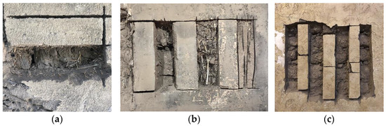
Figure 1.
Images of the wall coating sampling extraction process: (a) SCC10_02, (b) SCC10_03A, (c) SCC10_04.

Table 1.
Average thickness of the two earthen layers of the sampled coatings, identification of the substrate, and the internal or external location of the coatings.
The samples extracted present the aforementioned system of two earthen layers with different finishings as shown in previous campaigns [9,11], and the field work observations. The average minimum and maximum thicknesses of the thick coating layer, with fibers, of the four case studies are 14.7 mm and 21.9 mm, respectively. As would be expected by previous campaigns, the second layer has lower thicknesses, with the averages of the set of samples from each case study varying between 10.0 mm and 11.4 mm.
Each sample presents various finishings, which would have been applied at different stages of the building’s use but not documented. These were revealed through a preliminary stratigraphic work to identify the diversity of superimposed layers in the finishing coat and to recollect material for the characterization tests of these finishings (Figure 2). This first identification was complemented with optical microscopy, identifying layers that might have not been well represented in the stratigraphy.
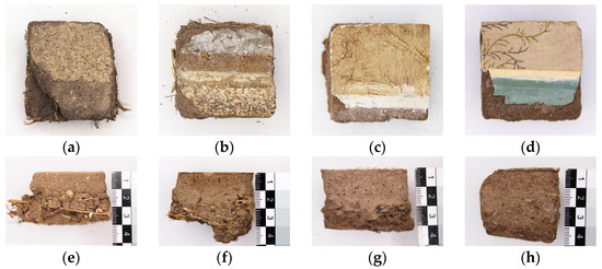
Figure 2.
Stratigraphy of the finishings (last finish layer on the top) of specimens: (a) SCC10_02; (b) SCC10_03A; (c) SCC10_04; (d) MSJJVV_02. Lateral views of the earthen layers (earth and sand on the top, earth and fibers on the bottom) of specimens: (e) SCC10_02; (f) SCC10_03A; (g) SCC10_04; (h) MSJJVV_02.
2.2. Material Testing of Finishing Layers
2.2.1. Optical Microscopy and Microchemical Study
All samples were analyzed with a stereo microscope MOTIC SMZ-168-TP (Kowloon, Hong Kong) and photographed using an Euromex Microscope Camera CMEX-10 PRO USB 3.0 (Duiven, The Netherlands) to verify the set of finishing layers, which are often difficult to identify when visually observing the samples. The number of layers and their nature were observed. Complementarily, microchemical testing was performed in order to clarify or confirm the results on the nature of the materials. These procedures can detect organic or inorganic compounds through the identification of characteristic groups and are applied using direct or indirect tests [17,18]. In particular, the different layers were directly tested with two solvents, water and acetone, or a 10% v/v solution of hydrochloric acid, using one drop for each test.
Subsequently, since some samples suggested the presence of vinylic additives, a simple qualitative indirect approach was designed to find them in complex matrices thanks to a 2-step reaction which leads to the formation of a compound readily detectable. In detail, for selected layers, ~10 mg was tested by adding it to a 10% m/v solution of sodium hydroxide (NaOH) in absolute ethanol, followed by heating at 50–60 °C for 10–15 min. If Polyvinyl Acetate (PVAc) was present, hydrolysis occurred, producing polyvinyl alcohol and sodium acetate [19]. Due to this saponification reaction, which occurs rapidly thanks to the mild heating applied, partial or complete dissolution of the sample was observed. In order to confirm the presence of acetate ions, the solution was then acidified with a 10% v/v solution of sulfuric acid (H₂SO₄), and, in the case of a positive test, the characteristic vinegar-like odor of acetic acid was detected. The use of this relatively concentrated acid solution ensures the detection of vinylic additives in the order of µg of material with the use of single drops.
To further understand the physicochemical nature of the finishing materials, the samples were then fully characterized by means of scanning electron microscopy combined with an energy dispersive X-ray Spectrometer (SEM-EDX) and attenuated total reflectance Fourier transform infrared spectroscopy (FTIR-ATR).
2.2.2. SEM and FTIR-ATR Analysis
The surface characterization of the finishing layers was performed by means of scanning electron microscopy (SEM) with a FEI Quanta 250 (Thermo Fisher Scientific, Bleiswijk, The Netherlands) equipped with an energy dispersion spectrometer probe (EDX) (XTE 325/D8395). The SEM-EDX analysis was performed with an electron tension of 20.0 kV and under low vacuum. The EDX probe was used to perform linear analysis and 2D mappings to determine the elementary composition of the samples. For this analysis, the samples were prepared by selecting fractions of the finishing layers.
Further analysis of the main functional groups of the finishing layers was performed by attenuated total reflectance Fourier transform infrared spectroscopy (FTIR-ATR). The measurements were acquired using a Perkin-Elmer spectrometer (Perkin-Elmer, Shelton, CT, USA) equipped with a “UATR two” ATR module. Spectra were recorded at room temperature in the range 400-4000 cm−1, reported in transmittance%, and the identification and interpretation of the functional groups were performed using OMNICTM Software, version 7.0.
2.3. Sorption/Desorption Tests
The sorption/desorption test aims to determine the influence of the finishing layers on the hygroscopic properties of the complete coating system, and was performed based on the DIN 18947 [20], the only existing standard for earthen plaster characterization, and adaptations previously defined [21]. According to this norm, the samples should have a surface of 1000 cm2, with a thickness of 15 mm; that was not the case in this study. However, other studies [12] have used smaller samples. As mentioned before, the specimens used in this test come from in situ extracted multilayer samples of vernacular earthen building’s wall coatings, with variable thicknesses and surface areas. Six specimens were selected for each one of the four case studies, so that in the hygroscopic test, each case study is represented with three specimens with and without the finishing system.
As established by the aforementioned German norm, the samples were stabilized at 50% relative humidity (RH) and 23 ± 5 °C in a climatic chamber ARALAB Fitoclima 700EDTU (Rio de Mouro, Portugal), presenting constant mass (variation lower than 0.02% in 24 h) before running the test. The climatic chamber was then set at 80% RH and 23 ± 5 °C. The sorption cycle was extended to 24 h, and a 24 h desorption cycle, set at 50% RH and 23 ± 5 °C, was also included. The precision balance used for the test had an accuracy of 0.01 g. The samples were weighted after ~1, 3, 6, 12, and 24 h for both the sorption and desorption cycles.
To prepare the specimens for the test, high waterproof adhesion aluminum tape (3M Scotch) was applied to the back and at the sides, overlapping by at least 1 cm, resulting in only the surface of each specimen remaining exposed. In the case of the specimens where the finishing was removed, the sandy earth layer remained exposed. When the edge was perfectly straight, this tape did not overlap the finishing surface unless the side did not adhere well to the tape. In this case, the tape overlapped a thin strip, the minimum required to hide imperfections in the finish along the edges. The most fragile sample for this procedure was SCC10_02, which easily disintegrated its finish on the edges of the surface plane, meaning there was no straight edge without imperfections in the finish. It should be noted that there were no samples of this case study in which the finishing surface was completely uniform, as it was degraded, with a very irregular micro-texture. As a result of this, in several of the aluminum strips that delimited the finishing surface, the tape did not adhere perfectly to the finish surface. The surface of the samples was photographed with a graphic scale and the surface area was measured in computer-aided design (CAD) software (AutoCad 2022) (Figure 3).
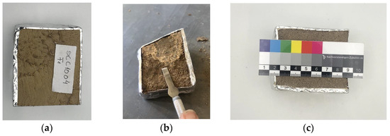
Figure 3.
Specimens for the hygroscopicity test: (a) SCC10_04 specimen with finishing; (b) SCC10_03A specimen with the finishing layer being removed; (c) MSJJVV_02 specimen without the finishing layer, with aluminum tape and scale for area measurement.
3. Results and Discussion
3.1. Material Characterization of Finishing Layers
3.1.1. Optical Microscopy and Microchemical Results
The microscopical analysis allowed the separation and identification of the different layers composing the superficial finishing systems of the specimens. As mentioned before, to distinguish the nature of the components of the finishings, the different identified layers were subjected to tests with hydrochloric acid, to detect the presence of calcium carbonate, and acetone, to detect the presence of organic components [22,23].
The results are hereby described following the sample order indicated in Figure 4.
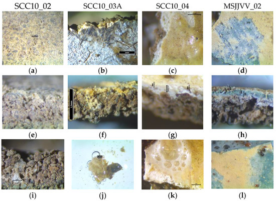
Figure 4.
Microscope photographs from the finishing layers of the coating samples studied. Each column corresponds to a sample. Surface view at the top: (a) SCC10_02; (b) SCC10_03A; (c) SCC10_04; (d) MSJJVV_02. Lateral view in the middle and bottom: (e) SCC10_02; (f) SCC10_03A; (g) SCC10_04; (h) MSJJVV_02; (i) SCC10_02 with presence of lime nodule. Reaction to hydrochloric acid solution at the bottom: (j) SCC10_03A; (k) SCC10_04; (l) MSJJVV_02.
SCC10_02: This case study presents only one finishing layer on top of the earthen base coat. This is a thin paint that penetrates the base coat, and which, due to wear caused by rain, shows some of the base earth mortar on the surface. This paint has an approximate thickness between 0.05 and 0.1 mm. Inside the earthen layer, some white nodules can be identified and correspond to a limewash paint. This, in some points, may have been sulphated because of the existing contamination in that area of the city (acid rain), converting the lime into gypsum. Some grey spots identified in microscopic observation point to the accumulation of contamination in this painting. In fact, EDX test displays signs of gypsum (calcium, sulfur, and oxygen) that could corroborate this chemical transformation of lime into gypsum. The painted finishing has ochre pigmentation, mixed with lime. The typical lime texture is observed, and isolated spots of pigmentation are identified. A preferred orientation is observed, and it is presumably due to the application of the paint.
SCC10_03A: This sample presents two layers on top of the base earthen mortar. The first layer is of yellowish color with fine aggregates (<0.065 mm), and with a lumpy texture, which is difficult to identify, but it reacts with hydrochloric acid, indicating the presence of calcium carbonate. Through microscopy observation, it presents a granular texture. On top of this, there is a light ochre layer, which does not react to hydrochloric acid. This is a very fine layer, reacting with acetone, indicating the presence of organic components. It could be identified as an acrylic or vinyl paint. All the samples are covered with a grey layer that dissolves in water and could be pollution residues, due to exposure in a contaminated zone of the city.
SCC10_04: The superficial yellowish layer of this sample is a film-forming layer which covers the entire surface. This would be a very thin layer of around 0.04 mm made of organic components, as it reacts to acetone. The white cover underneath is a lime coat, or a lime-based paste called pasta-muro [24]. In contact with the earthen base coat, it mixes with the aggregates of this mortar. The outer part of this lime layer has a more yellowish tone, which can be due to the carbonation of lime, or because it is contaminated by the color of the surface paint. The thickness of this layer is variable, with a maximum of 0.5 mm and the minimum observed being 0.17 mm, which is according to a thin paste rather than a paint layer, and explains the formation of the existing texture.
MSJJVV_02: The first layer on the top of the earthen base of this sample is a limewash mortar with irregular contact with the earthen one and an average thickness of 0.1 mm. It is covered by a very fine layer of blue pigmented limewash of 0.05 mm that finishes in a regular intense blue layer, indicating color fixing by carbonation. Accordingly, this phase reacts visibly with hydrochloric acid. The upper layer is a green paint that does not react either with acetone or hydrochloric acid, characterized by a regular thickness of 0.04 mm. Moving further up, another layer of blue pigment limewash paint is presented that also reacts to hydrochloric acid. The following layer is ochre, and the top of this layer is opaque, and it is easily scraped off, leaving an area of lighter, brighter color and greater hardness. This layer reacts with acetone, identifying the presence of organic components. In fact, this layer tested positive to the chemical test mentioned in Section 2.2.1, confirming the presence of vinylic additives. On the surface, there is a glued wallpaper that is about 0.1 mm thick.
3.1.2. SEM Analysis
The morphological study, carried out with electron microscopy, permitted a closer look at some details of the manufacture of the finishing layers. All the images obtained, divided for each sample, are reported in Figure 5.
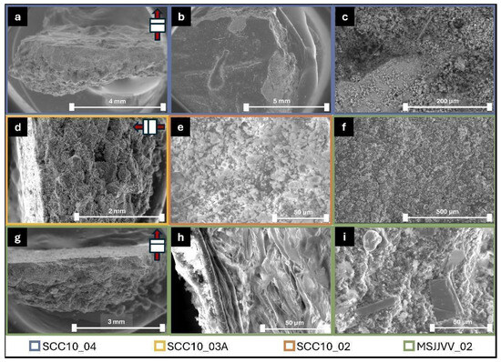
Figure 5.
SEM images showing the morphological features of the finishing layers of different samples, defined by border color: (a) fragment cross-section; (b) fragment surface; (c) surface zoom; (d) fragment cross-section; (e) surface crystalline deposition; (f) superficial paint covering; (g) fragment cross-section; (h) wallpaper; (i) aggregates in the gypsum layer. Note: In the cross-section pictures, an arrow shows the sample orientation with the end pointing along the surface.
The study of the sample’s morphology led to delineating some areas of interest, such as the sections of the fragments and the most superficial layers of the material. The first were studied with linear chemical depth profiles, while for the latter, the chemical nature of the species was studied with 2D-EDX mappings. The results are reported in Figure 6, Figure 7, Figure 8, Figure 9 and Figure 10, respectively.
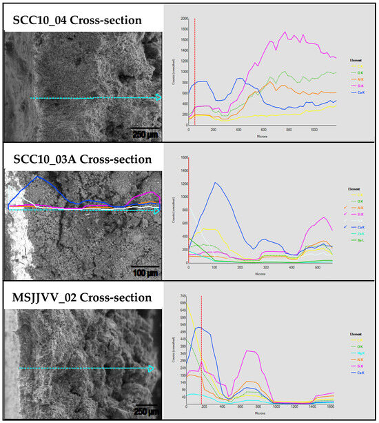
Figure 6.
Linear EDX measurements performed on cross-sections of the finishing layer fragments. The scheme shows the starting images with the measure line (left), and the resulting spectra (right). Note: The dash line indicates the direction of the results showed in the graphic.
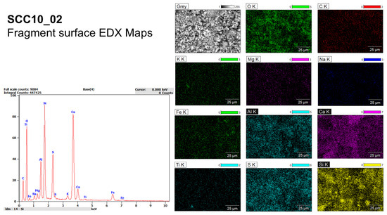
Figure 7.
Two-dimensional EDX mapping of the SCC10_02 surface. The cumulative spectrum (left) and the elemental maps (right) are reported.
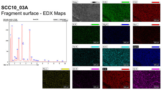
Figure 8.
Two-dimensional EDX mapping of the SCC10_03A surface. The cumulative spectrum (left) and the elemental maps (right) are reported.
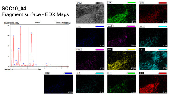
Figure 9.
Two-dimensional EDX mapping of SCC10_04 surface. The cumulative spectrum (left) and the elemental maps (right) are reported.
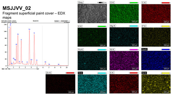
Figure 10.
Two-dimensional EDX mapping of MSJJVV_02 surface. The cumulative spectrum (left) and the elemental maps (right) are reported.
The linear measurements show a clear change from a first layer rich in calcium carbonate to a secondary layer of earthen base mortar, standing in the first 200 µm for SCC10_04 and SCC10_03A, and 400 µm for MSJJVV_02. This is underlined by the shift of high intensity values from Ca, O, and C to Si, Al, and O, which are characteristic of quartz and aluminosilicates. The result can be explained by considering that the surfaces of these materials have been flattened, during conservative treatment, with a commercial product called Pasta muro interior, which has a high composition of calcium carbonate (60–70%) [24].
The surface of the samples SCC10_04, SCC10_03A, and SCC10_02 show high signals of sulfur, calcium, and oxygen, which might be related to the presence of gypsum. Given the fact that the fragments come from building walls located in a very polluted part of the city, it is possible to attribute this presence to a sulfation of the calcium carbonate denoted in the linear measurements [25], and not the finishing initial composition.
The 2D-EDX mapping of the superficial paint finishing in sample MSJJVV_02 suggests the use of inorganic-based pigment in the preparation of the finishing layers. The presence of Ti high signals might indicate the use of rutile (TiO2), another frequent pigment used to obtain a white covering [26]. As in samples SCC10_04, SCC10_03A, and SCC10_02, the signals related to gypsum are responsible for a major part of the superficial composition of the samples.
3.1.3. FTIR-ATR Results
Further characterization of the finishing layer with FTIR-ATR added more insights related to fabrication methods. Figure 11 shows the infrared (IR) spectra of each material, along with the chemical attribution of the main functional groups and the IR spectra of their respective earth as a reference.
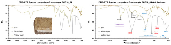
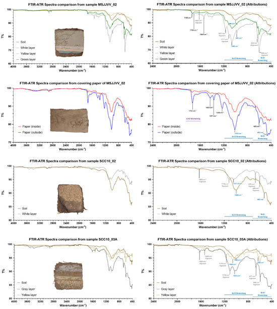
Figure 11.
ATR-FTIR spectra of the finishing layers (left) with the attributions of the main functional groups (right).
A series of white layers was analyzed in samples SCC10_04, SCC10_03A, SCC10 _02, and MSJJVV_02. While in the first sample the white layer is due only to the presence of calcium carbonate, in the other three samples it is associated mostly with the presence of gypsum. The positive test in microchemical testing with hydrochloric acid for sample SCC10_3A confirms that the presence of calcium carbonate in this layer is still possible. According to the results obtained from the EDX analysis on the respective samples, the presence of both compounds is possible and related to the use of these materials to obtain the finishing layers, as previously stated in the first microscopical observation and microchemical testing.
Other traces of gypsum were identified in patinas of different colors, such as the yellow and ochre patinas separated in sample SCC10_3A during the microscopical observation (analyzed simultaneously with the ATR module, “yellow layer” in Figure 11, sample SCC10_3A) or the green patina from sample MSJJVV_02. In the case of the brighter patinas, this supports the hypothesis of the use of a gypsum-based aqueous pigment to decorate the finishing layers. On the other hand, the deposition of gypsum is usually related to a rugosity increase [25]. This allows dust or smoke to further accumulate, presumably resulting in the grey patina observed.
The analysis of the wallpaper of sample MSJJVV_02 shows a spectrum where the signals of the paper are entirely covered by the signals of a polymeric material (indicated in black in the plot), an 80% match with polyvinyl acetate. This might be correlated to the vinyl resin that is part of the composition of the pasta muro interior [24]. Accordingly, traces of the same material are present in the spectrum of other samples, like the yellow layer of sample SCC10_04. The only other signals identified, on both sides of the paper, come from the respective earth layer, as indicated by the strong peak intensity related to symmetric and asymmetric SiO2 stretching.
3.2. Sorption/Desorption Results
Results of sorption/desorption tests of samples both with and without finishings are presented in Figure 12. All samples without a finishing layer present higher values on RH sorption, although SCC10_02’s case study presents only a minimal difference between the samples with and without finishing, while presenting the highest sorption. This might be attributed to the presence of a degraded limewash because, according to the previous morphological and chemical tests, the earthen base coat is partially exposed.
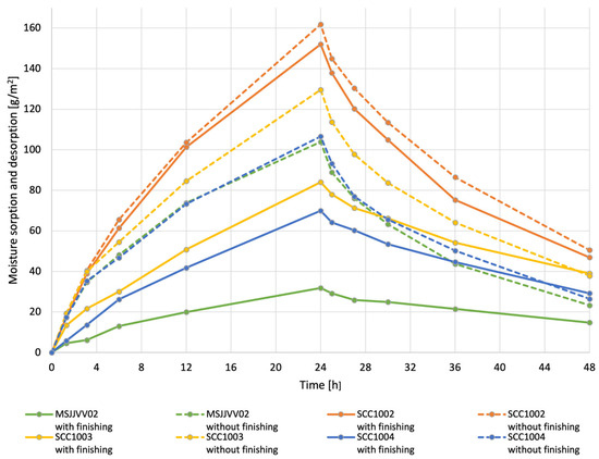
Figure 12.
Adsorption/desorption curves of the 24 h plus 24 h tests of the four case studies, with (full line) and without (dotted line) the finishing layer.
The MSJJVV_02 case study presents a major difference in the sorption value between the specimens with and without the finishing layer, where the samples with no finishing have 3.3 times more sorption than the samples of the same case study with their finishing. The finishing layers are identified as mainly lime and gypsum paints and gypsum-based thin paste with vinylic binder and glued wallpaper in the visible surface. In the SCC10_03A (lime- or gypsum-based mortars and vinylic or acrylic paint finishings) and SCC10_04 (calcium carbonate mortar and vinylic or acrylic paint finishing) case studies, the specimens without the finishing layer present an increase of 1.5 in the sorption value after 24 h in comparison to the specimens with the finishing layer.
The whole specimens with all layers, including the finishings, after 24 h adsorbing water vapor, present the following results: the MSJJVV_02 complete sample presents the lowest adsorption, with 31.9 g/m2; the SCC10_04 and the SCC10_03A case studies adsorbed 84.0 and 70.0 g/m2, and the highest value of sorption, with 152.0 g/m2, is presented by the case study SCC10_02. This last case study has the simplest finishing layer: a limewash or gypsum-based paint that once covered the earthen base coat, and is now in an advanced state of degradation, leaving this coat very much exposed and in the ‘front line’ of the sorption surface.
Concerning the samples with no finishings, composed of the two earth layers, the difference in the sorption values between them tends to be shorter, even though significant, as shown in Figure 12.
Comparing to other results with the same test and procedure, but using single-layer laboratory specimens with dimensions according to DIN 18947 [20], after 24 h of sorption exposure at 80% RH and 23 ± 5 °C, Lima and Faria [27], with a different fiber mix on earthen mortars, reached circa 84 g/m2, while Santos et al. [28] and Ranesi et al. [12] (the latter using much smaller samples) with a commercial premixed earthen mortar, reached a sorption of 104 g/m2 and 99.3 g/m2, respectively. The results of this study, with specimens without finishing, present results between 103 and 161 g/m2, showing the high capacity of the tested vernacular plasters to contribute to equilibrate indoor RH. Other results from several researchers are compared in McGregor et al. [29], where the adsorption values at 8 h of exposure to 75% and 80% RH vary between 30 and 70 g/m2. The results of the samples without finishing layers presented in this article, after 8 h of exposure to 80% RH, vary approximately from 55 to 80 g/m2. The results of the same case studies with finishing layers are significantly lower.
In the aforementioned work, McGregor et al. [29], compares commercial plasters with and without a 3 mm finishing coat, both composed of earth. The difference between the moisture sorption results of the plasters with or without the finishing coat are barely visible, demonstrating the minor influence of these topcoats, being of the same material of its undercoat, contrary to the results of the case studies here presented with finishing layers composed of different materials. In Santos et al. [30], commercial premixed earthen mortar, with and without a limewash layer, is compared, showing small differences in hygroscopic behavior, as occurs in the SCC10_02 case study.
Compared with other material-based plasters, in Santos et al. [28], the results at 24 h of sorption are 40 g/m2 for a cement mortar and 22 g/m2 for a hemihydrate gypsum-based mortar.
All studied case studies without their finishing layer are classified in the WSIII class (≥60 g/m2), the most hygroscopic as proposed by the DIN 18947 [20], on sorption up to 12 h. In the case of the SCC10_02 case study, the same is valid for the specimens’ set with the finishing layer, as they present a similar behavior.
In the case studies without finishing, the rough texture left by the removed surface layer could have influenced the sorption results [12], although, in the SCC10_02 case study, there is no significant difference between both sets, with or without finishing. However, this might be associated with the water-rained paint finishing that, in this case study, presents a slightly rougher texture surface as well. It is noted that the moisture buffering of coatings is important to indoor coatings (plasters) and not for outdoor coating, such as this render.
The hysteresis phenomena of the case studies are more significant in the samples with the finishing layers, where desorption reaches only 53% to 58% of the sorption value, in the case of MSJJVV_02, SCC10_03A, and SCC10_04. For the same case studies, concerning the coatings without finishing layers, the values of the desorption are higher, representing between 70% and 77% of the sorption values, meaning the difference between sorption and desorption, in these cases, is lower. In fact, although the sorption values of the case studies without finishing is from 1.5 to 3.3 higher, their desorption value after 24 h, as shown in Figure 12, is not so different.
As for the SCC10_02 sample’s coating, the values of sorption are similar, and the desorption performance reached, both with and without finishing, 69% of the sorption value, as shown in Table 2.
Table 2.
Comparative analysis of the sorption and desorption test, with and without the finishing layer: maximal values of moisture content (MC) at 24 h (sorption) and at 48 h (desorption), percentage of released MC, and ratio of sorption in each case study.
4. Conclusions
The sorption behavior of the vernacular coatings of the four tested case studies revealed significant differences, mainly derived from the hygroscopic nature of the materials used as finishing systems. The differences reported from the specimens after removal of the finishing layer for each case study are minor, if compared to the results obtained with the samples including the whole coating, finishing system included. While the earthen coatings without finishings have a very high sorption capacity, this behavior is limited according to the set of gypsum- or lime-based pastes, paints, or wallpaper finishing that coats them. The least interfering finishing on the hygroscopic behavior of the two-layer earthen system is limewash. Comparing the specimens with and without finishing of this case study (SCC10_02), they present minimal differences in water vapor adsorption. The SCC10_03A and SCC10_04 case studies, both with lime or gypsum mortars and organic-based paint (vinyl or acrylic), present similar behavior in the relation between the specimens with and without finishing. The case study MSSJJVV_02, having a more complex set of finishing layers, from traditional lime pastes and paints to commercial lime-vinyl binder pastes and glued wallpaper, presents the specimens with the lowest water vapor adsorption.
The set of finishing layers is the result of successive applications at different times during the lifetime of the coated surface, for aesthetics and conservation of repair works on the walls. This multiple overlap of finishing material layers is identified in almost every case study of this and previous campaigns in this same territory. To better understand the effective influence of each of these specific materials on the hygroscopic properties of the coating systems, other tests are being carried out with specimens with known single finishing trying to better understand the processes and obtain more accurate results and conclusions. Along with these, the moisture buffering value and water vapor permeability tests are also being considered for the coating samples, providing complementary data about their hygroscopic capacity and hysteresis phenomenon. In addition to the finishings, it is also important to distinguish the hygroscopic properties of both layers of earth in this system, separately. Their different composition and cohesion, one crumbly and with a sandy texture, the other more cohesive and with plant fibers, can have different influences on the results, as can the different finishings.
Although it is essential to continue the research for more accurate conclusions, the previous results show the great buffering capacity of this two-layer earthen system, which is least limited with thinner and few finishing layers.
Author Contributions
Conceptualization, writing—original draft preparation, visualization, P.M., A.R.V. and S.M.; investigation, methodology, P.M., A.R.V., S.M., A.N.E. and P.F.; formal analysis, data curation, P.M. and S.M.; resources and project administration, P.M.; writing—review and editing, supervision, P.F., A.N.E. and M.A. All authors have read and agreed to the published version of the manuscript.
Funding
The laboratory tests were financed by the Laboratori de Materials of the Barcelona School of Building Construction EPSEB, Universitat Politècnica de Catalunya—BarcelonaTech; “Proyecto J-02977 TED2021-129705B-C32” TERRA-CYCLE funded by MCIN/AEI/10.13039/501100011033 and European Union NextGeneration EU/PRTR, and CERIS Laboratories at NOVA University Lisbon. The authors acknowledge the financial support of the Foundation for Science and Technology (FCT) through the project UIDB/04625/2025 of the research unit CERIS and the Chilean National Fund for Cultural Development and the Arts, National Funding Fund, Call 2024, n.º 734164.
Data Availability Statement
The original contributions presented in this study are included in the article. Further inquiries can be directed to the corresponding author.
Acknowledgments
Ph.D. Scholarship statement, P.M. and A.RV.: article was produced while attending the PhD program in Civil Engineering and Architecture at the University of Cagliari, Cycle XXXVIII and XXXVII, respectively. PhD Scholarship statement, S.M.: This article was produced while attending the Ph.D. program in Chemical Sciences and Technology at the University of Cagliari, Cycle XXXVIII, with the support of a scholarship financed by the Ministerial Decree no. 351 of 9 April 2022, based on the NRRP funded by the European Union-NextGenerationEU-Mission 4 “Education and Research”, Investment 4.1. Extension of the number of research doctorates and innovative doctorates for public administration and cultural heritage.
Conflicts of Interest
There are no conflicts to declare.
Appendix A
Table A1.
Average thickness of the two layers of the earthen coatings of eleven samples extracted from historical buildings of the center of Santiago, and identification of the supporting wall structure and of the internal or external location of the coatings [11].
Table A1.
Average thickness of the two layers of the earthen coatings of eleven samples extracted from historical buildings of the center of Santiago, and identification of the supporting wall structure and of the internal or external location of the coatings [11].
| Samples | ES (mm) | EF (mm) | Substrate | Coating local |
|---|---|---|---|---|
| MN_C10_1 | 40.0 | 10.0 | Adobe | Interior |
| SC_C10_02 | 12.5 | 12.5 | Adobe | Exterior |
| SC_C10_03 | 17.5 | 10.0 | Adobe | Interior |
| MS_TOC_01 | 20.0 | 6.0 | Fired brick | Interior |
| MS_TOC_02 | 25.0 | 20.0 | Adobe-filled timber frame—adobe en pandereta | Interior |
| MS_TOC_03 | 30.0 | 20.0 | Fired brick | Interior |
| BY_CHA_01 | 20.0 | 10.0 | Embedded adobe-filled timber frame—adobillo | Interior |
| BY_JJVV_01 | 45.0 | 10.0 | Adobe | Interior |
| BY_MAK_01 | 22.5 | 5.0 | Earth- and fiber-filled timber frame—quincha | Interior |
| BY_MAK_02 | 17.5 | 10.0 | Adobe | Exterior |
| MS_JJVV_01 | 20.0 | 10.0 | Adobe-filled timber frame —adobe en pandereta | Exterior |
| Thickness Average | 24.5 | 11.2 |
Notation: Average thicknesses of ES—earth and sand layer, EF—earth and fiber layer.
References
- Jorquera, S.N.; Soto, R.C. The Basement of the San Francisco Church: An Earthquake-Resistant Foundation on a Prehispanic Layer? ARQ Santiago 2016, 93, 106–117. [Google Scholar] [CrossRef]
- Benavides Rodríguez, A.; Benavides Courtois, J. La Arquitectura en el Virreinato del Perú y en la Capitanía General de Chile; Editorial Andrés Bello: Santiago, Chile, 1988. [Google Scholar]
- Jorquera, N. Patrimonio Chileno Construido en Tierra; ARQ Ediciones: Santiago, Chile, 2022. [Google Scholar]
- Rivera Vidal, A.; Gómez Maestro, C. Heritage and Community Centre in Matta Sur, Chile. In Proceedings of the HERITAGE2022 International Conference on Vernacular Heritage: Culture, People and Sustainability, Valencia, Spain, 15–17 September 2022; UPV: Valencia, Spain, 2022; pp. 1063–1069. [Google Scholar] [CrossRef]
- Bass, A.; Porter, D.; Spilde, M.; Guebard, M.; Shaum, K.; Ferriola, N. Characterization and Comparative Analysis of Ancient Earthen Plasters from the American Southwest. MRS Adv. 2017, 2, 2145–2178. [Google Scholar] [CrossRef]
- Veiga, M.R.; Santos Silva, A.; Tavares, M.; Santos, A.R.; Lampreia, N. Characterization of Renders and Plasters from a 16th Century Portuguese Military Structure: Chronology and Durability. Restor. Build. Monum. 2013, 19, 223–238. [Google Scholar] [CrossRef]
- Salavessa, E.; Jalali, S.; Sousa, L.M.O.; Fernandes, L.; Duarte, A.M. Historical Plasterwork Techniques Inspire New Formulations. Constr. Build. Mater. 2013, 48, 858–867. [Google Scholar] [CrossRef]
- Beas, M.I.G. Traditional Architectural Renders on Earthen Surfaces. Master’s Thesis, University of Pennsylvania, Philadelphia, PA, USA, 1991. Available online: https://repository.upenn.edu/hp_theses/395 (accessed on 24 May 2025).
- Marchante, P.; Silva, P. Los revestimientos en la conservación del patrimonio construido con tierra en Santiago de Chile. Mem. Semin. Iberoam. Arquit. Constr. Con Tierra-SIACOT 2017, 17, 400–406. [Google Scholar]
- Marchante, P.; Vidal, A.R. Characterization of Traditional Coatings in Earthen Vernacular Architecture in the Limarí Valley: Their Role in the Conservation of Built Heritage in Chile. J. Tradit. Build. Archit. Urban. 2022, 3, 384–395. [Google Scholar] [CrossRef]
- Marchante, P.; Rivera Vidal, A.C. Revestimientos Tradicionales de Santiago, 1st ed.; MINCAP: Santiago, Chile, 2023. [Google Scholar]
- Ranesi, A.; Faria, P.; Veiga, M.R. Traditional and Modern Plasters for Built Heritage: Suitability and Contribution for Passive Relative Humidity Regulation. Heritage 2021, 4, 2337–2355. [Google Scholar] [CrossRef]
- Jorquera-Silva, N.; Lobos-Martínez, M.L. Technique and Material Configuration of Santiago de Chile’s Old Town at the Beginning of the 20th Century. An Interpretation Based on Municipal Cadasters from 1910 to 1939. AUS 2017, 22, 46–52. [Google Scholar] [CrossRef]
- Rivera Vidal, A.; Gómez Maestro, C.; Marchante, P. Matta Sur, ejemplo de patrimonio urbano de tierra en Santiago, Chile. Mem. Semin. Iberoam. Arquit. Constr. Con Tierra-SIACOT 2023, 21, 532–540. [Google Scholar]
- Candeias, A.E.; Nogueira, P.; Mirão, J.; Santos Silva, A.; Veiga, R.; Gil Casal, M.; Ribeiro, I.; Seruya, A.I. Characterization of Ancient Mortars: Present Methodology and Future Perspectives. In Ext. Abst. of CERC3 Workshop on Chemistry in the Conservation of Cultural Heritage, EU-ARTECHP; John Wiley and Sons: Hoboken, NJ, USA, 2006; pp. 4–7. [Google Scholar]
- Volhard, F. Light Earth Building: A Handbook for Building with Wood and Earth; Birkhäuser: Basel, Switzerland, 2016. [Google Scholar]
- Feigl, F. Spot Tests in Organic Analysis; Elsevier Science B. V.: Amsterdam, The Netherlands, 1966. [Google Scholar] [CrossRef]
- Feigl, F.; Angern, V. Spot Tests in Inorganic Analysis; Elsevier Science B. V.: Amsterdam, The Netherlands, 1972. [Google Scholar]
- Kulkarni, V.S.; Shaw, C. Use of Polymers and Thickeners in Semisolid and Liquid Formulations, In Essential Chemistry for Formulators of Semisolid and Liquid Dosages; Academic Press: Cambridge, MA, USA, 2016; pp. 43–69. [Google Scholar] [CrossRef]
- DIN 18947; Earth Plasters—Requirements, Test and Labelling. Deutsches Institut fur Normung: Berlin, Germany, 2024.
- Lima, J.; Faria, P.; Santos Silva, A. Earth plasters: The influence of clay mineralogy in the plasters’ properties. Int. J. Archit. Herit. 2020, 14, 948–963. [Google Scholar] [CrossRef]
- Odegaard, N. Microchemical Tests in Conservation. In The Encyclopedia of Archaeological Sciences; López Varela, S.L., Ed.; John Wiley & Sons: Hoboken, NJ, USA, 2018. [Google Scholar] [CrossRef]
- Doménech-Carbó, M.T.; Doménech-Carbó, A. Spot tests: Past and present. ChemTexts 2022, 8, 4. [Google Scholar] [CrossRef] [PubMed]
- Pasta muro Interior. Available online: https://www.sipa.cl/productos/pasta-muro-y-selladores/pasta-muro-interior (accessed on 21 March 2025).
- Siedel, H.; Siegesmund, S.; Sterflinger, K. Characterisation of Stone Deterioration on Buildings. In Stone in Architecture; Springer: Berlin/Heidelberg, Germany, 2011; pp. 347–410. [Google Scholar] [CrossRef]
- Braun, J.H.; Baidins, A.; Marganski, R.E. TiO2 Pigment Technology: A Review. Prog. Org. Coat. 1992, 20, 105–138. [Google Scholar] [CrossRef]
- Lima, J.; Faria, P. Eco-efficient earthen plasters: The influence of the addition of natural fibers. In Natural Fibres: Advances in Science and Technology Towards Industrial Applications. From Science to Markets; Fangueiro, R., Rana, S., Eds.; RILEM Bookseries; Springer: Dordrecht, The Netherlands, 2016; Volume 12, pp. 315–327. [Google Scholar] [CrossRef]
- Santos, T.; Gomes, M.I.; Silva, A.S.; Ferraz, E.; Faria, P. Comparison of Mineralogical, Mechanical and Hygroscopic Characteristic of Earthen, Gypsum and Cement-Based Plasters. Constr. Build. Mater. 2020, 254, 119222. [Google Scholar] [CrossRef]
- McGregor, F.; Heath, A.; Maskell, D.; Fabbri, A.; Morel, J.-C. A Review on the Buffering Capacity of Earth Building Materials. Proc. Inst. Civ. Eng.-Constr. Mater. 2016, 169, 241–251. [Google Scholar] [CrossRef]
- Santos, T.; Faria, P.; Sotomayor, J.; Silvestre, J.D.; Santos Silva, A. Effect of Different Surface Treatments on the Performance of Earth Plasters. Coatings 2024, 14, 1537. [Google Scholar] [CrossRef]
Disclaimer/Publisher’s Note: The statements, opinions and data contained in all publications are solely those of the individual author(s) and contributor(s) and not of MDPI and/or the editor(s). MDPI and/or the editor(s) disclaim responsibility for any injury to people or property resulting from any ideas, methods, instructions or products referred to in the content. |
© 2025 by the authors. Licensee MDPI, Basel, Switzerland. This article is an open access article distributed under the terms and conditions of the Creative Commons Attribution (CC BY) license (https://creativecommons.org/licenses/by/4.0/).