1. Introduction
In the context of global urbanization, the development and utilization of urban underground space are increasingly oriented toward intensification and deep-level construction [
1,
2]. Utility tunnels, as critical infrastructures for the centralized installation of municipal pipelines, demonstrate 40–60% higher spatial efficiency compared to traditional direct-buried pipelines [
3,
4], positioning them as strategic priorities in smart city underground infrastructure development. Compared to open-cut methods, pipe jacking technology enables non-disruptive tunneling through sensitive areas with deformation control precision of 3–5 mm [
5,
6], exhibiting significant technical advantages in utility tunnel engineering [
7]. However, when jacking distances exceed 100 m, cumulative frictional resistance induces nonlinear surges in thrust forces [
8], while existing predictive models exhibit errors as high as 50% in complex strata [
9], posing critical challenges to the safety and cost-effectiveness of ultralong pipe jacking projects.
Frictional resistance during pipe jacking involves intricate multi-physics coupling mechanisms. While face resistance is predominantly governed by cutterhead excavation parameters [
10,
11], the contribution of lateral frictional resistance can exceed 85% in long-distance drives [
12]. Classical theoretical frameworks require comprehensive integration of critical factors such as soil pressure redistribution [
13], grouting time-dependency [
14,
15,
16], and interface contact evolution [
17,
18]. Nevertheless, the Terzaghi soil arching model demonstrates discrepancies in shallow sandy strata due to oversimplification of soil rheological behavior [
19], while cohesive effects in rock layers invalidate interface negative pressure calculations [
20]. Recent advancements, including improved contact coefficient methods [
21], time-dependent slurry constitutive models, and thermo-mechanical coupling analyses [
22], have reduced prediction errors to below 10% under specific conditions [
23,
24]. Prior studies reveal the dynamic evolution of pipe–soil–slurry interfaces during jacking, where tunnel deflection and alignment deviations form a positive feedback mechanism. However, prevailing models relying on rigid contact assumptions fail to accurately characterize the dynamic evolution of interfacial interactions during construction.
To address these limitations, this study first conducts an in-depth analysis of alignment deviation monitoring data to establish predictive equations for excavation profiles. Subsequently, based on the Winkler elastic foundation theory, deflection curves of jacked pipelines are derived for varying thrust distances. Integrating excavation profiles with pipeline deflection curves, a quantitative computational framework is proposed to resolve complex pipe–soil–slurry contact configurations. A dynamic evaluation criterion for interface contact states is established, culminating in a novel frictional resistance prediction methodology for long-distance rectangular pipe jacking that accounts for intricate contact dynamics. Validation through real-world engineering case studies confirms the method’s reliability, providing a robust theoretical foundation for the design and construction of ultralong pipe jacking projects.
2. Construction Effects and Contact States in Rectangular Pipe Jacking
During pipe jacking construction, axis deviation of the pipe jacking machine is inevitable. Particularly in soft soil strata, the heavy cutterhead often induces a “snaking phenomenon”, causing gradual deviation from the intended jacking direction. The longer the jacking distance, the more pronounced this offset becomes. In soft soils, the substantial weight of assembled pipe segments leads to deflection deformation under self-weight before integral tensioning. As jacking progresses, this deflection intensifies, resulting in a long-distance pipe deformation effect.
2.1. Deviation Effect of Pipe Jacking Machine
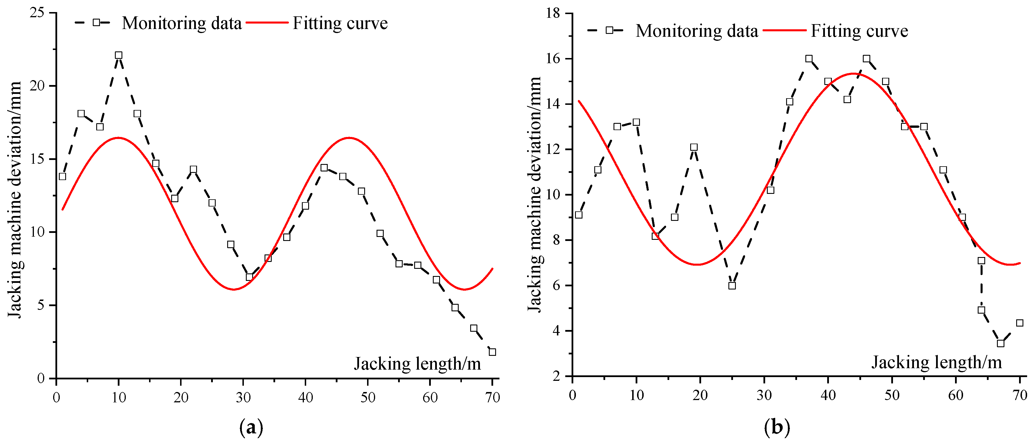
The axis deviation of the pipe jacking gradually increases with advancement distance. When the deviation exceeds a specific threshold, steering correction measures are typically implemented to mitigate the axis offset and prevent loss of attitude control, ensuring the machine reaches the predetermined position of the receiving shaft. The interaction between axis deviation and steering correction constitutes a dynamic adjustment process, which explains why the monitored deviation data exhibit distinct variation patterns.
The No. 1 and No. 2 pipe jacking tunnels located on Hongzuan Road have a total length of 105 m, with an approximate burial depth of 10 m. These tunnels primarily traverse a silt soil layer. The cross-sectional dimensions of Tunnel No. 1 are 10.1 m in width by 7.25 m in height, while those of Tunnel No. 2 are 7.50 m in width by 5.40 m in height. The construction process utilized two earth-pressure balance pipe jacking machines. The vertical axis deviation monitoring results are illustrated in
Figure 1.
The axis deviation of the pipe jacking machine exhibits significant periodic characteristics, along with a persistent upward deviation trend during long-distance jacking. Due to its heavier weight compared to the pipe segments, the machine’s cutterhead compresses the underlying soil during jacking, thereby inducing a downward deviation tendency. When the machine’s deviation reaches a critical distance, upper steering correction is performed to reduce the downward offset. This dynamic interaction results in a periodic deviation pattern of the machine’s axis, as shown in
Figure 1a,b. The displacement of the machine’s central axis is expressed by Equation (1), as follows:
where
A represents the amplitude of jacking machine deviation, determined by the threshold of the pipe jacking equipment during advancement, and is generally constrained within 50 mm.
z0 denotes the initial incision deviation generated during the jacking stage, which depends on the machine model and the physical properties of the stratum near the launching shaft, typically around 10 mm.
m is the frequency of steering corrections, influenced by construction conditions and technical specifications
(when corrections are applied per t meters of jacking distance).
φ0 refers to the initial phase angle of the machine deviation during the jacking process.
2.2. Longitudinal Deformation Effect of Pipe Jacking
In soft soil strata, as the pipe jacking machine advances and pipe segments are spliced, the assembled pipe segments undergo downward deflection deformation due to their substantial weight. To calculate this deflection, the spliced pipe is modeled as a Winkler elastic foundation beam subjected to overlying soil pressure
q and self-weight
G. During construction, the pipe is constrained by two boundary conditions: the launching shaft constraint at the tail of the pipe segments and the pipe jacking machine constraint at the front end. Both constraints can restrict horizontal and vertical displacements, thereby functioning as hinged supports, as illustrated in
Figure 2.
According to the elastic foundation beam theory, the differential equation of the deflection curve for the pipe jacking mechanical model is derived as follows:
where
denotes the deflection curve equation of the pipe;
represents the bending stiffness of the pipe;
corresponds to the external load applied to the pipe, which is defined as the sum of the overlying soil pressure and the self-weight of the pipe; and
indicates the subgrade reaction from the foundation.
According to the assumption of the elastic foundation beam,
, where
k is the subgrade reaction coefficient of the soil layer at the lower surface of the pipe jacking. As described in the literature [
19], the value of the subgrade reaction coefficient
k is related to the burial depth, pipe section stiffness, and soil properties, and can be determined according to the following formula:
where
is the depth influence factor, whose value is calculated by the following formula:
where
h is the burial depth of the pipe section, and
B is the width of the pipe section.
With the origin
O set at the launching shaft, and considering the deviation of the pipe jacking machine by a distance
n,
Hence, the equation describing the centerline of the pipe segment, accounting for the deflection caused by the pipe jacking machine, is given by the following equation:
where
;
;
;
;
;
is the section where the distance between the left end of the
y section and the endpoint
O is measured when the deflection
is solved for any
x section,
.
Subsequently, the deflection equation
yS(
x,
y) for the upper side of the pipe, is given by the following equation:
The deflection equation
yX(
x,
y) for the lower side of the pipe, is given by the following equation:
Combining the analysis of the central axis of the pipe jacking machine in Equation (1), the upper excavation profile
is as follows:
The lower excavation profile
is as follows:
2.3. Determining Method for Contact States Considering Pipe Jacking Construction Effects
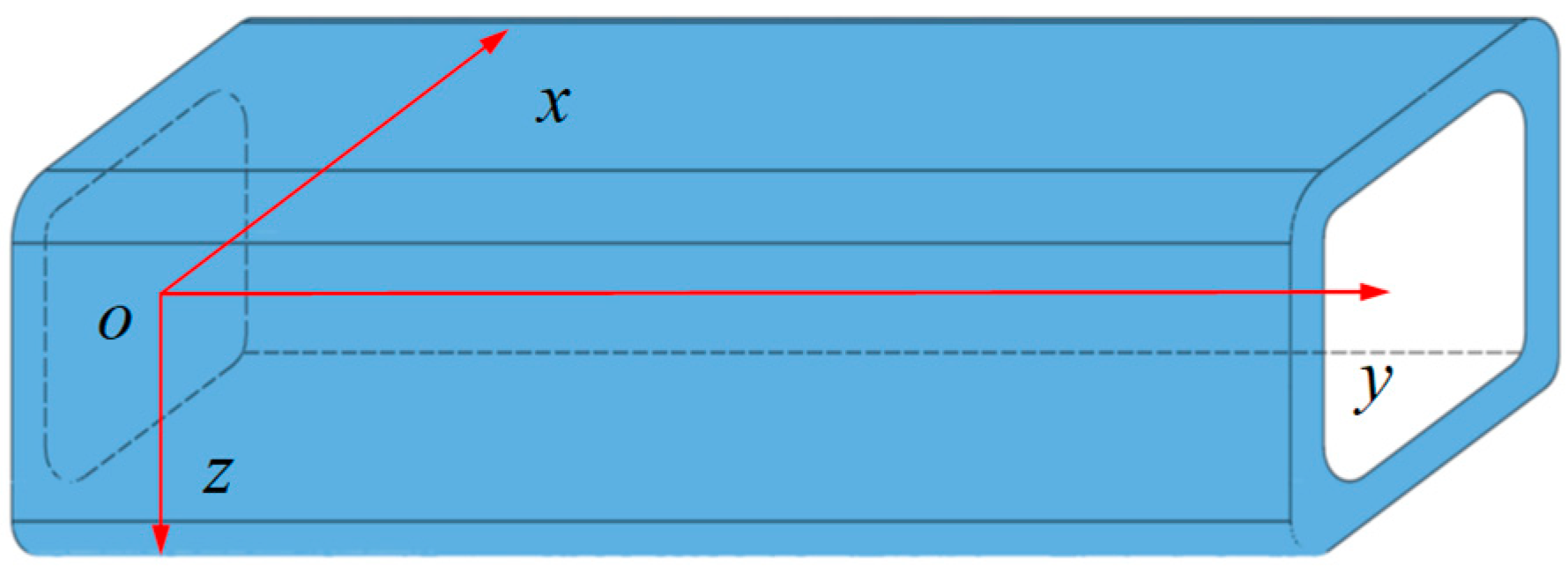
With the increase in jacking distance, the influence of angular deviation caused by the attitude of the pipe jacking machine on the jacking force gradually diminishes, while the deflection of pipe segments becomes increasingly pronounced. Concurrently, the control difficulty of machine deviation surges exponentially with advancing distance, leading to alterations in the excavation face geometry of the jacking machine. These changes significantly amplify the complexity of pipe–soil/slurry interactions, necessitating the establishment of the coordinate system illustrated in
Figure 3.
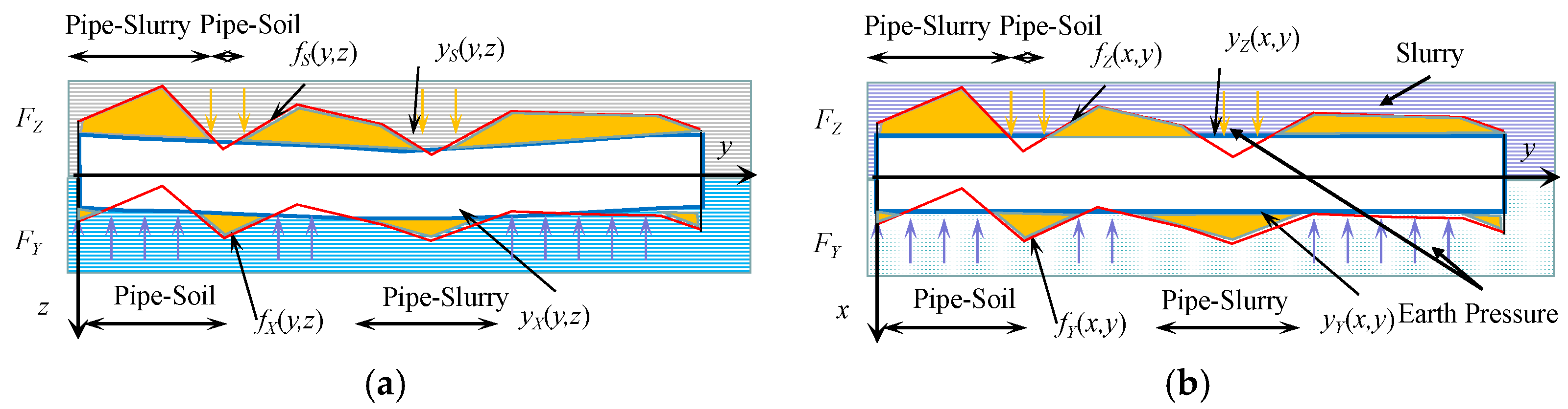
Based on the established coordinate system, the complex contact forms of the pipe jacking are analyzed, as shown in
Figure 4. The upper, lower, left, and right excavation profiles after the pipe jacking machine excavates are
,
,
, and
respectively. In the
yoz plane, the pipe segment will have a certain deflection under the action of the upper soil pressure
Fs and its own gravity
G. In the
xoy plane, the pipe segment is affected by the soil pressure on both sides, but lateral deformation of the pipe segment can be ignored. The upper, lower, left, and right curves of the pipe segment are
,
,
, and
, respectively.
In the process of pipe jacking, it is necessary to consider not only the change of the excavation surface caused by the deviation of the jacking machine but also the deflection changes of the jacking. Under the joint action of the two, the constant change of pipe–soil/slurry contact form in the long-distance jacking process is formed. The excavation contour line left by the pipe jacking machine deviation is , and the curve around the pipe jacking segment is . When the geometric profile of the pipe segment lies entirely within the excavation contour, an annular gap exists between the outer pipe wall and the excavation boundary, which is filled with pressurized slurry. In this scenario, the interaction between the pipe and the surrounding medium is classified as a pipe–slurry contact state. Conversely, if the pipe profile extends beyond the excavation contour, no such gap exists, resulting in direct contact between the pipe exterior and undisturbed soil. This condition is defined as a pipe–soil contact state. Therefore, the following criteria for determining pipe–soil/slurry contact are formed:
- (1)
In the yoz plane, the upper and lower sides of the pipe jacking joint are affected by the upper side soil pressure q and its own gravity G.
- ➀
When > , the upper side of the pipe is in pipe–slurry contact;
when ≤ , the upper side of the pipe is in pipe–soil contact;
- ➁
When > , the lower side of the pipe is in pipe–soil contact, when ≤ , the lower side of the pipe is in pipe–slurry contact.
- (2)
In the xoy plane, transverse deformation of the pipe joint is ignored , and the left and right sides of the pipe joint are straight lines.
- ➀
When > , the left side of pipe jacking is in pipe–slurry contact; when ≤ , the left side of pipe jacking is in pipe–soil contact;
- ➁
When > , the right side of the pipe is in pipe–soil contact, when ≤ , the right side of the pipe is in pipe–slurry contact.
3. Frictional Resistance Calculation Method Accounting for Complex Contact States
Based on the method for determining complex contact states, a quantitative approach for distinguishing pipe–soil and pipe–slurry interactions is established. When pipe–soil contact occurs, the soil directly interacts with the pipe segment. In this case, the frictional resistance is calculated using Newton’s friction law. When pipe–slurry contact occurs, the slurry is gelled in the stationary state, and the positive stress between the pipe joint and the slurry is difficult to determine and the application of Newton’s law of friction is limited. To address this, the moving mud is modeled as a viscous fluid, and the frictional resistance is derived from fluid mechanics principles.
3.1. Friction Resistance Calculation of Pipe–Soil Contact State
When pipe–soil contact occurs, the friction resistance is calculated using the following equation:
where
μ is the friction coefficient between the rectangular jacking pipe and soil, and
is the positive stress of the pipe–soil contact section.
Therefore, the core of frictional resistance calculation for pipe–soil contact lies in determining the pipe–soil friction coefficient and the interfacial normal stress. Through systematic analysis of concrete pipe jacking projects, friction coefficients between concrete pipes and soils with varying geotechnical properties have been statistically derived, as presented in
Table 1.
Currently, conventional methodologies for calculating pipe–soil interfacial normal stress predominantly employ Boussinesq theory, Rankine’s earth pressure theory, and limit equilibrium conditions. However, these approaches neglect the soil pressure increment induced by pipe-induced radial compression of surrounding soils during jacking operations. To address this limitation, a computational framework is established through analytical integration of the excavation face geometry and the longitudinal deflection profile of the jacked pipeline, explicitly incorporating pipe-induced soil compression effects.
For the upper side of a rectangular pipe jacking structure, the earth pressure induced by pipe deformation under self-weight and grouting pressure is negligible. However, for the lower side of the rectangular pipe, as the jacking distance increases, the cumulative deflection of the pipe under its own weight progressively compresses the underlying soil. Therefore, by combining the excavation face equation at the lower side of the pipe with the deflection curve equation of the jacked pipeline, the earth pressure at the lower side of the pipe can be derived as follows:
For the sides of the rectangular pipe jacking structure, unlike the upper and lower sections, there is no significant deflection deformation similar to that of the pipe jacking machine. Consequently, the degree of soil compression on both sides is far less than that on the lower side. Therefore, in calculating the lateral earth pressure on the pipe sections, the contribution of soil compression is neglected to simplify the computation. The soil pressure on the left side is therefore as follows:
The soil pressure on the right side is as follows:
where
is the lateral pressure coefficient.
3.2. Calculation Method of Friction Resistance of Pipe-Slurry Contact State
The existence of grout-reduced mud slurry exhibits fluidity and viscosity. Therefore, the pipe–mud contact resistance during the jacking process is calculated based on the viscous fluid mechanics Navier–Stokes (N–S) equations. The following assumptions are made:
- (1)
Changes in the groundwater level of the stratum and the influence of the surrounding environment are not considered.
- (2)
During the jacking process, the mud slurry fully fills the gap between the pipes and the soil, without infiltrating the soil matrix.
- (3)
The grouting pressure equals the surrounding soil pressure, and the mud slurry is treated as an incompressible fluid.
- (4)
The soil remains stationary, and the movement of soil in contact with the mud slurry caused by jacking is ignored.
- (5)
The entire jacking process is performed at a uniform speed.
Under these assumptions, a differential element of the slurry body at any point G(
x,
y,
z), with volume
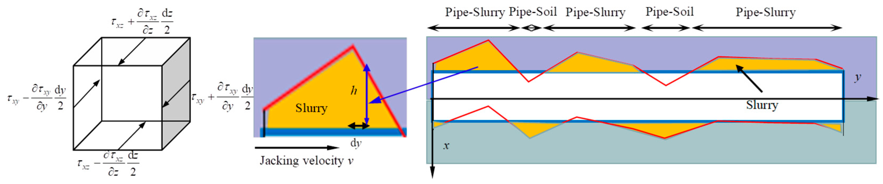
dxdydz, is subjected to body forces and surface forces during jacking. Due to the viscous nature of the mud slurry, both shear stresses and normal-direction shear stresses exist. The stress components vary across different directional planes of the element. To simplify the analysis, a simplified analytical model is adopted, as illustrated in
Figure 5.
Based on hypothesis (2), the mechanical equation of the slurry unit in the jacking process can be simplified as follows:
As shown in
Figure 5, the jacking speed of the pipe jacking machine along the jacking direction is denoted as U. At position
dy, the filling height of the slurry between the pipe and the surrounding soil is ℎ. Since the jacking speed remains constant along the pipe segment length direction and the process operates under uniform-speed conditions, then
Under conditions where the slurry is unaffected by earth pressure, the flow velocity of the slurry within the same z-plane remains uniform. Therefore,
, there is:
The above equation is a second-order linear differential equation with constant coefficients. To solve the equation, boundary conditions must be established. By incorporating assumptions (3) and (4), the boundary conditions can be derived as follows:
By combining Equations (15)–(20), the distribution function of the slurry at any cross-section in the y-direction is obtained as follows:
The shear stress of the upper slurry layer on the rectangular pipe jacking and the shear stress exerted by the slurry on the pipe jacking form a pair of interaction forces. Therefore, the upper side frictional resistance of the rectangular pipe is as follows:
Similarly, the calculation formula for the lower side frictional resistance is as follows:
The left-side frictional resistance calculation formula is as follows:
The calculation formula for the right-side frictional resistance is as follows:
3.3. The Calculation Method of Friction Resistance
Based on the relationship between the excavation face curve and the pipe segment curve, the pipe–soil/mud contact patterns were quantitatively determined. Newton’s friction law and the Navier–Stokes (N–S) equations were employed to calculate the frictional resistance for pipe–soil and pipe–mud contact modes, respectively. Ultimately, a calculation method for frictional resistance in long-distance rectangular pipe jacking, considering complex contact patterns, was proposed.
The friction resistance at any point on the upper side can be expressed as follows:
The friction resistance at any point on the lower side can be expressed as follows:
The friction resistance at any point on the left side can be expressed as follows:
The friction resistance at any point on the right side can be expressed as follows:
The jacking force of the rectangular pipe jacking is mainly composed of friction resistance
Fm and head-on resistance
Fz. Therefore, the jacking force prediction formula is proposed as follows:
where
is the friction coefficient for pipe–soil contact on different sides, considering the grouting effect;
is the coefficient of slurry viscosity;
u is the jacking speed; and
is the head-on resistance.
4. Case Verification and Parameter Analysis
4.1. Case Verification
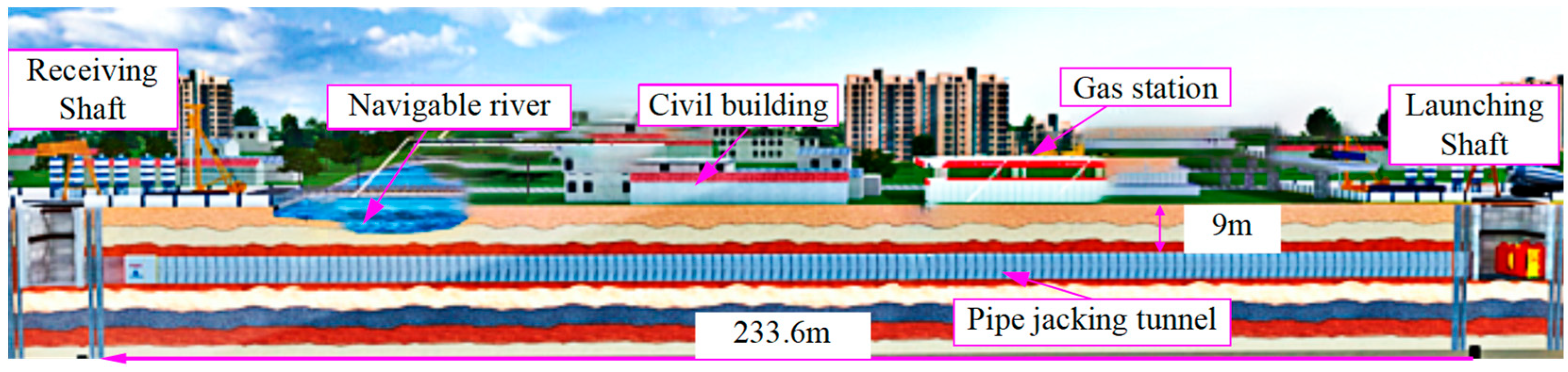
The Suzhou Chengbei Road Utility Tunnel Project involves the construction of a main utility tunnel with a length of approximately 1365.08 m. The ground surface along the alignment contains critical structures such as rivers, gas stations, residential buildings, and the Qimen Overpass, as shown in
Figure 6. Due to spatial constraints, the pipe jacking requires a single continuous thrust over a long distance of 233.6 m. The average overburden thickness in the jacking section is 9.1 m, with a cross-sectional dimension of 9.1 m (width) × 5.5 m (height).
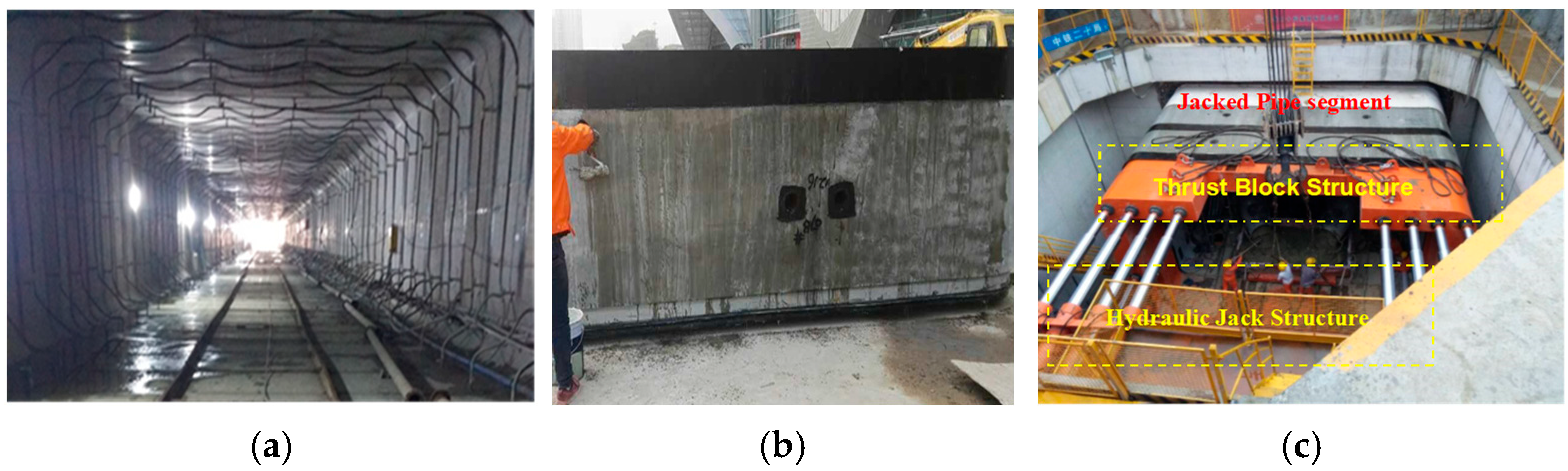
Given the extended jacking distance and large cross-sectional size, multiple friction reduction measures have been implemented to ensure safety, including grouting lubrication and wax coating on pipe segments, as shown in
Figure 7. The jacking passes through highly porous silty sand and silt layers in water-rich areas, where conventional low-fluid-loss grout tends to dissipate rapidly. Therefore, a thixotropic slurry with high fluid loss and low viscosity has been adopted to meet the requirements of filtration control in silty strata, viscosity adaptation in water-rich zones, and long-distance friction reduction. Key parameters of the slurry and soil are detailed in
Table 2 and
Table 3.
The lateral deviation amplitude during jacking exerts a more significant influence on frictional resistance than the deviation period. Consequently, a stringent deviation threshold (±50 mm) has been set. A laser theodolite is employed to monitor real-time deviations by projecting a laser beam onto the jacking machine. When deviations reach the ±50 mm threshold, corrective measures are immediately initiated by adjusting the thrust of hydraulic jacks to control the advancement speed until the target distance is achieved. The total thrust force is continuously monitored through pressure sensors on the jacks.
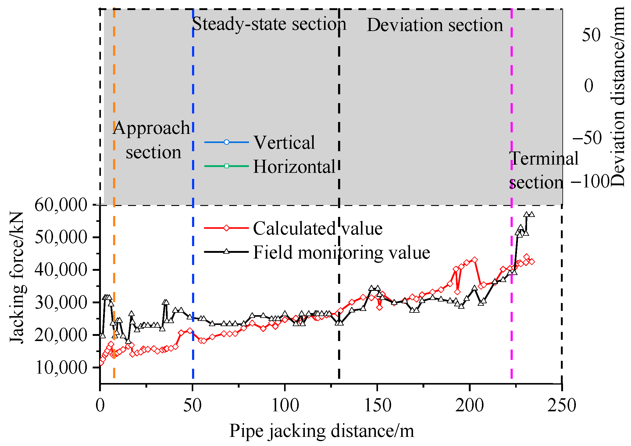
The calculated jacking force is compared with the monitoring data, as shown in
Figure 8. The total jacking force exhibits an overall increasing trend with advancing distance. Considering the development pattern of pipe jacking machine deviation and jacking force during the jacking process, the following analytical approach was adopted: during the initial 5 m jacking stage, where the jacking machine directly contacts the soil, Newton’s friction law was employed for frictional resistance calculation, with pipe–soil pressure determined using the Beerbower theory, and a friction coefficient of 0.4—corresponding to the ungrouted pipe–soil contact—was applied.
In the approach section, as the injected grout permeates through the soil, this condition deviates from assumption (2) of pipe–slurry contact. Therefore, a modified Newtonian friction law was applied, where the friction coefficient was determined through linear interpolation between the ungrouted coefficient (0.4) and the fully formed lubricant slurry sheath coefficient (0.08). During the stable and deviation sections, where complete lubricant slurry sheath formation was achieved, the jacking friction formula was implemented. The calculated jacking forces are shown in
Figure 8.
In the approach section, the observed values exhibited significant deviation from the theoretically calculated values. During the stable and deviation sections, the observed values showed smaller deviations from the theoretical values. In the terminal section, the observed values were consistently higher than the theoretical values. The largest discrepancies occurred in the approach section and the terminal section, with a maximum error of 22%. In the steady-state section and deviation section, the differences between the theoretical and measured values were relatively smaller, with a maximum error of 16%. The primary sources of these errors can be attributed to the neglect of strata heterogeneity and fluctuations in groundwater levels. However, the variation laws of the monitoring data and theoretical calculations with the jacking distance are consistent, indicating that the frictional resistance calculation method proposed in this paper has certain reliability.
4.2. Parameter Analysis
4.2.1. Influence of Foundation Reaction Coefficient
The subgrade reaction coefficient
k significantly influences the deflection deformation of rectangular pipe jacking, the deformation of the underlying soil, and the earth pressure beneath the pipe. As indicated by Equation (3), the value of k inherently reflects the physical properties of the surrounding strata. By establishing computational conditions ranging from 0.125
k to 8
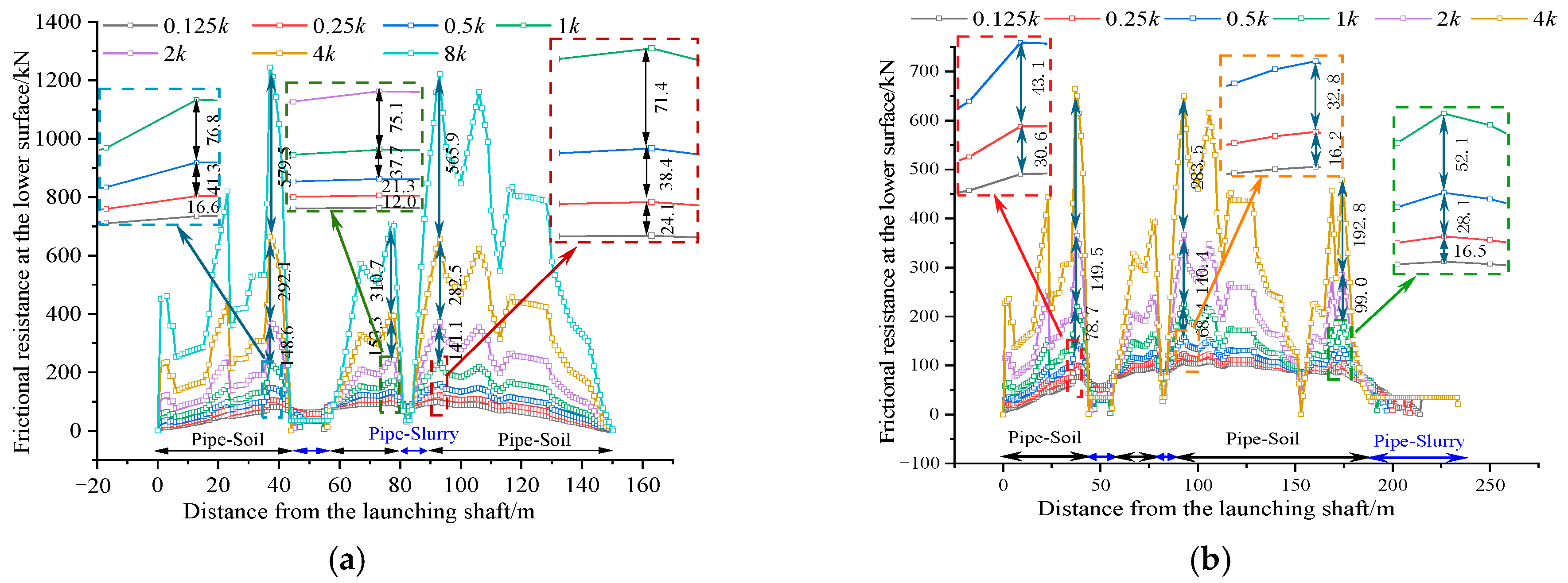
k, this study analyzes the effects of varying pipe-surrounding soil stiffness on frictional resistance, as illustrated in
Figure 9.
Figure 9 demonstrates that increasing the subgrade coefficient k not only elevates frictional resistance but also extends the pipe–slurry contact distance. As shown in
Figure 9a, doubling the k value results in an approximate 78.6% increase in the peak frictional resistance within the pipe–soil contact segment. In the pipe–slurry interaction zone, the contact pattern transitions from pipe–soil to pipe–slurry contact with increasing k values.
Figure 9b further reveals a gradual enhancement of frictional resistance in the pipe–slurry contact segment as k increases.
Notably,
Figure 9b indicates that k exerts a significantly greater influence on frictional resistance in pipe–soil contact than in pipe–slurry contact. During prolonged jacking processes, the alternating transitions between pipe–soil and pipe–slurry contact modes gradually reduce the amplification effect of
k on total frictional resistance. According to Equation (3), the
k value maintains a proportional relationship with the pipe section width
B. This implies that frictional resistance increases with pipe width
B, while maintaining a constant elastic modulus
Eb (soil modulus).
In summary, frictional resistance exhibits an increasing trend with higher k values, with k demonstrating a stronger influence on pipe–soil contact resistance than on pipe–slurry interaction. During long-distance jacking operations, the alternating contact modes between pipe–soil and pipe–slurry interfaces lead to a slight attenuation of k’s overall impact on total frictional resistance.
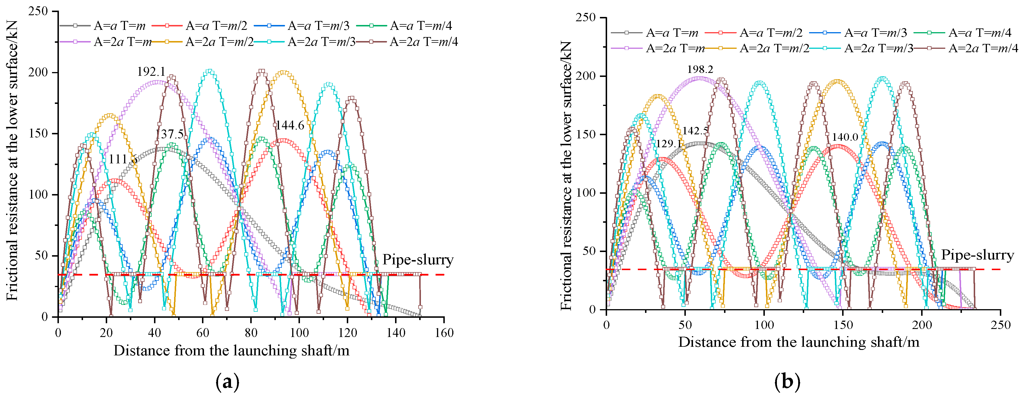
4.2.2. The Influence of the Jacking Process Deviation
Based on the analysis of pipe jacking machine deviation in
Figure 1, this study investigates the relationship between periodic parameters (amplitude and cycle) and underlying frictional resistance of rectangular pipe jacking under different jacking lengths. The computational conditions are defined with cutterhead deviation z
0 = 0, amplitudes
A =
a and
A = 2
a (where a represents the overcut clearance of the pipe jacking machine), and cycle parameter m = 2π/l (with l denoting jacking length). Preset calculation cases with amplitudes a and 2
a, combined with cycles ranging from
T to
T/4, reveal the periodic characteristics of frictional resistance, as demonstrated in
Figure 10.
Figure 10 illustrates that the variation in deviation during jacking not only alters frictional resistance but also modifies pipe–soil/slurry contact patterns. The frictional resistance exhibits periodic characteristics similar to the deviation function f(x), with 1, 2, and 3 peak resistance values observed at cycles
T = m,
T = m/2, and T = m/3, respectively.
In multi-peak scenarios, the maximum frictional resistance consistently occurs near the pipe section center. For the dual-peak case (A = a, T = m/2), the central peak reaches 144.6 kN, while in the triple-peak configuration (A = a, T = m/3), the maximum central peak measures 137.5 kN.
Under identical cycle
T conditions, increasing amplitude
A elevates frictional resistance, as shown in
Figure 10b. The peak resistance between
A =
a (
T = m) and
A = 2
a (T = m) curves increases by approximately 39.1%. Amplitude enhancement induces a transition from full pipe–slurry contact to complex pipe–soil/slurry interactions, thereby amplifying frictional resistance. A twofold increase in deviation threshold corresponds to approximately 40% growth in peak resistance.
The analysis concludes that amplitude exerts a greater influence on total jacking force than cycle parameters. Therefore, controlling deviation thresholds during jacking operations effectively reduces frictional resistance. For long-distance pipe jacking, it is recommended to implement frequent and minor steering corrections to mitigate resistance accumulation.
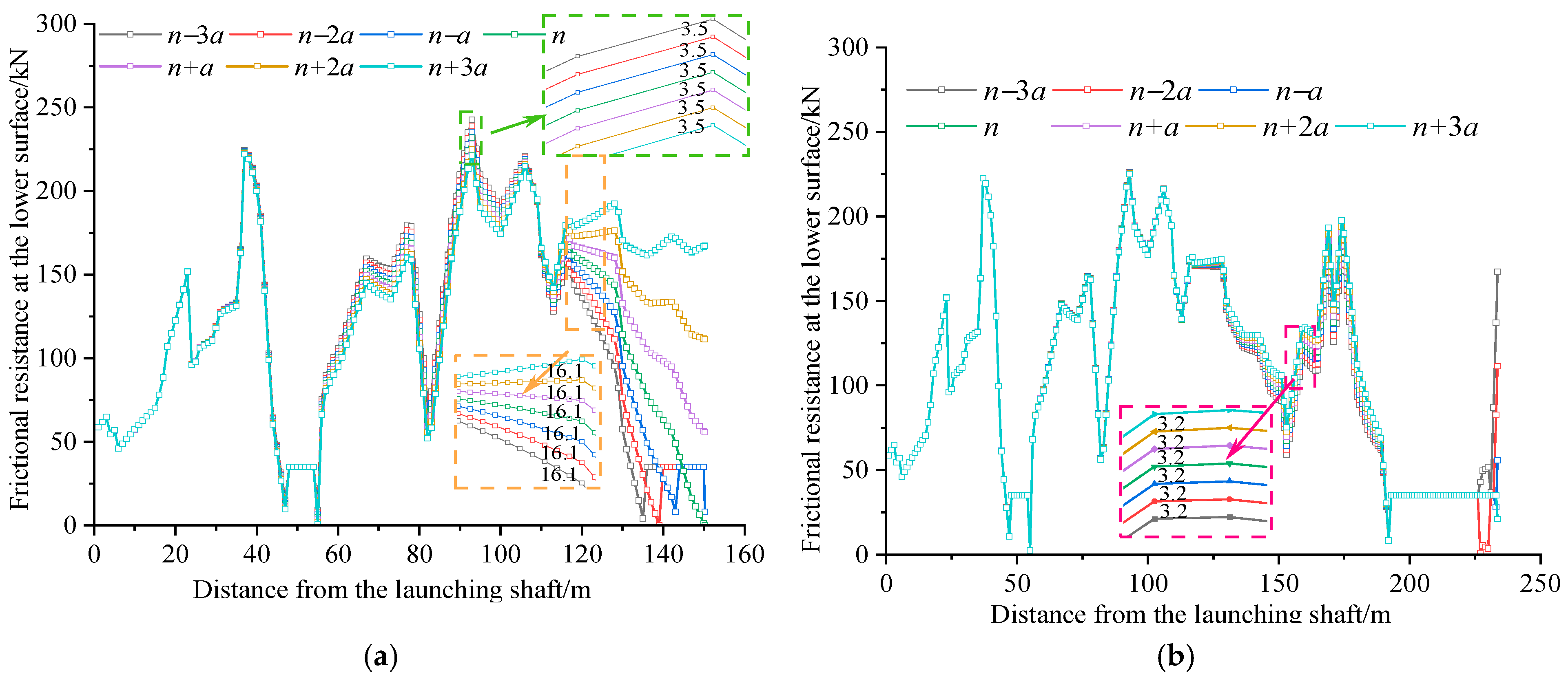
4.2.3. The Influence of Pipe Jacking Machine Deviation
A parameterized analysis of the relationship between pipe jacking machine deviation and frictional resistance was conducted by establishing working conditions with predefined deviation distances
n−i(
a), where
i = −3, −2, …, 3. Here,
n represents the field-measured deviation distance of the machine, and a denotes the overcut clearance (set as 1 cm). As illustrated in
Figure 11, increasing
i values correspond to machine deviations along the positive
z-axis direction.
Figure 11 demonstrates that progressive
z-axis positive deviations not only modify frictional resistance but also alter contact patterns. As shown in
Figure 11a, positive
z-axis deviations amplify frictional resistance in pipe–soil contact segments, with equal deviation increments inducing equivalent resistance variations. Conversely, negative
z-axis deviations near the excavation face trigger a contact pattern transition from pipe–soil to pipe–slurry. The resistance variation predominantly occurs within 90 m behind the excavation face, exhibiting distance-dependent attenuation, where proximity to the face correlates with greater resistance impacts.
Figure 11b reveals that increasing excavation distances maintain distinguishable zones of contact pattern modification and frictional resistance variation, confined within 90 m from the excavation face. Enhanced negative
z-axis deviations extend the pipe–slurry contact length within this influential zone.
Consequently, machine deviation primarily affects frictional resistance through dual mechanisms: contact pattern alterations near the excavation face and resistance magnitude variations. Progressive deviation amplifies near-face frictional resistance, establishing deviation control as a critical strategy for drag reduction during jacking operations. This underscores the operational necessity of implementing precise deviation management for effective frictional resistance mitigation.
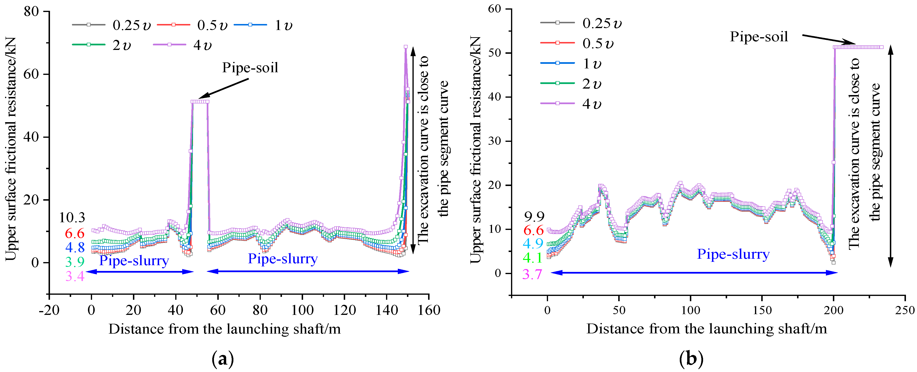
4.2.4. Influence of Slurry Viscosity
Slurry viscosity significantly influences pipe–slurry contact resistance. As revealed by previous analyses, the lower surface of rectangular pipe jacking predominantly maintains pipe–soil contact. Consequently, this study employs the frictional resistance distribution on the upper surface to investigate pipe–slurry interaction characteristics, as illustrated in
Figure 12.
Figure 12 demonstrates a positive correlation between slurry viscosity enhancement and pipe–slurry frictional resistance. As shown in
Figure 12a, incremental doubling of the viscosity coefficient induces respective resistance increases of 11.4%, 23.1%, 37.5%, and 56.1% at the pipe segment tail, indicating an accelerating effect of viscosity elevation on resistance growth.
Furthermore,
Figure 12b reveals that extended jacking distances not only amplify pipe–slurry resistance but also facilitate contact pattern transitions from pipe–soil to pipe–slurry interactions, as observed in
Figure 12a. Notably, within the convergence zone between the excavation face and pipe section profiles, a reverse transition from pipe–slurry to pipe–soil contact occurs, contributing to progressive resistance accumulation during jacking.
Collectively, slurry viscosity predominantly governs pipe–slurry interactions. However, given that pipe–slurry frictional resistance remains substantially lower than pipe–soil resistance, slurry selection during jacking operations should prioritize formation-specific filtration control requirements. This strategic approach ensures optimal grouting performance while maintaining effective frictional resistance management throughout the jacking process.
5. Conclusions
Based on the attitude monitoring data of pipe jacking machines, this study establishes an attitude prediction method for pipe jacking machines, thereby developing a calculation method for frictional resistance in long-distance rectangular pipe jacking that considers the contact patterns between the pipe and soil/slurry. The main conclusions are as follows:
- (1)
Analysis of machine deviation monitoring data reveals that axial deviation follows a sinusoidal periodic pattern, with cumulative effects of progressive deflection during prolonged jacking operations leading to sustained positive deviation trends. Short-distance jacking is dominated by angular deviations caused by machine misalignment, whereas long-distance operations exhibit complex pipe–soil/slurry contact patterns arising from the combined effects of machine deviation and pipe segment deflection.
- (2)
The subgrade reaction coefficient k significantly influences both resistance magnitude and contact patterns: a twofold increase in k induces approximately an 80% rise in peak resistance. Machine deviation generates two distinct influence zones spanning 90 m behind the excavation face: a resistance variation domain and a contact pattern transition region. Deviation amplitude exerts a more significant impact on resistance than cycle parameters—a doubling of the amplitude triggers approximately a 70% enhancement in peak resistance. Pipe–slurry contact resistance demonstrates viscosity-dependent growth, with a twofold increase in viscosity coefficients yielding a maximum resistance increase of approximately 56%.
- (3)
Although the reliability of the proposed frictional resistance calculation method was verified by comparing the actual engineering jacking force monitoring data with the theoretically calculated values, the model does not account for the inhomogeneity of the stratum or the influence of groundwater level fluctuations. Consequently, the predictive accuracy of the proposed calculation method for top force in complex, water-rich strata may be limited.
Author Contributions
Conceptualization, formal analysis, methodology, data curation, writing—original draft, X.T., Z.S. and P.M.; Writing—review and editing, X.T., K.L. and P.M.; Supervision, Z.S. and J.X. All authors have read and agreed to the published version of the manuscript.
Funding
The present work was supported by the National Natural Science Foundation of China (No. 52308375, 52178393), the China Postdoctoral Science Foundation (2024MD753967), and the Shaanxi Province Postdoctoral Science Foundation (2023BSHEDZZ273). The authors gratefully acknowledge this financial support.
Data Availability Statement
The data presented in this study are available on request from the corresponding author.
Conflicts of Interest
Author Jiangsheng Xie was employed by China Railway 20th Bureau Group Corporation Limited. The remaining authors declare that the research was conducted in the absence of any commercial or financial relationships that could be construed as a potential conflict of interest.
References
- Broere, W. Urban underground space: Solving the problems of today’s cities. Tunn. Undergr. Space Technol. 2016, 55, 245–248. [Google Scholar] [CrossRef]
- Sterling, R.L. Developments and research directions in pipe jacking and microtunneling. Undergr. Space 2020, 5, 1–19. [Google Scholar] [CrossRef]
- Liu, T.; Liu, J.; Tan, Y.; Fan, D. Prediction of Jacking Force for Construction of Long-Distance Rectangular Utility Tunnel Using Differential Evolution-Bidirectional Gated Re-Current Unit-Attention Model. Buildings 2024, 14, 3169. [Google Scholar] [CrossRef]
- Luo, Y.; Alaghbandrad, A.; Genger, T.K.; Hammad, A. History and recent development of multi-purpose utility tunnels. Tunn. Undergr. Space Technol. 2020, 103, 103511. [Google Scholar] [CrossRef]
- Chapman, D.N.; Ichioka, Y. Prediction of jacking forces for microtunnelling operations. Tunn. Undergr. Space Technol. 1999, 14, 31–41. [Google Scholar] [CrossRef]
- Kaushal, V.; Najafi, M.; Serajiantehrani, R. Environmental impacts of conventional open-cut pipeline installation and trenchless technology methods: State-of-the-art review. J. Pipeline Syst. Eng. 2020, 11, 04020047. [Google Scholar] [CrossRef]
- Li, J. Key technologies and applications of the design and manufacturing of non-circular TBMs. Engineering 2017, 3, 905–914. [Google Scholar] [CrossRef]
- Cheng, W.C.; Ni, J.C.; Shen, S.L.; Huang, H.-W. Investigation into factors affecting jacking force: A case study. Proc. Inst. Civ. Eng.-Geotech. Eng. 2017, 170, 322–334. [Google Scholar] [CrossRef]
- O’Dwyer, K.G.; Mccabe, B.A.; Sheil, B.B. Interpretation of pipe-jacking and lubrication records for drives in silty soil. Undergr. Space 2020, 5, 199–209. [Google Scholar] [CrossRef]
- Milligan, G.W.E.; Norris, P. Pipe-soil interaction during pipe jacking. Proc. Inst. Civ. Eng.-Geotech. Eng. 1999, 137, 27–44. [Google Scholar] [CrossRef]
- Han, J.; Wang, F.; Al-Naddaf, M.; Xu, C. Progressive development of two-dimensional soil arching with displacement. Int. J. Geomech. 2017, 17, 04017112. [Google Scholar] [CrossRef]
- Deng, Z.; Liu, X.; Zhou, X.; de la Fuente, A.; Han, Y.; Xiong, F.; Peng, H. Field monitoring of mechanical parameters of deep-buried jacketed-pipes in rock: Guanjingkou water control project. Tunn. Undergr. Space Technol. 2022, 125, 104502. [Google Scholar] [CrossRef]
- Terzaghi, K.T. Theoretical Soil Mechanics; John Wiley & Sons: Hoboken, NJ, USA, 1943. [Google Scholar]
- Ye, Y.; Peng, L.; Zhou, Y.; Yang, W.; Shi, C.; Lin, Y. Prediction of friction resistance for slurry pipe jacking. Appl. Sci. 2020, 10, 207. [Google Scholar] [CrossRef]
- Liu, W.; Liang, J.X.; Xu, T. Tunnelling-induced ground deformation subjected to the behavior of tail grouting materials. Tunn. Undergr. Space Technol. 2023, 140, 105253. [Google Scholar] [CrossRef]
- Liang, J.X.; Liu, W.; Yin, X.S.; Li, W.; Yang, Z.; Yang, J. Experimental study on the performance of shield tunnel tail grout in ground. Undergr. Space 2025, 20, 277–292. [Google Scholar] [CrossRef]
- Ma, P.; Shimada, H.; Sasaoka, T.; Hamanaka, A.; Moses, D.N.; Dintwe, T.K.; Matsumoto, F.; Ma, B.; Huang, S. A new method for predicting the friction resistance in rectangular pipe-jacking. Tunn. Undergr. Space Technol. 2022, 123, 104338. [Google Scholar] [CrossRef]
- Ye, P.; Lan, B.; Zhang, P.; Zeng, C.; Xu, T.; Xu, Y.; Wu, R. Numerical Simulation Study on Evolution Process of Carrying-Soil Effect of Rectangular Pipe Jacking. Buildings 2024, 14, 3057. [Google Scholar] [CrossRef]
- Pellet-Beaucour, A.L.; Kastner, R. Experimental and analytical study of friction forces during microtunneling operations. Tunn. Undergr. Space Technol. 2002, 17, 83–97. [Google Scholar] [CrossRef]
- Li, X.G.; Yuan, D.J. Response of a double-decked metro tunnel to shield driving of twin closely under-crossing tunnels. Tunn. Undergr. Space Technol. 2012, 28, 18–30. [Google Scholar] [CrossRef]
- Meskele, T.; Stuedlein, A.W. Static soil resistance to pipe ramming in granular soils. J. Geotech. Geoenviron. 2015, 141, 04014108. [Google Scholar] [CrossRef]
- Peerun, M.I.; Ong, D.E.L.; Desha, C. A strategic review on enhanced DEM simulation and advanced 3-D particle printing techniques to improve pipe-jacking force prediction. Tunn. Undergr. Space Technol. 2022, 123, 104415. [Google Scholar] [CrossRef]
- Ji, C.L.; Zhang, X.; Ni, F.J. Pipe-soil contact state and jacking force prediction of rectangular pipe jacking. J. Northeast. Univ. (Nat. Sci.) 2020, 41, 1459–1464. [Google Scholar] [CrossRef]
- Ji, X.; Zhao, W.; Ni, P.; Barla, M.; Han, J.; Jia, P.; Chen, Y.; Zhang, C. A method to estimate the jacking force for pipe jacking in sandy soils. Tunn. Undergr. Space Technol. 2019, 90, 119–130. [Google Scholar] [CrossRef]
- Rong, L.; Yang, H.J. Attitude control technology for super-large cross-section rectangular pipe-jacking machine: Case study on tunneling crossing underneath Zhongzhou Avenue in Zhengzhou. Tunn. Constr. 2015, 35, 1097–1102. [Google Scholar]
| Disclaimer/Publisher’s Note: The statements, opinions and data contained in all publications are solely those of the individual author(s) and contributor(s) and not of MDPI and/or the editor(s). MDPI and/or the editor(s) disclaim responsibility for any injury to people or property resulting from any ideas, methods, instructions or products referred to in the content. |
© 2025 by the authors. Licensee MDPI, Basel, Switzerland. This article is an open access article distributed under the terms and conditions of the Creative Commons Attribution (CC BY) license (https://creativecommons.org/licenses/by/4.0/).


