Article

Stability Analysis of Removal of Steel Supports in Variable-Section Pits

1
Communications Construction Company of CSCEC 7th Division Co., Ltd., Zhengzhou 450004, China
2
College of Transportation, Jilin University, Changchun 130012, China
*
Author to whom correspondence should be addressed.
Buildings 2025, 15(11), 1903; https://doi.org/10.3390/buildings15111903
Submission received: 10 March 2025 / Revised: 14 April 2025 / Accepted: 25 May 2025 / Published: 31 May 2025
(This article belongs to the Special Issue Intelligent Design, Green Construction, and Innovation)

Abstract

In order to analyse the changes in pit stability caused by the removal of steel support and solid casting of a variable section pit, this paper carried out the whole process of numerical simulation of the selected section pit construction using ABAQUS, introduced a redundancy evaluation method based on the growth rate of deformation, calculated the stable state of the supporting structure, assessed the de-supporting state under two de-supporting design schemes—laminar and stepped—and carried out the stability analysis of the two schemes. Finally, the characteristics of pit stability changes under the state of de-supporting in the variable cross-section area were obtained. The results show that the stepped backfill and de-propping scheme provides better stability control than the laminated scheme, the minimum redundancy Rmin in the key variable section area increases by 0.03 on average, the minimum relative deformation Pmin decreases by 5% on average, and the maximum local improvement is 10.52%. The stepped scheme shows the most significant improvement in redundancy at the distal end of the reduced section, and the overall deformation response is more homogeneous. The study verifies the applicability of the redundancy analysis method in evaluating variable cross-section pit bracing, which is of great engineering significance for the optimisation of pit bracing design under similar structural conditions.

1. Introduction

The scale of foundation pit engineering is gradually increasing with the continuous expansion of urban underground spaces. Due to the dense building layouts and complex geological conditions in cities, the problem of deep foundation pit support removal has gradually become the focus of the engineering field. In the research and design of foundation pit engineering, people mainly focus on the deformation of the support structure during the excavation of the foundation pit, but the effects of support removal are often neglected [1,2]. However, actual engineering experience shows that the maximum deformation of a deep foundation pit support structure does not occur in the excavation stage but in the support removal stage [3,4,5].
As an important part of the internal support system, steel support plays a key role in balancing soil pressure, controlling deformation, and ensuring the overall stability of the structure during foundation pit construction. The steel support removal stage is usually the most sensitive and critical stage of pit deformation [6]. After the gradual removal of the support, the force and deformation state of the enclosing structure in the pit, such as the diaphragm wall, will change significantly, and horizontal displacement or locally intensified deformation may occur in some areas after the removal of the support, adversely affecting the overall stability. Furthermore, the continuity of the support system will break and the reduced stiffness of its components will increase the variation in the response of the soil body after unloading [7]. Scholars have carried out a series of studies on the deformation effects of the pit during the steel support removal stage, mainly focusing on deriving the deformation calculation formula of the pit in each stage [8,9], analysing the field monitoring data to derive the deformation change rule of the pit during the stage of dismantling the support [10,11], and proposing support dismantling technologies [12,13,14,15]. However, the evaluation of the stability of the pit during the internal support dismantling process and the influence of different dismantling procedures have not been studied in detail.
In previous research on the foundation pit support structure, the setup conditions for the support structure redundancy system research are similar to those for the internal support removal stability evaluation research [16,17,18]. The core idea of redundancy design is to reduce construction risks by reserving a certain safety margin to enhance the resilience and adaptability of the support structure. At present, several scholars have carried out extensive research on the redundancy of foundation pit support and put forward a variety of redundancy assessment models and optimisation methods [19,20,21]. In actual engineering, the structural design is usually based on the ultimate load-carrying capacity of the structure; hence, redundancy calculation methods that use the rate of loss of load-carrying capacity as the evaluation index are common in the stability analysis of pit support structures [22]. Nevertheless, the calculation process for this method is highly complicated, making it challenging to address an asymmetric structural system with a large number of bars [23,24,25,26]. Accordingly, several scholars have simplified the redundancy calculation formula based on the loss rate of bearing capacity and developed a redundancy calculation formula based on the deformation growth rate. This formula is used as a basis for comparing the stability of two structural systems in different local failure states, making the redundancy calculation process for comparative analysis easy and practical [13,27].
In view of the current pit stability research situation that focuses mostly on constant cross-section pits and less on the stability problems during the dismantling and bracing stage, this paper selects a representative variable cross-section pit as the research object, establishes the ABAQUS finite element numerical model for the entire construction process, introduces a redundancy evaluation method based on the growth rate of deformation, and compares and analyses the two kinds of backfilling and dismantling and bracing schemes—laminar and stepped—thereby systematically analysing the stability of pits from excavation to dismantling and bracing. The stability change in pit support structure during the entire process of backfilling was systematically analysed from excavation to backfilling, and the change characteristics of various indexes of the variable-section pit and the preferred option among the two backfilling and dismantling schemes were finally obtained, which provided theoretical support and engineering reference for the optimisation of the design and construction of pits under similar complex working conditions.

2. Project Overview and Finite Element Model Construction

2.1. Project Overview

This paper takes the underground structure of the Donglong interval (Donghu Town Station to Longjia Airport Station) as the engineering background and selects the left line K63+615 to K63+695 in the No. 1 cut-and-cover section—a portion with a large change in cross-section—as the object of stability analysis for the demolition of the steel support of the variable cross-section foundation pit. According to the geological investigation report and construction drawings of the enclosure structure for of the selected section, the geotechnical stratification from top to bottom is powdery clay, mudstone, and conglomerate, respectively. Although ABAQUS usually simulates under homogeneous and isotropic conditions in most studies, to account for the non-homogeneous characteristics of the soil layers in the actual foundation pit, the physical and mechanical parameters of different soil layers are individually applied in the model, which is calibrated using data from on-site investigations, so that the stability of steel support removal in variable-section foundation pits can be analysed. This calibration helps overcome the limitations of the software by simplifying the assumptions to a certain extent. The enclosure structure adopts a drilled pile structure with a pile diameter of 600 mm and pile spacing of 1000 mm, and in the simulation, the drilled piles are simplified to the corresponding height and thickness of the C30 concrete ground connecting wall, with the bottom of the wall resting on the conglomerate layer. The crown beam adopts a reinforced concrete structure, and the crown beam is made of C30 concrete. The foundation pit adopts two steel supports, whose specifications are Ø609 mm (t = 16 mm) and Ø800 mm (t = 16 mm). The first steel support is supported on the crown beam, whereas the rest of the steel support is supported on the drilled piles using a double-spliced 40b horizontal steel purlin. The material used is Q235B steel, which is simplified to the corresponding cross-section size of the beam unit in the simulation. The solid poured structure mainly consists of C30 concrete, with some sections also incorporating C15 and C20 concrete layers.

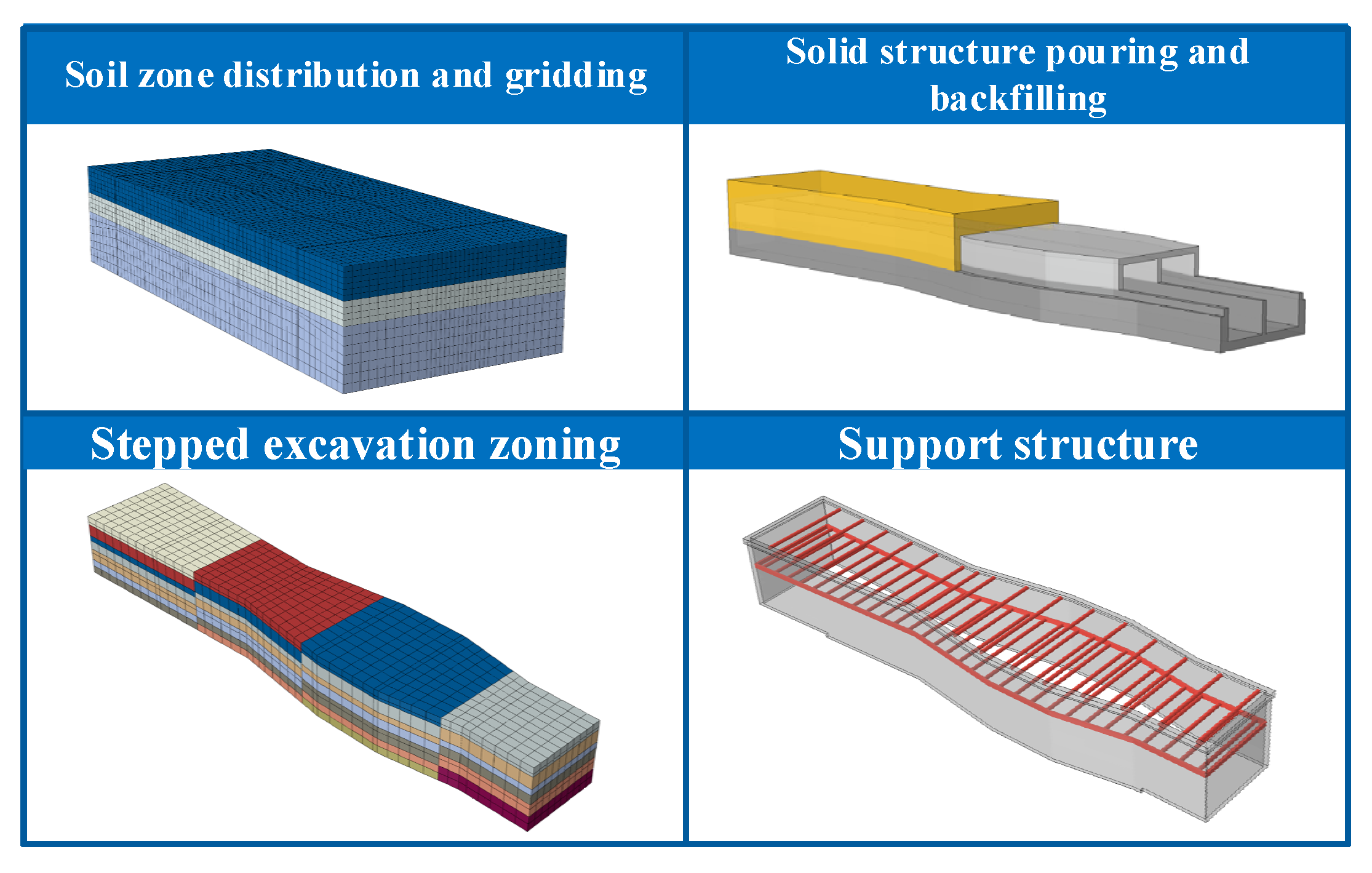
2.2. Finite Element Modelling

Numerical simulation technology provides strong support for the removal of internal support. Numerical simulation of the nonlinear deformation of the pit support and the surrounding soil can efficiently and accurately reproduce the spatial and temporal characteristics of the forces and deformations in the components of the complex engineering system so as to study the effects of different removal schemes and sequences, as well as the control parameters of the demolition on the overall stability of the pit and the deformation of the diaphragm wall. In previous studies, numerical simulation has proven to be an important tool for assessing the safety of demolition support, and some researchers have used professional software such as ABAQUS(version number: 2020HF5) to simulate stress distribution and deformation patterns under different working conditions. This virtual experiment method not only reduces costs but also significantly shortens the research and development cycle.
During the process of pit excavation and demolition support backfilling, the support structure adopts multi-pivot row pile support system combined with an external precipitation scheme. Because of anti-drainage engineering, the groundwater level can be significantly reduced, and the soil body remains in a state of sufficient drainage. As a result, the pore water pressure and seepage effect on the stability of the pit are minimal. The stability of the pit is mainly controlled by mechanical loading. Thus, the influence of the seepage field is not taken into account in the numerical simulation at this stage.
In the numerical simulation, the geometric model is constructed according to the construction drawings of the enclosure structure. The Mohr–Coulomb plasticity model is adopted to simulate the soil layer around the foundation pit due to its theoretical intuitiveness, readily obtainable parameters, computational efficiency, and extensive engineering validation, thereby effectively capturing soil shear failure mechanisms (e.g., sliding and plastic deformation) while serving as a benchmark for stability analysis in deep excavations and slope engineering, with a balance of practicality and reliability. The steel and concrete members were simulated using an elasticity model. The contact between the crown beams, ground connecting wall, and soil body is normal hard contact and tangential friction contact with a friction coefficient of 0.3. The contact between the steel support, steel purlins, crown beams, and ground connecting wall is binding. The contact between the backfill of the solid casting structure level and the soil body is also binding. The method of soil excavation and erection of crown beam, ground connecting wall, and steel support is the life-and-death cell method. The analysis includes a geostress analysis step used for geostress equilibrium and a static universal analysis step used for life-and-death cell operations, such as excavation, support, solid casting, and unloading of the braces. The type of the mesh delineation cell is C3D8R.
When determining the grid size, the grid was gradually refined and calculations were run for verification until the magnitude of change in the maximum stress after the first step of excavation of the foundation pit gradually reduced and stabilised. The final soil grid size was determined to be 5, the grid size of the crown beams and ground connecting walls to be 1, the grid size of the steel supports and steel purlins to be 2, and the grid size of the solid structure and overburden backfill to be 2.
According to the excavation plan of “longitudinal section, vertical layering, first support and then excavate” for the No. 1 open excavation section of the Donglong interval, the foundation pit of the selected section of the model is divided into 4 sections longitudinally and 7 layers vertically for stepwise excavation. A total of 19 analysis steps are established sequentially for stepped excavation and support in order to carry out excavation stage calculation, and the support state corresponding to the completion of the last steel support erection is the stable state of the support structure.
The geometrical construction of each component in the model is shown in Figure 1.
The soil layer parameters are shown in Table 1, the specific parameters of the support structure material are illustrated in Table 2, and the analysis step setup for the support structure steady state calculation is presented in Table 3.

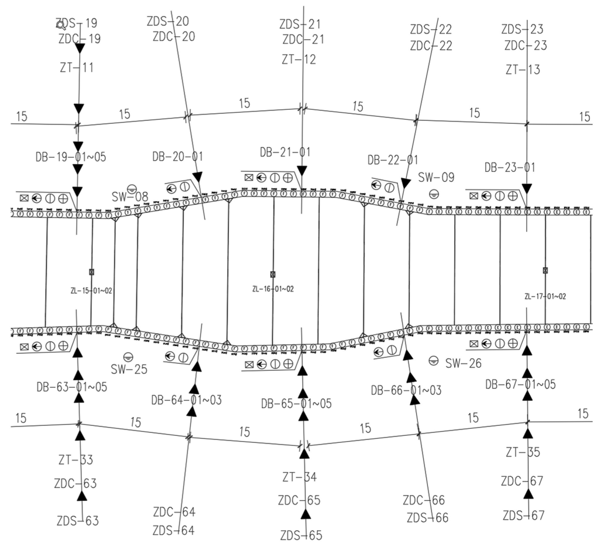
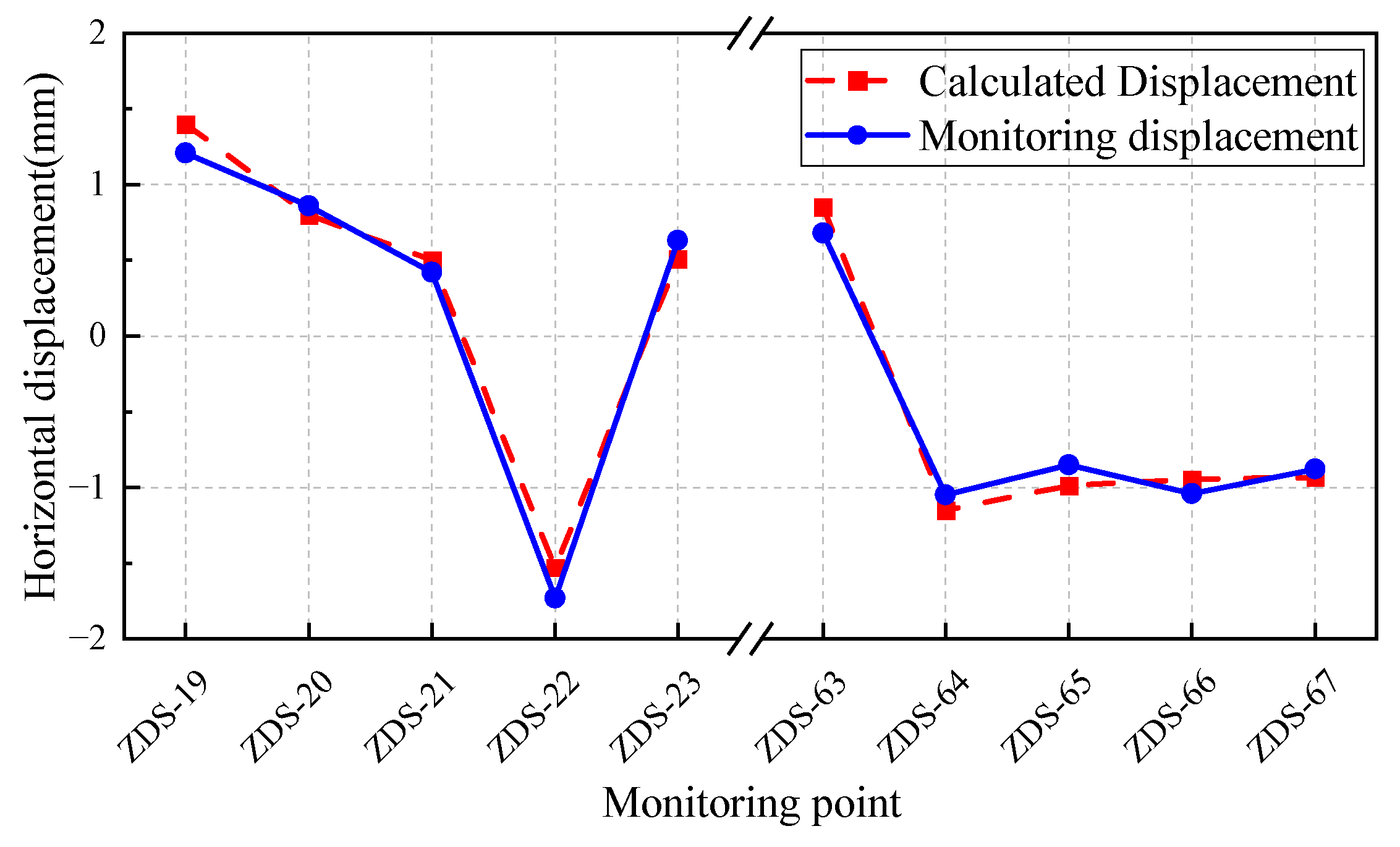
2.3. Finite Element Model Validation

In order to verify the reasonableness and error range of the finite element model, the horizontal displacement data of the top of the foundation pile in the stable state of the support structure after excavation are selected and compared with the finite element calculation results for the corresponding locations, and five monitoring points—ZDS-19, ZDS-20, ZDS-21, ZDS-22, and ZDS-23—are taken as the objects of analysis. The numbered locations of these monitoring points are shown in Figure 2, and the horizontal displacement detection results and finite element calculation results for the selected points are shown in Figure 3.
A comparative analysis of the finite element calculation results and the field monitoring data shows that the two have high consistency in value and direction. The average absolute error of each measurement point is 0.125 mm, and the average relative error is 13.70%. The displacement direction of all monitoring points is consistent with the finite element calculation results, and there is no positive or negative directional error, which indicates that the model is reasonable in terms of its physical mechanism, load transfer path, and constraint setting, and it effectively reflects the actual structural force and deformation trend. Therefore, the finite element model has good accuracy and engineering applicability, and the calculation results basically meet the requirements of civil engineering for a displacement error of less than 15%. Thus, the model can be used for the stability analysis of the following two schemes.

3. Demolition Support Scheme Design

In the actual project, the backfill and dismantling process involved in unloading includes five stages: solid casting of the bottom slab, removal of the lower steel support, solid casting of the top slab, removal of the upper steel support, and backfilling of the overburden. The order of removal of the steel support, the sequence of solid casting, the sequence of overburden backfilling, and the form of cross-sectional changes will largely affect the overall stability of the pit in the process of dismantling and unloading of the bracing.

3.1. Steel Support Numbering

The 46 steel supports in the variable-section pit are numbered to facilitate the design of the demolition support scheme, the analysis step setting, and the redundancy analysis during the demolition stage. The steel supports are numbered from bottom to top and from left to right, such as ‘1–15’, indicating the 15th steel support from left to right on the lower layer. However, during the demolition stage, the numbering is based on the variable cross-section areas, the number of floors, and their location in the area of numbering. This area is divided into five sections from left to right, namely, contraction section, expansion section, constant section, contraction section, and constant section. For example, ‘C2103’ indicates the third steel support from left to right in the lower layer of the expansion section. The number of steel support indicates its position in the entire foundation pit and is highly useful when analysing the axial force. The number of the dismantling stage indicates the support’s position in the area of the variable section to which it belongs. This is particularly intuitive and convenient during analysis. The corresponding positions of the steel supports and their numbers are shown in Figure 4.

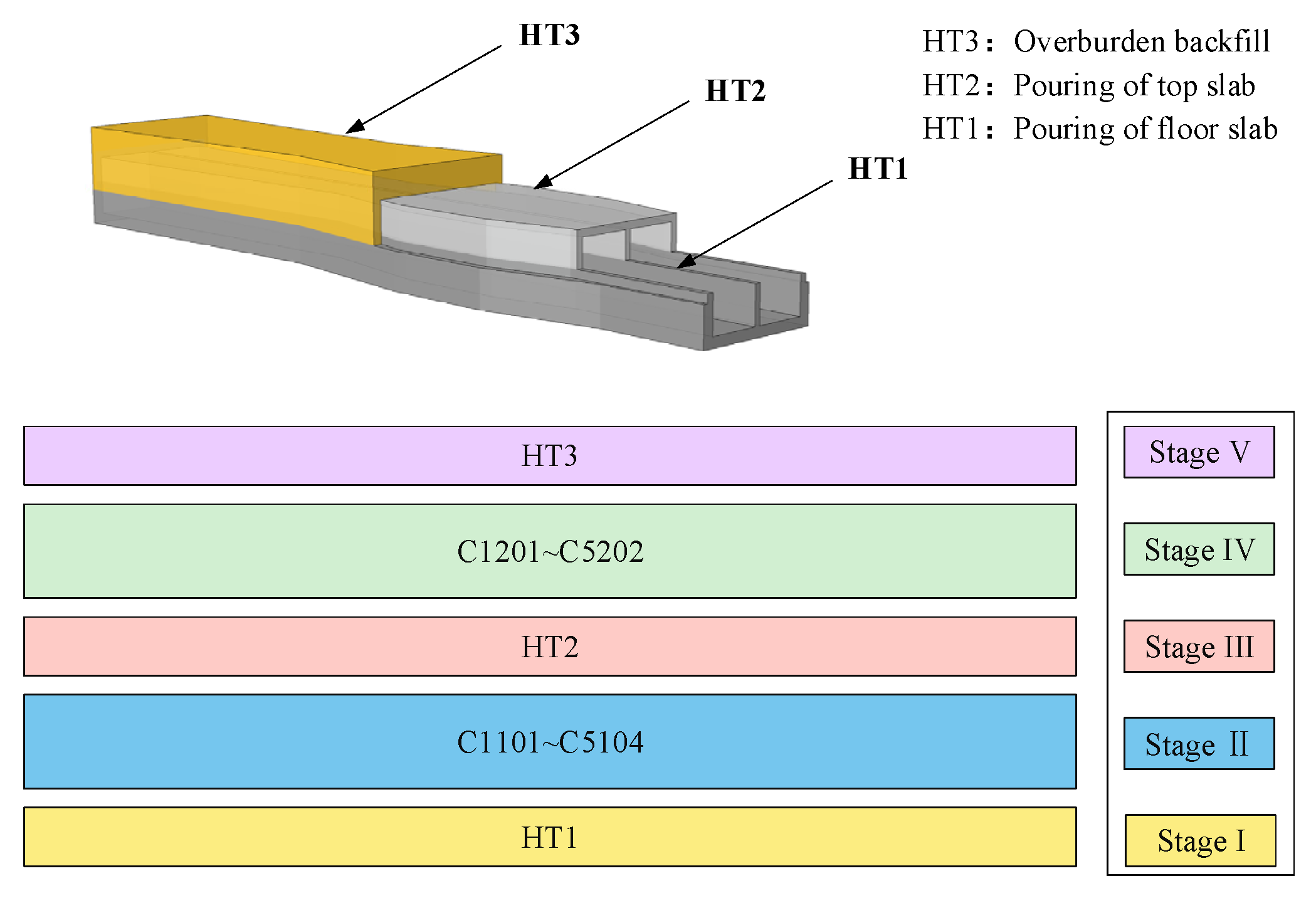
3.2. Layered Backfill and De-Bracing Programme

In the actual project, the backfilling and de-supporting processes in a certain section include the following steps: solid pouring of the bottom slab, removal of the lower steel support, solid pouring of the top slab, removal of the upper steel support and backfilling of the overburden. Given that poured concrete requires a specific curing time to gain strength, the design of the backfilling and de-bracing process, taking into account the time control, must focus on the timing and execution of the solid pouring process for each layer. The layered backfilling and removal of support scheme involves performing the pouring process for the same layer across the entire pit at the same time. This approach saves time and at the same time maximises the impact of the bottom slab pouring on the lower layer of support removal and the top slab pouring on the upper layer of support removal. In the analysis of the stability of different cross-sections of the steel support removal, the consistent backfilling progress allows for a more concise comparative analysis between the different cross-sections of the region. The specific construction process is shown in Figure 5.

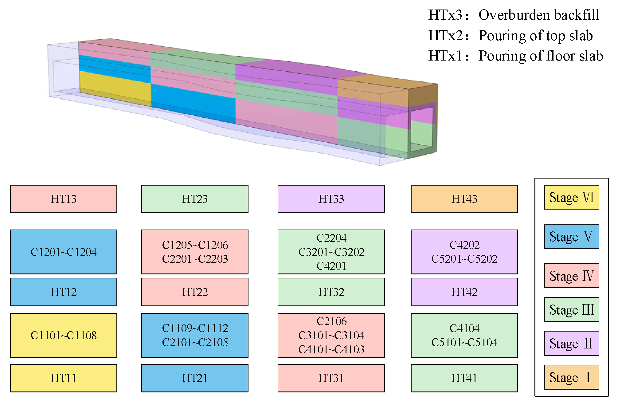
3.3. Stepped Backfill and De-Bracing Programme

In foundation pit construction, the first step to carry out solid pouring is to set up the formwork, which can be labour-intensive for foundation pits that cover a large area. Therefore, a backfilling and bracing process is required to reduce the working surface, ensure efficiency, and improve the stability of the bracing. The stepped backfill and de-propping scheme retains the length of the working surface as much as possible while exerting the influence of solid casting and overburden backfill on de-propping at each stage. The factors to be considered in the comparative analysis are also highly complicated because the de-propping status of different sections is not the same when stability analysis is carried out. The specific construction process is shown in Figure 6.

3.4. Supplementary Finite Element Model Analysis Steps for the Disassembly and Bracing Stage

The geometrical model of solid casting and backfilling has already been established during the preliminary construction of the finite element model. Accordingly, subsequent analysis steps must be added in accordance with the above-mentioned de-bracing scheme to carry out the calculation of the de-bracing stage. A total of 68 analysis steps were obtained by removing 46 steel supports one by one according to the design scheme of laminated backfill and unbracing. Meanwhile, 58 analysis steps were obtained by removing 46 steel supports one by one according to the scheme of stepped backfill and unbracing. The layer backfill and removal of bracing as well as step backfill and removal of bracing analysis step settings are shown in Table 4 and Table 5.

4. Stability Analysis of Layered Backfill and Demolition Support Design Options

4.1. Sedimentation Analysis

The 11 points on the settlement analysis path shown in Figure 7 are taken to analyse the surface settlement, and the selected points are located directly above steel supports 1–20. The main stages in which the settlement values change are the stable state of the support structure (E10), the bottom slab casting (HT1), the removal of the upper layer of the steel supports (C3102), the top slab casting (HT2), the removal of the lower layer of the steel supports (C3201), and the overlaying backfill (HT3). These settlement values along the analysed path for each stage are shown in Figure 8.
In the pit with a small preloaded axial force, the surface vertical displacement of the stable state of the supporting structure should be as follows due to the excavation unloading effect: the edge of the pit slightly bulges and gradually decreases to zero with an increase in the distance from the edge of the pit. In the selected section of the pit analysed in this work, the peak position of the bulge value of the stable state of the supporting structure (E10) shifted towards the edge of the pit at a point of 3–4 m due to the large preloaded axial force of the steel support.
In the backfilling and bracing removal stage, the settlement curves for each bracing removal step showed the following characteristics: the settlement value increment due to C3102 was 0.6 mm; the settlement value increment due to C3101 was only 0.05 mm; the cumulative effect of the removal of a significant number of lower steel braces existed between HT2 and C3102, whose settlement value increment was 0.6 mm; the settlement value increment due to HT1 was less than 0.05 mm; the settlement value increment due to HT3 was less than 0.05 mm; the settlement value increment due to HT1 was more than 0.6 mm; the effect of the support axial force formed in HT3 on the area outside the edge of the foundation pit was greater than the effect of vertical loading, and the settlement value was greatly reduced (about 0.5 mm); and the change in the settlement value of the soil in contact with the through-beam was less than 0.05 mm. Accordingly, we deduced the following: (I) the unloading of the foundation pit, loading of the internal support axial force, and backfilling of overburden reduce the settlement value of the soil around the foundation pit, and a regional bulge is observed when the effect is significant; (II) an increase in the pre-loaded axial force results in an increase in the vertical component of the support axial force, which in turn increases the settlement value of the surrounding soil when the support is removed; (III) vertical loading of the foundation pit increases the settlement value of the surrounding soil; (IV) friction of the concrete support with the soil minimises the change in the settlement value of the soil around the foundation pit.

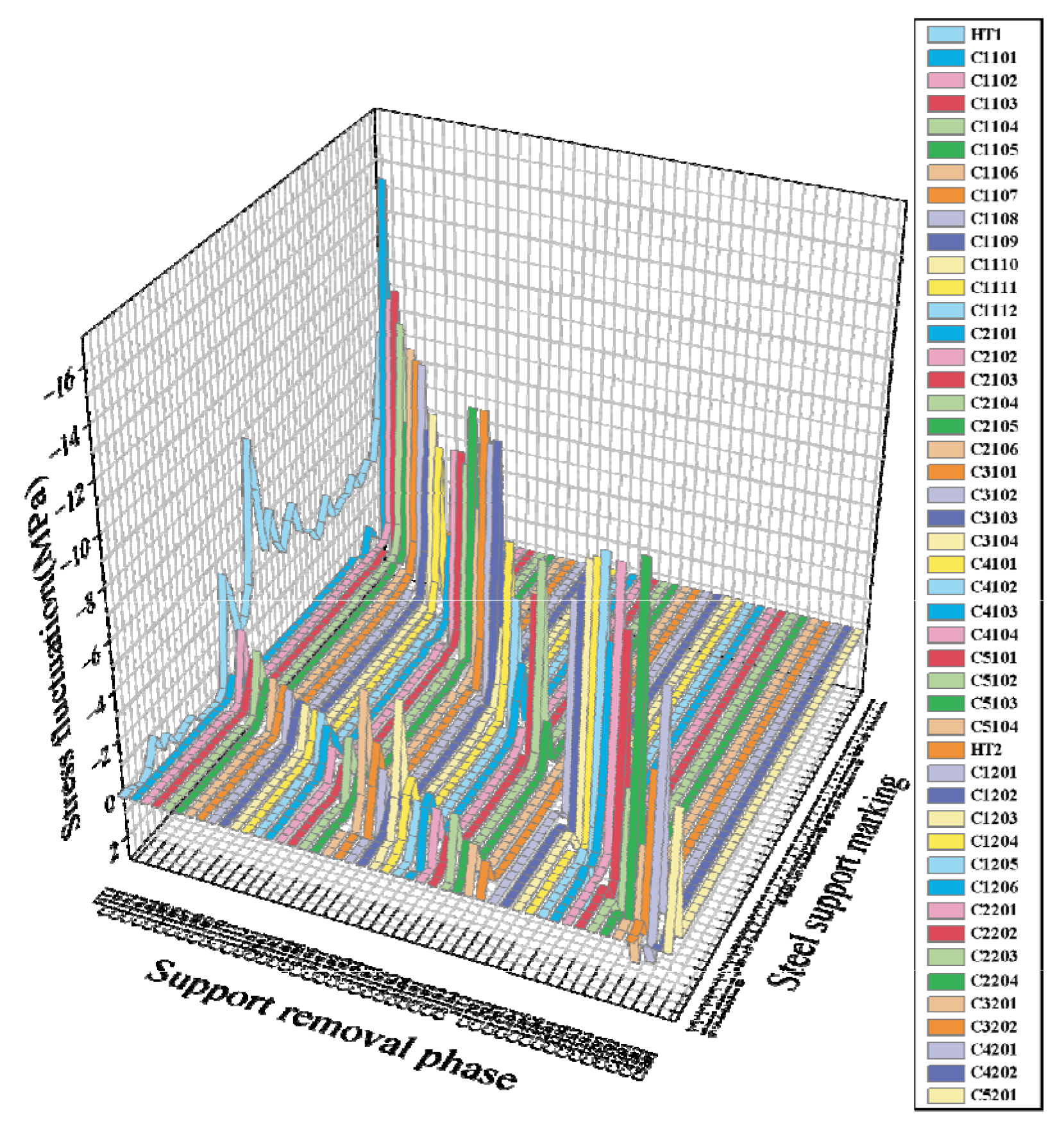
4.2. Axial Force Analysis

When carrying out the axial force analysis for the unsupported state, the fluctuating area of the axial force of the steel support caused by backfilling and support removal is observed, along with the amplitude of fluctuation and the trend of the axial force at each stage of support removal. This helps obtain the transmission path of the axial force of the steel support after its removal, the range of the fluctuation of the axial force, and the key factors influencing the sudden change in the axial force [28,29,30]. In the variable-section foundation pit, the main factors to determine the axial force value of the steel support are lateral earth pressure, preloaded axial force, and soil deformation due to unloading. During excavation, the lateral earth pressure is related to the depth of the steel support arrangement. The preloaded axial force is related to the length of the steel support. Meanwhile, the soil deformation due to unloading is related to the width of the pit section and excavation depth. Accordingly, in the pit structure with a constant excavation depth, the key influencing factors that affect the value of the axial force of the steel support in the stable state of the supporting structure are as follows: section width, arrangement depth, and the setting method of the preloaded axial force. The axial force value of the steel support in the stable state of the supporting structure (E10) is shown in Figure 9. The trend of the axial force value in each stage is basically in line with the expectations (i.e., the stress value of the steel support increases with an increase in the depth of the arrangement, the width of the cross-section, and the preloaded axial force). However, some features are the result of the cross-coupling effect of the various factors. For example, the stress value of the steel support near the ports suddenly increases due to the torsion of the pit corner caused by the absence of corner braces at the two ends of the pit. No significant change is observed in the stress value of the steel support at the corresponding position due to the insignificant change in the width of the contraction section. A sudden change in the stress is observed at the junction between the contraction section and the expansion section of the steel support in the upper layer due to the expansion of the top of the narrow section caused by unloading.
In the unbracing stage, when analysing the results of the steel brace cross-section stress calculation of 46 steel braces across 49 analysis steps, direct examination of the steel brace stress itself, to determine the influence of each stage of unbracing on the axial force of the steel brace, is challenging. Accordingly, this work takes the variation in the cross-section stress of the steel support in each stage as the research object to analyse the fluctuation area and amplitude of the steel support axial force. The stress fluctuation diagram (Figure 10) demonstrates that the axial force fluctuation range of the bottom slab casting stage includes the whole pit interval. The axial force fluctuation value of the lower steel support is larger than that of the upper steel support. The peak fluctuation occurs at the two ends of the pit, where the lower steel support is located, with a fluctuation amplitude of −8.84 MPa. The fluctuation of axial force in the middle section of the pit is more stable, and the fluctuation intervals of the steel support in the middle section of the lower level and the section position of the upper level are −2 MPa~−6 MPa and −0.3 MPa~−1.1 MPa, respectively. The fluctuation of axial force at the remaining locations is stable, with the fluctuation amplitude of the lower and upper steel supports ranging −2 to −6 MPa and from −0.3 MPa to −1.1 MPa, respectively. The fluctuation range of the axial force of roof slab pouring includes only the upper steel support, and the fluctuation peak is only −1.24 MPa; the fluctuation range of the axial force of the rest of the dismantling support stage includes only the two to three steel supports immediately adjacent to the dismantling steel support. When the lower steel support is dismantled, the two to three upper steel supports immediately adjacent to the dismantling steel support are included, with fluctuation peaks appearing in both the lower steel support and the upper steel support. The peak fluctuation appears in the steel support closest to the one being removed, while the fluctuation amplitude of the steel support in the rest of the fluctuation range is close to zero.
The peak value of stress fluctuation is shown in Figure 11. When the lower steel support is removed, its axial force fluctuation amplitude is large. The fluctuation trend of the peak value is related to the width of the cross-section, whereas the fluctuation amplitude of the axial force of the upper steel support is small and stable. In the case of the removal of the upper steel support, the fluctuation amplitude of the axial force steadily increases in the same section, and it substantially decreases when crossing the cross-section area. The following conclusions are drawn: When the lower steel support is removed, the main force transmission path is transverse, the secondary force transmission path is vertical, and the force transmission mode is the extension of the deformation of the ground-connected wall; when the upper steel support is removed, the deformation expansion caused by the support’s removal is curbed only at the cross-section intersections. After reaching the cross-section intersections, the steel support stresses are dissipated by the deformation of the ground-connected wall.

4.3. Redundancy Analysis

From the settlement and axial force analysis, it can be seen that due to the multi-factor coupling effects, the settlement value characteristics are not obvious, making it difficult for the settlement value at each stage to reflect the stability of the corresponding stage of pit support. Similarly, due to variations in deformation constraints of the different paths and fluctuations, the axial force of the steel supports after their removal cannot reflect the overall status of the pit support. The settlement and axial force values of the steel support cannot reliably characterise the stable state throughout the entire dismantling stage. In the entire process of dismantling support, the deformation of the inner wall of the pit always reflects the settlement characteristics of the soil around the pit and the fluctuation characteristics of the axial force of the steel support to a certain extent. The stability of the pit can be evaluated during the support dismantling stage, when the structure has no steel support. Accordingly, this work adopts the stiffness redundancy of the supporting structure to characterise the stability of each support removal stage and compare the stability differences between different support removal schemes [31,32]. The expression for stiffness redundancy based on the deformation growth rate is as follows:
R = S 0 S C S 0 ,
where S0 is the deformation maximum value of the supporting structure in the stable state, and SC is the deformation maximum value of the supporting structure in the dismantling state. The redundancy calculation method demonstrates that the smaller the change, the larger the redundancy value, and the larger the change, the smaller the redundancy value, which is positively correlated with the safety reserve of the supporting structure. When the redundancy value calculated is greater than 1000, the change in the maximum value of deformation is less than one-thousandth of the maximum deformation in the stable state of the supporting structure. At this point, the change in the safety reserve is small and can be ignored.
The relative deformation is taken as the reference quantity of redundancy to extensively understand the practical significance of redundancy. The factor is calculated using the following formula:
P = S C S 0
The redundancy values R and their corresponding relative deformations P for each variable-section region at each stage of unbracing are shown in Figure 12.
The R–P diagram of the layer backfill and strut removal demonstrates that the redundancy R and relative deformation P have the following characteristics: A negative R value area indicates an increment in deformation reserve; the smaller the increment, the larger the value. A positive R value area indicates the residual amount of the deformation reserve; the larger the residual amount, the larger the value. A positive P value area indicates that the direction of S0 is the same as that of SC, while a negative value area denotes that the direction of S0 is the opposite of that of SC. The absolute value of redundancy R follows the same trend of change as the relative deformation P. When the variation interval of the maximum value of deformation is small, the response of redundancy R is sensitive; when the variation interval of the maximum value of deformation is large, the relative deformation P efficiently reflects the trend of change in the deformation reserve.
The deformation cloud diagrams of the concrete support structure under four conditions are shown in Figure 13, with a deformation scaling factor of 200: stable state of the support structure (E10), complete removal of the lower steel support (C5104), complete removal of the upper steel support (C5202), and overburden backfilling (HT3). The combination of the R–P diagrams and the deformation cloud diagrams of the concrete support structure reveals the following: the bottom slab pouring increases the deformation reserve of the areas of each variable cross-section by a small margin; the effect of top slab casting on the redundancy is small; the influence of soil backfill on the stability of the pit is large, and it can greatly increase the relative deformation P and deformation reserve; the removal of the lower steel support will consume the deformation reserve; the total decrease in the safety reserve of each cross-section is similar; and the safety reserve of the reduced cross-section will greatly reduce when the upper steel support is removed. Accordingly, the following conclusions are drawn: (I) the deformation expansion in the same variable cross-section area is continuous, and a certain blockage of deformation expansion exists between the different cross-section areas; (II) the deformation of the upper support at the distal end of the indented cross-section is considerably large, which will result in a significant reduction in the value of the redundancy of the upper steel support when it is dismantled.

5. Stability Analysis of the Stepped Backfill and Demolition Bracing Design Options

5.1. Sedimentation Analysis

When the analysis path at the same location is selected for the settlement analysis during the laminated removal of supports, the main stages in which the settlement values change are as follows: the stable state of the support structure (E10), bottom slab pouring in Step 3 (HT31), removal of the upper steel support (C3102), top slab pouring in Succession 3 (HT32), removal of the lower steel support (C3201), and overlaying backfill in Step 3 (HT33). The analysis paths of the stage settlement values are shown in Figure 14.
The settlement value change graphs demonstrate no significant difference in the trend of soil settlement along the analysed paths, the trend of different de-supporting phases, and the peak value of the bulge of the pit perimeter in the stepped backfill and de-supporting design scheme compared with the laminar backfill and de-supporting design scheme. However, the peak value of the settlement is slightly lower. This difference arises because in the stepped backfill and de-supporting scheme, the removal of the lower steel support in the corresponding stage is not fully completed, and the pit is not fully poured. Thus, the deformation in the pit sidewalls is small in this stage, and the early completion of the overburden backfill stabilises the settlement values in advance.

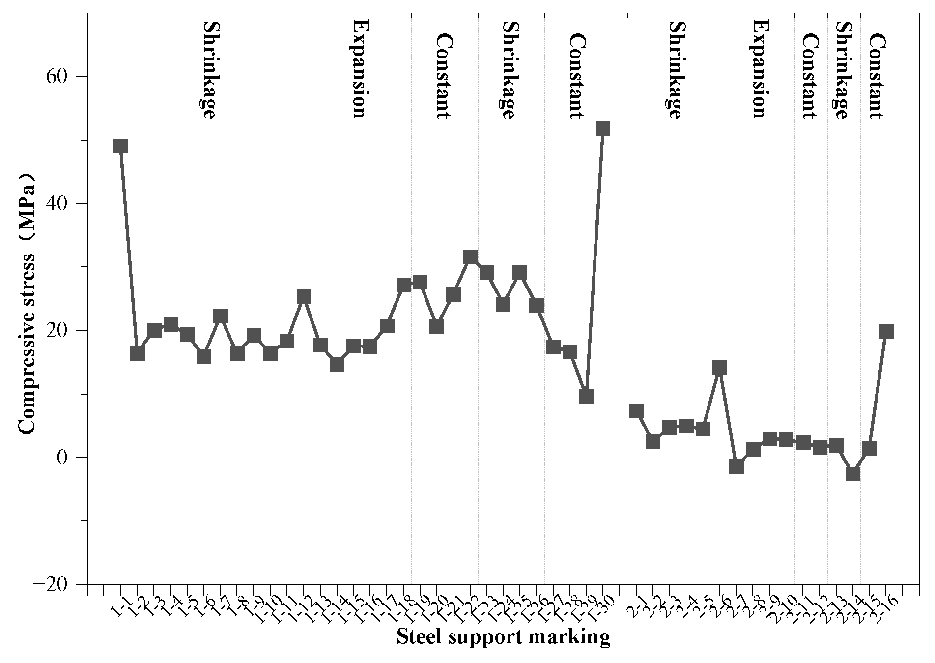
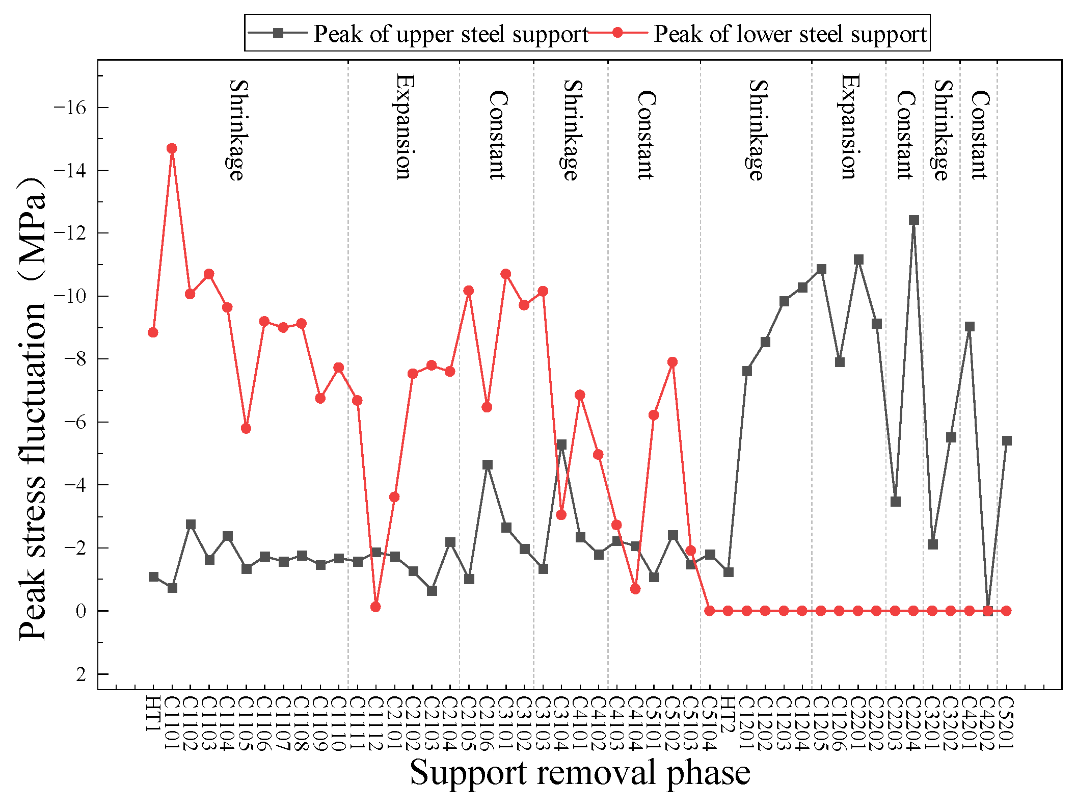
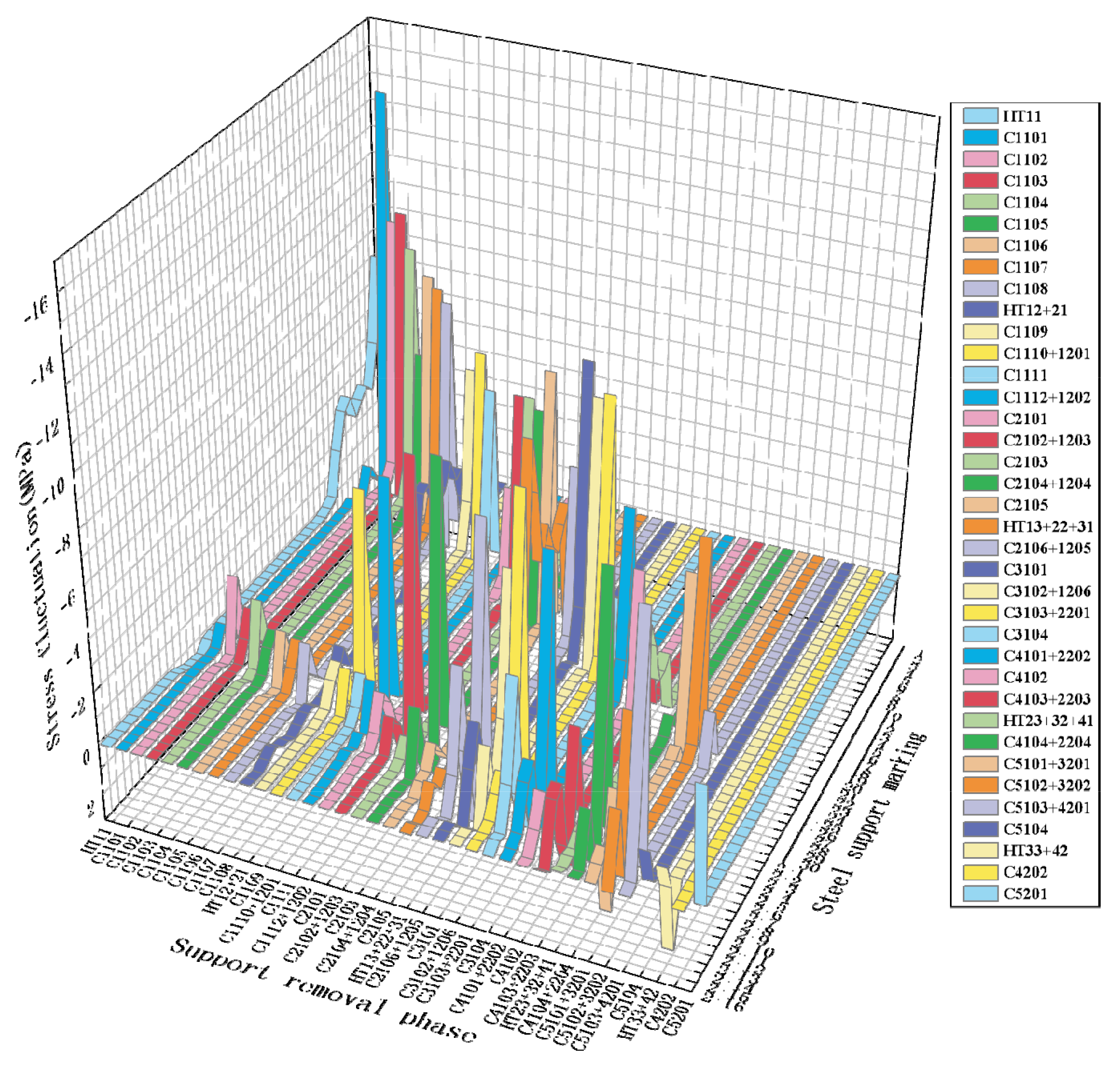
5.2. Axial Force Analysis

The stress fluctuation values in each stage of stepwise backfill and de-bracing are shown in Figure 15. The axial force fluctuation diagram demonstrates that the axial force fluctuation in each stage of the stepwise de-bracing and backfill scheme is complicated. Analysis of the design scheme indicated that the fluctuation of the axial force has the following characteristics compared with laminar de-bracing and backfilling: The influencing range is small because the solid casting and overlaying backfilling are completed in phases. In most de-bracing phases, multiple steel supports at different locations are removed. Hence, the fluctuation range and amplitude do not show any significant difference from the results obtained in the analysis of the axial force of the laminar de-bracing and backfilling.

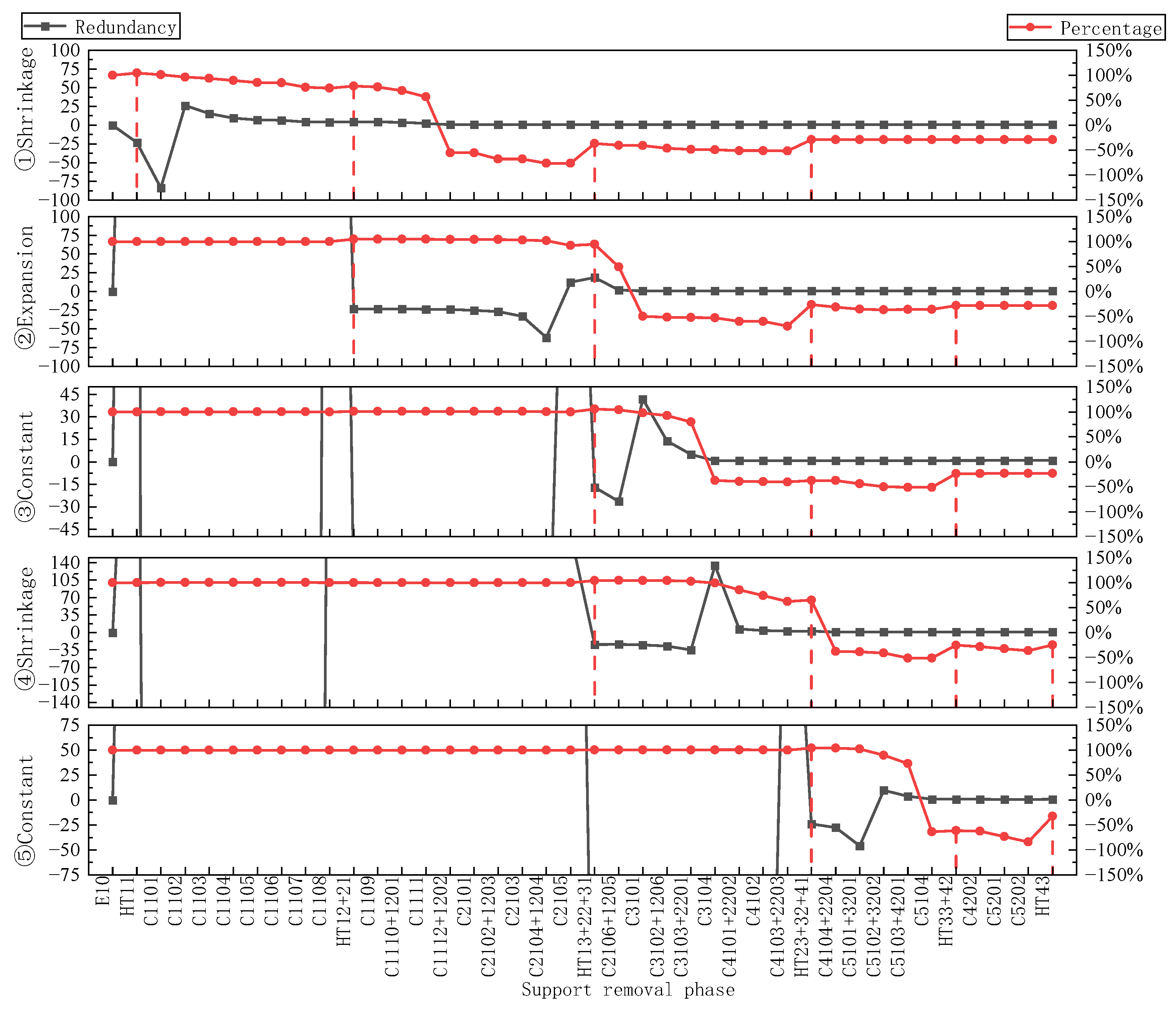
5.3. Redundancy Analysis

The redundancy values R and their corresponding relative deformations P for each variable cross-section region of stepped unbracing and backfilling at each stage of unbracing are shown in Figure 16.
A comparison of Figure 16 with the R–P diagram in the layered backfill and de-propping scheme indicates that the stepped backfill and de-propping process has the following characteristics: the total interval of de-propping is shorter; numerous sections of infinite redundancy are observed before the de-propping stage in the area of the strain cross-section (i.e., the backfill and de-propping of the previous stage have less influence on the subsequent de-propped cross-section); the redundancy drop sections caused by the removal of upper and lower steel braces are connected; and the safety reserve of the pit improves and remains stable after the corresponding de-propping stage is completed. The backfilling of the corresponding section with overburden stabilises the unsupported section while enhancing the stability of the unsupported section. Accordingly, the safety reserve of the pit is improved and remains stable after the corresponding stage of unbracing is completed. The minimum values of redundancy Rmin and relative deformation Pmin in the positive value zones of each variable cross-section area for the layered backfill and unbraced solution and the stepped backfill and unbraced solution are shown in Table 6.
In the stepped backfill and unbraced solution, the minimum values of redundancy Rmin and relative deformation Pmin in the positive region of each variable cross-section area are larger than the corresponding values in the laminar backfill and unbraced solution, with the average value increases in redundancy and relative deformation being 0.03 and 5%, respectively. In the redundancy analysis of the laminar backfill and unbraced scenario, the relative deformation of section I exhibits a large decrease when the upper steel support is removed. Meanwhile, in the stepped backfill and unbraced scenario, the minimum value of the relative deformation of section I increases by 10.52%. This phenomenon arises because the narrow section in section I and the distal end of that section in the stepped backfilling and unbracing scheme are in different stages of unbracing, resulting in the early solid casting and backfilling of the distal end of the narrow section after the removal of the upper layer of steel bracing. Accordingly, the area stabilises in advance, the successive decreases in P and R are prevented, and the influence of the unbracing of the narrow section in section I on the distal end of the narrow section is minimised.

5.4. Backfilling and De-Bracing Options

In the above analysis, the stepped backfill and dismantling scheme, while stabilising the axial force transmission path, reduces the influencing range of the dismantling stage, increases the safety reserve of the dismantling stage, strengthens the stability of the variable cross-section foundation pit during the entire dismantling process, and improves the stability of the distal end of the narrow section through phased dismantling and backfill within the narrow-section setup compared with the layered backfill and dismantling scheme. The stability of the far end of the narrow section is greatly increased by the setting scheme of the phased de-propping and backfilling. Therefore, the stepped backfill and de-bracing design is the preferred solution between the two options.

6. Conclusions

In this work, a numerical simulation of the selected section of a foundation pit, including the entire construction process, was carried out using ABAQUS. The simulation included the stable state of the support structure under actual excavation conditions, as well as the ‘gradual backfill and root by root removal’ stage in both the laminar and stepped backfilling and removal design schemes. Settlement, axial force, and redundancy analyses were carried out for the two schemes. Based on these analyses, the following conclusions were drawn:
  • Compared with the stepped backfill and split support scheme, the laminar scheme offers more convenience in observing the changing patterns of settlement values and axial forces at different stages, but it is not as good as the stepped scheme in terms of the redundancy of the support structure.
  • The redundancy R and relative deformation P effectively reflect the stability of the variable-section pit during each stage of de-bracing. In all five variable-section areas, the minimum redundancy value in the stepped scheme is greater than that in the laminated scheme, with an average increase of 0.03. In addition, the minimum relative deformation is reduced by an average of 5%, with a maximum reduction of 10.52%.
  • The stepped removal of braces stabilises the axial force transfer path and controls the range of stress fluctuations, especially during root-by-root removal of steel braces, showing higher redundancy capacity and lower deformation increments. In the lower steel support removal stage, the maximum axial force fluctuation peak value under the stepped solution is only −6.5 MPa, which is smaller than the −8.84 MPa observed in the laminar solution.
  • The stepped backfill approach effectively blocks the deformation extension effect between sections and improves the stability of the demolition support in the narrow opening and its distal structural region. In section ①, Pmin increased from −86.9% to −76.38% and Rmin increased to 0.567, which significantly reduced the deformation accumulation effect of the support system.
  • The practical significance and engineering value of this study will be further enhanced if scaling experiments on similar models are carried out for validation and analysis in subsequent work.

Author Contributions

Conceptualization, Q.H.; Methodology, Q.H. and X.Y.; Validation, J.W., Y.J. and C.Z.; Formal analysis, Q.H.; Investigation, X.Y. and X.F.; Resources, Q.H.; Data curation, Q.H.; Writing—original draft, X.Y.; Writing—review & editing, C.Z.; Supervision, C.Z.; Project administration, Y.J.; Funding acquisition, J.W. and X.F. All authors have read and agreed to the published version of the manuscript.

Funding

This research received no external funding.

Data Availability Statement

The original contributions presented in this study are included in the article. Further inquiries can be directed to the corresponding author.

Conflicts of Interest

Authors Qi Huang, Jingjiang Wu, Xiaohu Fan and Yang Jin were employed by the company Communications Construction Company of CSCEC 7th Division Co., Ltd. The remaining authors declare that the research was conducted in the absence of any commercial or financial relationships that could be construed as a potential conflict of interest.

References

  1. Shi, X.; Rong, C.; Cheng, H.; An, G.; Wu, Q.; Zheng, L. Stability Analysis of Deep Foundation Pit with a Double-Row Cast-in-Place Piles and Diagonal Steel Lattice Braces under Sloped Excavation Conditions. Sci. Rep. 2024, 14, 22761. [Google Scholar] [CrossRef] [PubMed]
  2. Li, P.; Wu, G.; Yang, J.; Liu, Q. Stability Investigation of Fully Recycled Support System of Steel-Pipe-Anchored Sheet Pile in Soft Soil Excavation. Appl. Sci. 2024, 14, 5485. [Google Scholar] [CrossRef]
  3. Zheng, G.; Lei, Y.W.; Cheng, X.S.; Li, X.Y.; Wang, R.Z. Experimental Study on Progressive Collapse Mechanism in Braced and Tied-Back Retaining Systems of Deep Excavations. Can. Geotech. J. 2021, 58, 540–564. [Google Scholar] [CrossRef]
  4. Zheng, G.; Wang, R.Z.; Cheng, X.S.; Lei, Y.W.; Li, X.Y.; Zhou, Q. Mechanism and Control of Progressive Collapse of Tied-Back Excavations Induced by Local Anchor Failure. Acta Geotech 2024, 19, 763–781. [Google Scholar] [CrossRef]
  5. Zheng, Y.; Hu, Z.; Ren, X.; Wang, R.; Zhang, E.; Long, Z. Effects of Partial Supporting Pile Removal from Deep Foundation Pits by Shallow Excavation Method in Loess Areas. Adv. Mater. Sci. Eng. 2021, 2021, 9934113. [Google Scholar] [CrossRef]
  6. Xie, Z.; Liu, X.; Niu, X.; Jian, J.; Xu, C.; Liao, J. Study on the Influence of the Performance Weakening of the Disconnectable Coupling (DC) Joint of Steel Support on the Retaining Structure of a Foundation Pit. Buildings 2024, 14, 1330. [Google Scholar] [CrossRef]
  7. Jin, Y.; Zhao, H.; Zheng, C.; Liu, J.; Ding, C. Effect of Steel Support Cross-Section and Preloaded Axial Force on the Stability of Deep Foundation Pits. Buildings 2024, 14, 2532. [Google Scholar] [CrossRef]
  8. Lu, T.S.; Liu, S.Y.; Cai, G.J.; Wu, K.; Xia, W.J. Study on the Disturbance and Recompression Settlement of Soft Soil Induced by Foundation Pit Excavation. Rock Soil Mech. 2021, 42, 565–573. [Google Scholar] [CrossRef]
  9. Xing, T.; Jing, Y.; Ye-xiang, J.; Xing-wang, L.; Ying, L. Calculation of Layered Unloading Additional Stress of Foundation Pit Based on Mindlin Solution and the Analysis of Multiple Factors Influencing the Rebound Deformation. Rock Soil Mech. 2020, 41, 2432–2440. [Google Scholar] [CrossRef]
  10. Song, D.; Chen, Z.; Dong, L.; Tang, G.; Zhang, K.; Wang, H. Monitoring Analysis of Influence of Extra-Large Complex Deep Foundation Pit on Adjacent Environment: A Case Study of Zhengzhou City, China. Geomat. Nat. Hazards Risk 2020, 11, 2036–2057. [Google Scholar] [CrossRef]
  11. Lin, P.; Liu, P.; Ankit, G.; Singh, Y.J. Deformation Monitoring Analysis and Numerical Simulation in a Deep Foundation Pit. Soil Mech. Found. Eng. 2021, 58, 56–62. [Google Scholar] [CrossRef]
  12. Qiu, H.; Zhou, Y.; Ayasrah, M. Impact Study of Deep Foundations Construction of Inclined and Straight Combined Support Piles on Adjacent Pile Foundations. Appl. Sci. 2023, 13, 1810. [Google Scholar] [CrossRef]
  13. Wang, M.; Zhao, D.; Wang, W.; Ma, P.; Jiang, S. Deformation Law and Spatial Effect of Deep Foundation Pits for Subway Construction in Soil-Rock Composite Strata in Seasonally Frozen Areas. Teh. Vjesn.-Tech. Gaz. 2023, 30, 1315–1325. [Google Scholar] [CrossRef]
  14. Wu, Y.; Zhou, X. Construction Pit Deformation Measurement Technology Based on Neural Network Algorithm. J. Intell. Syst. 2023, 32, 20220292. [Google Scholar] [CrossRef]
  15. Zhu, Y.; Qin, H.; Zhang, X.; Wei, D.; Zhai, L.; Hu, L. Innovative Three-Row Pile Support System of Ultra-Deep Foundation Pit and Cooperative Construction Technology with Basement for High-Rise Tower Structures. Buildings 2024, 14, 1003. [Google Scholar] [CrossRef]
  16. Liu, J.Y.; Li, B.; Liu, Y.; Cai, S.B. Design Method of Redundancy of Brace-Anchor Sharing Supporting Based on Cooperative Deformation. IOP Conf. Ser. Earth Environ. Sci. 2017, 94, 012202. [Google Scholar] [CrossRef]
  17. Shadabfar, M.; Mahsuli, M.; Zhang, Y.; Xue, Y.D.; Ayyub, B.M.; Huang, H.W.; Medina, R.A. Resilience-Based Design of Infrastructure: Review of Models, Methodologies, and Computational Tools. ASCE-ASME J. Risk Uncertain. Eng. Syst. Part A-Civ. Eng. 2022, 8, 03121004. [Google Scholar] [CrossRef]
  18. Yi, F.; Su, J.; Zheng, G.; Cheng, X.S.; Zhang, J.T.; Lei, Y.W. Overturning Progressive Collapse Mechanism and Control Methods of Excavations Retained by Cantilever Piles. Eng. Fail. Anal. 2022, 140, 106591. [Google Scholar] [CrossRef]
  19. Sarmiento, S.; Thons, S.; Gonzalez-Libreros, J.; Bjornsson, I.; Sas, G. Comparison and Joint Evaluation of Importance, Redundancy and Robustness Indicators Applied to Aging Prestressed Concrete Bridges. Nord. Concr. Res. 2024, 70, 147–171. [Google Scholar] [CrossRef]
  20. Li, S.; Wang, F.; Le, Y.; Que, Q.; Su, Y.; Lin, H. Design and Deformation Pattern Simulation of Deep Excavation Support Structures. Front. Earth Sci. 2024, 12, 1416957. [Google Scholar] [CrossRef]
  21. Kim, J.; Yi, S.; Park, J.; Kim, T. Efficient System Reliability-Based Disaster Resilience Analysis of Structures Using Importance Sampling. J. Eng. Mech. 2024, 150, 4024081. [Google Scholar] [CrossRef]
  22. Wu, J.; Ye, S.H.; Wang, Z.Q.; Yang, D. Application and Automatic Monitoring and Analysis of Hybrid Support Structure in Ultra-DEEP Foundation Pit Engineering in the Lanzhou Area under Complex Environmental Conditions. Water 2023, 15, 1335. [Google Scholar] [CrossRef]
  23. Sun, Z.; Wang, C.; Wu, J. Industry Foundation Class-Based Building Information Modeling Lightweight Visualization Method for Steel Structures. Appl. Sci. 2024, 14, 5507. [Google Scholar] [CrossRef]
  24. Ke, C.; Fan, Y.; Jiang, J. Influence of Staggered Truss on Progressive Collapse-Resistant Behavior of Steel Frame Structures. Buildings 2024, 14, 931. [Google Scholar] [CrossRef]
  25. Chen, Q.; Wang, H.; Bhattacharya, B.; El-Tawil, S.; Agrawal, A.K.; Wong, W. Reliability-Based Framework for Structural Robustness Evaluation of Bridges. J. Bridge Eng. 2024, 29, 4024035. [Google Scholar] [CrossRef]
  26. Chen, Y.; Liao, Y.; Zhu, L.; Chen, L.; Chen, Y. Robustness of a Steel Truss Bridge Subjected to Sudden Member Breakage during the Continuous-to-Simply-Supported Transition. Buildings 2024, 14, 3035. [Google Scholar] [CrossRef]
  27. You, X.; Zhou, Q.; Xiao, Y.; Tong, L.; Yang, Q. Numerical Study on the Coupling Effect on a Retaining Structure of a Complex Deep Foundation Pit Group Excavation in a Soft-Soil Area. Appl. Sci. 2023, 13, 3263. [Google Scholar] [CrossRef]
  28. Di, H.G.; Guo, H.J.; Zhou, S.H.; Chen, J.M.; Wen, L. Investigation of the Axial Force Compensation and Deformation Control Effect of Servo Steel Struts in a Deep Foundation Pit Excavation in Soft Clay. Adv. Civ. Eng. 2019, 2019, 5476354. [Google Scholar] [CrossRef]
  29. Wang, Z.; Wang, C. Analysis of Deep Foundation Pit Construction Monitoring in a Metro Station in Jinan City. Geotech. Geol. Eng. 2019, 37, 813–822. [Google Scholar] [CrossRef]
  30. Lu, B.; Zhao, W.; Du, X.; Li, S.; Guan, Y.; Wang, Z. Analysis of Ultimate Bearing Capacity and Parameters of Steel Support Cutting Pipe Roofing Structure. Transp. Res. Rec. 2022, 2676, 348–366. [Google Scholar] [CrossRef]
  31. Cheng, X.; He, J.; Li, X.; Xia, Q.; Su, H.; Chen, C. Deformation rule of bored pile & steel support for deep foundation pit in sandy pebble geology. Stavební Obz.-Civ. Eng. J. 2023, 33, 282–297. [Google Scholar] [CrossRef]
  32. Wang, X.; Song, Q.; Gong, H. Research on Deformation Law of Deep Foundation Pit of Station in Core Region of Saturated Soft Loess Based on Monitoring. Adv. Civ. Eng. 2022, 2022, 7848152. [Google Scholar] [CrossRef]
Figure 1. Geometric model construction of each component.
Buildings 15 01903 g001
Figure 2. Monitoring point number location.
Buildings 15 01903 g002
Figure 3. Comparison of finite element calculation results and monitoring data.
Buildings 15 01903 g003
Figure 4. Steel support number setting.
Buildings 15 01903 g004
Figure 5. Design scheme for the removal of steel support and layered backfill.
Buildings 15 01903 g005
Figure 6. Design scheme for the removal of steel support and stepped backfill.
Buildings 15 01903 g006
Figure 7. Settlement analysis path.
Buildings 15 01903 g007
Figure 8. Surface settlement values along the analysed path.
Buildings 15 01903 g008
Figure 9. Axial force values of steel supports in the support structure steady state (E10).
Buildings 15 01903 g009
Figure 10. Layered backfill and stress fluctuations in split bracing.
Buildings 15 01903 g010
Figure 11. Plot of peak stress fluctuations.
Buildings 15 01903 g011
Figure 12. Laminated backfill and demolition support R–P drawing.
Buildings 15 01903 g012
Figure 13. Deformation cloud diagrams of concrete support structure.
Buildings 15 01903 g013
Figure 14. Surface settlement values along the analysed paths.
Buildings 15 01903 g014
Figure 15. Fluctuating values of stress for stepped backfill and removal of braces.
Buildings 15 01903 g015
Figure 16. Stepped backfill and demolition support R–P chart.
Buildings 15 01903 g016
Table 1. Soil parameters for variable-section footings.
Soil Layer NameDensity
(kg/m3)
Angle of Internal
Friction (°)
Cohesion
(kPa)
Poisson’s RatioElastic Modulus (MPa)
silty clay200020330.221.5
shale250025500.26000
conglomerates214028400.215,500
Table 2. Material parameters of variable-section pit support structure.
MakingsDensity (kg/m3)Modulus of Elasticity (MPa) Poisson’s Ratio
C15 concrete224022,0000.2
C20 concrete236025,5000.2
C30 concrete245030,0000.25
Q235B steel7850200,0000.3
Table 3. Stability calculation and analysis step settings for the supporting structure.
No.Content of the Analysis StepNo.Content of the Analysis Step
1Ground stress equilibrium11Step 5 Excavation
2Enclosure construction12Erection of second and first steel supports for Step 5
3Step 1 Excavation13Step 6 Excavation
4Erection of first steel support for Step 114Erection of second and first steel supports for Step 6
5Step 2 Excavation15Step 7 Excavation
6Erection of first steel support for Step 216Erection of second and first steel supports for Step 7
7Step 3 Excavation17Step 8 Excavation
8Erection of second and first steel supports for Step 318Step 9 Excavation
9Step 4 Excavation19 *Step 10 Excavation
10Erection of second and first steel supports for Step 4
* Analysis Step 19 (E10) is the stable state of the support structure.
Table 4. Setup of layered unbracing analysis steps.
No.Analysis StepNo.Analysis StepNo.Analysis StepNo.Analysis StepNo.Analysis StepNo.Analysis StepNo.Analysis Step
20HT127C110734C210241C310348C510255C120462C3201
21C110128C110835C210342C310449C510356C120563C3202
22C110229C110936C210443C410150C510457C120664C4201
23C110330C111037C210544C410251HT258C220165C4202
24C110431C111138C210645C410352C120159C220266C5201
25C110532C111239C310146C410453C120260C220367C5202
26C110633C210140C310247C510154C120361C220468HT3
Table 5. Step-by-step analysis setup for the removal of braces.
No.Analysis StepNo.Analysis StepNo.Analysis StepNo.Analysis StepNo.Analysis StepNo.Analysis Step
20HT1127C110734C210141C310148HT23+32+4155C4202
21C110128C110835C2102+120342C3102+120649C4104+220456C5201
22C110229HT12+2136C210343C3103+220150C5101+320157C5202
23C110330C110937C2104+120444C310451C5102+320258HT43
24C110431C1110+120138C210545C4101+220252C5103+4201--
25C110532C111139HT13+22+3146C410253C5104--
26C110633C1112+120240C2106+120547C4103+220354HT33+42--
Table 6. Summary of minimum values of redundancy and minimum values of relative deformations in positive value areas.
Variable Cross-Section AreaScheme for Removal of Steel Support and Layered BackfillScheme for Removal of Steel Support and Stepped Backfill
RminPminRminPmin
I Constant section 0.537−86.9%0.567−76.38%
II Expansion section 0.573−74.59%0.588−69.96%
III Constant section 0.649−54.18%0.662−51.14%
IV Contraction section 0.630−58.75%0.660−51.44%
V Constant section0.525−90.50%0.544−83.98%
Disclaimer/Publisher’s Note: The statements, opinions and data contained in all publications are solely those of the individual author(s) and contributor(s) and not of MDPI and/or the editor(s). MDPI and/or the editor(s) disclaim responsibility for any injury to people or property resulting from any ideas, methods, instructions or products referred to in the content.

