Article

Segmented Timber Shells for Circular Construction: Relocation, Structural Assessment, and Robotic Fabrication of a Modular, Lightweight Timber Structure

1
Institute of Building Structures and Structural Design (ITKE), University of Stuttgart, Keplerstrasse 11, 70174 Stuttgart, Germany
2
Department Timber Constructions, Materials Testing Institute (MPA), University of Stuttgart, Pfaffenwaldring 4B, 70569 Stuttgart, Germany
3
Institute of Engineering Geodesy (IIGS), University of Stuttgart, Geschwister-Scholl-Str. 24D, 70174 Stuttgart, Germany
4
Institute for Computational Design and Construction (ICD), University of Stuttgart, Keplerstrasse 11, 70174 Stuttgart, Germany
*
Author to whom correspondence should be addressed.
Buildings 2025, 15(11), 1857; https://doi.org/10.3390/buildings15111857
Submission received: 30 April 2025 / Revised: 8 May 2025 / Accepted: 23 May 2025 / Published: 28 May 2025
(This article belongs to the Section Building Structures)

Abstract

:
Segmented timber shells present a novel building system that utilizes modular, planar building components to create lightweight free-form structures in architecture. Recent advancements in the research field of segmented timber shells pursue, among others, two fundamentally opposing research objectives. 1. The modularity of their building components facilitates the reuse of such structures in response to a changing built environment. 2. Advanced developments aim at establishing segmented timber shells as permanent building structures for sustainable architecture. This paper addresses the first research objective through the successful relocation of the BUGA Wood Pavilion in the context of the proposed methodology of Co-Design for circular construction. The methods and results involve integrative design and engineering processes and advanced quality assessment methods, including structural, geodetic, and physical properties for modular timber constructions. The BUGA Wood Pavilion serves as a building demonstrator for the presented research on segmented shells as lightweight, reusable, and durable timber structures.

1. Introduction

The construction sector is one of the fastest-growing industries today [1]. This growth stems from an increasing demand for new buildings and infrastructure to meet the ecological, economic, social, and cultural needs of people worldwide [2,3,4]. However, such progress entails extensive consumption of global resources. The world’s building and construction sector is responsible for the depletion of more than 50% of raw materials and 40% of energy consumption [5,6,7], thus contributing significantly to the environmental deterioration caused by pollution and degradation of natural eco-systems [8]. In light of the imminent effects of the construction sector on climate change and the consequent rising global concern about its impact on the environment [9], a rethink of design and construction is imperative [10]. In principle, construction projects can be steered towards sustainability on two interdependent and reciprocal levels: a. the project content, such as the design, construction materials, or implemented technologies; and b. project processes, such as production processes, project management, etc. [11,12]. Both developments pursue the objective of a more restorative and regenerative construction sector, transcending from a predominantly linear economy to a circular economy [13], which uses resources efficiently, for the longest possible lifetime, and over multiple life cycles [14,15,16,17,18].

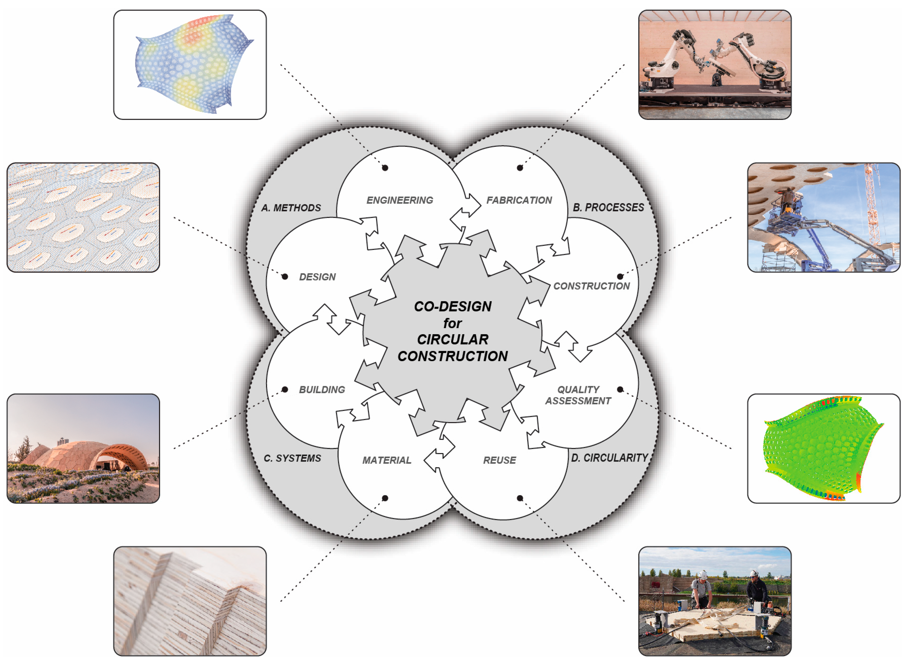
1.1. Co-Design for Circular Construction

Today, building construction is a predominantly linear process defined by a unidirectional chain of consecutive phases from design to construction through to maintenance and finally end-of-life. This linearity equally extends to the digital technologies used in the design and construction of buildings. Innovations to stimulate integrative design and enhance productivity in construction remain incremental and fragmented [19,20,21]. However, various holistic sustainability concepts exist, aiming to integrate the principles of circular economy into their design and planning process. This includes, among others, cradle-to-cradle [22], regenerative design [23], and circular construction [1,24], which entails the reduction of material consumption, waste production, and emissions through the reuse and recycling of both construction materials and building components to secure resources throughout a prolonged life cycle. A few implement design principles for the disassembly (design for disassembly) [25,26,27,28], adaptation (design for adaptability) [25,27], reuse (design for reuse) [25,29], and up- or recycling (design for recycling) [30] of a building. To this day, however, the building sector continues to face obstacles that prevent the comprehensive inclusion of these methodologies [18,31,32], as most buildings are unique constructions composed of a multitude of different components and materials that require interaction on a large scale to achieve diverse performances [33,34].
Co-Design describes a rather novel approach that merges the reciprocal interrelations of processes, methods, and systems into one integrative design and construction methodology, which efficiently harnesses the full potential of digitalization [35,36,37]. In the context of circular construction, Co-Design offers the potential for innovative and functional solutions through inclusive and collaborative decision-making, balancing technical performance with environmental and social concerns in accordance with the design criteria established at the outset of a project. The authors propose an extension to the fundamental principles of Co-Design by integrating design principles and advanced quality assessment models for reusable building systems toward circular construction. In this context, the BUGA Wood Pavilion, a lightweight segmented timber shell structure [38,39], serves as an excellent case study for the investigation and evaluation of the proposed design methodology, henceforth referred to as Co-Design for circular construction (illustrated in Figure 1).

1.2. Segmented Timber Shells

Segmented timber shells (STSs) are modular constructions composed of lightweight building components made of renewable wooden materials. The planarity of their components facilitates economic manufacturing within standardized workshop environments, yielding building products of high quality and integration. In addition, the substantial design freedom in the shape and dimension of these components enables the efficient nesting of their individual building parts, reducing production waste to the minimum possible. The modularity and lightness of STSs allow for their effective on-site assembly and disassembly at a low level of disruption and pollution for the surrounding environment. By integrating adequate design and engineering strategies, STSs provide great potential for adaptation or extension in the context of an evolving urban architecture. In terms of their application in circular construction, these qualities render them ideal for demountable and reusable structures, as shown here. As curved modular structures, however, segmented timber shells represent an intricate building system.
Characteristic of thin shell structures, their shape is often derived using form-finding methods [40], aiming to transfer external loads primarily through compressive forces to achieve an almost pure membrane stress state. Such slender shells in compression are known to respond very sensitively to changes in their global geometry, resulting in larger deflections and reducing their load-bearing capacity. Therefore, it is imperative to avoid geometrical deviations from their optimized shape, as such imperfections can increase the probability of instabilities such as “buckling phenomena or sudden failures due to excessive bending” [41]. Furthermore, the nature of segmented shells as subdivided planar continuum shells poses a significant challenge to their design, engineering, fabrication, and construction. The large number of joints between individual shell segments creates a disruption of material continuity, which naturally weakens the structural rigidity of shells by altering the flow of force. Moreover, these structural specifics necessitate high-precision manufacturing of the shell components to ensure their constructability, allowing a significant proportion of the internal shell forces to be transferred via material contact. These stringent requirements for the accuracy of STSs are of crucial importance, as changes to the geometric, structural, or physical state of their building components may result in unanticipated planning and execution errors. Therefore, the implementation of advanced quality assessment models helps to address the inherent complexity of STSs, contributing to a holistic decision-making process that considers their reusability and longevity throughout multiple life cycles [42].

1.3. Advanced Quality Assessment Models

Quality in construction has gained increasing importance in recent decades [43,44,45,46]. For conventional building processes, certain quality assessment procedures have thus developed that can be used to determine the quality of a building. With the development of new manufacturing and construction technologies, current building strategies raise the question of the progressive quality of new buildings and how this quality can be measured. In accordance with DIN EN ISO 9000 [47], the term quality is defined as “the degree to which a set of inherent characteristics fulfills requirements”. The definition of these characteristics, which are significantly responsible for the quality, can be considered from different perspectives. The term quality is often associated with technical characteristics such as correctness or completeness; however, social and environmental quality characteristics also play an important role [42]. To be able to carry out a quality assessment, the requirements must be defined first. Here, both the quality characteristics and the quality parameters, which represent the measurable variables, are defined. In addition, the necessary criteria, target values, or conditions are defined. Consequently, the quality assessment takes place at defined control and decision points [42]. A control point is a point at which the quality of the product or process is checked, while at a decision point, the existing quality is decisive for further procedures. In this contribution, the focus is on geometric and structural quality as a part of technical quality and on the assessment of control points.

1.4. Research Development

This contribution describes the integrative design process and quality assessment methods involved in the successful relocation of the BUGA Wood Pavilion from its initial erection site in Heilbronn in 2019 to a new location in Mannheim in 2023. The authors aim to provide insights into the design and engineering strategies, planning efforts, and constructive solutions that were developed and applied for the reuse of the timber shell structure. In addition, our multidisciplinary group of researchers places particular emphasis on the interrelationships and interdependencies embodied in the methodology of Co-Design for circular construction through a holistic quality assessment to investigate the long-term behavior of reusable timber constructions. This includes investigations of global and local changes in the geometric, structural, and physical properties of the segmented timber shell. The research presented in this paper contributes to ongoing developments regarding STSs towards reusable and resource-efficient timber structures.

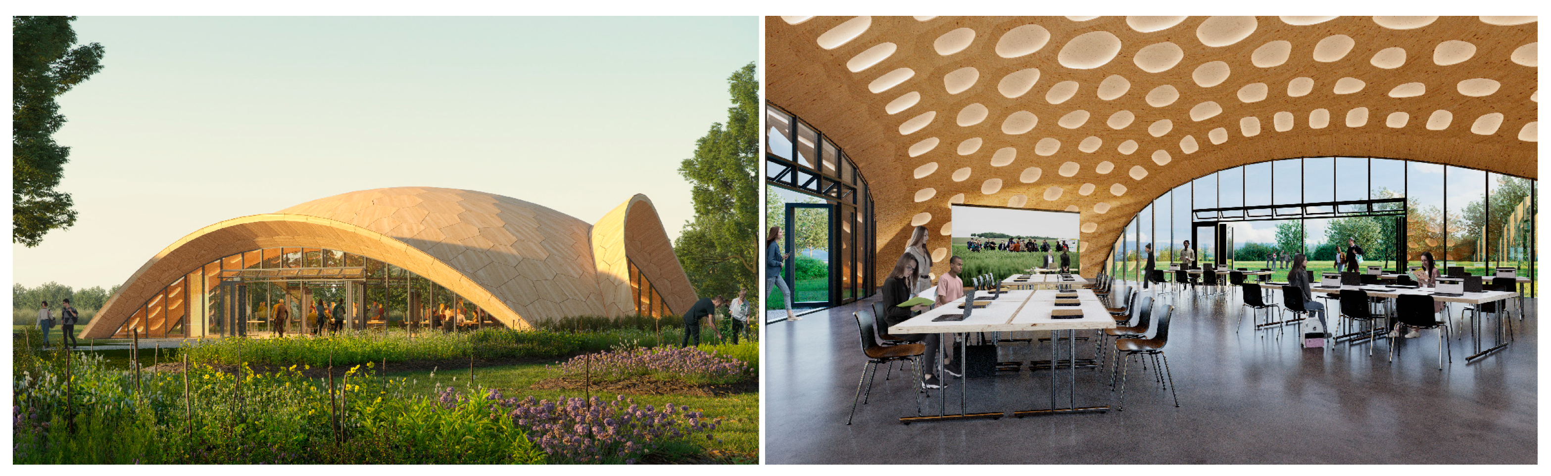
2. BUGA Wood Pavilion 2023

The BUGA Wood Pavilion is a long-span segmented timber shell initially planned for the Federal Horticultural Show in 2019 (in German: Bundesgartenschau or BUGA) in Heilbronn, Germany. After a service life of four years, the pavilion was relocated to the subsequent BUGA 2023 in Mannheim, Germany (see Figure 2). Developed in an interdisciplinary research venture at the University of Stuttgart [48,49,50,51,52,53,54], the segmented timber shell utilizes the integrative approach of Co-Design by incorporating computational design, engineering, and robotic fabrication technologies [36] to assess the potentials of STSs toward resource-efficient and reusable structures [55]. Today, the BUGA Wood Pavilion is part of the family of innovative building demonstrators developed within the Cluster of Excellence “Integrative Computational Design and Construction for Architecture” (IntCDC) at the University of Stuttgart.

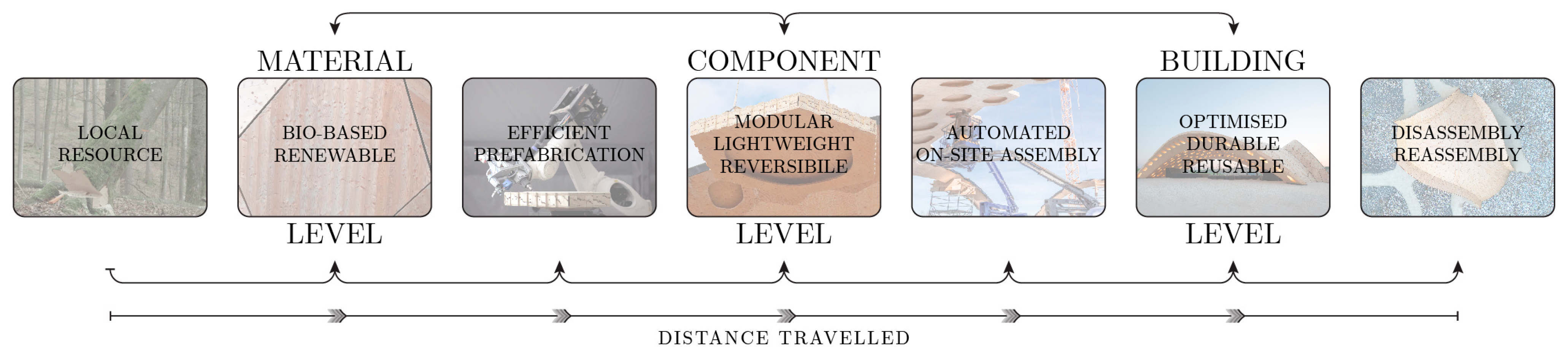
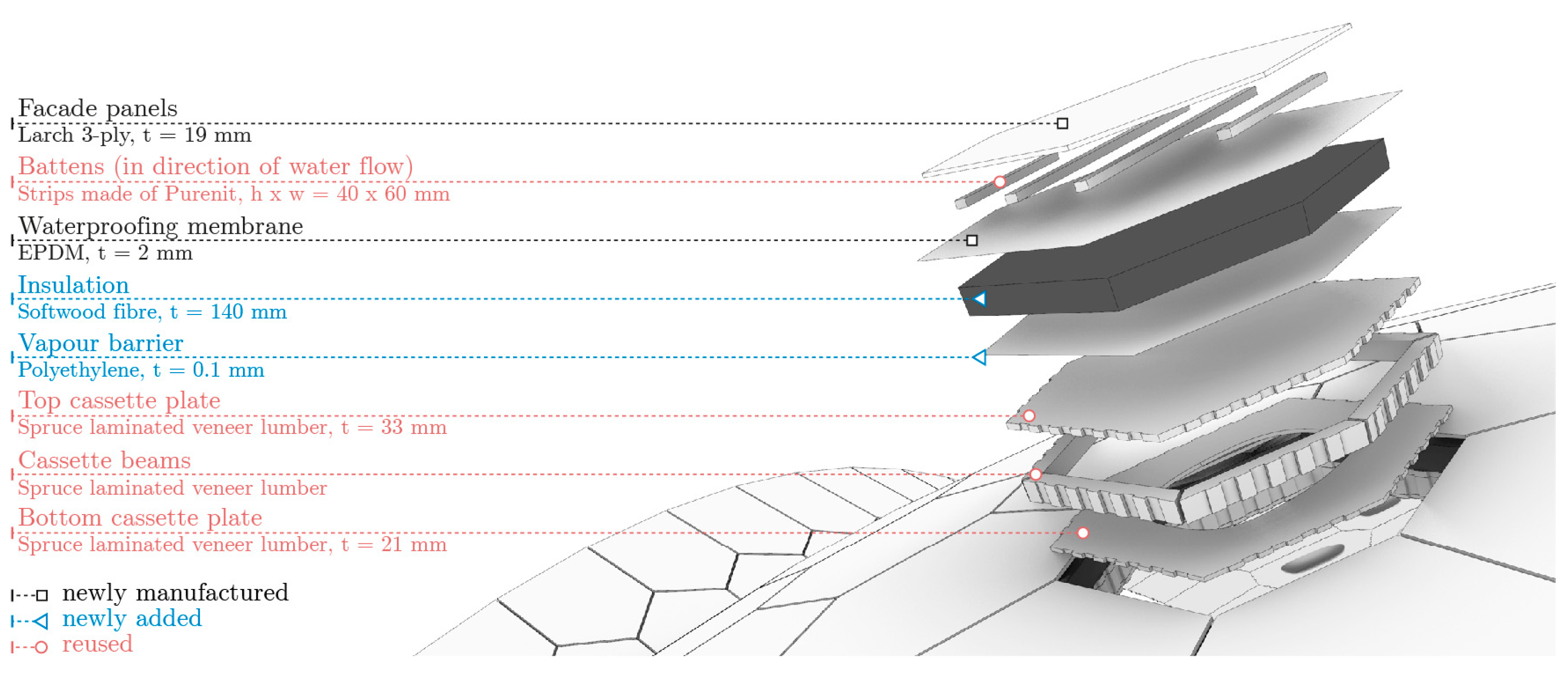
2.1. Design for Reuse

The reusability of STSs requires the successful integration of circular construction principles in the initial conception, design, and construction of their building system. The research described in this article applies such integration for the BUGA Wood Pavilion on three levels of hierarchy.
On a material level, a sensible selection of the employed building materials is of crucial importance. Renewable materials of low energy production and low environmental impact represent a core requisite for sustainable construction [11,12,56]. In the case of the BUGA Wood Pavilion, engineered timber, i.e., laminated veneer lumber (LVL), proved to be the optimal choice due to its high structural performance, dimensional properties, strength, and rigidity. On a component level, the building system design must allow for its efficient manufacturing, construction, and deconstruction, including strategies for reuse and recycling. In this context, the building components must be transportable and feature a reversible connection design using reusable connectors [57]. In addition, the building system must accommodate a high degree of functional integration paired with a modular composition of all building layers, enabling their clean separation after use [24]. On a building level, sustainable design should minimize material consumption through shape or topology optimization of the structure or its components. Moreover, building designs should seek to maximize their lifespan, enabling adaptive strategies for future reuse or expansion at low cost and without additional excessive planning efforts. Figure 3 illustrates the integration of the principles of circular construction for segmented timber shells.
The BUGA Wood Pavilion represents a key research demonstrator emerging from the fundamental idea of STSs as modular, resource-efficient, and reusable building systems. The development of the segmented timber shell involved integrative computational design methodologies to synchronise architectural form, segmentation strategies, structural behavior, and digital fabrication through iterative, feedback-driven processes. Emphasis was placed on establishing parametric models that enable this synthesis by addressing the complex interdependencies inherent to STSs, particularly those arising from their interdisciplinary nature, which combines architecture, structural engineering, and construction. These models supported the generation of double-layered structural models for the simulation of hollow cassette components, incorporating multi-layered material properties and sophisticated spring models to simulate joint stiffness in multiple directions, allowing for highly precise and detailed digital representations that are closely aligned with the built shell structure [38,39].
Conceptualized, designed, planned, and manufactured within a radius of less than 70 km, it utilizes the strengths of computational design and the digital prefabrication of the regional timber industry of Baden-Württemberg, Germany. In addition, it emphasizes the geographical proximity of the individual stations of the pavilion’s evolution, translating into low embodied greenhouse gas emissions linked to transportation, reduced costs, and enhanced collaboration among the various project stakeholders.
In preceding studies [48,49], the cassette system of the BUGA Wood Pavilion was evaluated through life cycle assessment (LCA) and life cycle costing (LCC) analyses and compared against a solid CLT system and a reference case study featuring a 55 mm thick monolithic high-performance concrete shell. Quantitative comparisons showed that the cassette system achieves equivalent deformation performance, with 41% less weight and a 30% lower environmental impact than the CLT system, primarily due to its material efficiency. Although the cassette system requires approximately 45% more fabrication time, its optimized material use results in a 25% reduction in production costs. Compared to the concrete shell, which had a structural weight of 140 kg/m2, the CLT system reached 60 kg/m2 and the cassette system just 35 kg/m2, illustrating the substantial lightweight advantage of the latter. Despite the concrete system exhibiting competitive production costs, its environmental impact was significantly higher across the assessed life cycle phases. These findings affirm that although the cassette system necessitates a more complex robotic fabrication process, it offers superior ecological and structural performance, validating its long-term viability in lightweight and sustainable timber construction.

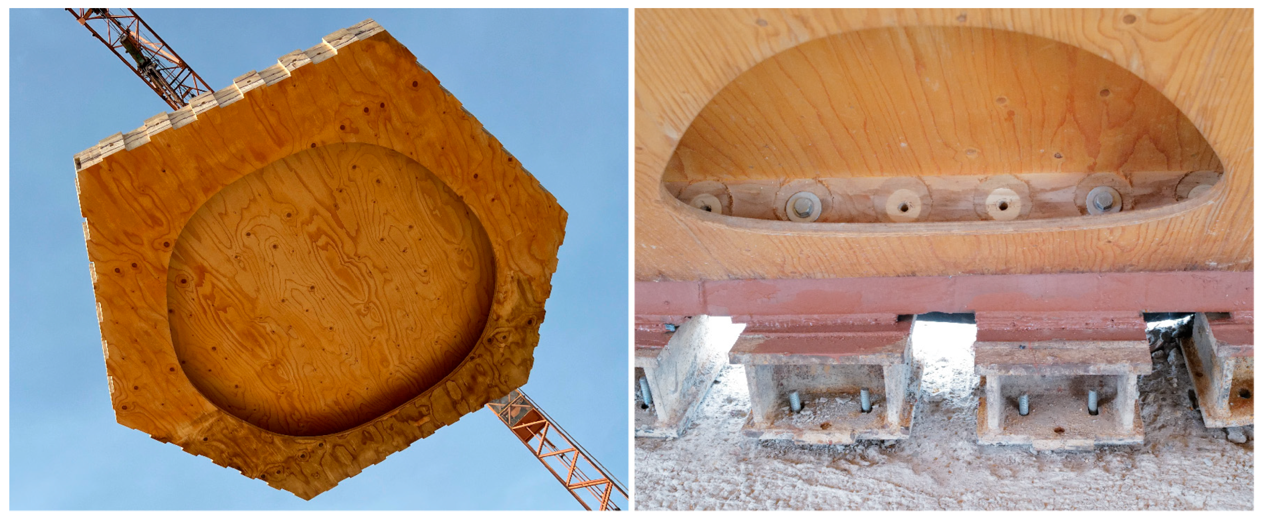
2.2. Relocation of the Shell Structure

The original concept for the BUGA Wood Pavilion 2019 envisaged an exhibition period of six months until the end of the Federal Horticultural Show in October 2019. Delays in construction works to redevelop the grounds, however, caused the timber shell to remain on site for another three years before its dismantling commenced at the end of 2022.

2.2.1. Non-Destructive Dismantling

Non-destructive disassembly of the building components was of the highest priority in the dismantling process of the timber shell. This was made possible primarily through the modular construction system of the BUGA Wood Pavilion, which consists of hollow cassette components and a reversible bolt-and-finger joint connection strategy applied to all edge connections of the shell, except along the arches. In these areas, a non-reversible screw-and-finger joint connection was used, necessitating the disassembly of each arch into two assembly groups without removing the screw connections (see Figure 4).
The timber construction company removed the façade layer, comprising three-ply solid wood panels made of larch, and the battens. The waterproofing membrane remained on the structure throughout the entire dismantling process, ensuring proper protection of the shell from rainwater, and was removed locally during the disassembly of individual cassettes (see Figure 5). The shell’s load-bearing structure was dismantled in reverse order to its 2019 construction (see [38]). Instead of dismantling the cassettes along the wings first, disassembly commenced with the components at the apex of the shell to relieve the body components, which were more critical in terms of removability. Additional measures to unload the shell structure were shoring scaffoldings supporting each of the three arches at their center of span, respectively, and simple timber struts serving as point supports.
A hydraulic system, comprising four high-pressure cylinders providing a parallel pressure distribution of 5–10 bar (depending on the component size and friction resistance), one hand pump, and four Z-shaped steel profiles, assisted the craftsmen in the removal of each shell component normal to its respective inclined shell position, as shown in Figure 6.
Once a cassette was detached from its adjacent components, a tower crane moved it to a temporary storage area located next to the shell (see Figure 5), where the components were loaded onto a lorry in packages of five for onward transport to Mannheim. The average time required to lift one cassette was approximately 15 min. The preparatory measures, including setting up the hydraulic system, consumed approximately another 15 min. The total dismantling time for the BUGA Wood Pavilion took 30 days, including all façade layers, connectors, and timber cassettes. The 30 steel box profiles connecting the timber shell to the concrete foundation were also dismantled to be reused and reconstructed in the pavilion in Mannheim.

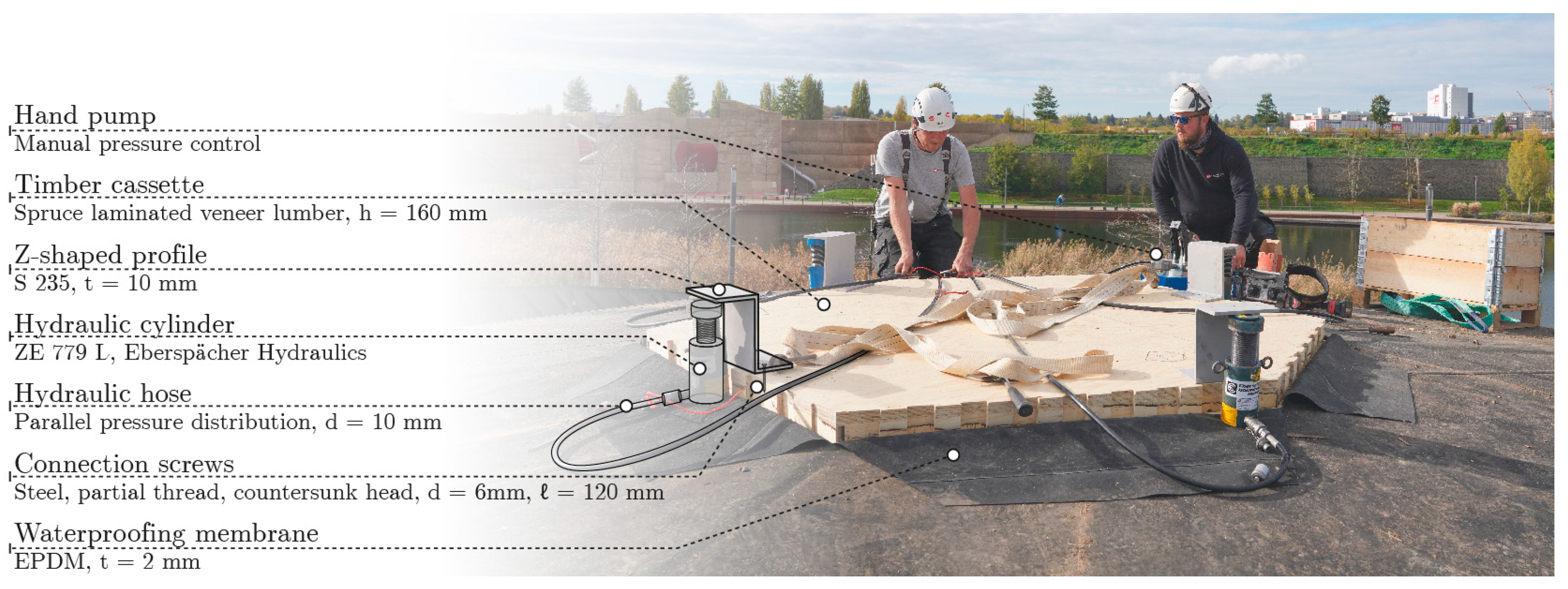
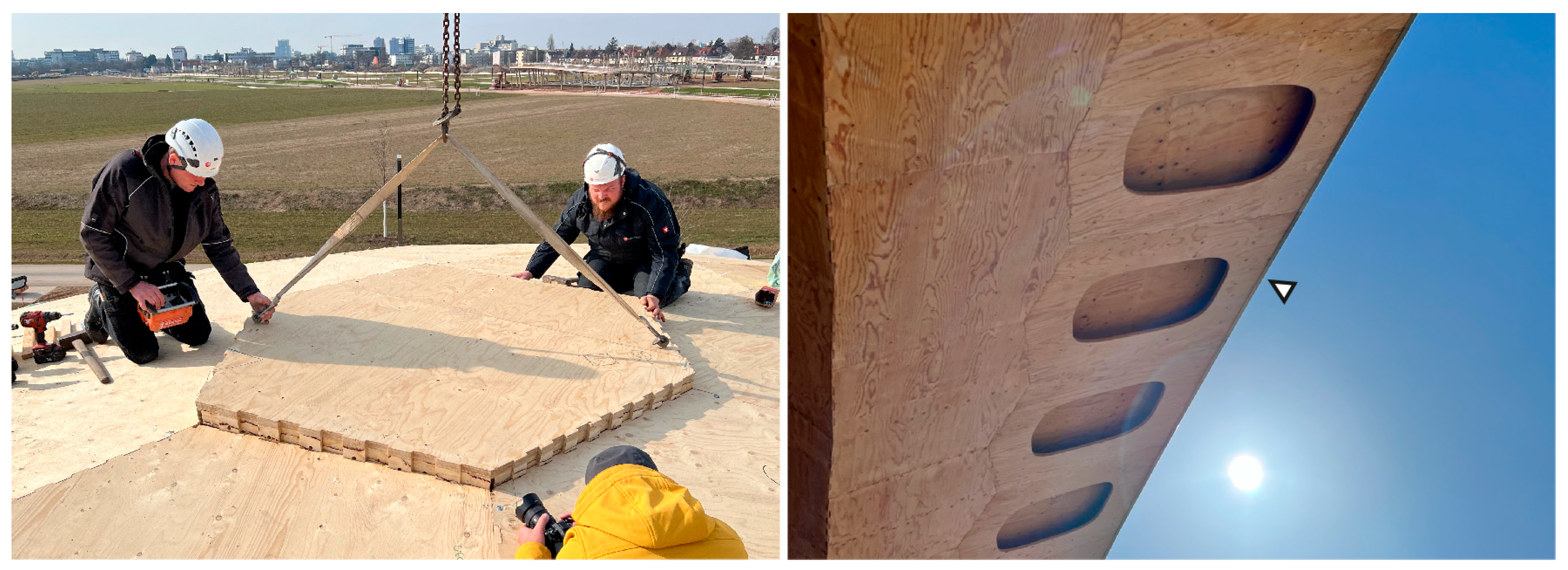
2.2.2. Reconstruction

The dismantling of the BUGA Wood Pavilion was completed in early December 2022. In late January of 2023, the reconstruction of the timber shell in Mannheim began. The same team of three craftsmen completed the load-bearing structure of the timber shell in only twelve working days (see Figure 7, left), reusing all of the 376 timber cassettes, all 107 steel parts (30 box profiles and 77 steel components), and approximately 90% of the 4262 fitting bolts.
Both waterproofing membrane and battens were reused for the façade layer; however, the façade panels were replaced with new ones to restore the mint appearance of the pavilion (see Figure 2, right). Along the wings of the shell, an additional metal sheet provided enhanced constructional wood protection. This measure was required as a minor deficiency in the original design was identified in this area, as shown in Figure 7 (right).

2.2.3. Design for Permanent Extension

Prior to its relocation to Mannheim in 2023, the BUGA Wood Pavilion underwent various design studies for a possible extension into a permanent building, serving as a multifunctional event space for year-round use, as illustrated in Figure 8. These investigations included a partial retrofitting of the timber shell by reusing its hollow wooden cassettes, its connectors, and its supporting steel components, and adding new layers of softwood fiber insulation, a vapor barrier, battens, and façade panels (see Figure 9). In addition, the installation of a glass façade along the three large openings enables the structure to be closed completely (see Figure 8). In turn, this glass façade allows extensive opening, transforming the pavilion into a canopy-like building for summer events.
The relocation and extension of segmented timber shells from reusable, temporary structures towards permanent buildings impose both architectural modifications and structural boundary conditions, which their initial design must aim to anticipate. Such modifications include, among others, changes to the architectural context, modified live loads due to the shell’s relocation and its enclosure, a slight increase in permanent loads due to the adapted roof build-up (i.e., softwood fiber insulation), changed geotechnical conditions, and, in the case of the BUGA Wood Pavilion, the omission of load reduction factors deriving from the transition from temporary to permanent construction. Detailed structural investigations on the need for a load-bearing façade structure supporting each of the three opening arches revealed no relief of the highly stressed connections and shell components along those arches. In addition, the deformations of the shell were well below the permissible deflection limit, rendering a non-load-bearing façade the more sensible solution.

3. Methods and Results of the Advanced Quality Assessment

In addition to visual inspections, the quality assessment of the BUGA Wood Pavilion was carried out on two hierarchical levels. At the structure level, the geometry of the shell was measured using terrestrial laser scanning. At the component level, the quality assessment involved laser tracking of individual cassettes to detect any geometric deviations. Furthermore, extensive testing and evaluation of the glued joints of a timber cassette constituted an additional key aspect of the quality assessment at the component level.

3.1. Visual Inspection

A first visual inspection of the BUGA Wood Pavilion was conducted on the construction site in Heilbronn prior to its dismantling in autumn 2022. This inspection aimed to detect and identify visual defects on the timber shell, with specific attention to visible alterations such as cracks in the wood, damaged finger joints, watermarks, etc. A second visual inspection involved close monitoring of the non-destructive disassembly process of the shell, including a detailed inspection of several dismantled timber cassettes. A third and final visual inspection of the BUGA Wood Pavilion took place after its reconstruction in Mannheim in 2023.
The first visual inspection of the shell in late 2022, after almost four years as an open canopy structure, revealed only minor defects. The body of the timber shell, which was protected against rain and splash water on both its exterior and interior surface, did not show any visual abnormalities and appeared almost as new (see Figure 10, left). There were no noticeable defects regarding damage to the exterior of the shell, which was still covered by the waterproofing membrane. The cassettes inspected from the underside predominantly displayed a high degree of preservation and no visible defects, e.g., resulting from moisture. Exceptions to the very good state of preservation of the timber pavilion were at its north-eastern and north-western edges, particularly in the arch and wing areas. The bottom plates of the arch cassettes that were not fully protected against rainwater displayed obvious traces of water flow, which were noticeable as colored stains (see Figure 10, right). These discolorations proved to be exclusively superficial, not affecting the structural integrity of the components and requiring only sub-millimeter surface sanding to remove. Subsequent application of a wood preservative varnish and a water-repellent, protective, and color-balancing bio-based coating improved the appearance and durability of the cassettes. In addition, wood moisture measurements at these locations resulted in wood moisture levels above fiber saturation (28–32%) in several instances; however, there were no signs of wood degradation or fungal infestation.
Furthermore, the condition and structural integrity of the bolt holes in the timber cassettes were thoroughly assessed during the 2022 inspection, with particular attention given to numerous locations and structurally critical points of the shell, ultimately confirming that all inspected connections remained intact and suitable for continued structural reuse of the timber shell (see Figure 11, right).
Prior to their dismantling, the steel parts that served as supports at the base of the shell structure exhibited traces of rust, as they were only designed for a duration of six months for the BUGA in 2019. To become a permanent construction, the majority of steel profiles connecting to the timber shell were consequently protected by hot-dip galvanization to ensure their durability and prevent corrosion.

3.2. Geodetic Assessment

In the first measuring epoch in 2019, the Institute of Engineering Geodesy Stuttgart (IIGS) of the University of Stuttgart conducted geodetic assessments of the BUGA Wood Pavilion, both for the segmented shell and its individual timber cassettes. In 2023, the IIGS carried out a second measuring epoch on the global structure and individual shell components.

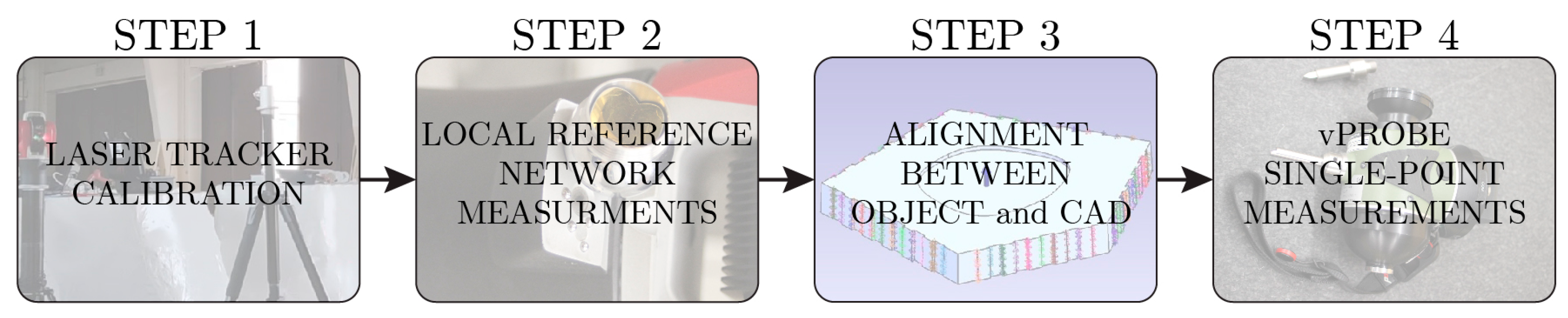
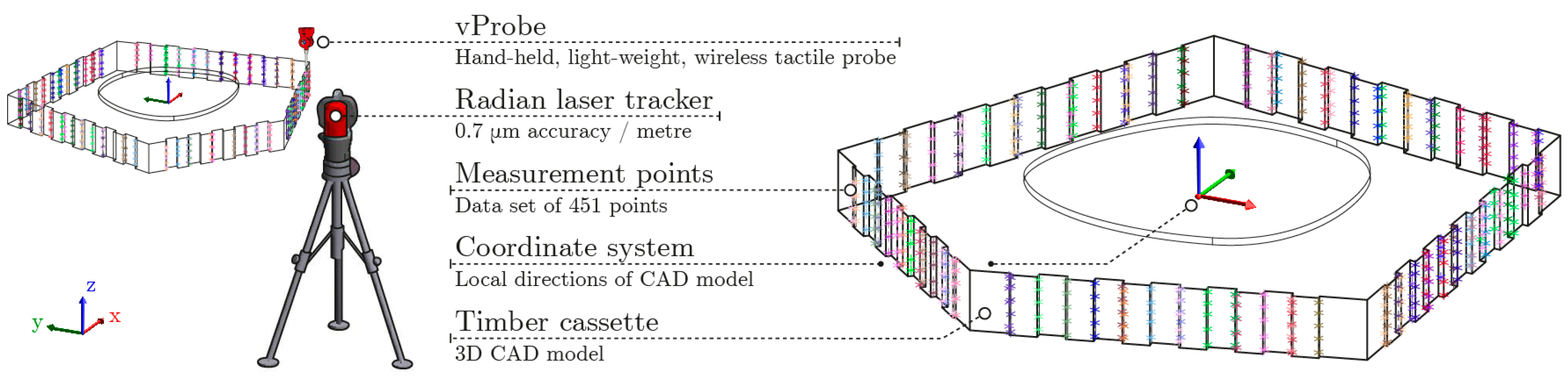
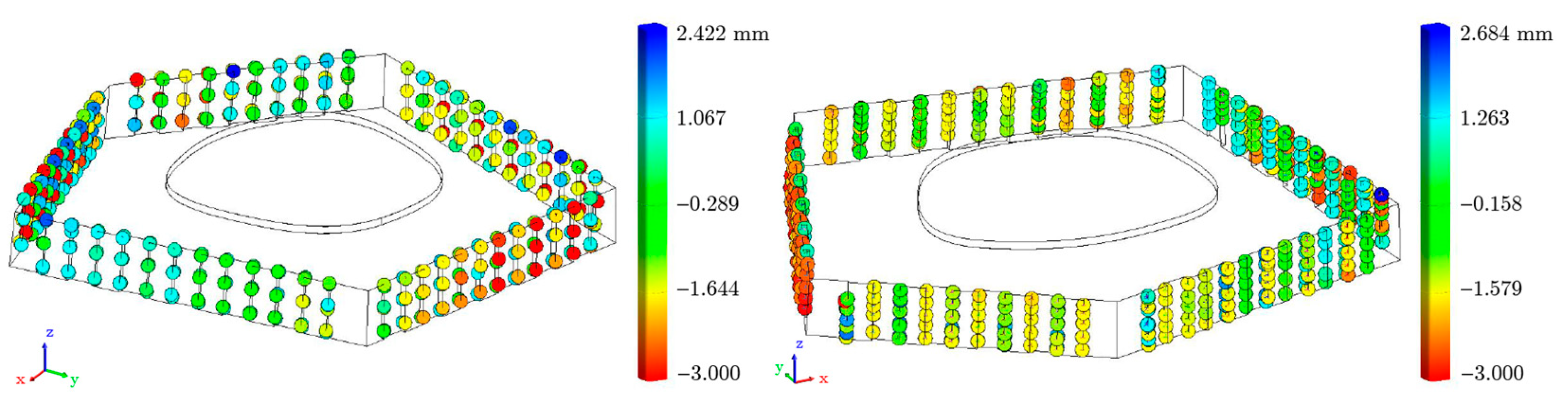
3.2.1. Laser Tracking of Shell Components

Methods

The objective of measuring the shell’s timber components using laser tracking was to obtain an accurate dimensional assessment of their geometric state prior to their reconstruction in 2023, enabling a comparison of the geometry with the first measurements conducted in 2019. Initially, this investigation aimed to compare the same shell segments for both measurement periods; however, restrictions in the schedule of the reconstruction of the BUGA Wood Pavilion in 2023 and the associated limited availability of these shell segments allowed for only one timber cassette, i.e., cassette number 348, to be used for a complete assessment, thus classifying it as a valid specimen. The measurements were carried out using a radian laser tracker in a set with vProbe made by API (Automated Precision Inc., Rockville, MD, USA). This set allows high-precision measurements of geometrically complex object shapes. For both measuring periods, the authors developed a measuring process that enables precise mapping of numerous concealed measuring points and multiple varying angles between the individual surfaces of a timber cassette [51].
When measuring with a laser tracker, ambient environmental conditions can have significant effects on the measurement results, as the employed laser tracker may be highly susceptible to fluctuations in temperature, humidity, or other external influences such as vibrations. The laser tracker measurements on cassette 348 were carried out in February 2023 at approximately 1.6 degrees Celsius in a semi-open factory hall, which was subject to ambient vibrations caused by construction work and heavy machinery. Consequently, not all measured points could be used for a proper analysis during data processing, requiring the entire dataset to be filtered first to remove any measuring noises. Figure 12 illustrates the sequential workflow of the measurement procedure of the timber cassettes using a laser tracker.
The laser tracker and vProbe must be calibrated and georeferenced in a local environment by measuring at least four stable points in its vicinity, which establishes a local coordinate system for all following measurements. In a subsequent step, the object itself must be properly located in relation to the CAD (computer-aided design) model. A conventional prismatic SMR (spherically mounted retroreflector) made by API for laser tracking was used to measure 22 points on the object’s surface to align the planned vProbe measurements with the CAD model [58]. These points were required solely for the described alignment and were not considered during analysis. Following successful alignment, all vProbe measurements were performed using one laser tracker position. Given the ambient environmental conditions, the stability of the device was prioritized to prevent possible shifts when merging datasets from multiple device positions in post-processing mode. This method entailed rotating the timber cassette to obtain all the required points on each of its surfaces. The measuring technique using vProbe is based on the use of additional tips, which form an angle of 90 degrees to the measuring point. In total, 451 points were measured for timber cassette 348. Figure 13 illustrates the measurement setup employed and the final dataset with all measured points.

Results

For both surveys (2019 and 2023) of cassette 348, the data analysis method compares the measurements obtained by laser tracking with the CAD model. The results of these two computations showed a high level of stability of the geometric state of the shell cassette during and in between the two surveys, therefore confirming that no major deviations from the nominal vectors occurred. In this context, however, it is important to note that the points measured on the surface of timber cassette 348 were not identical for the two measurement epochs. This implies that a point-to-point (P2P) comparison between the two datasets using identical points on the surface of the cassette was not possible. Therefore, the datasets of each survey had to be evaluated utilizing a unique reference to the surfaces of the CAD model by computing the normal vector for each point in the dataset using the metrology software Spatial Analyzer 2020. The normal vector can be utilized to compute the point-to-surface (P2S) relation using nominal distances to the surfaces of the CAD model. Figure 14 illustrates the results of the comparison of measured points using a laser tracker with the CAD model for each survey.
The results of the described investigation show that the selected timber cassette 348 is in excellent condition, displaying only minor deviations from the CAD model, provided that prior data filtering is applied and measurement outliers caused by external influences are neglected. A general comparison of the results for both surveys shows that the range of displacements remains approximately constant for each of them, between −3.0 and +2.6 mm, whereby most of the measuring points are in the positive direction. This result is based on the processing of all measured points, prior to data filtering. In addition, this confirms that neither the material nor the shape of the examined shell cassette was significantly damaged or deformed in the period between the individual measuring epochs. Following a multi-step data-filtering process and neglecting major outliers, the mean RMS (root mean square) error of displacements related to the CAD model was 0.30 mm (with a standard deviation (std) of 0.29 mm) and 0.44 mm (std = 0.40 mm) for survey 1 (2019) and survey 2 (2023), respectively. These results fall well below the expected tolerance range and are therefore well within the standard fabrication tolerances defined by DIN 18203-3 [59], which specifies permissible deviations of ±0.2% of the nominal component dimension or a maximum of ±5 mm for wall, arched ceiling, and roof panels.

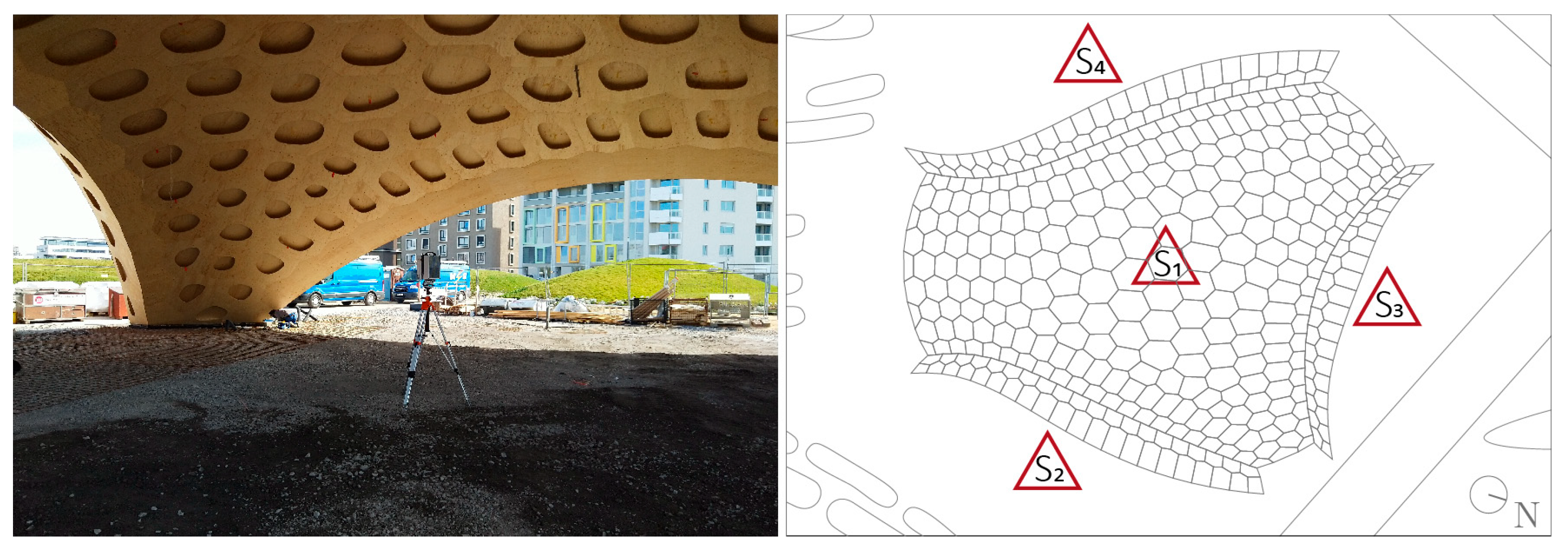
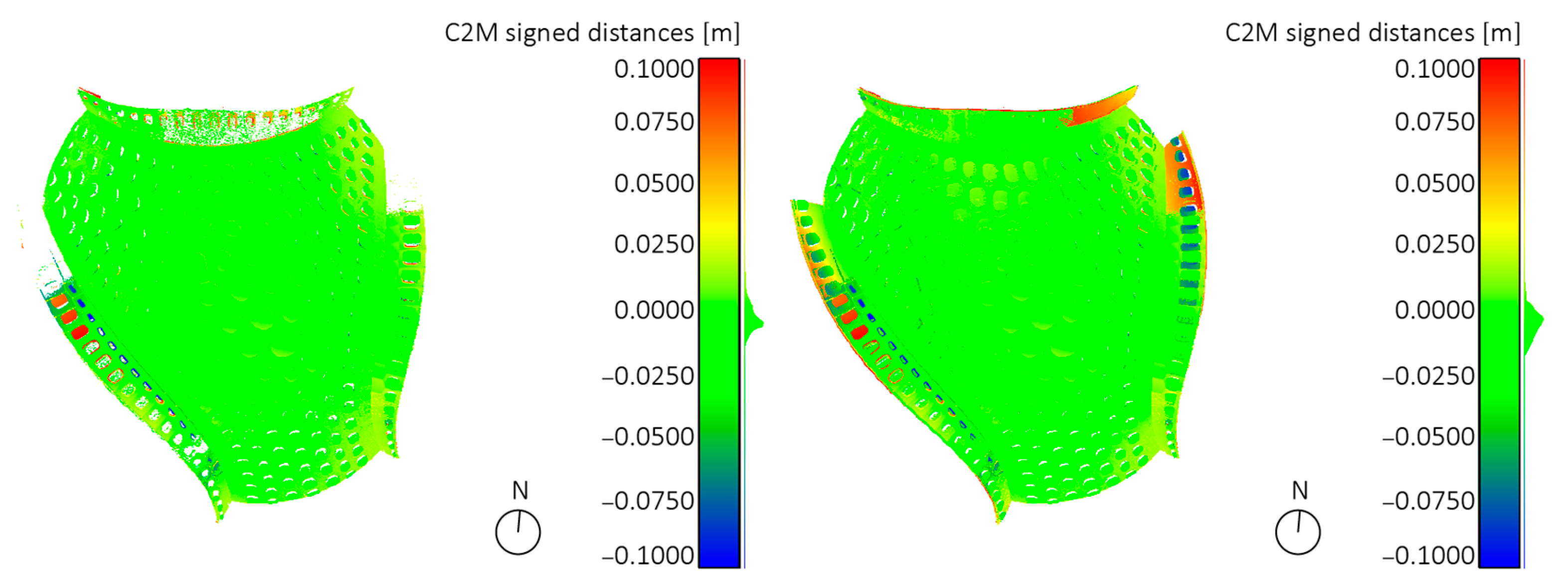
3.2.2. Laser Scanning of the Shell Structure

Methods

The geodetic measurements of the BUGA Wood Pavilion were conducted after its construction in Heilbronn in March 2019, once again during the summer, as well as after its reconstruction in Mannheim in 2023. Terrestrial laser scanning (TLS) was used to create a 3D geometry of the finished shell [60]. The employed laser scanner (model Leica HDS7000, Leica Geosystems AG Heerbrugg, Switzerland) measures horizontal and vertical angles, as well as distances. Such a scan can also be used to calculate the 3D coordinates that represent the so-called point cloud. The measurements were carried out with a resolution of 6.6 mm at a distance of 10 m. The measurement accuracy is 3.1 mgon for the angular measurements, and the noise for the distance measurements is given with an RMS of 0.5 mm at 10 m [61]. Since one single scanner position cannot capture the entire geometry of the shell due to occlusions, measurements from multiple scanner positions are used. One position was chosen in the center of the pavilion to be able to obtain a proper overview of the main body (S1). The other three stations (S2–S4) were located outside the pavilion at the midspan of the shell’s arches to capture them as accurately as possible. Figure 15 illustrates the employed measurement setup.
As all measurements are initially carried out in a local scanner coordinate system, additional black–white targets are distributed in the vicinity of the pavilion, which are used for registration in data processing, enabling all scans to be transformed into the same local coordinate system. Thus, all scans of one survey, i.e., of one measurement day, are located in a joint coordinate system. Once the orientations of all scans are aligned with the orientation of the CAD model, scans of different surveys can be compared and analyzed against the design model. A particular challenge when evaluating the two measurements of the timber shell, however, is to reference the individual measurements to each other. As there were no identical fixed points available for this comparison due to the change in location, the implementation of conventional methods for referencing using identical points proved impossible. Therefore, an initial rough manual alignment of the point cloud to the CAD model needed to be conducted. Subsequently, the iterative closest point (ICP) procedure was applied to align the point clouds [62].

Results

The laser scanner measurements carried out in the different surveys enable comprehensive tracking of the long-term deformations of the timber structure. As wood is a natural building material, changes in geometry may also be observed because of seasonal influences. In this study, however, the focus lies on the potential change in the geometry of the segmented timber shell as a result of its dismantling and relocation. For reasons of comparability, both recordings of the BUGA Wood Pavilion, the first conducted in Heilbronn in 2019 and the second in Mannheim in 2023, were performed in early spring, shortly after the respective assembly of the timber shell. Using the ICP method [62], an RMS of the registration of 4 mm could be achieved. The implementation of cloud-to-mesh (C2M) comparisons of the measured point clouds with the CAD model enabled a thorough analysis of the geometric quality of the timber shell. This comparison identified deviations along the shell arches with a maximum of up to 10 cm for both site locations (see Figure 16).
Furthermore, it could be observed that after its reconstruction in Mannheim in 2023, the BUGA Wood Pavilion exhibited deviations of this magnitude on all three arches, whereas in Heilbronn, deviations of this magnitude only applied to the one arch in the west of the shell, and only at a very localized area. In both surveys, however, the main shell structure of the pavilion showed very small deviations from the nominal value of less than 1.0 mm, which lies significantly below conventional construction tolerances (typically around 10–20 mm).

3.3. Structural Assessment

In 2019, the Materials Testing Institute (MPA) of the University of Stuttgart, Department of Timber Construction conducted tests on the shell segments (hereinafter also referred to as timber cassettes or timber panel elements) and the robotic fabrication process of the BUGA Wood Pavilion. The subject of these investigations was non-regulated, non-standardized robotically fabricated timber compound panel elements and their adhesively bonded joints [63,64,65,66,67]. Furthermore, an expert report [68] on the structural integrity and usability of these cassettes was required by building authorities for construction approval [69] of the timber shell. In 2023, a re-evaluation of the strength and integrity of the bond lines of the dismantled timber cassettes for the relocation of the BUGA Wood Pavilion to Mannheim [70] was performed by MPA, as the basis of an expert report [71] for updated approval in an individual case [72].

3.3.1. Deviations from Normative Regulations

The timber cassettes and the employed robotic fabrication process deviate to varying extents in four main categories from the specifications of the technical building regulations specified in EN 1995-1-1 [73], DIN 1052-10 [74,75], and other relevant building regulations (here: general building authority approvals). 1. The components of a timber cassette, which are made of multi-glued laminated veneer lamellae with cross layers (LVL-C), are not regulated for use in the specific bonded timber panel elements. 2. The use of the adhesive employed for joining the individual components (edge beams and plates) to form a timber cassette is not permissible [72]. Further, the use of the adhesive for the surface bonding of timber components is, in general, limited to a maximum bond line thickness of 0.3 mm, which requires appropriate monitoring and a quality assessment of the robotic fabrication process utilized. 3. The use of a transportable robotic timber construction platform and its integration into standardized industry production for the fabrication of glued timber panel elements is not covered by current standardized regulations or certifications, thus requiring detailed inspection to comply with specified quality standards. 4. The novel robotically bonded joint between the plates and edge beams of a timber cassette obviously requires extensive testing to verify its strength and structural integrity.

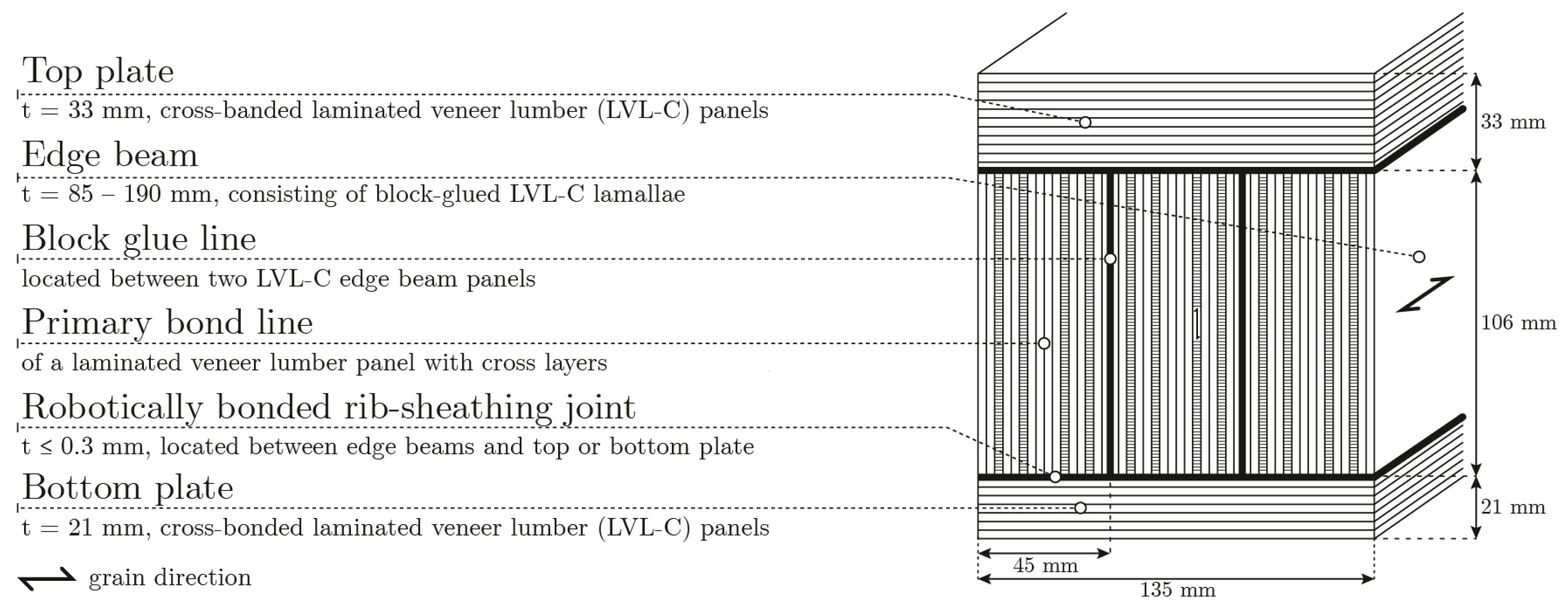
3.3.2. Timber Cassette Components

Methods

A shell cassette of the BUGA Wood Pavilion can be considered as a timber panel build-up, in which the panels and the beams are bonded together utilizing a robotic fabrication setup. These timber cassettes are of polygonal shape, consisting of several edge beams (also referred to as ribs) that follow the circumference of the cassette and are framed by a top and a bottom plate (also referred to as sheathings). Both beams and plates are made of cross-banded laminated veneer lumber (LVL-C) made from spruce wood.
The cross-sectional build-up of the double-skin compound elements is illustrated in Figure 17, indicating the different bond line types. The edge beams are glued to both plates with their veneer layers aligned perpendicular to the plane of the plates, resulting in primary (referred to as a primary bond line in Figure 17) and secondary (referred to as a block glue line in Figure 17) bond lines orientated perpendicular to the plane of the cassette. This means that the cross-plies of the edge beams oriented perpendicular to the beam axis are glued to the plates at their end grain faces.
The edge beams (or ribs) exhibit a cross-sectional depth of 106 mm (in the direction of the cassette thickness) and, prior to their final milling, provided a range of cross-sectional widths from 85–350 mm (in the direction of the cassette plane). The ribs consist of 2–7 bonded laminations of cross-banded laminated veneer lumber LVL-C, specifically laminations of the brand Kerto-Q, in accordance with EN 14734 [76], produced by the company Metsäliitto Cooperative, Metsä Wood, Building Products, Metsä, Finland. The thicknesses of the individual Kerto-Q lamellae composed of one rib are in the range of 40–45 mm, consisting of three (lamella thickness: 44 mm) or four (lamella thickness: 40 mm and 45 mm) cross-oriented veneers running at an angle of 90° to their outer layers. The degree of orthotropy in the plane of lamination (Ʃ thickness transverse layers/Ʃ thickness longitudinal layers) is 0.25–0.4. The rib length varies depending on the size of the timber cassette from about 0.5 to 2.0 m.
The top and bottom plates of a cassette consisted of LVL panels with cross layers (Kerto-Q) in accordance with EN 14734 [76] from the company Metsäliitto Cooperative. The thicknesses of the top and bottom sheathings (LVL-C) were 33 mm and 21 mm, respectively, showing orthotropy ratios of 0.4 and 0.25, respectively. The angles between the longitudinal direction of the edge beams, i.e., of the fiber direction of the longitudinal veneer layers of the respective beam, and the fiber direction of the outer ply layers of the plates (top and bottom), were extremely varied (from 0° to 90°) within individual shell segments due to the alignment with the force flow in the shell structure.
The gluing of individual laminated veneer lamellae to produce the edge beams by so-called block gluing with secondary bond lines, although manufactured in accordance with an expired European Technical Assessment ETA-13/0504 [77], lacked a certificate of usability from the building authorities. In addition, ribs made of LVL-C, such as those employed in the timber cassettes of the BUGA Wood Pavilion, as well as their arrangement at an angle to the fiber direction of the cassette sheathings, are excluded from regulated usability. In addition, the usability of ribs made of multi-glued LVL-C panels was not regulated by DIN 1052-10 and was consequently subject to a building authority usability certificate. To overcome the mentioned regulatory hindrances with regard to the ribs and to assure sufficient structural safety, splitting/cleavage tests according to EN 14374 [76] were performed to verify the bond line quality of the secondary bond lines of the ribs [70]. To do so, a total of 21 cross-sectional slabs (thickness: 75 mm) were cut from six ribs with varying widths ranging from 135 mm to 350 mm (const. depth: 106 mm). Depending on their width, the specimens contained between two to seven secondary bond lines, totaling ninety-one. As specified in [76], the bond lines were split in a wet cold state after two phases of four-hour boil water treatment. As the EN 14374 tests only deliver the wood fracture percentage (WFP) and no quantitative information on strength, additional block shear tests according to EN 14080 [78], Annex D, were performed with dry specimens and pretreated (EN 14374) and redried specimens. The shear strength tests were performed at both the primary bond lines at 0° and 90° fiber orientation (2 × 24 tests) and at the secondary bond lines (28 tests) of the fiber parallel to the glued constituents.

Results

The splitting tests with secondary bond lines showed a majority (71%) of wood fracture percentages (WFPs), fulfilling the requirement of WFP = 70%; the results of the non-compliant specimens were mostly slightly below the required level. The block shear tests did not reveal statistically significant differences between primary and secondary bond lines regarding both shear strength and the WFP [69,70]. In addition, the strength reductions induced by the applied pretreatment of the primary and secondary joints were of the same order of magnitude of about 30% compared to the corresponding values of the dry specimens. The achieved residual strength levels were considered satisfactory. With regard to the absolute strength levels, the 5% quantile values of the dry shear strengths of the primary and secondary joints determined in accordance with [79] were 3.2 N/mm2 and 3.0 N/mm2, respectively. These values are significantly higher than the shear strength parallel to the fiber in flatwise bending fv,0,flat,k = 2.3 N/mm2, as stated in the material’s then-expired Declaration of Performance [80].
In conclusion, the high structural performance of the ribs, specifically their secondary bond lines, could be verified despite deviations from building regulatory specifications. Furthermore, based on a visual inspection of numerous other ribs, there were no striking indications that the sample size of the conducted examinations was unrepresentative. All other material properties of the employed LVL panels, such as tensile and compressive strengths, as well as the stiffness parameters, e.g., modules of elasticity, were used in the design of the shell, with the characteristic values given in [80].

3.3.3. Adhesive

The fiber-reinforced, one-component polyurethane (1C-PUR) adhesive Jowapur 686.70, made by Jowat SE, Detmold, Germany and conforming to German Technical Building Approval (TBA) Z-9.1-800 [81], was used to bond the ribs to the sheathings. The reasons for this were (i) the general environmental friendliness of 1C-PUR adhesives and (ii) the rather long assembly time of the specific adhesive (60 min), which favors the robotic manufacturing process, which takes 12 min per timber cassette for a batch of (on average) four cassettes per pressing operation. However, the use of the chosen adhesive, as well as other 1C-PUR adhesives, for joining the cassette’s individual components is met with interdepending issues that, in principle, rule out their application. DIN EN 1995-1-1/NA [82] and DIN 1052-10 [74,75] standards enable exclusively phenolic and aminoplastic polycondensation adhesives according to EN 301 [83] for ribbed timber panel elements. The reason for the exclusion of structural 1C-PUR adhesives conforming to EN 15425 [84] is bound to their generally low gap-filling properties, which limit their bond line thickness to 0.3 mm for surface bonding [81]. This thickness restriction stems from the adhesive’s pronounced tendency to foam due to CO2 formation during the curing process, resulting in a foam-like adhesive layer containing air and CO2 bubbles that lead to reduced strength and durability. In the case of double-skin panel elements, the inevitable depth tolerances of the multiple ribs in the compound aggravate the fulfillment of these bond line thickness restrictions to a high degree. To ensure structural integrity and high in-plane shear resistance aligned with the membrane-dominated force paths of structurally optimized shells, the BUGA Wood Pavilion employed innovative measures, including high-precision robotic fabrication of the modular cassette system and meticulous manual planing of cassette beams to their nominal height—verified through caliper measurements and continuous factory production control—to achieve sub-millimeter accuracy at the intricately milled finger joints and a minimal adhesive interface thickness of less than 0.3 mm between cassette ribs and sheathings [51,52]. In addition, the short rib lengths (0.5–2.0 m) helped to mitigate this issue compared to conventional timber panel elements featuring rib lengths of between 5–20 m. To enable the use of the selected 1C-PUR adhesive, despite the mentioned technical and regulatory restrictions, extensive investigations on bond line strength and durability (summarized in Section Results in Section 3.3.4 ) were required to obtain building authority approval.

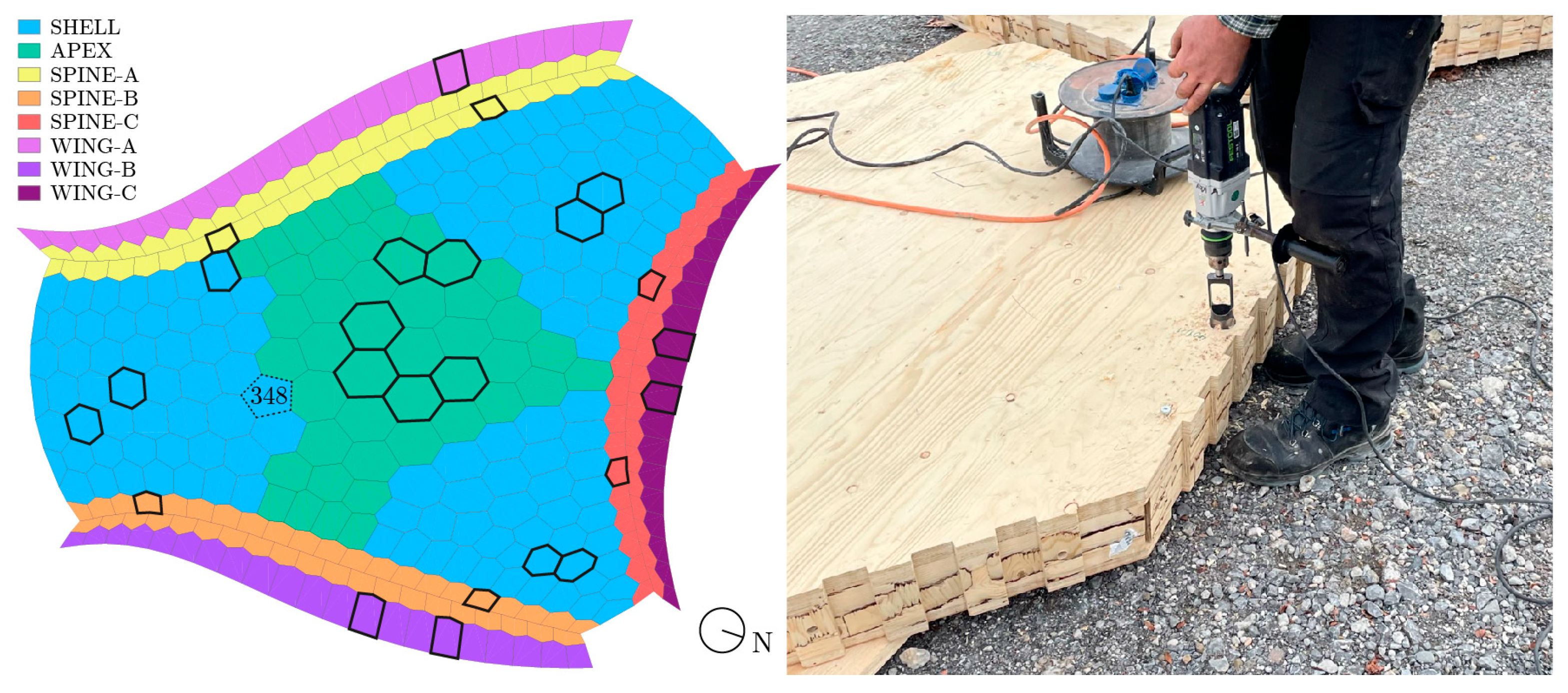
3.3.4. Robotic Fabrication and Workshop Implementation

Methods

The fabrication of the timber cassettes of the BUGA Wood Pavilion primarily utilizes a transportable robotic timber construction platform comprising two six-axis robots and a two-axis positioner (see Figure 18, left). The fabrication process entails the assembly of a cassette, including all lifting and positioning procedures of its components, adhesive application, and the machining of its final geometry [36,39,52]. In the first step, the bottom sheathing plate is placed on the two-axis positioner, using vacuum grippers as a fixation mechanism.
Once the plate is positioned, the adhesive is applied to the upper side of the bottom plate in the form of a bead application (see Figure 18, right). The application head features eight rows of beads, each 10 mm wide, resulting in a comb width of 80 mm and an adhesive mass per area of 240 g/m2. Multiple parallel application tracks are laid, depending on the rib width to be bonded (up to 350 mm). Subsequently, the edge beams are placed and secured in position using beech wood nails robotically inserted from below. In the next step, the adhesive is robotically applied to the top side of the ribs, followed by the placement of the top sheathing plate and its fixation by beech nails. Finally, one of the robots removes the assembled “raw” cassette from the two-axis positioner to a customized pressing device (as shown in the left image of Figure 18, marked by a triangular symbol) to cure the bond lines.
In one pressing process, several (generally four) timber cassettes with unequal edge contours are arranged above one another in the press device, separated by load-distributing cross-laminated timber (CLT) panels. Hereby, a maximum assembly time of 60 min, specific to the adhesive product used, had to be considered until full pressure application (minimum press time: 150 min). As the sizes of the individual shell segments varied considerably, the cassettes were organized into groups of comparable size. The CLT panels apply surface pressure to each timber cassette by utilizing two opposing hexagonal steel frames, pre-tensioned by six steel rods using a torque wrench. Depending on the element size and/or area surface of the edge beams, the applied pressure ranged from 1.0–1.4 N/mm2. Once the bonded joints of a timber cassette had cured, the robotic fabrication platform machined the cassette to its final geometry.
The robotic fabrication process of the shell cassettes is not covered by current standardized regulations or certifications. However, the robotic application of the adhesive and the pressing process described are not in conflict with any relevant regulations, essentially fulfilling the requirements for proper bonding in accordance with DIN 1052-10 [74,75], except for the employed adhesive. However, in order to obtain approval for individual cases, the implementation and use of the robotic platform for manufacturing shell segments in the workshop of the timber construction company required a comprehensive inspection and an elaborate quality assurance concept according to DIN 1052-10.

Results

In the autumn of 2018, bonding experts of the MPA of the University of Stuttgart verified the fundamental suitability of the robotic fabrication process at the workshop of the manufacturing company müllerblaustein Holzbau GmbH, Blaustein, Germany, in the context of the production of two prototype timber cassettes. During the manufacturing of these two cassettes, the essential requirements specified in DIN 1052-10 with regard to bonding operations, equipment, and staff skills, as well as the provision of the adhesive’s technical data sheet (TDS), were met to a high degree [81].
Firstly, a check of the staff’s skills regarding monitoring and documenting the bonding operation was complemented by the approval of a fully automated digital monitoring and recording process for applying the adhesive on both plates and ribs. The quantity of adhesive applied was determined using the delivery rate of the adhesive pump and the quantity of adhesive collected in a container over a certain period. According to the analyzed records, the adhesive application quantity consistently resulted in a target application quantity of 240 g/m2. Secondly, the continuously measured and recorded climate (temperature) in the workshop areas of production and curing conformed with the normative requirements (>18 °C) throughout the process. In conclusion, the transportable robotic timber construction platform, its implementation in the manufacturer’s workshop, and its manufacturing process were assessed as suitable for the production of timber cassettes for the BUGA Wood Pavilion.

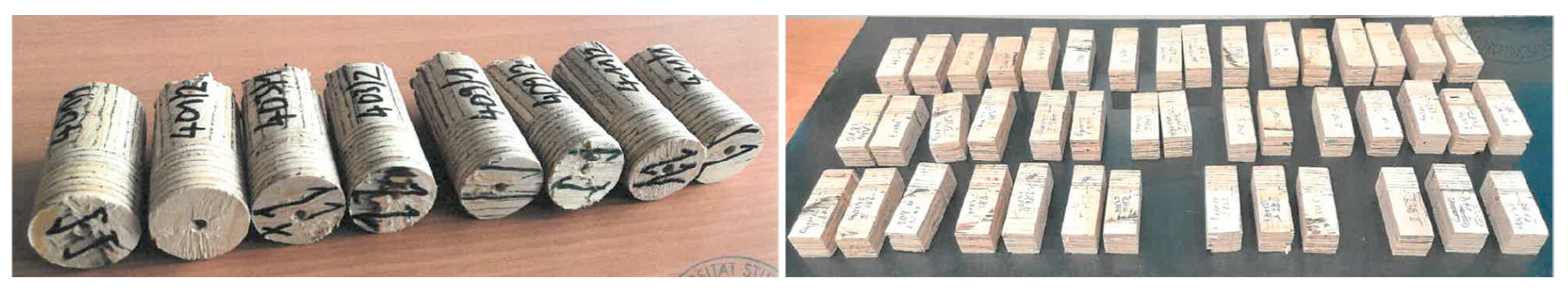
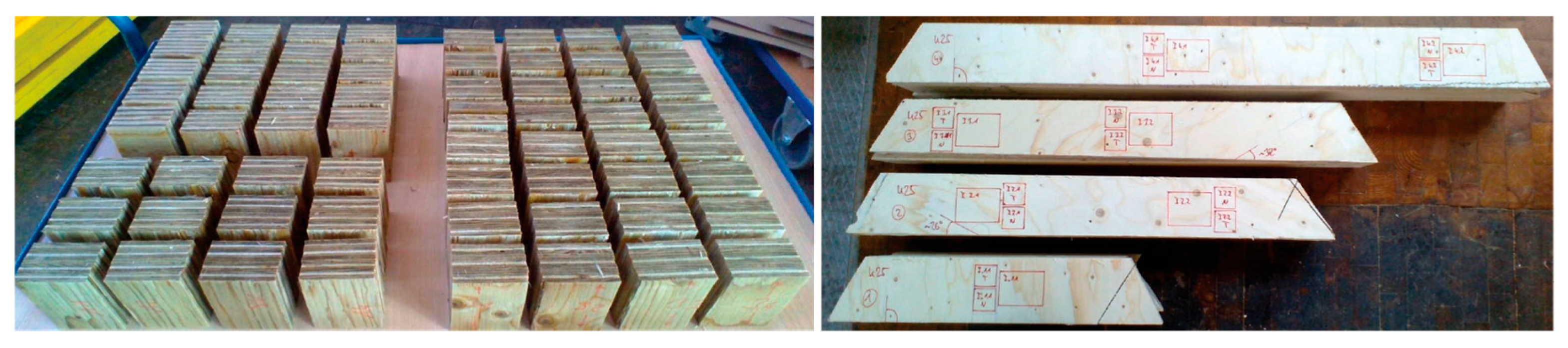
3.3.5. Robotically Bonded Joints

Methods

In 2019, the MPA of the University of Stuttgart conducted three test series on the timber cassettes of the BUGA Wood Pavilion to assess their structural integrity. In 2023, in the context of the pavilion’s relocation from Heilbronn to Mannheim and the realized continued use of the shell, which was initially declared as a temporary structure, a further assessment of the robotically bonded joints was deemed necessary for another approval in individual cases. The new investigations should provide a comprehensive understanding of eventual bond line degradation, proving whether the robotically manufactured joints still provide sufficient residual strength and integrity.

BUGA Wood Pavilion 2019

In the first test series [65], a total of nine ribs with sheathings on both sides were cut from two cassettes, manufactured prototypically in the presence of the MPA [64]. The width of the ribs was 135 mm with one exception (350 mm). The angle φ between the rib axis and the fiber direction of the bonded outer veneer of the sheathings varied from 0° to 90°. The sheathed ribs were then sawn into 17 cleavage specimens with a width of 75 mm (EN 14374 [76]). Further, from both sides adjacent to each of these specimens, a total of 34 block shear specimens with top and bottom sheathing were cut (shear area of 50 mm × 50 mm). The block shear specimens were tested with the same number (17) of samples that were dry without pretreatment and after pretreatment (EN 14374), as well as after subsequent redrying. Due to the presence of both top and bottom sheathings, a total of 68 bond lines (2 × 34) could be tested. In the second test series [66], a total of 12 cleavage tests (EN 14374) were performed with six specimens cut from five ribs of a regularly manufactured cassette with sheathings on both sides. These tests were required as the first test series yielded partially inadequate results in the cleavage tests. In the third series [67], a total of 22 drill cores were extracted from 10 regularly robotically manufactured cassettes of different sizes. The drill cores were taken from the shell segments from various edge positions within the panel elements. The angle φ between the rib axis and the fiber direction of the sheathings varied between 0° and 85° (whereas the first examination exhibited a maximum value of φ = 90°). Prismatic block shear specimens with a nominal area of 25 mm × 25 mm were cut from the drill cores. In contrast to the first test series, the specimens were now tested exclusively without pretreatment for reasons of time and cost.

BUGA Wood Pavilion 2023

For the relocation of the BUGA Wood Pavilion in 2023, the quality (bond line thicknesses, shear strength, and WFP) of the robotically bonded joints of a representative number (24) of shell segments was verified quantitatively by drill core tests. Six cassettes were chosen from the central part of the shell with the lowest roof inclination. Further, seven cassettes were selected from the highly stressed compression arches of the shell (splines A, B, and C) and five cassettes were taken from the outer wings A–C, which were investigated previously in 2019 (Figure 19, left). From each of the chosen cassettes, two to four drill cores were taken (Figure 19, right), totaling 66 samples. In addition, extensive moisture measurements were performed on these samples to determine their wood moisture content (MC) using the oven-drying method [85].
All cores were taken from the top side of the shell segments hereby not interfering with their later reuse by covering them with a rainproof membrane afterward. The drill cores were then processed to block shear specimens with a shear area of 25 mm × 25 mm (see Figure 20). The angle between the rib axis and the fiber direction of the bonded sheathing veneer varied from 0° to 89°; however, in most cases, the angle was less than 30°. Half of the specimens were tested dry without pre-conditioning (moisture content 11.8%, COV 17%), and the other half were tested after boil water treatment (EN 14374) and subsequent redrying at 60° C.

Results for BUGA Wood Pavilion 2019

  • First test series
The measurements of the bond line thickness at different locations of various arrangements of ribs and sheathings predominantly revealed joint thicknesses of 0.2 mm ≤ tb ≤ 0.25 mm. A single individual value of 0.32 mm slightly exceeded the maximum permissible bond line thickness of 0.3 mm. The shear strengths of both dry and redried specimens (shear area 50 mm × 50 mm) revealed a clear relationship with the angle φ between the rib axis and the fiber direction of the bonded (outer) sheathing veneer, as anticipated. The moderately correlated linear regressions evolved as follows:
f v , d r y , 50,2019 φ = 0.026   · φ + 5.28   [ N/mm 2 ] ( R 2 = 0.52 ) ,
f v , r e d r y , 50,2019 φ = 0.028 · φ + 4.61 [ N/mm 2 ] ( R 2 = 0.61 ) .
Equations (1) and (2) reveal an (i) almost equal strength dependency on angle φ and (ii) a significant offset of the pretreated specimens towards lower strengths. The following quantitative discussion of the results relates in terms of conciseness to the strengths at φ = 0° and φ = 90°, as specified in Table 1. For clarity, it should be recalled that in the case of φ = 0°, the rib axis and its respective fiber direction are parallel to the fiber direction of the bonded outer LVL sheathing layer, whereas φ = 90° indicates that the sheathing fibers are oriented perpendicular to the beam axis.
Firstly, it can be observed that the scatter of the results, denoted by the corresponding coefficient of variation (COV), is significantly, i.e., more than two-fold, higher in the case of cross-layered bonded interfaces (φ = 90°) compared to fiber parallel bonding (φ = 0°). Secondly, the result scatter is 1.30 to 1.5-fold higher in the case of the redried specimens in comparison to the specimens without pretreatment. The absolutely very high COVs of the cross-layered bond line interfaces of about 30% and 40% for the dry and redried specimens impact the derived characteristic, i.e., 5% quantile values, based on EN 14374 [76], and assumed normal distributions that were significant yet still tolerable (see below). The dry specimens revealed, at φ = 0°, mean and characteristic values of 5.18 N/mm2 and 3.91 N/mm2, respectively. At φ = 90°, the respective fv,90,dry,mean and fv,90,dry,0.5 strengths were 3.04 N/mm2 and 1.57 N/mm2, respectively, being 40% and 60% lower. The obtained 5% quantile values exceed the characteristic shear strengths in flatwise bending parallel samples and perpendicular to grain samples, with fv,0,flat,k = 1.3 N/mm2 and fv,90,flat,k = 0.6 N/mm2 specified in the manufacturer’s Declaration of Performance (DoP) [86] in extreme manners by factors of 3.0 and 2.6, respectively.
The effect of the chosen harsh boil water pretreatment, which is not reflected by the DoP, can be summarized as follows. In the redried state, the mean strengths at φ = 0° and φ = 90° showed reductions of about 10% and 30% compared to the dry state, respectively, within the admissible range given in the draft of DIN 1052-10 [74,75]. At the characteristic level, the respective reductions associated with pretreatment amounted to about 20% and 45% for φ = 0° and φ = 90°, respectively. Hence, the fv,0.5 values obtained for the pretreated specimens still exceeded the dry-state samples, with the characteristic strengths fv,k of the DoP being higher by factors of 2.3 (fv,0,flat,k) and 1.4 (fv,90,flat,k), respectively. Figure 21 (left) shows the sheared secondary joints (block glue lines) of four sections of each of the three selected edge beams of the timber shell. Figure 21 (right) shows the rib-sheathing segments cut from one of the two prototype cassettes.
The complementary cleavage tests of the first 2019 test series for one of the two prototypes consistently delivered wood fracture percentages (WFPs) that were compliant with the normative requirements for dry specimens. In this context, it should be noted that there are no normative specifications for the required percentage of wood fiber fractures after pretreatment for the investigated different joint constellations. In this case, the requirements were set in accordance with EN 14374 to 70%. For the second prototypical shell segment examined, some of the cleavage results for the bond line between the rib and the bottom sheathing plate (thickness: 21 mm) were significantly below the specified requirement. Consequently, these results necessitated the repetition of tests, which were undertaken in a second 2019 test series and reported below.
In summary, the wood fracture percentages (WFPs) in the dry and redried test specimens were predominantly (74%, i.e., 50 of the 68 samples) excellent. Regarding the correlation between WFPs and shear strength (fv), it should be emphasized that most of the dry and redried tested shear surfaces complied with the combined fv-WFP-criterion in EN 14080 [78]. It should be noted, however, that the fv-WFP-criterion, according to DIN EN 14080, technically only applies to glued joints of fiber parallel-bonded softwood components made of glued laminated timber.
  • Second and third test series and the expert report
The second 2019 test series was exclusively performed with cleavage specimens and was necessitated by the non-conforming results of the first test series. It provided WFP results complying with the requirement of a minimum of 70%; almost all (11/12) showed a WFP of 100%. This is consistent with the obtained thin bond line, which showed an average thickness of 0.17 mm with an extreme value of 0.25 mm.
In the third test series [67], the individual values of the bond line thickness measurements ranged from 0.1–0.2 mm and were consequently consistently below the maximum permissible bond line thickness of 0.3 mm. The achieved shear strengths were in the range of 8.97 to 1.93 N/mm2, depending on the angle of φ between the longitudinal axis of the ribs and the fiber direction of the outer veneer layers of the sheathings. The shear strength–fiber angle relationship can be obtained from the following linear approximation:
f v , d r y , 25,2019 φ = 0.071   · φ + 7.66 [ N/mm 2 ]
This revealed a rather high R2 value of 0.74. The correlated wood fiber percentages were predominantly (20 of 22) very high and higher than 70%. A comparison of the dry shear strengths obtained in test series I and III, differing in shearing length and area by factors of two and four, respectively, revealed average values that were 1.35 times higher for test series III, with smaller shearing dimensions for the angle range of 0°≤ φ ≤ 30°, comprising most of the specimens. This relates to a Weibull size effect exponent ksize = (Aref/A)1/m of 1/m = 0.22 (shearing areas: Aref = 50 × 50 = 2500 mm2; A = 25 × 25 = 625 mm2). The derived size effect exponent states a very reasonable number for shear strength issues in timber construction (note: in the case of employing shearing length exclusively, a much higher size exponent of 1/m = 0.43 evolves).

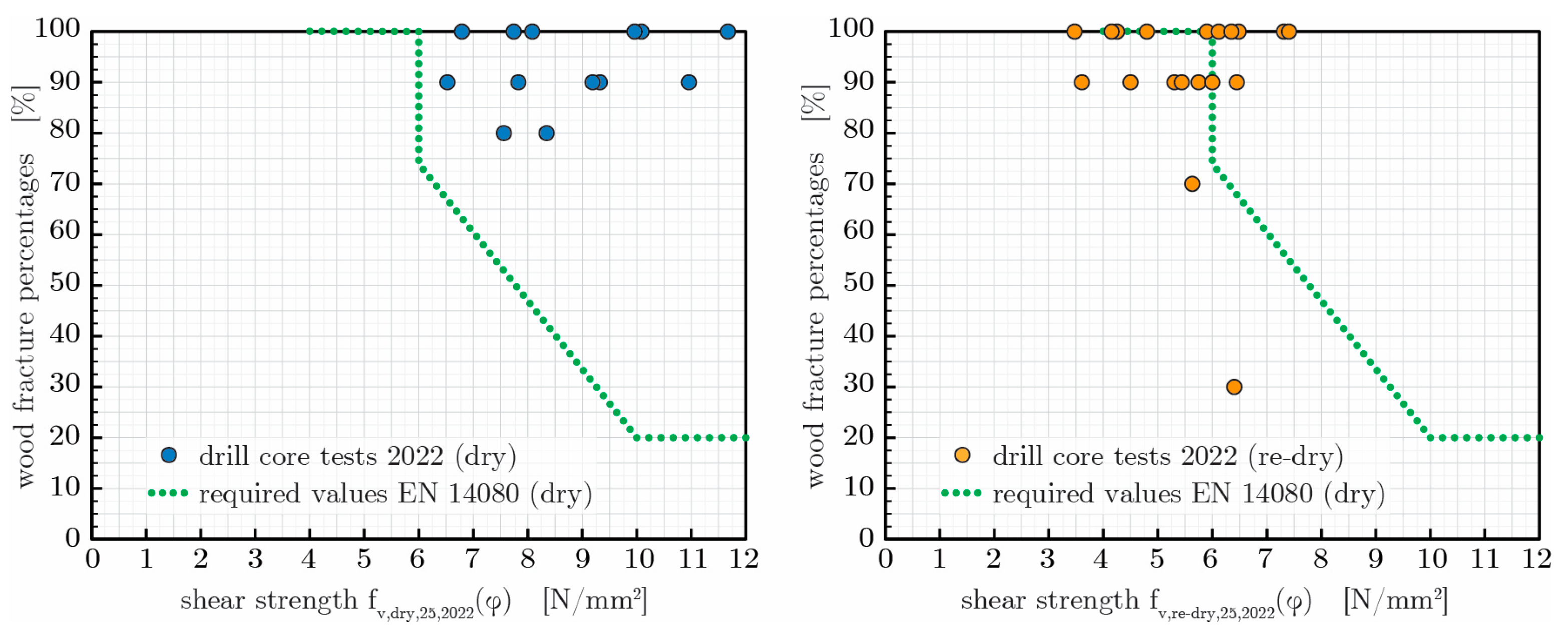
Results for BUGA Wood Pavilion 2023

Equations (4) and (5) reveal the linear approximations of the shear strength–fiber angle relationships obtained in the 2022 residual bond line resistance tests for the untreated dry and the pre-conditioned redried specimens:
f v , d r y , 25 , 2022 φ           = 0.086   · φ + 8.93 [ N/mm 2 ] ( R 2 = 0.55 ) ,
f v , r e d r y , 25 , 2022 φ = 0.032   · φ + 5.77 [ N/mm 2 ] ( R 2 = 0.26 ) .
The equations show a significantly smaller impact of angle φ for the pretreated specimens, together with a reduced strength level. To enable a concise quantitative discussion, the strength results for the various angles φ between the rib axis and the grain direction of the sheathing are condensed in Table 2 into two ranges of φ = 0–15° and φ = 16–90°. The mean and characteristic (5% quantile) strengths of the pretreated specimens revealed in the angle range of φ = 0–15° significant reductions of about 40% compared to the untreated samples. A much lower articulate strength drop of 20% can be noticed in the range of 16° ≤ φ ≤ 90° for the mean value level, whereas the 5% quantiles do not differ.
The correlation of the wood fracture percentages with the bond line shear strengths, representing besides delamination tests the most important assessment criterion for bond lines, e.g., in glued laminated timber (GLT), is depicted in Figure 22. The graphs also show the stepped requirements specified in EN 14080 [78], Table 10, for dry softwood GLT specimens (6% ≤ MC ≤ 15%). It is apparent that the untreated specimens comply entirely with the requirements, whereas the pretreated specimens are predominantly below the level required for the untreated specimens. This is mostly due to reduced strength values in the range of about 4–6 N/mm2. In the absence of any standardized regulations for the fv-WFP correlations of pretreated specimens, the authors considered the results to be sufficient. This assumption was especially fostered by the fact that almost no shear strength results fell below 4.0 N/mm2, which is stipulated in [78] as the lower boundary for dry GLT bond lines.
The wood moisture content (MC) measurements revealed that the decisive MC values (mean and maximum) occur in the region of the shell wings and spines (see Figure 19, left). As the double-skin cassette elements provide a large opening in their bottom plates, the maximum moisture input from rain in strong winds is to be expected at these locations. Based on all MC values obtained from the oven-drying method, the mean value of 11.8% at the time of sampling in autumn 2022 can be considered low for a building classified in service class 2. As all values of the investigated samples were well below 20%, a moisture-induced reduction in load-bearing capacity can be ruled out. In addition to the MC measurements carried out on the drill cores, the wood moisture content was measured as part of the pavilion’s dismantling in late 2022, using a hand-held, electrical wood MC-measuring device. The findings obtained from these measurements show that the exterior support areas of the shell structure exhibited MC levels scattered close to the fiber saturation point (>25%) in the near-surface areas of the ribs of the cassettes. In addition, electrically measured wood moisture levels above 20% were found at isolated locations in the regions of the northern (SPINE-C) and western (SPINE-A) wing and spine, in which the openings of the bottom plate of the timber cassettes have potentially been exposed to heavy rain and gusts of wind (for an indication of the cardinal orientation of the BUGA Wood Pavilion, see Figure 19).

Comparison of Initial (2019) and Residual (2022) Bond Line Tests

An accurate comparison of the residual shear strength tests should ideally be based on samples with identical shear lengths and areas to eliminate dimensional influences. This is stringently possible only for the block shear results fv,dry,25,2019(φ) from the non-pretreated specimens of the 2019 test series III [67], see Equation (3), vs. the strengths fv,dry,25,2022(φ) of the 2022 residual bond line capacity verifications [70], comprising Equation (4) and Table 2. Both investigations relied on shear areas of 25 mm × 25 mm. In the angle range of 0 ≤ φ ≤ 30°, comprising most of the specimens of both series, the 2022 residual shear strengths were, on average, 15% higher compared to fv,dry,25,2019,mean. This proves that no bond line degradation evolved during the three years of the structure’s service life at the Heilbronn site. This can also be ascertained on the basis of the pretreated test specimens.
To do so, the shear area difference between test series I of 2019 and the 2022 residual strength test is corrected roughly by the above-derived size effect for the dry specimens. Applying a size effect factor of 1.36 to Equation (2) yields an average absolute deviation from the 2022 results, Equation (5), of around 5%, hence proving a comparable order of magnitude to the results of the initial tests from 2019.

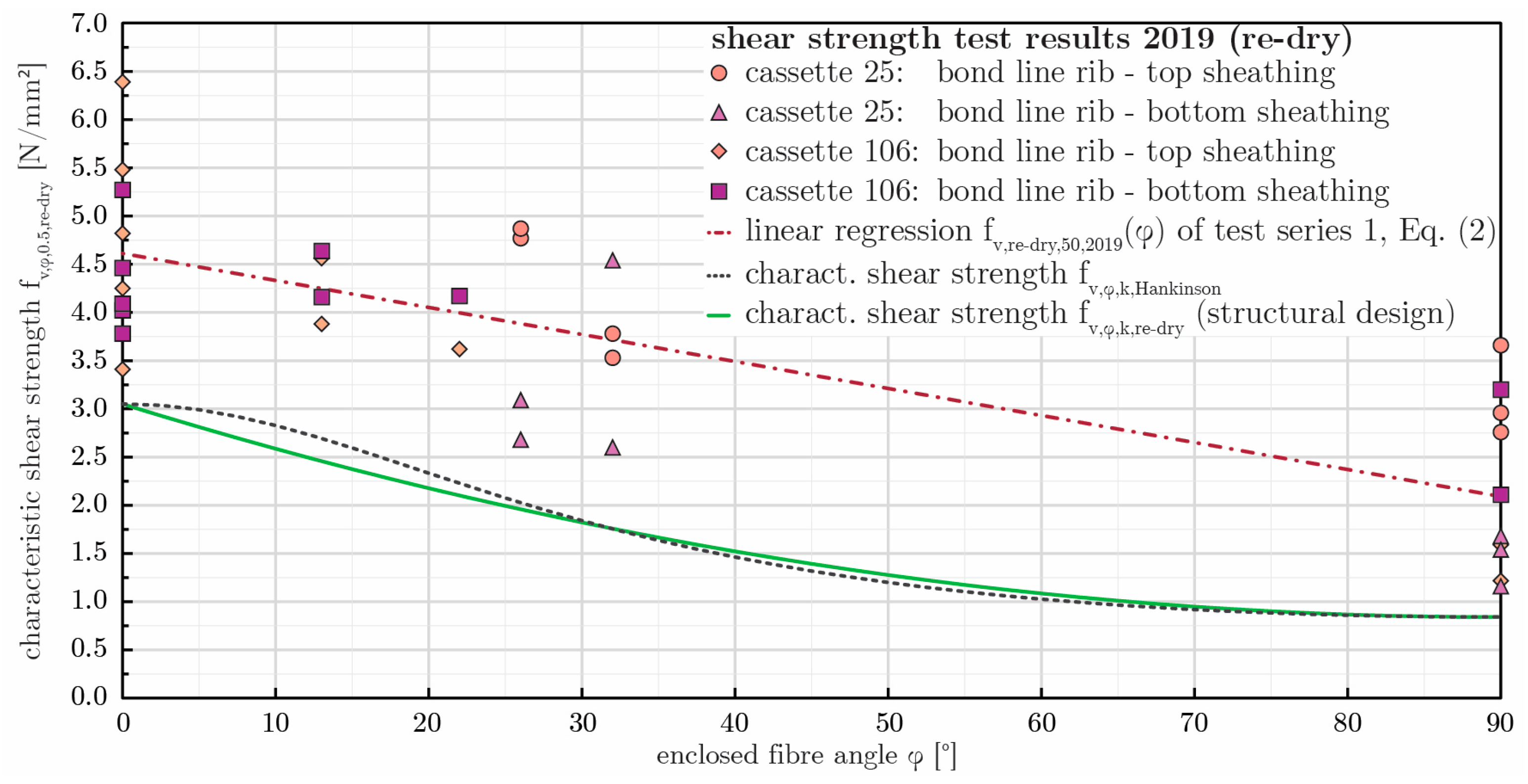
Derivation of Characteristic Bond Line Shear Strengths for Structural Design

For the structural design and analysis of the BUGA Wood Pavilion, a complex finite element model was developed, as described in [38]. To ensure the structural integrity of the adhesive joints in the timber shell, the maximum membrane shear stress between the ribs and the sheathings of the cassettes, denoted as τxy, was used for verification. The analysis of the adhesive joint did not differentiate between the bond line between the top or bottom plate and rib; instead, the respective minimum and maximum values of τxy were considered. A closed-form equation for the characteristic shear strength over the entire angle range of φ = 0–90° was required for the verification of the bond line strength of the robotically bonded joints.
In this context, making use of the panel shear strengths specified in the DoP [86] for fiber directions 0° and 90° as stipulated by DIN EN 1995-1-1/NA, NCI NA. 11, was considered too conservative, as these values (fv,0,flat,k = 1.3 N/mm2, fv,90,flat,k = 0.6 N/mm2) do not mirror the actual interface characteristics. Hence, it was decided to employ the characteristic shear strengths obtained in the first 2019 test series (see Section Results for BUGA Wood Pavilion 2019 in Section 3.3.5) with pretreated and redried specimens. In detail, the 5% quantile values, as given in Table 1, were used as cornerstones at φ = 0° and φ = 90° for fv,φ equations safely enclosing the test data. The approximations by Hankinson [87], Equation (6), and a parabolic interpolation, Equation (7), are denoted by
f v , φ , k , H a n k i n s o n = f v , 0 f v , 0 f v , 90 · sin 2 φ + f v , 90 · cos 2 φ [ N/mm 2 ] ,
f v , φ , k , p a r a b o l i c   = f v , 0       f v , 90   ·   φ 90 2 90 2 + f v , 90 [ N/mm 2 ] ,
where fv,0 = fv,0,re-dry,0.5 = 3.05 N/mm2 and fv,90 = fv,90,re-dry,0.5 = 0.84 N/mm2 yielded almost coinciding fv,φ,0.5 approximations. Finally, the parabolic fit (Equation (7)) was chosen for the structural design of the timber shell, as it was more conservative in the angle range of 0° to 40°. Figure 23 depicts the test data, the linear mean strength level approximation according to Equation (2), and the discussed nonlinear fv,φ,0.5 curves.
With regard to the bond line design verification, in conjunction with the relocation of the BUGA Wood Pavilion to Mannheim, it was questioned whether the previous 2019 Equation (7) for fv,φ could still be used unmodified. As the necessitated verification tests in 2022 proved, as shown above, that no apparent bond line strength degradation had occurred, which was then confirmed in an expert report [71], it was deemed justified to perform the bond line design with the previously used approximation (Equation (7)) for fv,φ,k, together with the cornerstone values of fv,0,re-dry,0.5 = 3.05 N/mm2 and fv,90,re-dry,0.5 = 0.85 N/mm2 for φ = 0° and φ = 90°, respectively. The design shear strength values were derived as stipulated by [73] on the basis of a modification factor for a duration of load and moisture content kmod = 1.0 (for LVL and short-term/instantaneous load duration classes), as well as by a partial factor for material properties γM = 1.3, also accounting for model uncertainties and dimensional variations.

4. Conclusions

In response to the increasing demand for housing and the imperative to address climate change through sustainable construction practices, this research explores the methodology of Co-Design for circular construction as a viable approach. This study highlights the potential of modular lightweight timber construction and advanced quality assessment methods as essential components for the circular use of building systems and materials in architecture.
The primary problem statement revolves around the feasibility and effectiveness of segmented timber shells as reusable timber structures, focusing on their non-destructive dismantling and reconstruction while maintaining their structural integrity and aesthetic quality. Utilizing an integrative structural design and engineering methodology, as well as advanced and state-of-the-art quality assessment methods, the authors demonstrate that such structures are robust and can be effectively reused, contributing to circular construction practices. The investigations were exemplified by the BUGA Wood Pavilion, which serves as a research demonstrator and a proof of concept for the successful realization of segmented timber shells as reusable constructions.
Through a series of various quality assessments, including visual, geodetic, and structural investigations, the findings reveal that the modular timber system maintains its structural performance over time, despite variations in moisture content and long-term geometric deviations, validating the effectiveness of modular, reusable timber structures and their potential application in sustainable construction. In addition, the presented research demonstrates the successful implementation of novel transportable robotic timber construction platforms to provide suitable solutions for producing complex lightweight timber structures. While acknowledging that segmented timber shells are primarily suited for wide-span roof structures and do not directly address the broader housing crisis, the methodologies and results from this study are deemed transferable to other forms of modular timber construction.
Improvements to enhance the sustainability of reusable timber structures include the consistent use of local resources, the integration of construction principles for prolonging their service life, and planning efforts to ensure adequate supervision and monitoring during their relocation. In addition, the inclusion of possible extensions in the design of modular structures can further increase their versatility and longevity. As part of ongoing research within the Cluster of Excellence IntCDC at the University of Stuttgart, future work will advance Co-Design strategies for sustainable and circular construction through integrative design frameworks that incorporate reuse-oriented methodologies, enhanced quality assessment, and life cycle assessment (LCA) and life cycle costing (LCC), pursued in close interdisciplinary collaboration between academic and industry partners to strengthen circular practices in timber architecture.
Overall, this study contributes to a broader understanding of sustainable construction by demonstrating the viability of modular timber structures and circular building practices, emphasizing the robustness of co-designed timber constructions that can meet the challenges of the future built environment.

Author Contributions

Conceptualization, S.B., S.A., L.G., L.B. and M.G.; Data curation, S.B., S.A., L.G. and L.B.; Formal analysis, S.B., S.A., L.G. and L.B.; Funding acquisition, V.S., A.M. and J.K.; Investigation, S.B., S.A., L.G. and L.B.; Methodology, S.B., S.A., L.G., L.B. and M.G.; Project administration, S.B. and M.G.; Resources, S.A., V.S., A.M. and J.K.; Software, S.B., S.A., L.G. and L.B.; Supervision, V.S., A.M. and J.K.; Validation, S.B., S.A., L.G. and L.B.; Visualization, S.B., S.A., L.G. and L.B.; Writing—original draft, S.B., S.A., L.G. and L.B.; Writing—review and editing, M.G., V.S., A.M. and J.K. All authors have read and agreed to the published version of the manuscript.

Funding

The work presented in this paper was funded by the State of Baden-Wuerttemberg, the European Regional Development Fund through the ‘Holz Innovativ Programm’-EU EFRE/BW 501210, the Baden-Württemberg Stiftung in Stuttgart (Germany), the Bundesgartenschau Heilbronn 2019 GmbH, the Bundesgartenschau Heilbronn 2023 GmbH, and the GETTYLAB. It was partially supported by the Deutsche Forschungsgemeinschaft (DFG, German Research Foundation) under Germany’s Excellence Strategy-EXC 2120/1–390831618.

Data Availability Statement

The data presented in this study are available on request from the corresponding author due to the research still being in progress and therefore requiring restricted dissemination.

Acknowledgments

The authors would like to express their gratitude towards their fellow investigators, Martin Alvarez, Urs Basalla, Abel Groenewolt, Oliver David Krieg, Ondrej Kyjanek, Hans Jakob Wagner, the BUGA GmbH (Oliver Töllner and Hanspeter Faas), and Müller Blaustein Holzbauwerke (Reinhold Müller†, Daniel Müller, Bernd Schmidt, and Oliver Fried). We also thank Jowat GmbH (Ralph Kirst and Michael Wolf) and Niemes Dosiertechnik GmbH (Volker Niemes) for continuous consultation and tests.

Conflicts of Interest

The authors declare no conflicts of interest.

Abbreviations

The following abbreviations are used in this manuscript:
ITKEInstitute of Building Structures and Structural Design, University of Stuttgart
MPAMaterials Testing Institute, University of Stuttgart
ICDInstitute for Computational Design and Construction, University of Stuttgart
IIGSInstitute of Engineering Geodesy, University of Stuttgart, Germany
IntCDCIntegrative Computational Design and Construction for Architecture
STSSegmented timber shell
BUGAFederal Horticultural Show (in German: Bundesgartenschau)
LVLLaminated veneer lumber
APIAutomated Precision Incorporated
CADComputer-aided Design
SMRSpherically Mounted Retroreflector
P2PPoint-to-point
P2SPoint-to-surface
RMSRoot Mean Square
stdStandard deviation
TLSTerrestrial laser scanning
C2MCloud-to-mesh
MPAMaterials Testing Institute
LVL-CLaminated veneer lamellae with cross layers
WFPWood fracture percentage
1C-PURFiber-reinforced, one-component polyurethane
TBATechnical Building Approval
CLTCross-laminated timber
TDSTechnical data sheet
MCMoisture content
COVCoefficient of variation
DoPDeclaration of Performance
R2Coefficient of determination
fvShear strength
φAngle between fiber directions
ksizeWeibull size effect exponent
AShearing area
ArefReference shearing area
GLTGlued laminated timber
kmodModification factor for duration of load and moisture content
γMPartial factor for material properties

References

  1. Shashi; Centobelli, P.; Cerchione, R.; Ertz, M.; Oropallo, E. What we learn is what we earn from sustainable and circular construction. J. Clean. Prod. 2023, 382, 135183. [Google Scholar] [CrossRef]
  2. World Resources Institute. Accelerating Building Efficiency: Eight Actions for Urban Leaders. 2016. Available online: https://www.wri.org/publication/accelerating-building-efficiency-actions-city-leaders (accessed on 25 May 2024).
  3. Huovila, P.; Koskela, L. Contribution of the Principles of Lean Construction to Meet the Challenges of Sustainable Development. In Proceedings of the 6th Annual Conference of the International Group for Lean Construction, Guarujá, Brazil, 13–15 August 1998. [Google Scholar]
  4. United Nations, Department of Economic and Social Affairs, Population Division. World Urbanization Prospects: The 2018 Revision. 2018. Available online: https://population.un.org/wup/assets/WUP2018-Report.pdf (accessed on 25 May 2024).
  5. United Nations Environment Programme. 2021 Global Status Report for Buildings and Construction: Towards a Zero-Emission, Efficient and Resilient Buildings and Construction Sector; United Nations Environment Programme: Nairobi, Kenya, 2021. [Google Scholar]
  6. IEA. Net Zero by 2050; IEA: Paris, France, 2021; Available online: https://www.iea.org/reports/net-zero-by-2050 (accessed on 25 May 2024).
  7. Murtagh, N.; Scott, L.; Fan, J. Sustainable and resilient construction: Current status and future challenges. J. Clean. Prod. 2020, 268, 122264. [Google Scholar] [CrossRef]
  8. Huang, L.; Krigsvoll, G.; Johansen, F.; Liu, Y.; Zhang, X. Carbon emission of global construction sector. Renew. Sustain. Energy Rev. 2018, 81 Pt 2, 1906–1916. [Google Scholar] [CrossRef]
  9. UN Environment Programme. Buildings and Climate Change: Summary for Decision-Makers; United Nations Environment Programme: Nairobi, Kenya, 2009. [Google Scholar]
  10. Kropp, C.; Aicher, S. Building the future: Toward a sustainable material transition in architecture and construction, Die Zukunft bauen: Auf dem Weg zu einer nachhaltigen Materialwende in Architektur und Bauwesen. TATuP Z. Für Tech. Theor. Und Prax. 2024, 33, 3. [Google Scholar] [CrossRef]
  11. Goel, A.; Ganesh, L.S.; Kaur, A. Sustainability integration in the management of construction projects: A morphological analysis of over two decades’ research literature. J. Clean. Prod. 2019, 236, 117676. [Google Scholar] [CrossRef]
  12. Huemann, M.; Silvius, G.A.J. Projects to create the future: Managing projects meets sustainable development. Int. J. Proj. Manag. 2017, 35, 1066–1070. [Google Scholar] [CrossRef]
  13. Borrello, M.; Pascucci, S.; Cembalo, L. Three Propositions to Unify Circular Economy Research: A Review. Sustainability 2020, 12, 4069. [Google Scholar] [CrossRef]
  14. European Commission. Directorate-General for Communication, Circular Economy Action Plan—For a Cleaner and More Competitive Europe; Publications Office of the European Union: Luxembourg, 2020; Available online: https://data.europa.eu/doi/10.2779/05068 (accessed on 25 May 2024).
  15. Ellen MacArthur Foundation. Towards the Circular Economy—Economic and Business Rationale for an Accelerated Transition; EMF: Isle of Wight, UK, 2012. [Google Scholar]
  16. Minunno, R.; O’Grady, T.; Morrison, G.M.; Gruner, R.L.; Colling, M. Strategies for Applying the Circular Economy to Prefabricated Buildings. Buildings 2018, 8, 125. [Google Scholar] [CrossRef]
  17. Ghisellini, P.; Cialani, C.; Ulgiati, S. A review on circular economy: The expected transition to a balanced interplay of environmental and economic systems. J. Clean. Prod. 2016, 114, 11–32. [Google Scholar] [CrossRef]
  18. Eberhardt, L.C.M.; Birkved, M.; Birgisdottir, H. Building design and construction strategies for a circular economy. Archit. Eng. Des. Manag. 2022, 18, 93–113. [Google Scholar] [CrossRef]
  19. Alcorn, A. Embodied Energy Coefficients of Building Materials; Centre for Building Performance Research: Wellington, New Zealand, 1996. [Google Scholar]
  20. World Economic Forum. Shaping the Future of Construction. A Breakthrough in Mindset and Technology; Prepared in Collaboration with the Boston Consulting Group. 2016. Available online: http://www3.weforum.org/docs/WEF_Shaping_the_Future_of_Construction_full_report__.pdf (accessed on 25 May 2024).
  21. Barbosa, F.; Woetzel, J.; Mischke, J.; Ribeirinho, M.J.; Sridhar, M.; Parsons, M.; Bertram, N.; Brown, S. Reinventing Construction: A Route to Higher Productivity. McKinsey & Company. 2017. Available online: https://www.mckinsey.com/capabilities/operations/our-insights/reinventing-construction-through-a-productivity-revolution#/ (accessed on 25 May 2024).
  22. Braungart, M.; McDonough, W. Cradle to Cradle—Remaking the Way We Make Things; North Point Press: New York, NY, USA, 2002. [Google Scholar]
  23. Lyle, J.T. Regenerative Design for Sustainable Development; John Wiley & Sons: Hoboken, NJ, USA, 1994. [Google Scholar]
  24. Heisel, F.; Hebel, D. Building Better—Less—Different: Circular Construction and Circular Economy: Fundamentals, Case Studies, Strategies; Birkhäuser: Berlin, Germany; Boston, MA, USA, 2022. [Google Scholar] [CrossRef]
  25. ISO 20887 2020; Sustainability in Buildings and Civil Engineering Works—Design for Disassembly and Adaptability—Principles, Requirements and Guidance. ISO: Geneva, Switzerland, 2020. Available online: https://www.iso.org/standard/69370.html (accessed on 25 May 2024).
  26. Rios, F.C.; Chong, W.K.; Grau, D. Design for Disassembly and Deconstruction—Challenges and Opportunities. Procedia Eng. 2015, 118, 1296–1304. [Google Scholar] [CrossRef]
  27. Dams, B.; Maskell, D.; Shea, A.; Allen, S.; Driesser, M.; Kretschmann, T.; Walker, P.; Emmitt, S. A circular construction evaluation framework to promote designing for disassembly and adaptability. J. Clean. Prod. 2021, 316, 128122. [Google Scholar] [CrossRef]
  28. Kręt-Grześkowiak, A.; Baborska-Narożny, M. Guidelines for disassembly and adaptation in architectural design compared to circular economy goals—A literature review. Sustain. Prod. Consum. 2023, 39, 1–12. [Google Scholar] [CrossRef]
  29. Bertin, I.; Saadé, M.; Le Roy, R.; Jaeger, J.-M.; Feraille, A. Environmental impacts of Design for Reuse practices in the building sector. J. Clean. Prod. 2022, 349, 131228. [Google Scholar] [CrossRef]
  30. Heisel, F.; Hebel, D.E.; Sobek, W. Resource-respectful construction—The case of the Urban Mining and Recycling unit (UMAR). IOP Conf. Ser. Earth Environ. Sci. 2019, 225, 012049. [Google Scholar] [CrossRef]
  31. Bilal, M.; Khan, K.I.A.; Thaheem, M.J.; Nasir, A.R. Current state and barriers to the circular economy in the building sector: Towards a mitigation framework. J. Clean. Prod. 2020, 276, 123250. [Google Scholar] [CrossRef]
  32. Ahn, N.; Dodoo, A.; Riggio, M.; Muszynski, L.; Schimleck, L.; Puettmann, M. Circular economy in mass timber construction: State-of-the-art, gaps and pressing research needs. J. Build. Eng. 2022, 53, 104562. [Google Scholar] [CrossRef]
  33. Hart, J.; Adams, K.; Giesekam, J.; Tingley, D.D.; Pomponi, F. Barriers and drivers in a circular economy: The case of the built environment. Procedia CIRP 2019, 80, 619–624. [Google Scholar] [CrossRef]
  34. Munaro, M.R.; Tavares, S.F. A review on barriers, drivers, and stakeholders towards the circular economy: The construction sector perspective. Cleaner and Responsible Consumption 2023, 8, 100107. [Google Scholar] [CrossRef]
  35. Bechert, S.; Aldinger, L.; Wood, D.; Knippers, J.; Menges, A. Integrative structural design of a lightweight structure made of self-shaped curved cross-laminated timber. Structures 2021, 33, 3667–3681. [Google Scholar] [CrossRef]
  36. Wagner, H.-J.; Alvarez, M.; Groenewolt, A.; Menges, A. Towards digital automation flexibility in large-scale timber construction: Integrative robotic prefabrication and co-design of the BUGA Wood Pavilion. Constr. Robot. 2020, 4, 187–204. [Google Scholar] [CrossRef]
  37. Menges, A.; Kannenberg, F.; Zechmeister, C. Computational co-design of fibrous architecture. Archit. Intell. 2022, 1, 6. [Google Scholar] [CrossRef]
  38. Bechert, S.; Sonntag, D.; Aldinger, L.; Knippers, J. Integrative structural design and engineering methods for segmented timber shells—BUGA Wood Pavilion. Structures 2021, 34, 4814–4833. [Google Scholar] [CrossRef]
  39. Alvarez, M.; Wagner, H.J.; Groenewolt, A.; Krieg, O.D. The Buga Wood Pavilion—Integrative Interdisciplinary Advancements of Digital Timber Architecture. In Proceedings of the Conference: Ubiquity and Autonomy—39th ACADIA Conference 2019, Austin, TX, USA, 24–26 October 2019. [Google Scholar]
  40. Bletzinger, K.-U. Section 12.2: Form finding and morphogenesis. In Fifty Years of Progress for Shell and Spatial Structures, Multi-Science; Munga, I., Abel, J.F., Eds.; Multi Science Publishing Co., Ltd.: London, UK, 2011; pp. 459–482. [Google Scholar]
  41. Adriaenssens, S.; Block, P.; Veenendaal, D.; Williams, C. (Eds.) Shell Structures for Architecture: Form Finding and Optimization, 1st ed.; Routledge: London, UK, 2014. [Google Scholar] [CrossRef]
  42. Zhang, L.; Balangé, L.; Braun, K.; Di Bari, R.; Horn, R.; Hos, D.; Kropp, C.; Leistner, P.; Schwieger, V. Quality as Driver for Sustainable Construction—Holistic Quality Model and Assessment. Sustainability 2020, 12, 7847. [Google Scholar] [CrossRef]
  43. Schweitzer, J.; Schwieger, V. Modeling of quality for engineering geodesy processes in civil engineering. J. Appl. Geod. 2011, 5, 13–22. [Google Scholar] [CrossRef]
  44. Love, P.E.D.; Matthews, J.; Porter, S.R.; Carey, B.; Fang, W. Quality II: A new paradigm for construction. Dev. Built Environ. 2023, 16, 100261. [Google Scholar] [CrossRef]
  45. Luo, H.; Lin, L.; Chen, K.; Fordjour Antwi-Afari, M.; Chen, L. Digital technology for quality management in construction: A review and future research directions. Dev. Built Environ. 2022, 12, 100087. [Google Scholar] [CrossRef]
  46. Balangé, L.; Zhang, L.; Schwieger, V. First Step Towards the Technical Quality Concept for Integrative Computational Design and Construction. In Contributions to International Conferences on Engineering Surveying; Springer Proceedings in Earth and Environmental Sciences; Kopáčik, A., Kyrinovič, P., Erdélyi, J., Paar, R., Marendić, A., Eds.; Springer: Cham, Switzerland, 2021. [Google Scholar] [CrossRef]
  47. DIN EN ISO 9000:2015-11; Quality Management Systems—Fundamentals and Vocabulary (ISO 9000:2015). German and English version EN ISO 9000:2015. ISO: Geneva, Switzerland, 2015. [CrossRef]
  48. Bechert, S.; Groenewolt, A.; Krieg, O.D.; Menges, A.; Knippers, J. Structural Performance of Construction Systems for Segmented Timber Shell Structures. In Creativity in Structural Design: Proceedings of the IASS Symposium 2018, Boston, MA, USA, 16–20 July 2018; International Association for Shell and Spatial Structures (IASS): Boston, MA, USA, 2018; Volume 9, pp. 1–9. [Google Scholar]
  49. Krieg, O.D.; Bechert, S.; Groenewolt, A.; Horn, R.; Knippers, J.; Menges, A. Affordances of Complexity: Evaluation of a Robotic Production Process for Segmented Timber Shell Structures. In WCTE—Proceedings of the 2018 World Conference on Timber Engineering, Seoul, Republic of Korea, 20–23 August 2018; Institute for Computational Design and Construction, Universität Stuttgart: Stuttgart, Germany, 2018; Volume 8, pp. 1–8. [Google Scholar]
  50. Sonntag, D.; Aldinger, L.; Bechert, S.; Alvarez, M.; Groenewolt, A.; Krieg, O.D.; Wagner, H.J.; Knippers, J.; Menges, A. Lightweight segmented timber shell for the Bundesgartenschau 2019 in Heilbronn. In Proceedings of the IASS Annual Symposium 2019—Structural Membranes 2019, International Centre for Numerical Methods in Engineering (CIMNE), Barcelona, Spain, 7–10 October 2019. [Google Scholar]
  51. Wagner, H.J.; Aicher, S.; Balangé, L.; Basalla, U.; Schwieger, V.; Menges, A. Qualities of the Unique: Accuracy and Process-Control Management in Project-based Robotic Timber Construction. In Proceedings of the World Conference on Timber Engineering 2020, Siantago, Chile, 11–14 January 2020. [Google Scholar]
  52. Wagner, H.-J.; Alvarez, M.; Kyjanek, O.; Bhiri, Z.; Buck, M.; Menges, A. Flexible and transportable robotic timber construction platform—TIM. Autom. Constr. 2020, 120, 103400. [Google Scholar] [CrossRef]
  53. Schwinn, T.; Sonntag, D.; Grun, T.B.; Nebelsick, J.H.; Knippers, J.; Menges, A. Potential applications of segmented shells in architecture. In Biomimetics for Architecture—Learning from Nature; Birkhäuser: Basel, Switzerland, 2019; pp. 116–125. [Google Scholar]
  54. Grun, T.B.; Dehkordi, L.K.F.; Schwinn, T.; Sonntag, D.; von Scheven, M.; Bischoff, M.; Knippers, J.; Menges, A.; Nebelsick, J.H. The Skeleton of the Sand Dollar as a Biological Role Model for Segmented Shells in Building Construction: A Research Review. In Biomimetic Research for Architecture and Building Construction. Biologically-Inspired Systems; Knippers, J., Nickel, K., Speck, T., Eds.; Springer: Cham, Switzerland, 2016; Volume 8, pp. 217–242. [Google Scholar] [CrossRef]
  55. Horn, R.; Groenewolt, A.; Krieg, O.D.; Gantner, J. Ökobilanzierung von Lebensende-Optionen—Szenarien im bauphysikalischen Kontext am Beispiel segmentierter Holzschalenkonstruktionen. Bauphysik 2018, 40, 298–306. [Google Scholar] [CrossRef]
  56. Ramage, M.H.; Burridge, H.; Busse-Wicher, M.; Fereday, G.; Reynolds, T.; Shah, D.U.; Wu, G.; Yu, L.; Fleming, P.; Densley-Tingley, D.; et al. The wood from the trees: The use of timber in construction. Reneweable Sustain. Energy Rev. 2017, 68, 333–359. [Google Scholar] [CrossRef]
  57. Staib, G.; Dörrhofer, A.; Rosenthal, M. Components and Systems—Modular Construction: Design, Structure, New Technologies; Birkhauser Verlag AG: Basel, Switzerland, 2008. [Google Scholar]
  58. Krieg, O.D.; Schwinn, T.; Menges, A.; Li, J.-M.; Knippers, J.; Schmitt, A.; Schwieger, V. Biomimetic Lightweight Timber Plate Shells: Computational Integration of Robotic Fabrication, Architectural Geometry and Structural Design. In Advances in Architectural Geometry 2014; Block, P., Knippers, J., Mitra, N., Wang, W., Eds.; Springer: Cham, Switzerland, 2015. [Google Scholar] [CrossRef]
  59. DIN Deutsches Institut für Normung e.V. DIN 18203-3: Tolerances in Building Construction—Part 3: Prefabricated Components; Beuth Verlag: Berlin, Germany, 2008. [Google Scholar]
  60. Kuhlmann, H.; Holst, C. Flächenhafte Abtastung mit Laserscanning. In Ingenieurgeodäsie; Schwarz, W., Ed.; Springer Reference Naturwissenschaften; Springer: Berlin/Heidelberg, Germany, 2017; pp. 167–212. [Google Scholar]
  61. Leica HDS7000 Laser Scanner. Available online: https://downloads.leica-geosystems.com/files/archived-files/HDS7000_DAT_en.pdf (accessed on 25 May 2024).
  62. Arun, S.; Huang, T.S.; Blostein, S.D. Least-square fitting of two 3-D point sets. IEEE Pattern Anal. Mach. Intell. 1987, 9, 698–700. [Google Scholar] [CrossRef] [PubMed]
  63. Aicher, S. Test Report No. 903 6301 000/1: Laminated Veneer Lumber Beams from Kerto-Q Lamellae—Investigations on Bond Line Quality of Primary and Secondary Bond Lines; Materials Testing Institute (MPA) University of Stuttgart: Stuttgart, Germany, 2019. (In German) [Google Scholar]
  64. Aicher, S. Test Report No. 903 6301 000/2: Build-Up and Manufacture of Casettes Made of LVL Ribs and Sheathings for the Wood Pavilion of BUGA 2019; Materials Testing Institute (MPA) University of Stuttgart: Stuttgart, Germany, 2019. (In German) [Google Scholar]
  65. Aicher, S. Test Report No. 903 6301 000/3: Bond Line Quality of Cassettes Made of LVL Ribs and Sheathings for the Wood Pavilion of BUGA 2019; Materials Testing Institute (MPA) University of Stuttgart: Stuttgart, Germany, 2019. (In German) [Google Scholar]
  66. Aicher, S. Test Report No. 903 6301 000/4: Complementary Investigations on Bond Line Quality of Cassettes Made of LVL Ribs and Sheathings for the Wood Pavilion of BUGA 2019; Materials Testing Institute (MPA) University of Stuttgart: Stuttgart, Germany, 2019. (In German) [Google Scholar]
  67. Aicher, S. Test Report No. 903 6301 000/5: Tests on Drill Cores Regarding Bond Line Quality of Cassettes Made of LVL Ribs and Sheathings for the Wood Pavilion of BUGA 2019; Materials Testing Institute (MPA) University of Stuttgart: Stuttgart, Germany, 2019. (In German) [Google Scholar]
  68. Aicher, S. Expert Report: Nonregulated Robotically Bonded Timber Compound Elements Made of LVL Ribs and Sheathings for the Wood Pavilion of BUGA 2019, Heilbronn, with Regard to an Approval in the Individual Case by BW-SO-BT; Materials Testing Institute (MPA) University of Stuttgart: Stuttgart, Germany, 2019. [Google Scholar]
  69. Regierungspräsidium Tübingen. Approval in Individual Case: Construction of the Wood Pavilion of BUGA 2019, Heilbronn, site of the BUGA Heilbronn, Parcel no. 1/53; Regierungspräsidium Tübingen Landesstelle für Bautechnik (BW-SO-BT): Tübingen, Germany, 2019; Reference no. 27-19/2613.4-418.4. [Google Scholar]
  70. Test Report No. 904 1970 000/1, Subject: Tests on Drill Cores Regarding Bond Line Quality of Cassettes Made of LVL Ribs and Sheathings for the Wood Pavilion of BUGA 2023; Materials Testing Institute (MPA) University of Stuttgart Materials Testing Institute (MPA) University of Stuttgart: Stuttgart, Germany, 2023. (In German)
  71. Aicher, S. Expert Report: Assessment of Deconstructed, Nonregulated Robotically Bonded Timber Compound Elements Made of LVL Ribs and Sheathings for the Wood Pavilion of BUGA 2023, Mannheim, as the Basis for an Approval in the Individual Case by BW-SO-BT; Materials Testing Institute (MPA) University of Stuttgart: Stuttgart, Germany, 2023. [Google Scholar]
  72. Regierungspräsidium Tübingen. Approval in Individual Case: Wood Pavilion of BUGA 2023, Mannheim, Völklinger Street, Parcel no. 21386, 876/3, 68309 Mannheim; Regierungspräsidium Tübingen Landesstelle für Bautechnik (BW-SO-BT): Tübingen, Germany, 2023; Reference no. RPT0270-2613-4/8449. [Google Scholar]
  73. DIN EN 1995-1-1:2010-12. Eurocode 5: Design of Timber Structures—Part 1-1: General—Common Rules and Rules for Buildings; German version EN 1995-1-1:2004 + AC:2006 + A1:2008. Berlin: Beuth Verlag GmbH, 2010. Available online: https://www.dinmedia.de/de/norm/din-en-1995-1-1/134637145 (accessed on 25 May 2024).
  74. DIN 1052-10:2012-05; Design of Timber Structures—Part 10: Additional Provisions. DIN Deutsches Institut für Normung e.V.: Berlin, Germany, 2012. [CrossRef]
  75. DIN 1052-10:2022-10; Draft. Timber Structures—Design of Timber Structures—Part 10: Additional Provisions for Fasteners and Non-European Regulated Bonded Products and Types of Construction. DIN Deutsches Institut für Normung e.V.: Berlin, Germany, 2022. [CrossRef]
  76. EN 14374:2005-02; Timber Structures—Structural Laminated Veneer Lumber—Requirements. DIN Deutsches Institut für Normung e.V.: Berlin, Germany, 2005. [CrossRef]
  77. VTT Expert Services. European Technical Approval ETA-13/0504: Metsä Wood Kerto Glued Components: Metsäliitto Cooperative; Metsä Wood, Building Products, Metsä: Helsinki, Finland, 2018. [Google Scholar]
  78. DIN EN 14080:2013-09; Timber Structures—Glued Laminated Timber and Glued Solid Timber—Requirements. DIN Deutsches Institut für Normung e.V.: Berlin, Germany, 2013. [CrossRef]
  79. DIN EN 14358:2016-11; Timber Structures—Calculation and Verification of Characteristic Values. DIN Deutsches Institut für Normung e.V.: Berlin, Germany, 2016. [CrossRef]
  80. Declaration of Performance No. MW/GC/356-001/CPR/DOP, Product-Type: Composite Beams with Rectangular Cross Section Press Glued of Either Kerto-S or Kerto-Q Lamellas for Edgewise and Flatwise Use; Manufacturer: Metsä Wood: Lohja, Finland.
  81. Z-9.1-800 (2017) 1K-PUR-Klebstoff Jowapur 686.70 für die Verklebung Tragender Holzbauteile. Geltungsdauer: 23.03.2017 bis 23.03.2022., Antragsteller: Jowat SE, Detmold. Available online: https://www.dibt.de/de/service/zulassungsdownload/detail/z-91-800 (accessed on 25 May 2024).
  82. DIN EN 1995-1-1/NA:2013-08; National Annex—Nationally Determined Parameters—Eurocode 5: Design of Timber Structures—Part 1-1: General—Common Rules and Rules for Buildings. European Committee for Standardization (CEN): Brussels, Belgium, 2004. [CrossRef]
  83. EN 301:2018-01; Adhesives, Phenolic and Aminoplastic, for Load-Bearing Timber Structures—Classification and Performance Requirements. DIN Deutsches Institut für Normung e.V.: Berlin, Germany, 2018. [CrossRef]
  84. EN 15425:2023-05; Adhesives—One Component Polyurethane (PUR) for Load-Bearing Timber Structures—Classification and Performance Requirements. DIN Deutsches Institut für Normung e.V.: Berlin, Germany, 2023. [CrossRef]
  85. DIN EN 13183-1:2002-07; Moisture Content of a Piece of Sawn Timber—Part 1: Determination by Oven dry Method. German Version EN 13183-1:2002; Beuth Verlag GmbH: Berlin, Germany, 2002. [CrossRef]
  86. Declaration of Performance DOP No. MW/LVL/312-001/CPR/DOP, Kerto LVL Q-panel—Structural Laminated Veneer Lumber, EN 14374:2004, Eurofins Expert Services Oy, Notified Product Certification body No. 0809, Certificate of Constancy of Performance: 0809–CPR–1002, 2019. Available online: https://www.metsagroup.com/globalassets/metsa-wood/dop-documents/dop_kerto_lvl_q_2019_12_19_en.pdf (accessed on 25 May 2024).
  87. Hankinson, R.L. Investigation of crushing strength of spruce at varying angles of grain. In Air Service In-form Circular III, No. 259; US Air Service: Washington, DC, USA, 1921. [Google Scholar]
Figure 1. Co-Design for circular construction: A holistic methodology to explore the interrelations of methods, processes, and systems for reusable building systems towards circular construction.
Buildings 15 01857 g001
Figure 2. Photograph of the BUGA Wood Pavilion at the Federal Horticultural Show. (Left) In 2019 in Heilbronn, Germany. (Right) In 2023 in Mannheim, Germany.
Buildings 15 01857 g002
Figure 3. Integration of the methods and principles of circular construction for segmented timber shells on three hierarchical levels: material, component, and building.
Buildings 15 01857 g003
Figure 4. Connection design of the BUGA Wood Pavilion. I—shell connection: reversible bolt and finger joint connection. II—arch connection: non-reversible screw-and-finger joint connection (adapted from [38]).
Buildings 15 01857 g004
Figure 5. Dismantling of the BUGA Wood Pavilion in Heilbronn, Germany, in early December 2022 (excluding the shoring scaffolding supporting each arch as it has not yet been installed at this stage).
Buildings 15 01857 g005
Figure 6. Non-destructive dismantling of the building components of the BUGA Wood Pavilion involving a team of three craftsmen (two on top of the shell, one below the shell).
Buildings 15 01857 g006
Figure 7. Reconstruction of the BUGA Wood Pavilion 2023 in Mannheim, Germany. (Left) Assembly of the final timber cassette. (Right) Thin metal sheet protecting the narrow outer edge of the shell components along the wings (indicated by a triangle symbol).
Buildings 15 01857 g007
Figure 8. Illustration of the BUGA Wood Pavilion as an enclosed and permanent multifunctional event space. (Left) Exterior view. (Right) Interior view.
Buildings 15 01857 g008
Figure 9. Component design for the extension of the BUGA Wood Pavilion as a permanent building structure, including an additional insulation layer and vapor barrier (both highlighted in blue).
Buildings 15 01857 g009
Figure 10. Photographs showing the very good state of preservation (left) and traces of waterflow (right) of the BUGA Wood Pavilion prior to its non-destructive dismantling in Heilbronn in late autumn 2022.
Buildings 15 01857 g010
Figure 11. (Left) Discoloration of a timber cassette identified during disassembly of the timber shell. (Right) Partially galvanized steel components exhibiting localized surface rust formation after relocation of the pavilion.
Buildings 15 01857 g011
Figure 12. Sequential workflow of the laser tracker measurement of the timber cassette elements of the BUGA Wood Pavilion.
Buildings 15 01857 g012
Figure 13. Laser tracking for the geometrical assessment of the timber cassettes of the BUGA Wood Pavilion. (Left) Measurement setup comprising a radian laser tracker and a vProbe. (Right) Alignment of the measured points and the CAD model.
Buildings 15 01857 g013
Figure 14. Comparison of measured points using a laser tracker with the CAD model of timber cassette 348 of the BUGA Wood Pavilion. (Left) Results of the measurements of survey 1 in Heilbronn in 2019. (Right) Results of the measurements of survey 2 in Mannheim in 2023.
Buildings 15 01857 g014
Figure 15. Terrestrial laser scanning setup for the geometrical assessment of the BUGA Wood Pavilion in Heilbronn, Germany, in 2019. (Left) Photograph of station S1 in the center of the shell. (Right) Top view of the locations of the four scanner stations S1–S4 used to measure the geometry of the segmented shell.
Buildings 15 01857 g015
Figure 16. Results of the cloud-to-mesh comparison of the BUGA Wood Pavilion. (Left) C2M results of the timber shell in Heilbronn in 2019. (Right) C2M results of the timber shell in Mannheim in 2023.
Buildings 15 01857 g016
Figure 17. Schematic representation of the cross-section of a timber cassette with an edge beam with a width of 135 mm, including the designation of the different bond line types.
Buildings 15 01857 g017
Figure 18. Robotic fabrication of the timber cassettes for the BUGA Wood Pavilion. (Left) Transportable robotic timber construction platform, building parts magazine and press. (Right) Adhesive bead application on the sheathing panel of a timber cassette.
Buildings 15 01857 g018
Figure 19. Assessment of the residual bond line strength of the robotically manufactured joints. (Left) Top view of shell indicating different shell regions and locations of the selected, highly stressed shell segments for drill core extraction (highlighted in black). (Right) Close-up photograph of a drill core extraction during disassembly.
Buildings 15 01857 g019
Figure 20. Photographs of test specimens for examining the bond lines of the cassettes of the BUGA Wood Pavilion 2023. (Left) A selection of drill cores taken from the shell segments. (Right) The prismatic test specimens obtained from the drill cores, tested without pretreatment [70].
Buildings 15 01857 g020
Figure 21. Photographs of test specimens for examining the bond lines of the cassettes of the BUGA Wood Pavilion 2019. (Left) Split secondary joints of four sections of each of the three selected edge beams. (Right) Cut parts of one of the two prototypes, including the positions of the extracted test specimens.
Buildings 15 01857 g021
Figure 22. Results of the bond line shear tests on dry (left) and redried (right) drill core specimens (25 mm × 25 mm) from the 2022 residual investigations. The relationships of the wood fracture percentage vs. the shear strength in the angle range of 0–15° are given.
Buildings 15 01857 g022
Figure 23. Bond line shear strengths of pre-treated and re-dried specimens of 2019 test series I [66], with their linear regression line, Equation (2), and the 5% quantile (characteristic value) approximations, Equations (6) and (7), used for the structural design of the BUGA Wood Pavilion.
Buildings 15 01857 g023
Table 1. Bond line shear strength results (first test series 2019)—block shear tests on dry specimens without and with prior water treatment (shear area 50 × 50 mm) of two timber cassettes with an angle between the sheathings and rib axis of 0° and 90°, respectively.
Shear Strengthfv,0,dryfv,90,dryfv,0,re-dryfv,90,re-dry
mean value
[N/mm2]
5.183.044.602.19
standard deviation
[N/mm2]
0.690.970.900.90
coefficient of variation (COV)
[%]
13.331.819.541.1
minimum value
[N/mm2]
4.231.923.411.16
5% quantile (EN 14358)
[N/mm2]
3.911.573.050.84
Table 2. Results of bond line shear strength verification conducted in 2022: Drill core tests (shear area 25 × 25 mm), considering the angle dependency by two ranges of φ = 0–15° and of φ = 16–90°.
Shear Strengthfv,0–15,dryfv,16–90,dryfv,0–15,re-dryfv,16–90,re-dry
mean value
[N/mm2]
8.706.125.444.89
standard deviation
[N/mm2]
1.511.681.161.17
coefficient of variation (COV)
[%]
17.427.421.423.9
minimum value
[N/mm2]
6.512.333.422.59
5% quantile (EN 14358)
[N/mm2]
6.12.783.452.85
Disclaimer/Publisher’s Note: The statements, opinions and data contained in all publications are solely those of the individual author(s) and contributor(s) and not of MDPI and/or the editor(s). MDPI and/or the editor(s) disclaim responsibility for any injury to people or property resulting from any ideas, methods, instructions or products referred to in the content.

