

Simplified FE-Based Post-Earthquake Vulnerability Assessment of a Partially Collapsed Historic Mosque


Abstract
1. Introduction
2. Case Study and Methodology: A Simplified Structural Analysis Approach for Urgent Assessments
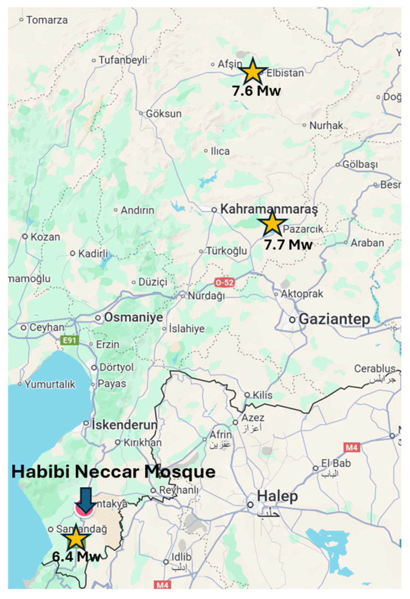
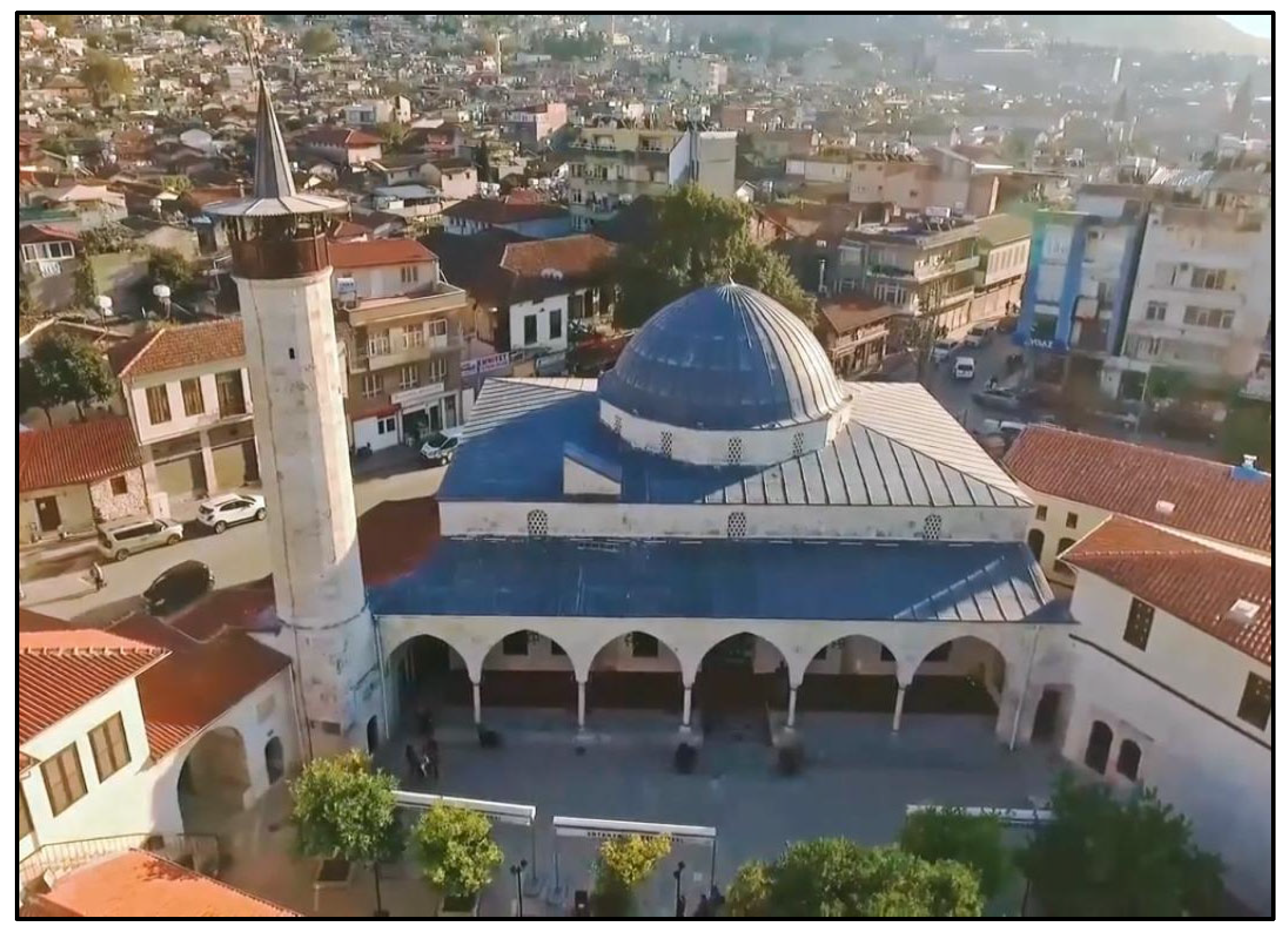
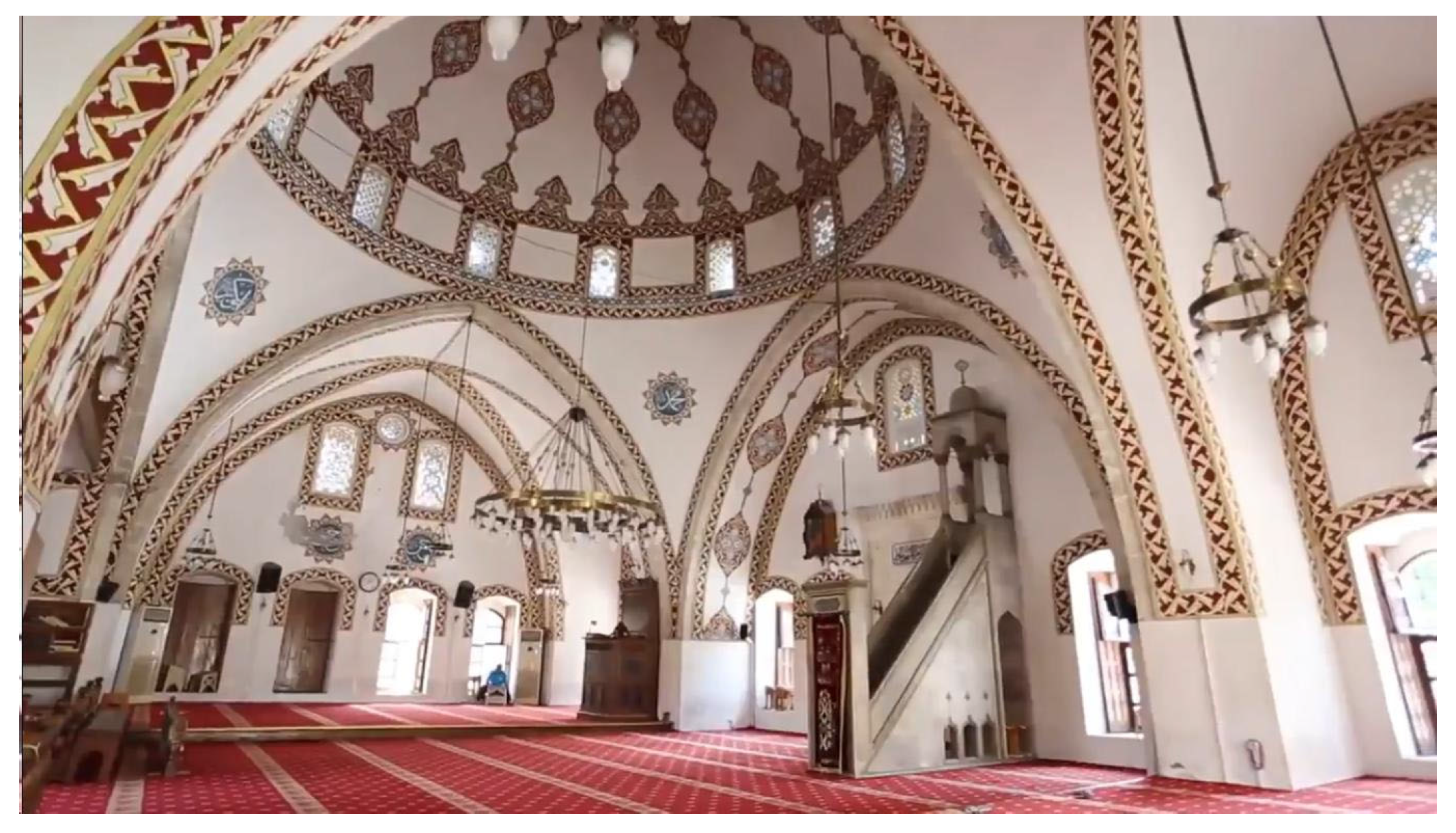
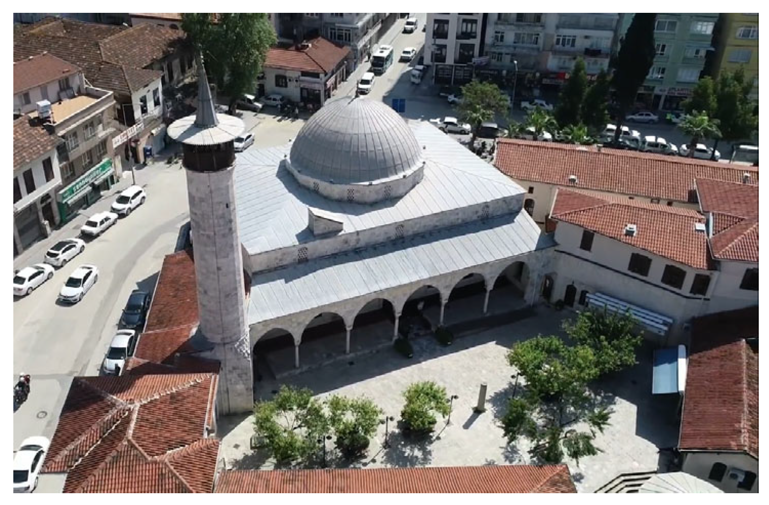
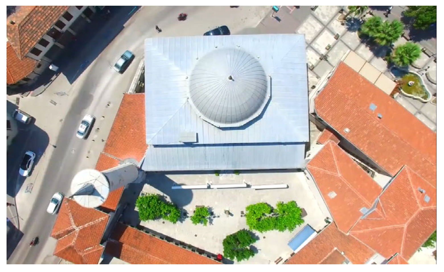
2.1. Case Study: The Mosque and Its History
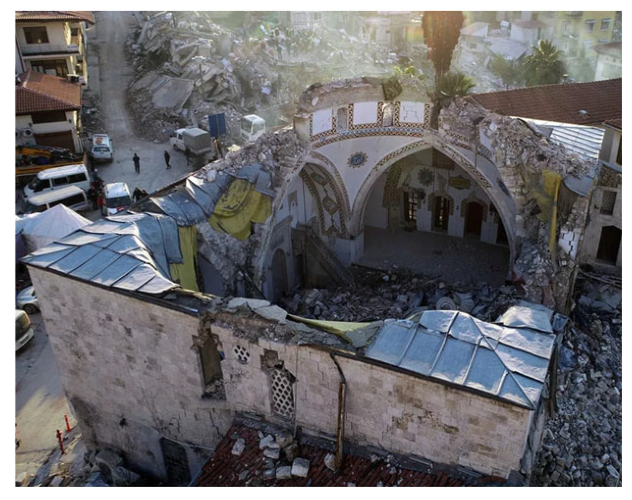
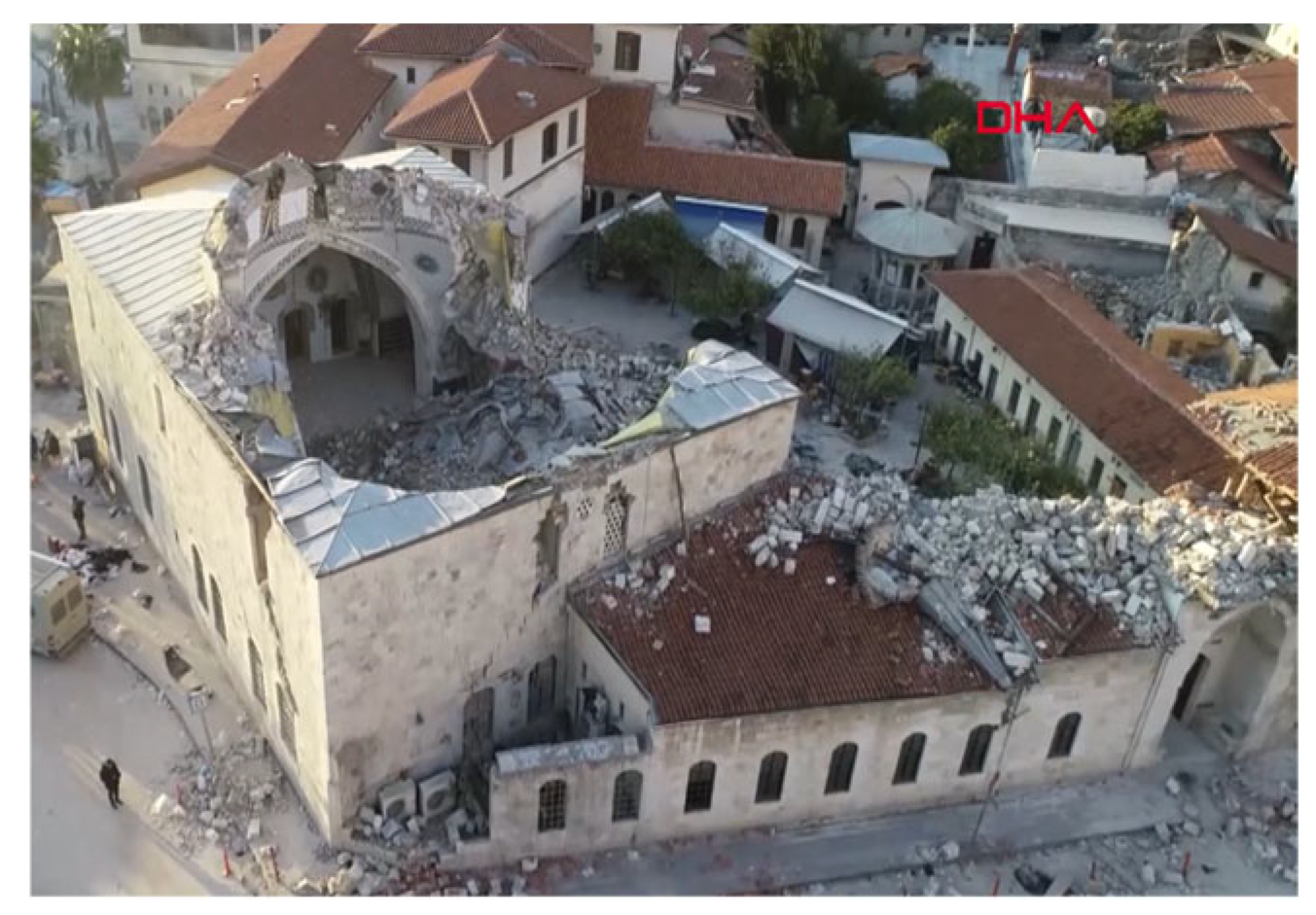
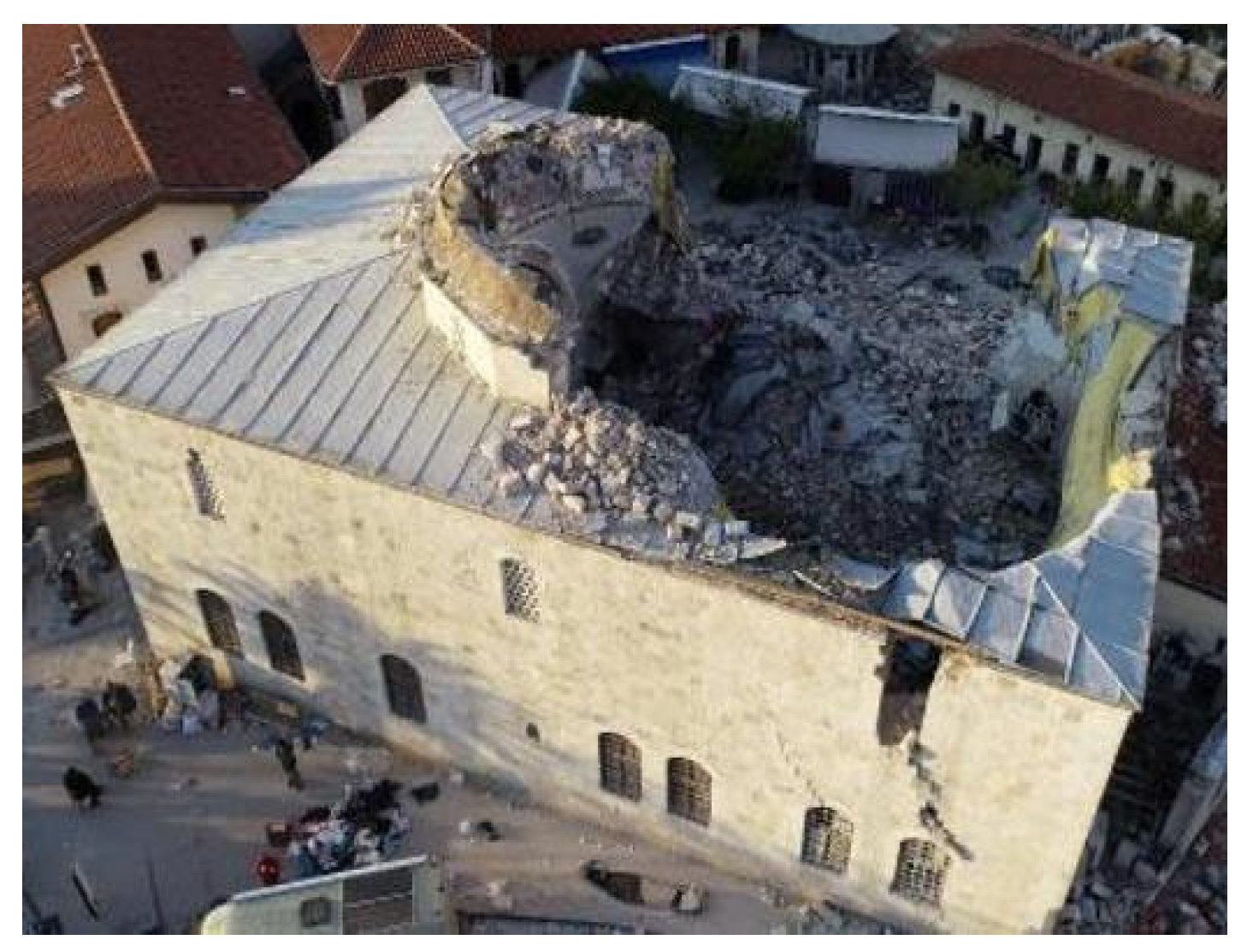
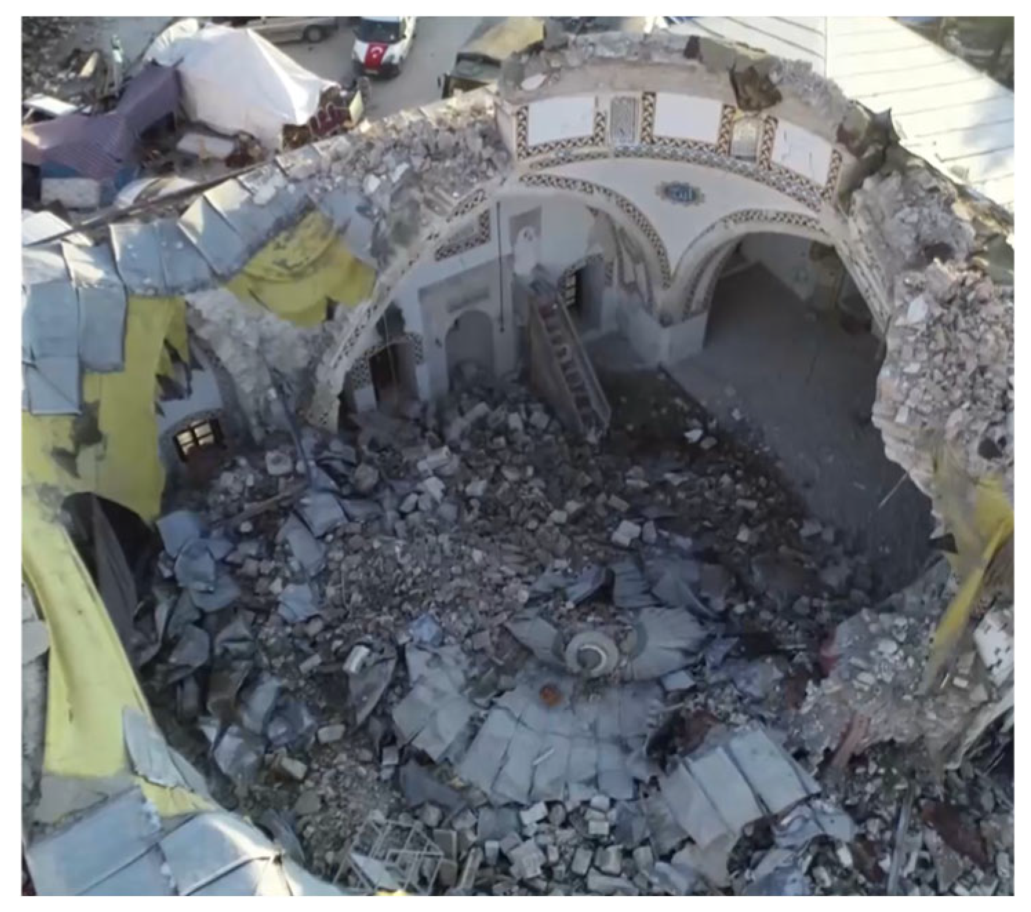
Damage Observations
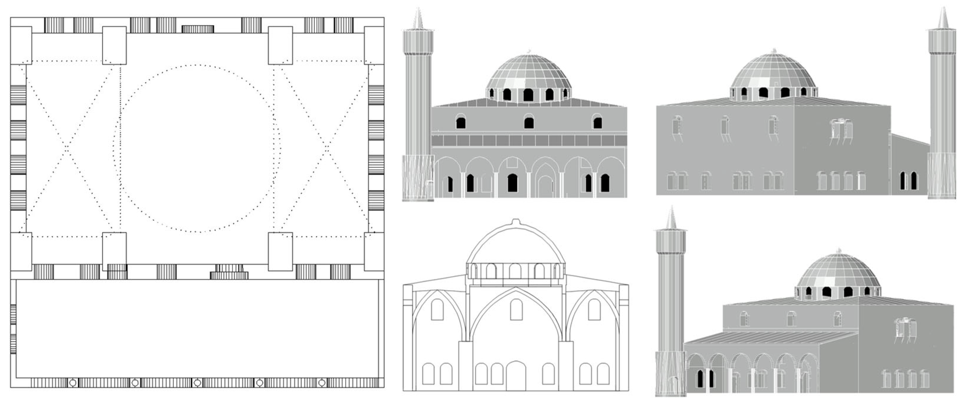
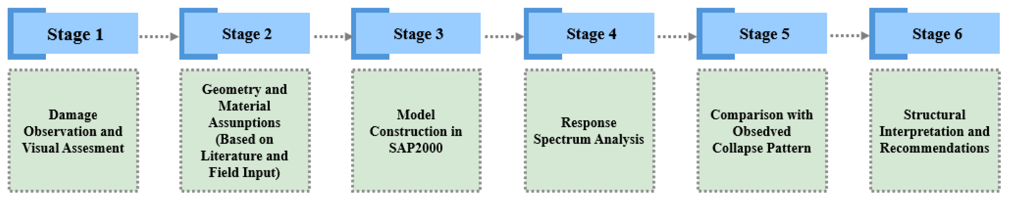
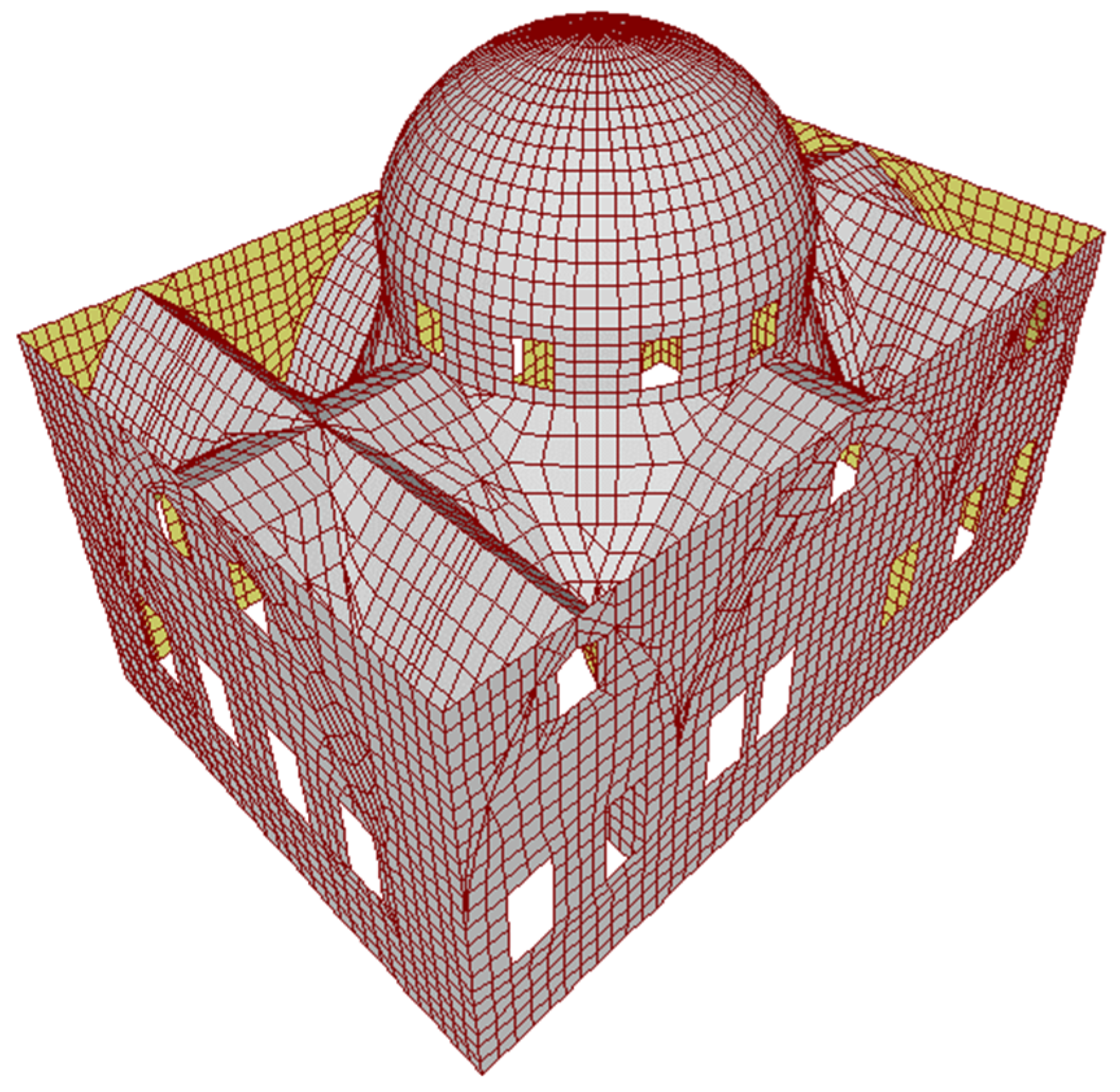
2.2. Methodology: Structural Assessment of the Damaged Building and the Formation of the Numerical Model
Seismic Data for Station Selection, Numerical Model and Analysis of Historical Mosque
3. Results and Discussions: Assessment Method Based on Simplified Linear Dynamic Analysis
4. Conclusions
- These findings not only support the accuracy of the simplified analysis but also offer theoretical insights into post-collapse behavior in historic masonry structures.
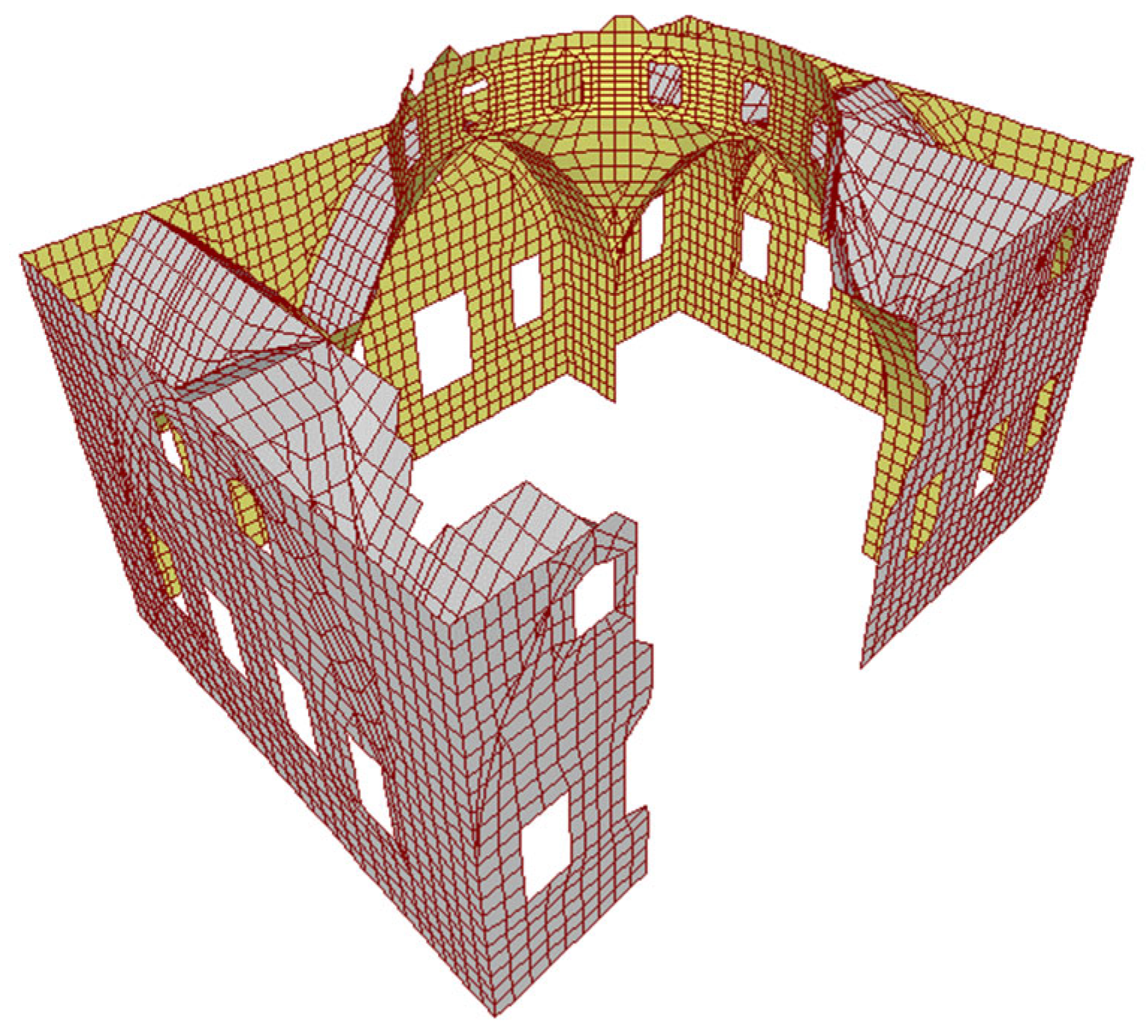
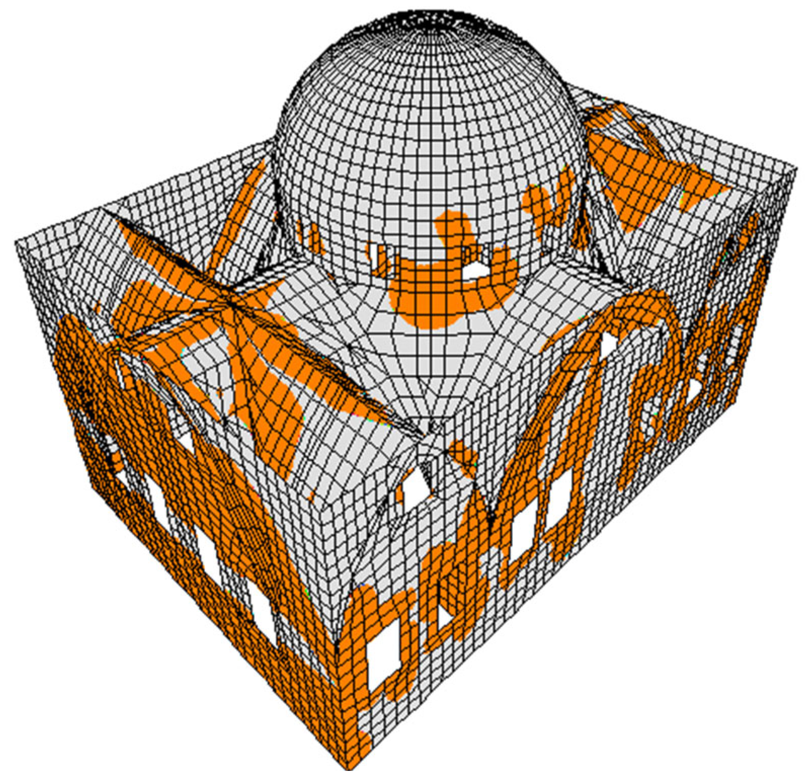
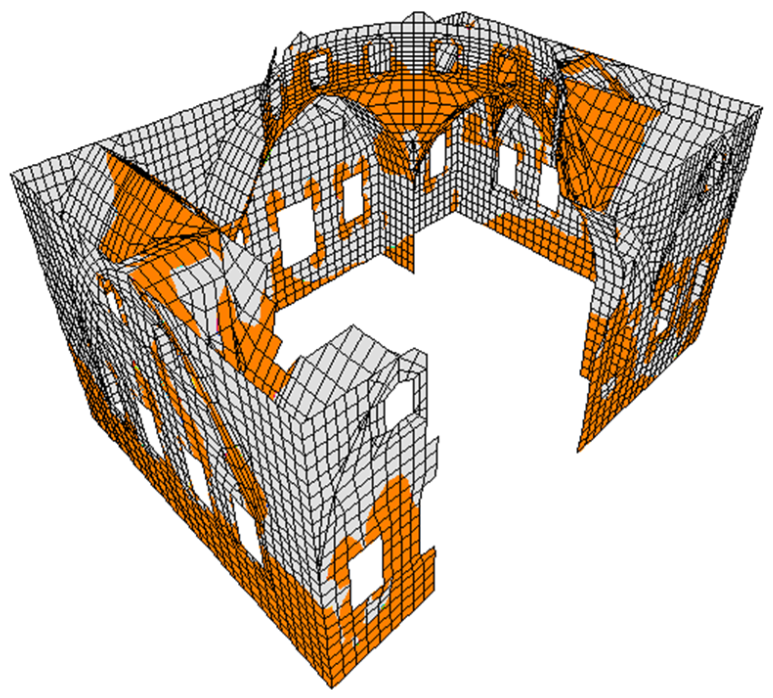
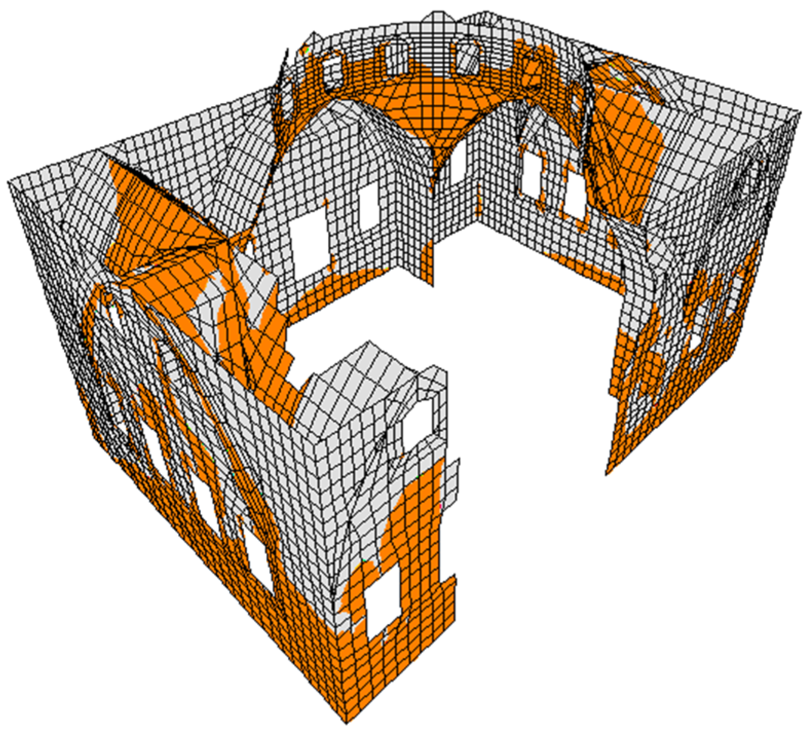
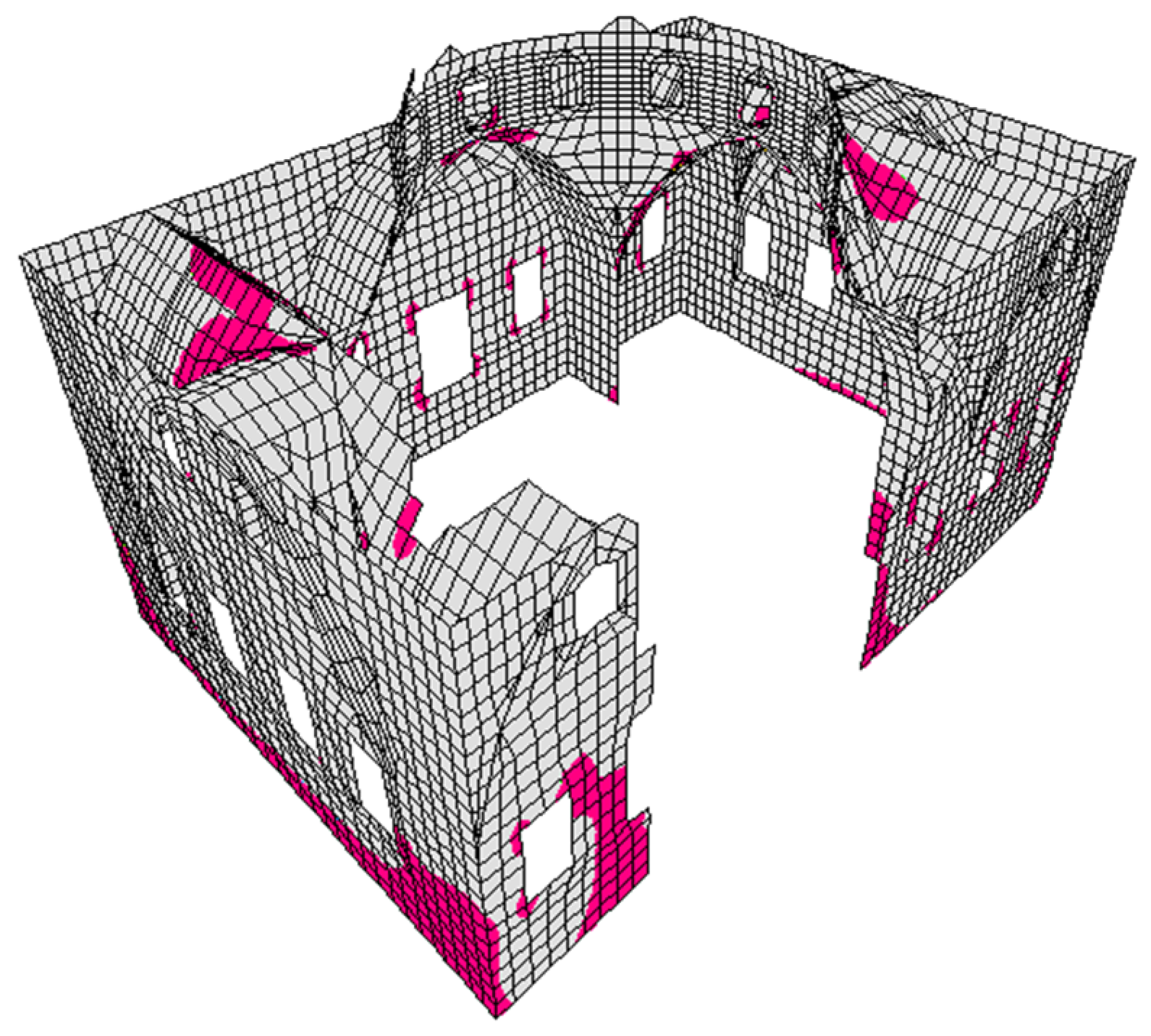
- Stress concentrations at the dome–arch joints and vaults exceeded material limits, contributing to local failures and partial collapse.
- Significant out-of-plane deformations were observed in the remaining walls, making them highly vulnerable to aftershocks and progressive damage.
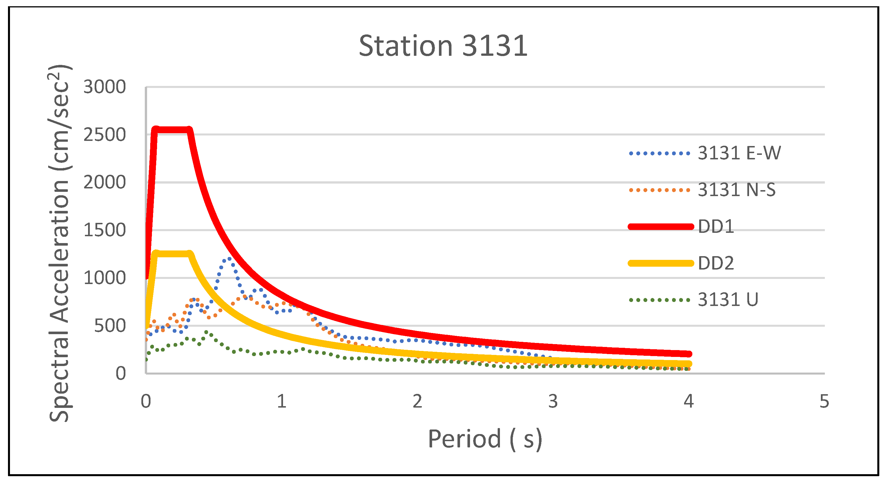
- Ground amplification effects played a major role in increasing the seismic demand, further exacerbating the structural response and damage severity.
- Creating and using nonlinear material modeling in a numerical setting: using detailed nonlinear analyses to show how damage builds up over time and how masonry units and mortar interact with each other.
- Improving damage assessment techniques: utilizing remote sensing, photogrammetry, and AI-based analysis to enhance the rapid evaluation of earthquake-damaged cultural heritage structures.
- Development of standardized emergency assessment protocols: establishing guidelines for the rapid assessment and stabilization of heritage sites in seismic zones.
Funding
Data Availability Statement
Acknowledgments
Conflicts of Interest
References
- Türkiye Cumhuriyeti Cumhurbaşkanlığı Strateji ve Bütçe Başkanlığı. 2023 Kahramanmaraş ve Hatay Depremleri Raporu; Türkiye Cumhuriyeti Cumhurbaşkanlığı Strateji ve Bütçe Başkanlığı: Ankara, Türkiye, 2023. [Google Scholar]
- Kocaman, İ. The effect of the Kahramanmaraş earthquakes (Mw 7.7 and Mw 7.6) on historical masonry mosques and minarets. Eng. Fail. Anal. 2023, 149, 107225. [Google Scholar] [CrossRef]
- Guo, Y.; Li, H.; Liang, P.; Xiong, R.; Hu, C.; Xu, Y. Preliminary report of coseismic surface rupture (part) of Türkiye’s MW7.8 earthquake by remote sensing interpretation. Earthq. Res. Adv. 2024, 4, 100219. [Google Scholar] [CrossRef]
- Available online: https://whc.unesco.org/en/statesparties/tr (accessed on 12 May 2025).
- Baltzopoulos, G.; Baraschino, R.; Chioccarelli, E.; Cito, P.; Vitale, A.; Iervolino, I. Near-source ground motion in the Mw7.8 Gaziantep (Türkiye) earthquake. Earthq. Eng. Struct. Dyn. 2023, 52, 3903–3912. [Google Scholar] [CrossRef]
- Karataş, L.; Ateş, T.; Alptekin, A.; Dal, M.; Yakar, M. A systematic method for post-earthquake damage assessment: Case study of the Antep Castle, Türkiye. Adv. Eng. Sci. 2023, 3, 62–71. [Google Scholar]
- Papazafeiropoulos, G.; Plevris, V. Kahramanmaraş—Gaziantep, Türkiye Mw 7.8 Earthquake on 6 February 2023: Strong ground motion and building response estimations. Buildings 2023, 13, 1194. [Google Scholar] [CrossRef]
- Binici, B.; Yakut, A.; Kadas, K.; Demirel, O.; Akpinar, U.; Canbolat, A.; Yurtseven, F.; Oztaskin, O.; Aktas, S.; Canbay, E. Performance of RC buildings after Kahramanmaraş earthquakes: Lessons toward performance-based design. Earthq. Eng. Eng. Vib. 2023, 22, 883–894. [Google Scholar] [CrossRef]
- Schiavoni, M.; Giordano, E.; Roscini, F.; Clementi, F. Numerical modeling of a majestic masonry structure: A comparison of advanced techniques. Eng. Fail. Anal. 2023, 149, 107293. [Google Scholar] [CrossRef]
- Cosgun, T.; Uzdil, O.; Sayin, B.; Zengin, K.K. Seismic vulnerability assessment of a masonry structure and an FRP-strengthening proposal. Case Stud. Constr. Mater. 2022, 17, e01680. [Google Scholar] [CrossRef]
- Yurdakul, M.; Yılmaz, F.; Artar, M.; Can, Ö.; Öner, E.; Daloğlu, A.T. Investigation of time-history response of a historical masonry minaret under seismic loads. Structures 2021, 30, 265–276. [Google Scholar] [CrossRef]
- Kocaman, İ. Effect of restoration interventions on the seismic behavior of historical masonry buildings: The case of Molla Siyah mosque. Eng. Fail. Anal. 2023, 148, 107206. [Google Scholar] [CrossRef]
- Kaya, M.; Özkan, T. Seismic vulnerability of historical masonry structures: The case of Turkey. Quat. Int. 2021, 606, 120–131. [Google Scholar] [CrossRef]
- Aydın, K.; Yılmaz, H. Failure analysis of masonry structures under seismic loads: A review of recent developments. Eng. Fail. Anal. 2022, 131, 106706. [Google Scholar] [CrossRef]
- Toker, B.; Alkan, R. Earthquake response of historical buildings: Case studies from the Middle East. J. Earthq. Eng. 2019, 23, 456–478. [Google Scholar] [CrossRef]
- Kılıç Demircan, R. Determination of earthquake resistance of historical masonry inn with finite element analysis. Bull. Earthq. Eng. 2025, 23, 32693293. [Google Scholar] [CrossRef]
- D’amato, M.; Michelangelo, L.; Daniela, D.F. Simplified Seismic Analyses of Ancient Churches in Matera’s Landscape. Int. J. Archit. Herit. 2018, 12, 369–382. [Google Scholar] [CrossRef]
- Valente, M. Earthquake response and damage patterns assessment of two historical masonry churches with bell tower. Eng. Fail. Anal. 2023, 151, 107418. [Google Scholar] [CrossRef]
- Valente, M. Seismic behavior and damage assessment of two historical fortified masonry palaces with corner towers. Eng. Fail. Anal. 2022, 134, 106003. [Google Scholar] [CrossRef]
- Valente, M. Seismic vulnerability assessment and earthquake response of slender historical masonry bell towers in South-East Lombardia. Eng. Fail. Anal. 2021, 129, 105656. [Google Scholar] [CrossRef]
- Sood, R.; Salgado, R. Investigation of geosynthetic-reinforced soil performance under different conditions. Open Constr. Build. Technol. J. 2021, 15, 135–148. [Google Scholar] [CrossRef]
- Kumar, R.; Ahmad, S. Seismic risk assessment of multi-story buildings using nonlinear static procedures. J. Build. Perform. 2018, 13, 189–204. [Google Scholar]
- Lee, H.; Choi, J.; Kim, H. Performance assessment of seismic retrofitting techniques for structures subjected to aftershocks. Arch. Civ. Mech. Eng. 2021, 21, 312–328. [Google Scholar] [CrossRef]
- Gonen, S.; Soyoz, S. Investigations on the elasticity modulus of stone masonry. Structures 2021, 30, 378–389. [Google Scholar] [CrossRef]
- Asteris, P.G.; Chronopoulos, M.; Chrysostomou, C.; Varum, H.; Plevris, V.; Kyriakides, N.; Silva, V. Seismic vulnerability assessment of historical masonry structural systems. Eng. Struct. 2014, 62–63, 118–134. [Google Scholar] [CrossRef]
- Mainstone, R.J. Structural Analysis, Structural Insights, and Historical Interpretation. J. Soc. Archit. Hist. 1997, 56, 316–340. [Google Scholar] [CrossRef]
- Saleme Gidrão, G.M.; Carrazedo, R.; Bosse, R.M.; Silvestro, L.; Ribeiro, R.; de Souza, C.F.P. Numerical Modeling of the Dynamic Elastic Modulus of Concrete. Materials 2023, 16, 3955. [Google Scholar] [CrossRef]
- Mallardo, V.; Malvezzi, R.; Milani, E.; Milani, G. Seismic vulnerability of historical masonry buildings: A case study in Ferrara. Eng. Struct. 2008, 30, 2223–2241. [Google Scholar] [CrossRef]
- Romera, L.E.; Hernández, S.; Reinosa, J.M. Numerical characterization of the structural behaviour of the Basilica of Pilar in Zaragoza (Spain). Part 1: Global and local models. Adv. Eng. Softw. 2008, 39, 301–314. [Google Scholar] [CrossRef]
- Mele, E.; De Luca, A.; Giordano, A. Modelling and analysis of a basilica under earthquake loading. J. Cult. Herit. 2003, 4, 355–367. [Google Scholar] [CrossRef]
- Peña, F.; Lourenço, P.B.; Mendes, N.; Oliveira, D.V. Numerical models for the seismic assessment of an old masonry tower. Eng. Struct. 2010, 32, 1466–1478. [Google Scholar] [CrossRef]
- Betti, M.; Vignoli, A. Modelling and analysis of a Romanesque church under earthquake loading: Assessment of seismic resistance. Eng. Struct. 2008, 30, 352–367. [Google Scholar] [CrossRef]
- Betti, M.; Vignoli, A. Assessment of seismic resistance of a basilica-type church under earthquake loading: Modelling and analysis. Adv. Eng. Softw. 2008, 39, 258–283. [Google Scholar] [CrossRef]
- Betti, M.; Galano, L.; Vignoli, A. Finite element modelling for seismic assessment of historic buildings. In Earthquakes and Their Impact on Society; Springer: Cham, Switzerland, 2016; pp. 1–14. [Google Scholar] [CrossRef]
- Adami, C.E.; Vintzileou, E. Interventions to historic masonries: Investigation of the bond mechanism between stones or bricks and grouts. Mater. Struct. Constr. 2008, 41, 255–267. [Google Scholar] [CrossRef]
- İstek, E. Seyyahlarin gözüyle antakya şehri (10–19. yüzyillar arasi). Pamukkale Univ. J. Soc. Sci. Inst. 2020, 227–246. [Google Scholar] [CrossRef]
- Diker, M.; Çeker, N. Religious Building for the City Identity: The Case of Antioch. J. Plan. 2017, 27, 180–192. [Google Scholar] [CrossRef]
- Pınar, M. Antakya’da Restore Edilen ve Edilecek Yapılar Üzerinde Çevrenin Etkisi. Turk. Stud. 2015, 11, 579–604. [Google Scholar]
- Eykay, İ.; Dalgın, T.; Çeken, H. The Evaluation of Religious Tourism Potential in Antakya. J. Life Econ. 2015, 2, 59–74. [Google Scholar] [CrossRef]
- Habibi Neccar Camisi. Available online: https://www.kulturportali.gov.tr/turkiye/hatay/gezilecekyer/habib-i-neccar-camii (accessed on 2 January 2025).
- Sarhosis, V.; Giarlelis, C.; Karakostas, C.; Smyrou, E.; Bal, I.E.; Valkaniotis, S.; Ganas, A. Observations from the March 2021 Thessaly Earthquakes: An earthquake engineering perspective for masonry structures. Bull. Earthq. Eng. 2022, 20, 5483–5515. [Google Scholar] [CrossRef]
- Anadolu’nun İlk Camisi. Available online: http://www.hatay.gov.tr/anadolunun-ilk-camisi (accessed on 2 January 2025).
- Habib-i Neccar. Available online: https://www.dha.com.tr/video/antakyadaki-14-asirlik-habib-i-neccar-camisi-depremde-yikildi-video-2204262 (accessed on 2 January 2025).
- Antakya Depremi. Available online: https://www.istockphoto.com/tr/foto%C4%9Fraf/kahramanmaras-earthquake-gm1474099767-504056395 (accessed on 22 May 2025).
- Cabalar, A.; Canbolat, A.; Akbulut, N.; Tercan, S.; Isik, H. Soil liquefaction potential in Kahramanmaras, Turkey. Geomat. Nat. Hazards Risk 2019, 10, 1822–1838. [Google Scholar] [CrossRef]
- Lungu, D.; Arion, C. Seismic Risk and/or Real Estate Risk for the Bucharest Heritage Buildings. In Proceedings of the 15th World Conference on Earthquake Engineering (WCEE), Lisbon, Portugal, 24–28 September 2012; pp. 1–10. [Google Scholar]
- Modena, C.; Valluzzi, M.R.; Da Porto, F.; Casarin, F. Structural aspects of the conservation of historic masonry constructions in seismic areas: Remedial measures and emergency actions. Int. J. Archit. Herit. 2011, 5, 539–558. [Google Scholar] [CrossRef]
- Penna, A.; Morandi, P.; Rota, M.; Manzini, C.F.; da Porto, F.; Magenes, G. Performance of masonry buildings during the Emilia 2012 earthquake. Bull. Earthq. Eng. 2014, 12, 2255–2273. [Google Scholar] [CrossRef]
- Bozyiğit, B.; Özdemir, A.; Donmez, K.; Dalgic, K.D.; Durgut, E.; Yesilyurt, C.; Dizgin, Y.; Yıldeniz, C.; Ispir, M.; Bedirhanoglu, I.; et al. Damage to monumental masonry buildings in Hatay and Osmaniye following the 2023 Turkey earthquake sequence: The role of wall geometry, construction quality, and material properties. Earthq. Spectra 2024, 40, 1870–1904. [Google Scholar] [CrossRef]
- Baker, J.W. Measuring bias in structural response caused by ground motion scaling. In Proceedings of the 8th Pacific Conference on Earthquake Engineering, Singapore, 5–7 December 2007; p. 56. [Google Scholar]
- Lourenço, P.B. Computations on historic masonry structures. Prog. Struct. Eng. Mater. 2002, 4, 301–319. [Google Scholar] [CrossRef]
- Lourenço, P.B.; Mendes, N.; Ramos, L.F.; Oliveira, D.V. Analysis of Masonry Structures Without Box Behavior. Int. J. Archit. Herit. 2011, 5, 369–382. [Google Scholar] [CrossRef]
- Turkey Building Earthquake Code (TBEC-2018). Available online: https://www.resmigazete.gov.tr/eskiler/2018/03/20180318M1-2.htm (accessed on 22 May 2025).


| Element Type | Modulus of Elasticity E (kN/m2) | Unit Weight (kN/m3) |
|---|---|---|
| Brick dome and the pendantives (with mortar) | 1,200,000 (1200 MPa) | 24 |
| Stone walls (with mortar) | 450,000 (450 MPa) | 24 |
| Pillars (with inner filled materials) | 200,000 (200 MPa) | 34 |
| Station No. | Location | PGA %g |
|---|---|---|
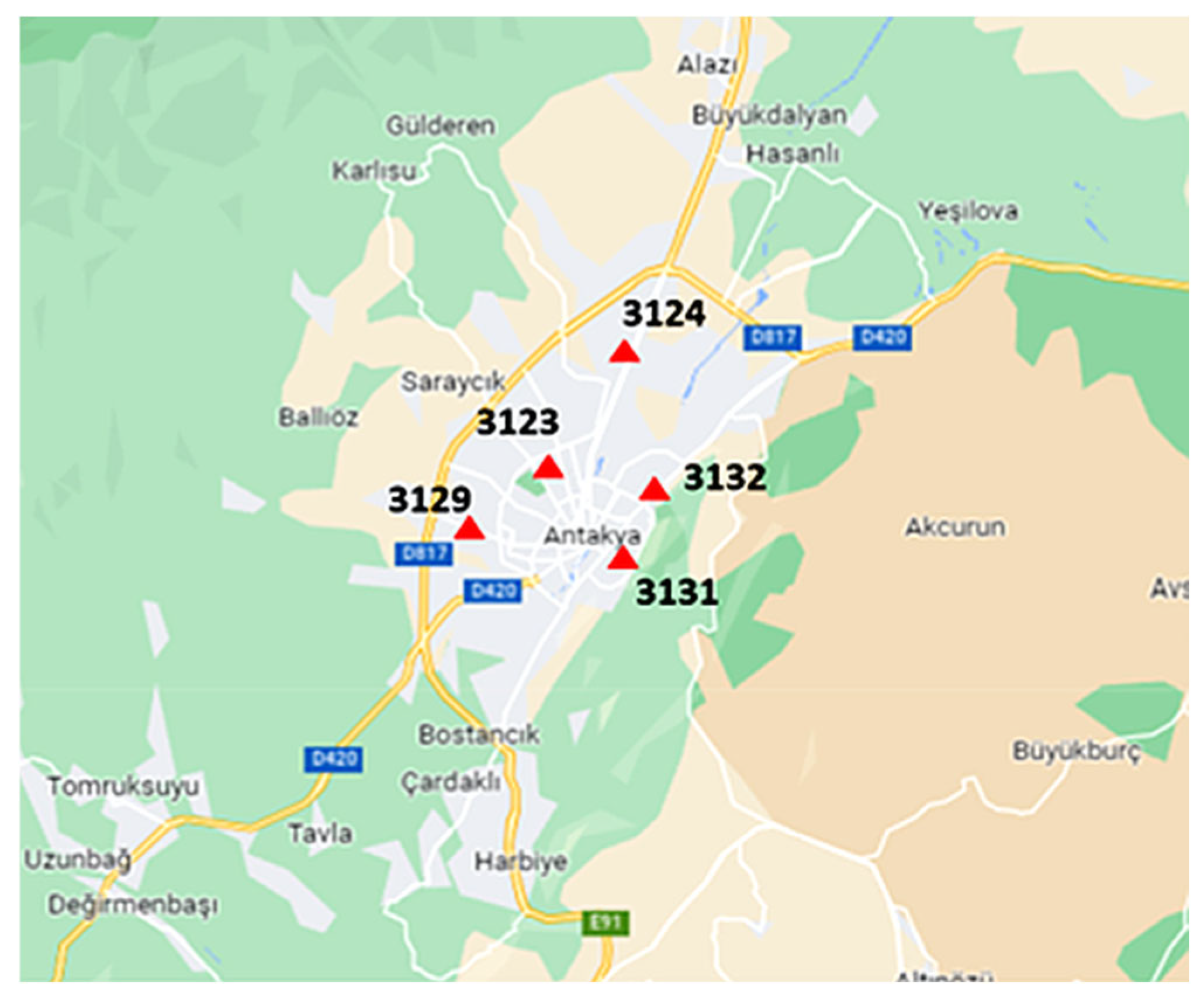
| 3123 | 36.214° N 36.160° E | 66.73 |
| 3124 | 36.239° N 36.172° E | 65.04 |
| 3129 | 36.191° N 36.134° E | 137.86 |
| 3131 | 36.191° N 36.163° E | 37.19 |
| 3132 | 36.207° N 36.172° E | 52.51 |
| Mode Number | Period (s) | ΣMeff % in X- Longitudinal Direction | ΣMeff % in Y- Transversal Direction |
|---|---|---|---|
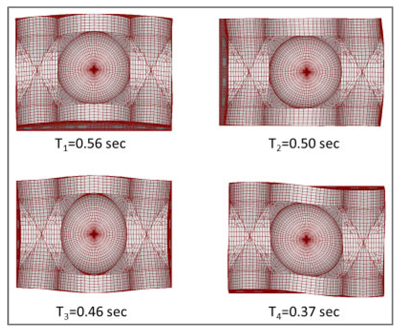
| 1 | 0.56 | 0 | 75.05 |
| 2 | 0.50 | 78.05 | 75.05 |
| 3 | 0.46 | 78.05 | 75.05 |
| 4 | 0.36 | 78.07 | 75.06 |
| 22 | 0.16 | 84.12 | 83.13 |
| 23 | 0.15 | 84.14 | 83.13 |
| 24 | 0.15 | 84.38 | 83.13 |
| 25 | 0.14 | 84.38 | 83.20 |
| Mode Number | Period (s) | ΣMeff % in X- Longitudinal Direction | ΣMeff % in Y- Transversal Direction |
|---|---|---|---|
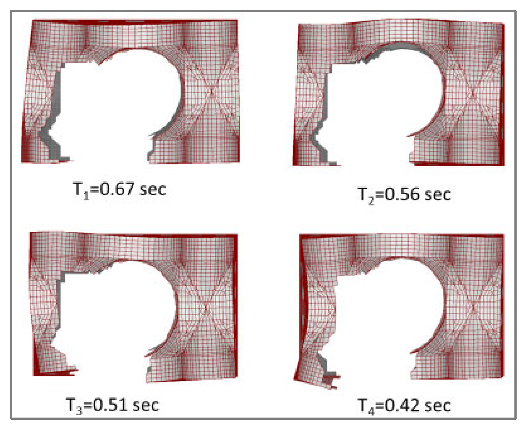
| 1 | 0.67 | 6.25 | 15.89 |
| 2 | 0.56 | 44.92 | 32.05 |
| 3 | 0.51 | 68.97 | 37.59 |
| 4 | 0.42 | 69.36 | 69.79 |
| 27 | 0.13 | 83.16 | 83.83 |
| 28 | 0.13 | 83.25 | 84.01 |
| 29 | 0.13 | 83.31 | 84.04 |
| 30 | 0.12 | 83.38 | 84.18 |
Disclaimer/Publisher’s Note: The statements, opinions and data contained in all publications are solely those of the individual author(s) and contributor(s) and not of MDPI and/or the editor(s). MDPI and/or the editor(s) disclaim responsibility for any injury to people or property resulting from any ideas, methods, instructions or products referred to in the content. |
© 2025 by the author. Licensee MDPI, Basel, Switzerland. This article is an open access article distributed under the terms and conditions of the Creative Commons Attribution (CC BY) license (https://creativecommons.org/licenses/by/4.0/).
Share and Cite
Kılıç Demircan, R. Simplified FE-Based Post-Earthquake Vulnerability Assessment of a Partially Collapsed Historic Mosque. Buildings 2025, 15, 1849. https://doi.org/10.3390/buildings15111849
Kılıç Demircan R. Simplified FE-Based Post-Earthquake Vulnerability Assessment of a Partially Collapsed Historic Mosque. Buildings. 2025; 15(11):1849. https://doi.org/10.3390/buildings15111849
Chicago/Turabian StyleKılıç Demircan, Rüya. 2025. "Simplified FE-Based Post-Earthquake Vulnerability Assessment of a Partially Collapsed Historic Mosque" Buildings 15, no. 11: 1849. https://doi.org/10.3390/buildings15111849
APA StyleKılıç Demircan, R. (2025). Simplified FE-Based Post-Earthquake Vulnerability Assessment of a Partially Collapsed Historic Mosque. Buildings, 15(11), 1849. https://doi.org/10.3390/buildings15111849