Article

Study on the Effect of Crack Density and Micro-Cracking Block Size of In Situ Softening Semi-Rigid Base

by
Liting Yu
1,2,*,
Chunyang Yu
1,2,
Haiqi He
3,
Zikai Xu
3,
Donliang Hu
3,
Rui Li
3 and
Jianzhong Pei
3
1
School of Traffic and Transportation Engineering, Xinjiang University, Boda Campus of Xinjiang University No. 777 Huarui Road, Shuimogou District, Urumqi 830017, China
2
Xinjiang Key Laboratory of Green Construction and Smart Traffic Control of Transportation Infrastructure, Xinjiang University, Boda Campus of Xinjiang University No. 777 Huarui Road, Shuimogou District, Urumqi 830017, China
3
School of Highway, Chang’an University, Middle Section of South Erhuan Road, Xi’an 710064, China
*
Author to whom correspondence should be addressed.
Buildings 2025, 15(11), 1791; https://doi.org/10.3390/buildings15111791
Submission received: 15 April 2025 / Revised: 9 May 2025 / Accepted: 19 May 2025 / Published: 23 May 2025
(This article belongs to the Special Issue Carbon-Neutral Infrastructure: 2nd Edition)

Abstract

:
Reflection cracking in semi-rigid bases is a widespread distress that undermines highway safety. Priority should be given to this issue to ensure the normal performance of large-scale semi-rigid base asphalt pavements that have reached the end of their service life. At present, scholars have deeply studied and applied the theory of pavement surface layer fracture damage. However, the study of semi-rigid bases only focuses on pavement temperature influence, crack prediction, and reflection crack retardation, and there is a lack of further research on crack-related characteristics. Building on the novel concept of in situ softening for semi-rigid bases, we employ finite element analysis to quantify how transverse crack density affects overall stiffness and derive targeted softening strategies accordingly. By establishing the base micro-cracking treatment cracking block-size influence model, this study analyzes the load-bearing characteristics of cracking blocks of different sizes and recommends optimal block dimensions. This study provides practical guidance for the treatment of semi-rigid bases with maximum efficiency by expanding the application of fracture mechanics at the microscale and providing practical guidance for the high-value rehabilitation of semi-rigid bases.

1. Introduction

Highway maintenance almost always targets the surface layer, leaving the underlying semi-rigid base, and it is difficult and costly to reconstruct and extend its service past its design life. Although this base initially provides excellent strength and stability, its fatigue resistance and load-bearing capacity decline as micro-cracks develop, posing an insidious risk to long-term pavement performance [1]. Base cracks are extremely insidious and costly to detect and treat. They usually need to be excavated and rebuilt once damaged, and the old base material cannot be effectively utilized. Therefore, it is of great guiding significance to accurately predict the disease state of semi-rigid bases in extended service and deal with them on demand, which will prolong the service life of highways and convert the old pavement materials with high value.
The crack theory of semi-rigid base pavements is guided by the development of basic mechanics. In recent years, the frontier of related mechanics research has mainly focused on fracture mechanics and damage mechanics, which are widely used in various fields, such as materials research and engineering structure design. Botvina [2] analyzed the process of damage accumulation and crack growth under static and cyclic loading, as well as the change in physical properties related to the increase in material damage, and confirmed that when damage reaches a critical condition, stage transformation occurs, and a macroscopic large crack is formed by crack penetration. Maurizi et al. [3] studied the influence of three-dimensional effects on the brittle fracture behavior of linear, elastic, homogeneous, and isotropic solids with cracks or notches under the assumption of small-scale plasticity. Shahbazpanahi et al. [4] studied the fracture mechanics theory of the crack propagation of reinforced deep beams and found that the propagation route followed the assumption of linear and nonlinear conditions. Clayton [5] presents examples of fracture and phase transition boundaries to demonstrate a method of obtaining physical predictive models from Finsler-type continuum field theories. Barras et al. [6] have shown that there is a frictional fracture relationship, and when the crack-like condition is met, the frictional fracture dynamics are approximately described by the energy balance equation of crack-like fracture mechanics. Paglialunga et al. [7] studied fault weakening during frictional fractures by obtaining the near-fault stress-slip curve from the strain matrix. Doitrand et al. [8] formally proposed a coupling criterion in the framework of finite fracture mechanics using experimental device obstacles to prevent cracks from advancing. To take into account the nonlinear behavior of the material, Gvirtzman et al. [9] created a finite element model of a two-dimensional disk test, and the study showed that there was a slow nucleation boundary before fracture, but it still cannot be described by fracture mechanics. Pabitra et al. [10] established a pavement temperature shrinkage cracking model under Coulomb friction between the surface course and the base course, derived the temperature stress expression of the sinusoidal temperature field change, and proposed a crack spacing calculation formula. Mohammad [11] established a road surface temperature prediction model based on meteorological data, determined the shrinkage coefficient of an asphalt mixture at different temperatures, and used the program to predict the surface-cracking time. Jin-Whoy et al. [12], based on pavement measurement results, found a relationship between crack closure and zero-stress temperature (ZST). Aidin J et al. [13] observed and studied the influence of surface cracks on the thermal curve of a concrete infrastructure under different weather conditions. Pengyu Xie et al. [14] analyzed the possibility of reflection cracks caused by long-term cyclic traffic load under the thermal cycle of composite pavements. Hui Zhang et al. [15] observed the relevant mechanism of reflection cracks on snow-melting and anti-icing pavements. Quentin F Félix Adam et al. [16] studied heating systems to mitigate low-temperature crack development.
In the past, the research methods for pavement fracture damage were mainly macroscopic tests (indoor specimens [17,18] and full-scale outdoor tests [19,20]). With the progress of computer technology and the continuous development and improvement of basic disciplines, the theoretical research on the fracture damage of pavements and semi-rigid bases is developing rapidly based on fracture mechanics and damage mechanics, combined with numerical calculation methods such as finite element method simulation [21]. Based on the extended finite element numerical operation method, Golewski et al. [22] analyzed the correlation of cracks contained in silica-fly ash-plain concrete structures and mainly studied the development law of type II cracks. Gracie et al. [23,24] proposed a supplementary equation based on a patch block created on the concept of a discontinuous Galerkin equation. This method can use the corresponding mesh size and effective connection at the junction of the crack enrichment and non-enrichment areas when meshing the finite element modeling, which can make the simulation results more accurate. In the field of engineering applications, Dave et al. [25] conducted in-depth research on a cohesive zone model in fracture mechanics and applied this model to the analysis and demonstration of actual pavement cracks. Their conclusion shows that the numerical calculation using the cohesive zone model in fracture mechanics is closer to the actual engineering behavior. A study by David et al. [26] was oriented toward geosynthetics for delaying and preventing the generation of reflective cracks in pavements. The study simulated the dynamic effects of cracking with actual vehicle loading forces and concluded that geogrids made of geosynthetics are effective and that the prevention effect increases with material strength.
In summary, the current research on pavement cracking mainly focuses on the influence of a single index at the tip of a crack, which is less related to the actual pavement structure. Due to the large difference in the ratio of crack and pavement footage size and the existence of technical barriers, there is a relative lack of research models on the overall impact of cracks on pavements and the three-dimensional loading effect of crack-containing pavements. In the past, the finite element model of crack propagation was mainly based on two-dimensional modeling and the microscopic study of a single crack, and the research direction of fracture mechanics includes the conditions of crack generation and propagation in materials or structures. After a crack occurs in a pavement, its nature will not be accurate enough if it is determined completely by mechanical behavior under the assumption of continuity. The macroscopic influence of crack distribution on pavements and the evaluation method of pavement damage caused by vehicles need to be further improved and studied.
To better ensure the functional status of the service of pavements and obtain more comprehensive and accurate information about the internal cracks of semi-rigid bases, this paper innovatively puts forward the concept of the in situ softening utilization of a semi-rigid base. Through the establishment of the pavement, the semi-rigid base crack density, and the semi-rigid base cracking block-size influence model, this study proposes semi-rigid base softening timings and cracking block-size recommendations, which enhance the use of semi-rigid base residual load-bearing capacity space, expand the research path of pavement fracture mechanics’ fine development, and provide a reference for the evaluation of the pavement performance after ultra-long service and maintenance and repair.

2. Exploitation Concept for In Situ Softening of Semi-Rigid Base

2.1. Mechanical Properties of the Semi-Rigid Base During the Service Period

A semi-rigid base is a kind of inorganic binder stabilized base, which is characterized by a dense structure, small voids, low permeability, and good water stability. The common types are lime-stabilized soil, cement-stabilized soil, and lime industrial waste-stabilized soil. From macro analysis, a base composed of these materials has good integrity. Under traffic load and fatigue, the main reason for the damage of a structure in the service state is that the material cracks penetrate and cause the board to break, failing the base structure.
The stress–strain relationship is the manifestation of the deformation and destruction of materials under external loading. Since the service and micro-cracking processes of semi-rigid base materials are dominated by compressive stresses, they are mainly presented in the form of longitudinal cracks. Under uniaxial compressive stress, this study analyzed the mechanical performance of crack initiation, stable crack expansion, and crack destabilization. According to the three stages of material failure caused by crack propagation, the mechanical behavior of semi-rigid base material cracking failure corresponds to three stages—the quasi-elastic stage, the stable growth stage, and the critical stress stage (the unstable growth stage)—as shown in Figure 1.
In the quasi-elastic stage, the stress–strain curve is a straight line. Within 30% of the ultimate compressive strength, the micro-cracks are in a stable state due to the initial material. In this state, the micro-cracks do not tend to develop into the initial cracks, but the stress concentration at the tip of the micro-cracks leads to local micro-cracks, which alleviate the stress concentration and keep the structure in a balanced and stable state. A micro-crack is an unrecoverable micro-deformation, but the deformation is very small, and it is difficult to reflect macroscopically. The stress–strain test curve shows that the stress–strain curve is not a straight line under a low-stress state but a concave shape near the origin. In the stable growth stage, the stress–strain curve gradually deviates from a straight line, the curvature becomes larger and larger, and the external force increases, resulting in the continuous generation of micro-cracks. Under the action of shear–compression-combined stress, the micro-cracks at the joint surface of different raw materials develop slowly and steadily, forming a wide and continuous crack network, and the unrecoverable deformation increases significantly. In the critical stress stage (the unstable growth stage), the stress–strain curve is curved. When the stress level is maintained at 70~90% of the ultimate compressive strength, the existing cracks enter the unstable growth stage, the whole structure becomes unstable, and the rapid expansion of cracks leads to structural damage. In practical situations, the cracking behavior of the base layer often falls within the transitional regime between the size effects of strength theory and those of linear elastic fracture mechanics, as illustrated in Figure 2.
Based on the requirements of structural reliability design and the mechanical behavior of base structure cracking, the corresponding maintenance modes of the semi-rigid base in the quasi-elastic stage, stable growth stage, and critical stress stage (unstable growth stage) under vehicle load should belong to asphalt surface milling and resurfacing, base reinforcement after surface milling, and reconstruction of the base and pavement structure, respectively. The semi-rigid base micro-cracking treatment method is in the stage of stable growth of base cracking.

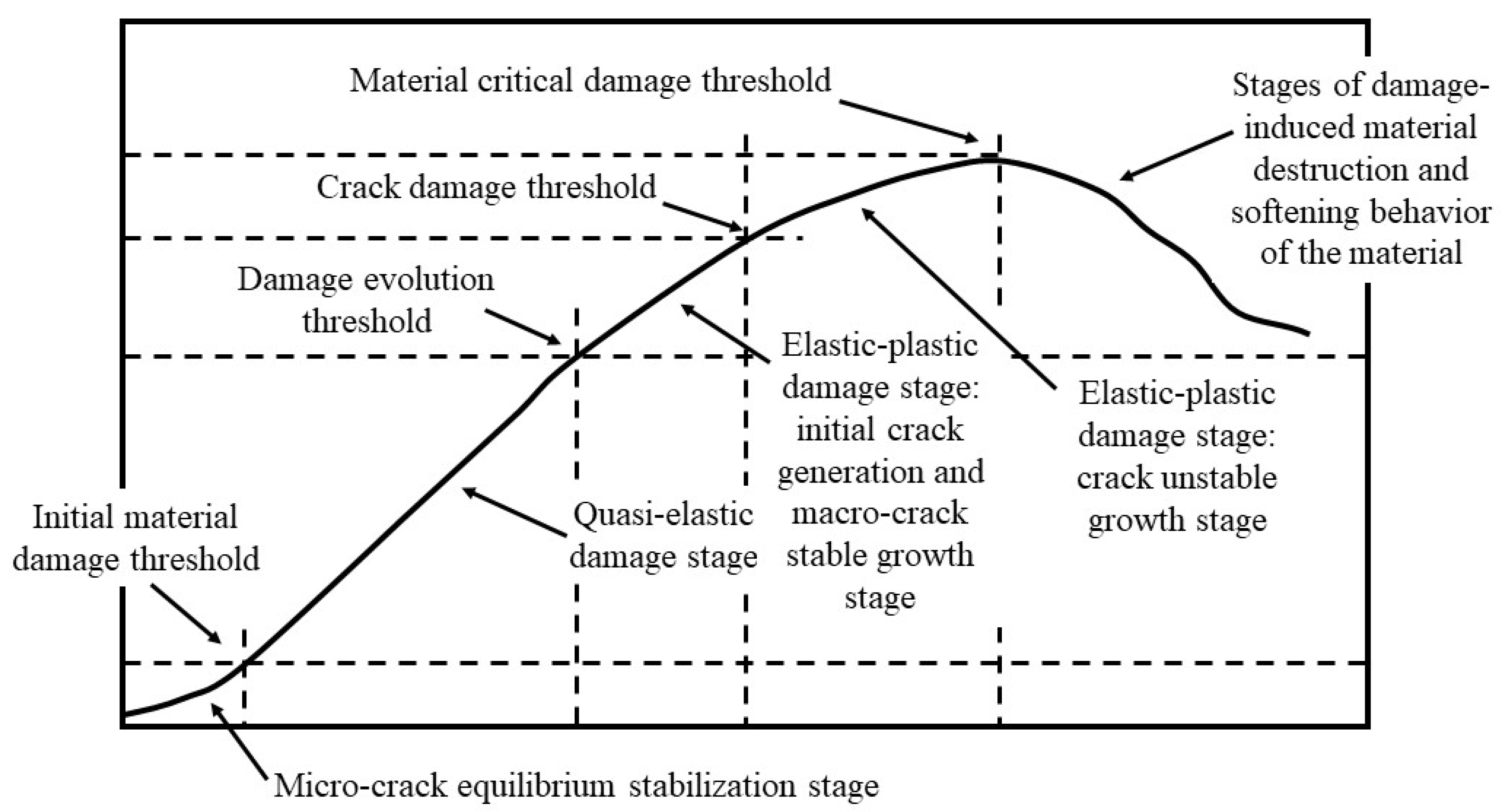
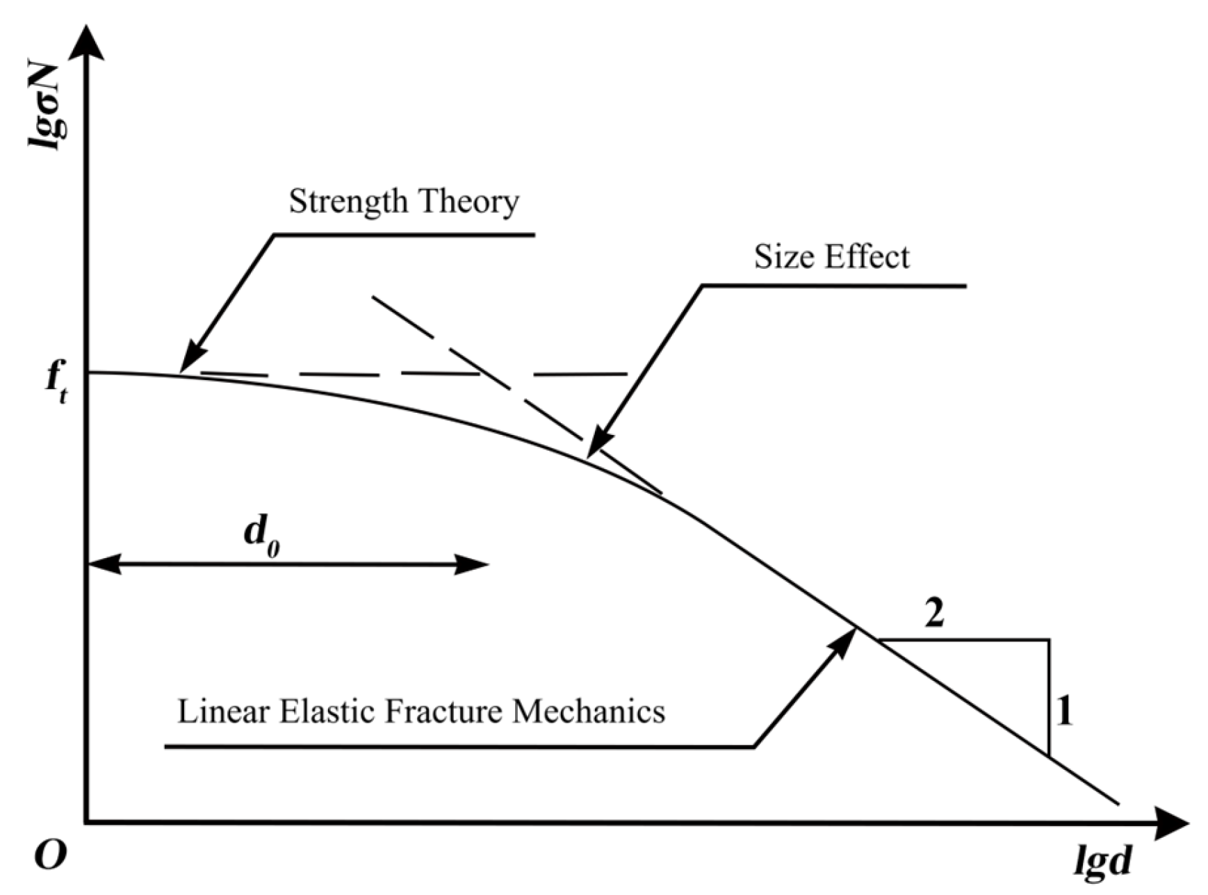
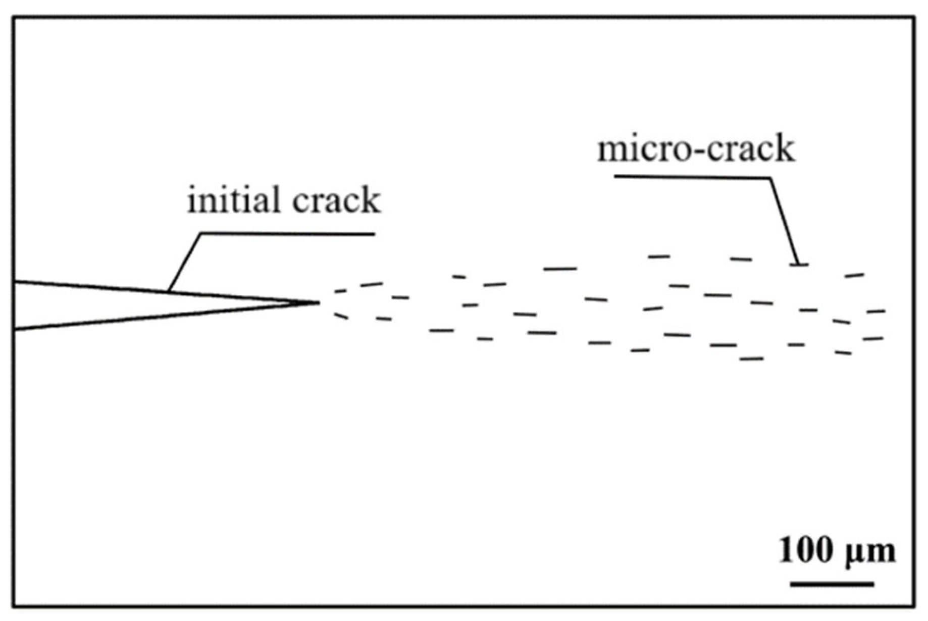
2.2. Failure Characteristics of Semi-Rigid Base Materials

A semi-rigid base is constructed with a composite material composed of cement, lime, fly ash, soil, aggregate, and other materials. The mechanical adhesion characteristics of the raw materials and their interfaces affect the overall performance of the material after molding. During the construction of a semi-rigid base, the bleeding or drying shrinkage of the material produces micro-cracks, and in the stable granular material containing aggregate, there are many micro-cracks (called “joints”) on the interface between the binder and aggregate, and even if the base is well poured, there are many unavoidable micro-cracks and initial defects. Comparatively speaking, the stiffness of the semi-rigid base material is weakened compared to the rigid base material due to the higher number of micro-cracks (i.e., original defects) in the initial formation state of the inorganically bound stabilized class of materials.
In the fracture mechanics of nonmetallic materials, structural damage and the development of damage is the process of expansion of the original defects, that is, the destruction process of a semi-rigid base. In essence, it is the process of the expansion of existing microcracks under the action of external forces, including crack initiation, crack stability expansion, and crack destabilization of the three states. The initial crack of crack initiation is not the micro-crack of the initial defect of the material. The initial defective micro-crack is a kind of dissimilated microstructure, which is formed in the formation process of the strength of the binder under the action of the no-load external force due to the change in the humidity and temperature of the material. Due to the development of various mixture materials, the possibility of the initial defective micro-crack itself forming the initial crack is small. The initial crack that causes crack initiation is formed after the mixture strength is stable through the action of external force and fatigue load, and the stress at the tip of the micro-crack accumulates continuously, as shown in Figure 3.
Under an external load, when the load and action times are relatively small, there is no obvious macroscopic performance of the base, and the micro-level combined with the weak position of the interface leads to the formation of new interface micro-cracks. When the load or load times increase, the internal micro-cracks further develop into initial cracks, forming macroscopic cracks. At the same time, in addition to the material self-generated micro-cracks, during macro-crack propagation, new micro-cracks still appear due to the stress concentration at the tip, which leads to further crack propagation. The initial damage micro-crack is formed by the accumulation of damage through external forces, and then the initial crack is formed, which runs through the macro-crack, and the macro-crack expands and interweaves, and so on, resulting in a decrease in the strength of the semi-rigid plate. Multiple initial cracks can be formed in the base at the same time or successively. With the increase in load or fatigue strength, the cracks enter the stable growth stage, and the cracks further extend and finally enter the unstable state of cracks, which is manifested by the fracture of cement concrete slabs and the fragmentation of large areas of the semi-rigid base. Eventually, the pavement structure breaks down as the cracks extend into the surface layer.

2.3. Adaptive Conditions for In Situ Softening of Semi-Rigid Base

The concept of the in situ softening utilization of semi-rigid base asphalt pavements mainly focuses on the base. In contrast, the pavement structure is composed of multi-level systems, and the mechanical empirical method of layered elastic system theory is primarily used in the design. The surface layer can be divided into a single layer, a double layer, and three layers, which should be flat and durable, mainly providing the functions of wear resistance, crack resistance, and rutting resistance. As the main bearing capacity component layer, the base course is selected according to the material modulus and design requirements. In addition, to improve the overall stability of the pavement structure in different use environments and enhance the stress–strain diffusion effect of each layer of the layered system, functional cushions can be set in the structural layer, as required, to enhance the use efficiency of the overall structure. With the continuous progress of technology and theory, a variety of semi-rigid base function evaluations can be realized, which is of significance to the realization of the in situ softening utilization of semi-rigid bases. The following suggestions, based on the state of the base, are for maintenance reference only:
(1) When the pavement structure of the semi-rigid base and the middle and lower layers remain intact, most of the cracks do not run through the surface layer. Mostly, only skidding badly, flooding oil, loose and slight rutting, and so on are problematic due to the surface layer of compressed dense deformation, stone abrasion, asphalt adhesion decline, aging and deterioration, and other reasons. If the overall structural strength still meets the bearing capacity requirements at this time, surface layer functions can be improved by using methods such as overlaying, a gravel sealing layer, and overlaying according to different situations. When the base course and the middle and lower surface course of the pavement structure remain intact, the surface layer is damaged in a large area, and the overall structural strength still meets the bearing capacity requirements, the surface layer can be milled and resurfaced to maximize the benefits of the pavement structure and function, such as the driving comfort.
In addition, after the above pavement structures are maintained and repaired, relevant monitoring should be carried out according to the construction life of the road. If the pavement is still newly constructed, regular surface observation should be carried out. If the pavement construction period has reached the maintenance period, non-destructive testing can be carried out to observe the performance of the other structural layers, and the abnormal sections of structural layers should be continuously monitored, and the damage development direction can be predicted by numerical simulation to formulate a maintenance plan in advance;
(2) Usually, it is considered that temperature stress, fatigue cracks, shear strength, interlayer bonding strength, compaction and deformation of asphalt surface materials, water damage, and other reasons cause the overall surface layer to remain relatively intact, resulting in cracking, block cracking, rutting, displacement, potholes, transverse and longitudinal cracks, and other phenomena. The following characteristics also occur: the overall cracking of the asphalt surface layer, significant changes in thickness and porosity of the structural layer, the detachment of the surface layer from the base, low splitting strength of the asphalt mixture in the surface layer, the crack development pattern of the wider upper and thinner lower parts, and a high water permeability coefficient.
Under these conditions, the surface layer needs to be milled and resurfaced. When the strength of the base meets the standard of the road surface drive requirements, the asphalt surface layer can be directly milled and resurfaced. When the bearing capacity of the base structure layer is insufficient, the surface layer can be resurfaced after the base is reinforced. Micro-cracking treatment of the base can also be carried out after the rigidity of the semi-rigid base is reduced, and the base, after micro-cracking treatment, is directionally cracked to form blocks with specific grain diameters. After re-evaluation of the material properties, it can be reused in the process of pavement structure remodeling. To respond to the call for intensive resources, it is advocated to use surface milling materials for granular soft recycling to solve the problem of waste surface milling materials;
(3) When a large area of damage occurs to the base or sub-base of the road surface, it has already developed to the entire base, resulting in loose damage to the base, insufficient overall strength of the road structure, and a crack morphology that is wider at the bottom and narrower at the top. The unconfined compressive strength of the base material is low, which is caused by multiple forces, such as base structure fatigue, temperature stress, and water infiltration. At this point, it is necessary to carry out base milling and re-paving. After evaluating the milling materials, it is recommended to prioritize the surface-based granular softening and regeneration repair method, which has the advantages of resource conservation, simplicity, and efficiency;
(4) When the base structure is unstable, it is manifested by base structure deformation, uneven settlement, serious longitudinal cracks, a high moisture content of base soil, uneven soil quality, and other phenomena. At this time, the bearing capacity of the base structure layer is insufficient, and overall reconstruction of the base and pavement structure is needed according to the demands.
This paper examines a typical semi-rigid base pavement featuring a surface layer of 150 mm, a base layer of 350 mm, a sub-base layer of 150 mm, and a soil layer of 500 mm. When the crack density in the semi-rigid base layer ranges from 20 to 40, milling and resurfacing of the surface layer are required. If the base layer’s strength meets the standards for pavement driving requirements, direct asphalt layer milling and resurfacing can be conducted. If the carrying capacity of the base structural layers is insufficient, reinforcement of the base can be performed after the surface-layer resurfacing, or micro-cracking treatment of the base can be applied. In cases where the crack density in the semi-rigid base pavement reaches 40 to 80 per 100 m or when there is a larger area of damage at the base or sub-base level, the issue has escalated to affect the entire base layer. This results in looseness and damage to the base and a deficiency in the overall strength of the pavement structure. In such instances, granular-type softening regeneration methods can be employed. It is important to note that actual engineering applications involve more complex pavement structural layer designs and crack formations. The information provided herein serves as a reference and may require adaptation to specific situations.

3. Numerical Model

The finite element numerical analysis method was used for the whole model, and Ansys software was used to establish the two-dimensional cracking density pavement model and the three-dimensional semi-rigid cracking block-size model. The foundation’s base was assumed to be fully supported, with lateral variations neglected.

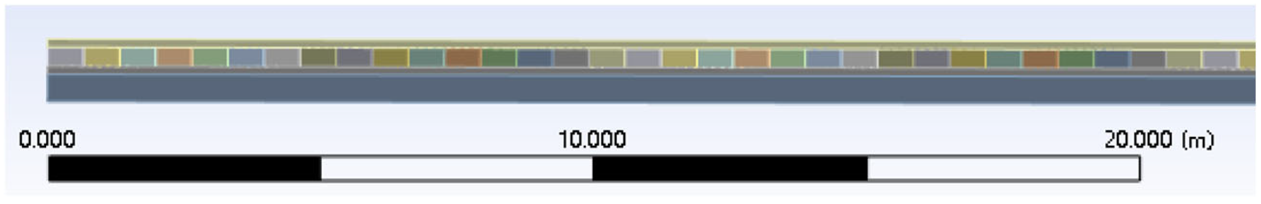
3.1. Base Cracking Density Effect Modeling

To study the influence of the change in semi-rigid base crack density on the reflection expansion of the surface layer, the influence model of the overall pavement crack density was established. The crack width of the semi-rigid base was set as 0.5 mm, and the load form was a 100 kN uniformly distributed load. The crack density model was set as shown in Table 1.
A semi-rigid base refers to a base course paved with soil stabilized by inorganic binders, such as cement, lime, etc. This type of base can form a slab and possesses a certain degree of flexural strength, making it a widely used structural layer in pavements. It has a certain degree of rigidity and can effectively transfer traffic loads. It also has good tensile, fatigue resistance, and water stability. Furthermore, cement-treated materials in semi-rigid pavements also include materials such as soil cement and full-depth reclamation (FDR) with cement. The calculation parameters of the pavement structure are shown in Table 2.
Due to the relatively large pavement model and crack length and width, the first 20 m model was intercepted, with the crack density 5/100 m and 150/100 m models, as shown in Figure 4, Figure 5, Figure 6, Figure 7, Figure 8 and Figure 9. In this study, the cracks at 50 m from the center of the pavement model are taken as the main object of the tip to study the most unfavorable trend of pavement reflection crack expansion.

3.2. Cracking Block-Size Effect Modeling

A semi-rigid base asphalt pavement can be micro-cracked as needed in its later service state. After micro-cracking and compaction, the bearing capacity of the semi-rigid base varies with the size of the cracking blocks and the modulus of the base. Using the finite element numerical method, the rigid elements with a stiffness of 9000 MPa were used to connect the cracking blocks to simulate the moderate friction and extrusion state between the cracking blocks after compaction. The distribution of rigid elements is shown schematically in Figure 10 [27,28].
As shown in Figure 5, the different semi-rigid base model cracking block sizes were 2 m, 1 m, 80 cm, 50 cm, 37.5 cm, 25 cm, and 15 cm, respectively, and the overall model was used with a Poisson’s ratio of 0.25 and a modulus of elasticity of 2100 MPa, 2200 MPa, 2300 MPa, 2400 MPa, 2500 MPa, and 2600 MPa, and the load form was a 100 kN uniform load [29]. When the side length of the cracking block was less than 0.35 m, the thickness of the model was the same as the side length. To simulate actual situations, the connection depth of the rigid element decreases with the decrease in the size of the cracking block. Due to the limitation of the finite element model capacity and calculation force, the size of the calculation model also decreases accordingly [30,31,32,33]. The size, the connection length of the rigid element, and the size of the cracking block model of different sizes are shown in Table 3.

4. Base Cracking Properties

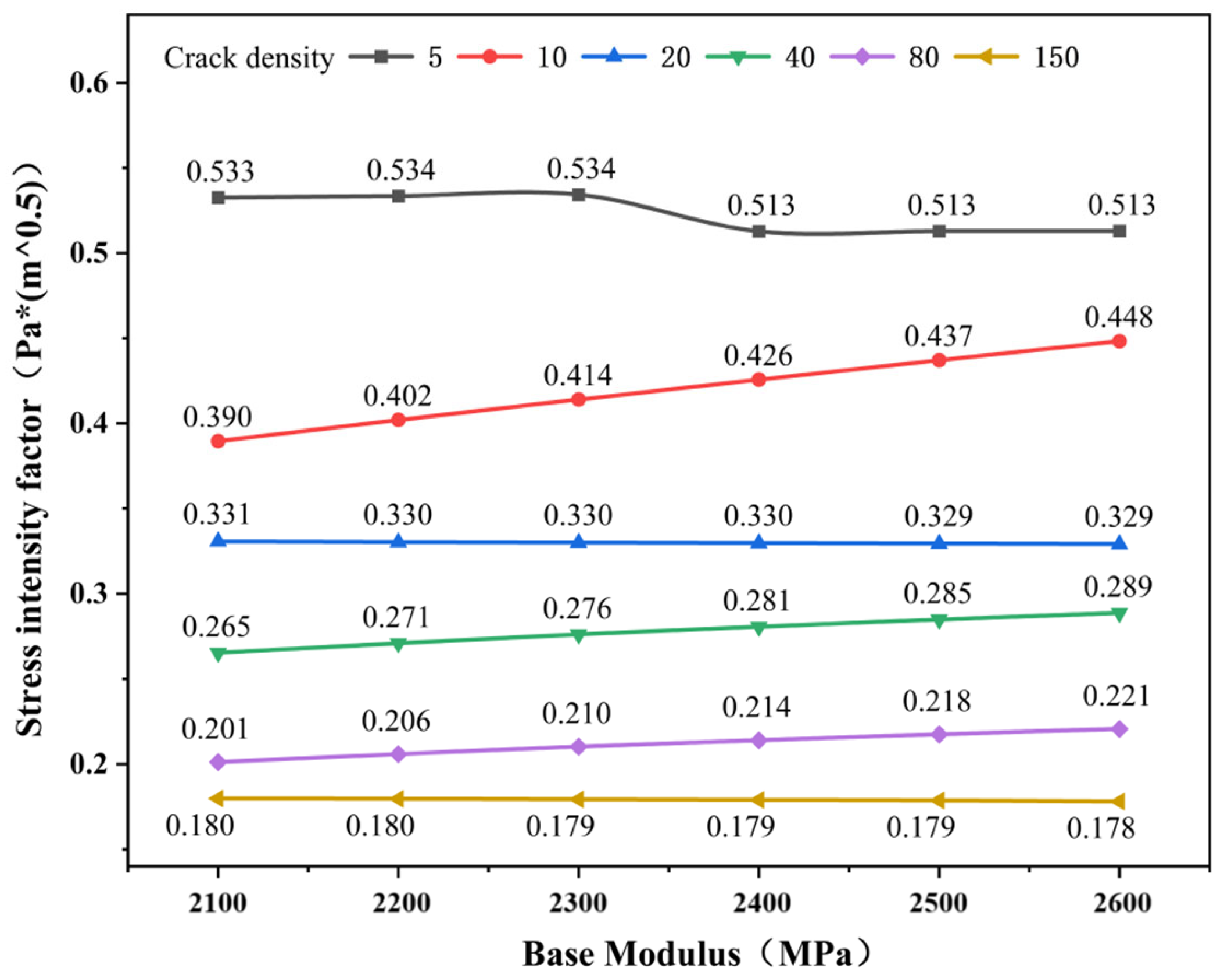
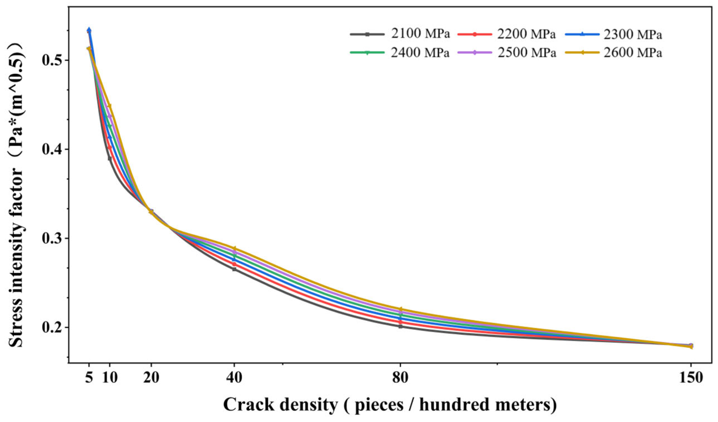
4.1. Cracking Properties Based on Different Crack Densities

To study the overall pavement reflection crack expansion trend in the semi-rigid base modulus under the same crack density condition, the center crack stress intensity factor set at 50 m for the same crack density pavement model was extracted, as shown in Figure 11.
As shown in Figure 11, at the same crack density of a semi-rigid base, the smaller the crack density, the larger the overall value of the pavement structure center stress intensity factor. When the pavement structure’s semi-rigid base crack density at 100 m is 5, the modulus of the semi-rigid base is 2100 MPa, 2200 MPa, and 2300 MPa, respectively. The center crack stress intensity factor is the same. When the modulus of the base is 2400 MPa, 2500 MPa, and 2600 MPa, the center crack stress intensity factor is the same and smaller than the first three moduli. The finite element internal mesh division and interlayer node adaptive causing jumps are the main reasons for this situation when the surface layer modulus is 2400 MPa. When the semi-rigid base is connected with the surface layer and the modulus is the same, the crack calculation node produces jumps and changes the calculation path. Due to the large stress intensity factor at this time, the connection between 2300 MPa and 2400 MPa is not completely linear when the fracture density is 5, which does not affect the overall trend judgment. The data of the central crack stress intensity factor at 50 m of different modulus pavement models are shown in Table 4.
When the density of 100 m cracks in the base of the pavement structure is 10, the center crack stress intensity factor increases with the modulus, and the change is more obvious. When the 100 m crack density of the base is 20, the center crack stress intensity factor tends to be the same. When the density of the 100 m base cracks is 40 and 80, the center crack stress intensity factor increases slowly with the modulus, and the magnitude is consistent. When the 100 m crack density of the base is 150, the center crack stress intensity factor tends to be the same. The development trend of the reflective cracks on the overall pavement is shown in Figure 12.
As shown in Figure 12, when the modulus of the semi-rigid base is different, the stress intensity factor of the center crack of the pavement structure decreases with the increase in the number of cracks. The more cracks there are, the less likely the cracks will expand. When the crack density is around five pieces, the stress intensity factor values of multiple modulus center cracks are relatively high. Therefore, when constructing a semi-rigid base, contraction joints can be designed within a hundred meters to reduce structural impact. When carrying out maintenance and repair, a pavement structure with a crack density of 5~10 pieces within a hundred meters can be mainly maintained by surface layer maintenance, according to the situation, using cover paving, a paving gravel sealing layer and cover, and other methods to improve the function of the pavement layer. When the crack develops to 10 pieces, the greater the modulus of the semi-rigid base, the greater the stress intensity factor of the central crack, which indicates that the crack has entered a stable development stage. When the modulus is greater, a crack is easy to expand, but the expansion depth is smaller, which shows that the loose degree of the whole structure gradually increases, and the structural integrity decreases. The smaller the modulus, the smaller the stress intensity factor of the central crack, which shows that the overall structure is cracked from plate to block, and the structural integrity is reduced. Therefore, when the crack density of the base course has reached 10~20 pieces, the surface course needs to be milled and resurfaced. If the strength of the base course meets the requirements of pavement driving, the asphalt surface course can be milled and resurfaced directly. If the bearing capacity of the base course structure is insufficient, the surface course can be resurfaced after the base course is reinforced. When a crack develops to 20 pieces, the stress intensity factor of the central crack of the multi-modulus pavement structure tends to be consistent, which indicates that the development of the crack of the multi-modulus pavement structure is less affected by the modulus, the main crack of the base course develops through it, and the integrity of the plate decreases. At this time, the micro-cracking treatment of the base course can be carried out, the rigidity of the semi-rigid base is artificially reduced, the block structure is retained, and its performance can be re-evaluated. And it can be reused in the process of remodeling the pavement structure. When the crack density of the pavement structure is greater than 40 pieces, the change in cracks slow down, and the whole base is in a loose state. At this time, the base milling material can be used for semi-rigid base granular softening regeneration, or the surface layer-semi-rigid base granular softening regeneration can be directly carried out to respond to the call of resource recycling. When the crack density of the semi-rigid base is greater than 150 pieces, the stress intensity factor of the central crack of the multi-modulus pavement structure tends to be consistent, indicating that the overall function of the pavement has been lost, and the pavement needs to be rebuilt as a whole.
Based on the 100 m crack density and modulus changes of the overall pavement model, the analysis of the central crack stress intensity factor shows that when the modulus of the semi-rigid base is in the range of 2100 MPa to 2600 MPa, the corresponding softening recommendations for the pavement structure are as shown in Table 5.
To sum up, when the crack density of semi-rigid base pavement is 20~40 pieces, the micro-cracking softening method can be used, and when the crack density of semi-rigid base pavement is 40~80 piece, the granular softening regeneration method can be used. It is important to note here that the study only analyzed typical semi-rigid base pavements, i.e., surface (150 mm), base (350 mm), sub-base (150 mm), and soil (500 mm) structures. To simulate the changing state of the semi-rigid base layer in the late stage of maintenance and repair, the modulus change interval of the base layer was chosen to be relatively smaller. In actual projects, the pavement structural layer design, crack form, and other specific circumstances are more complex. This study is for reference only.

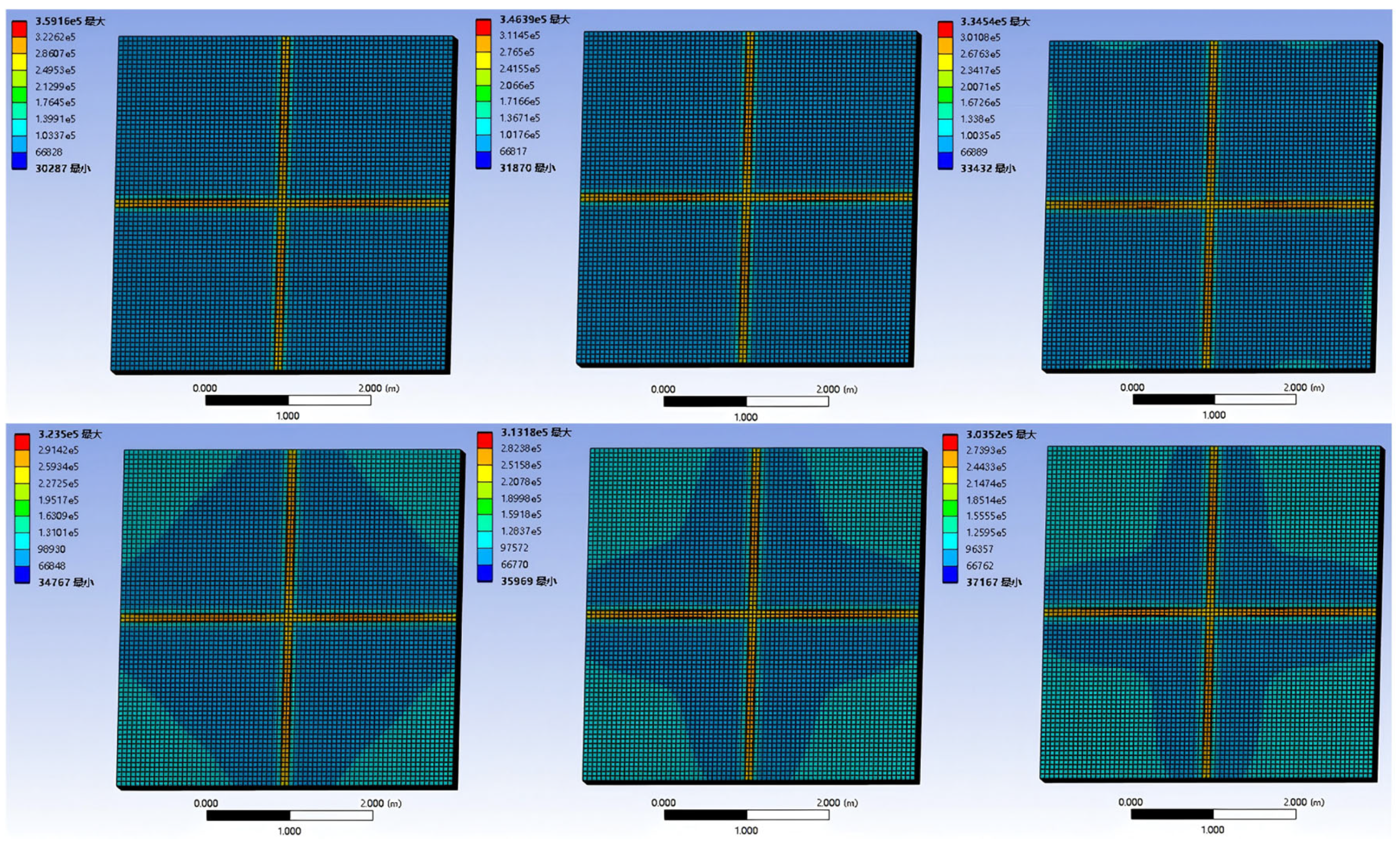
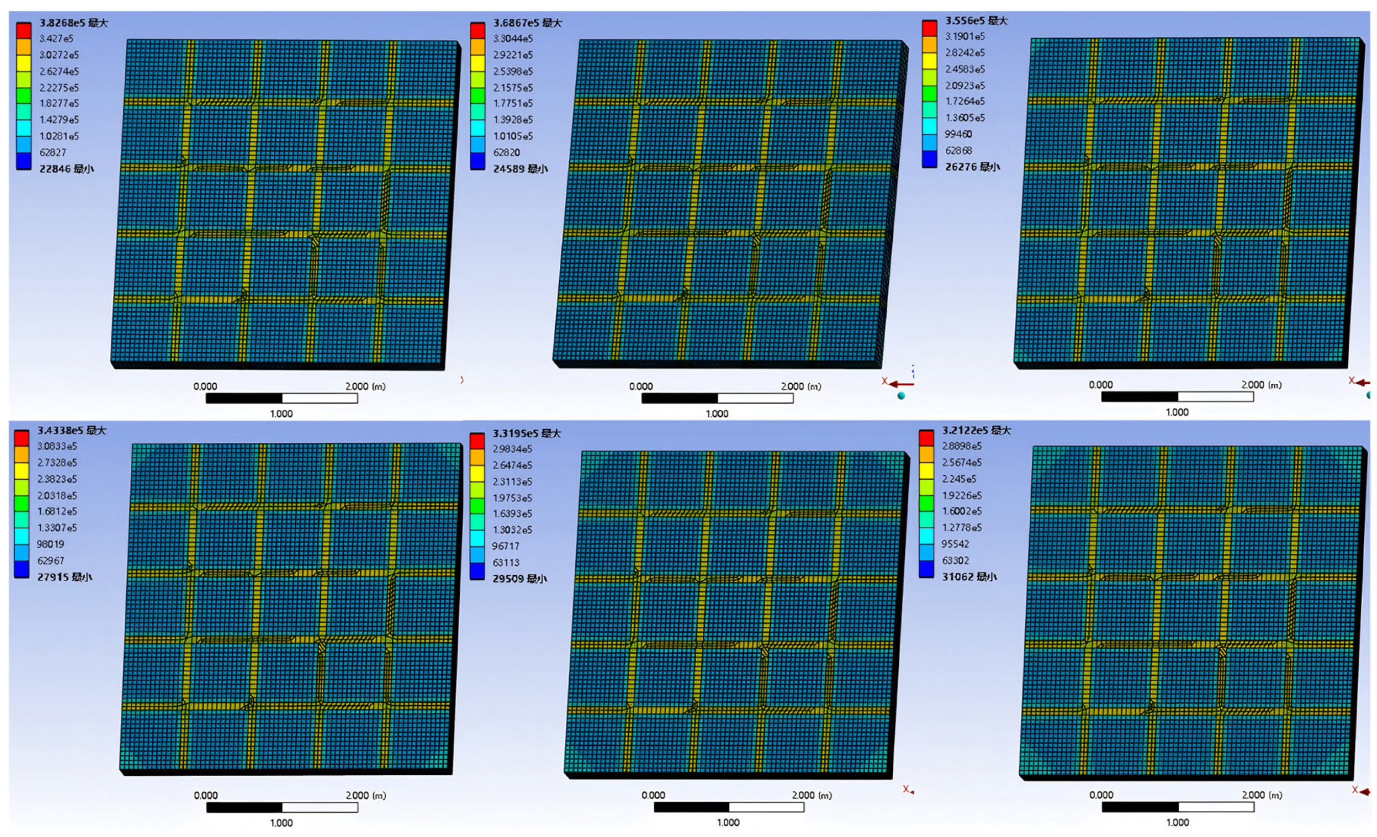
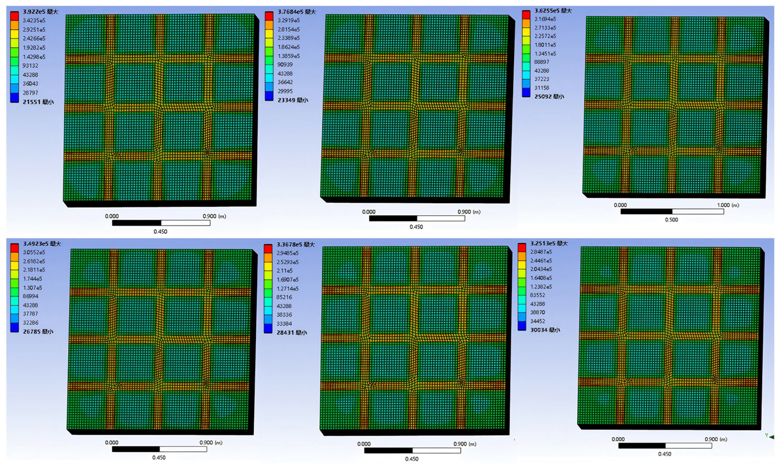
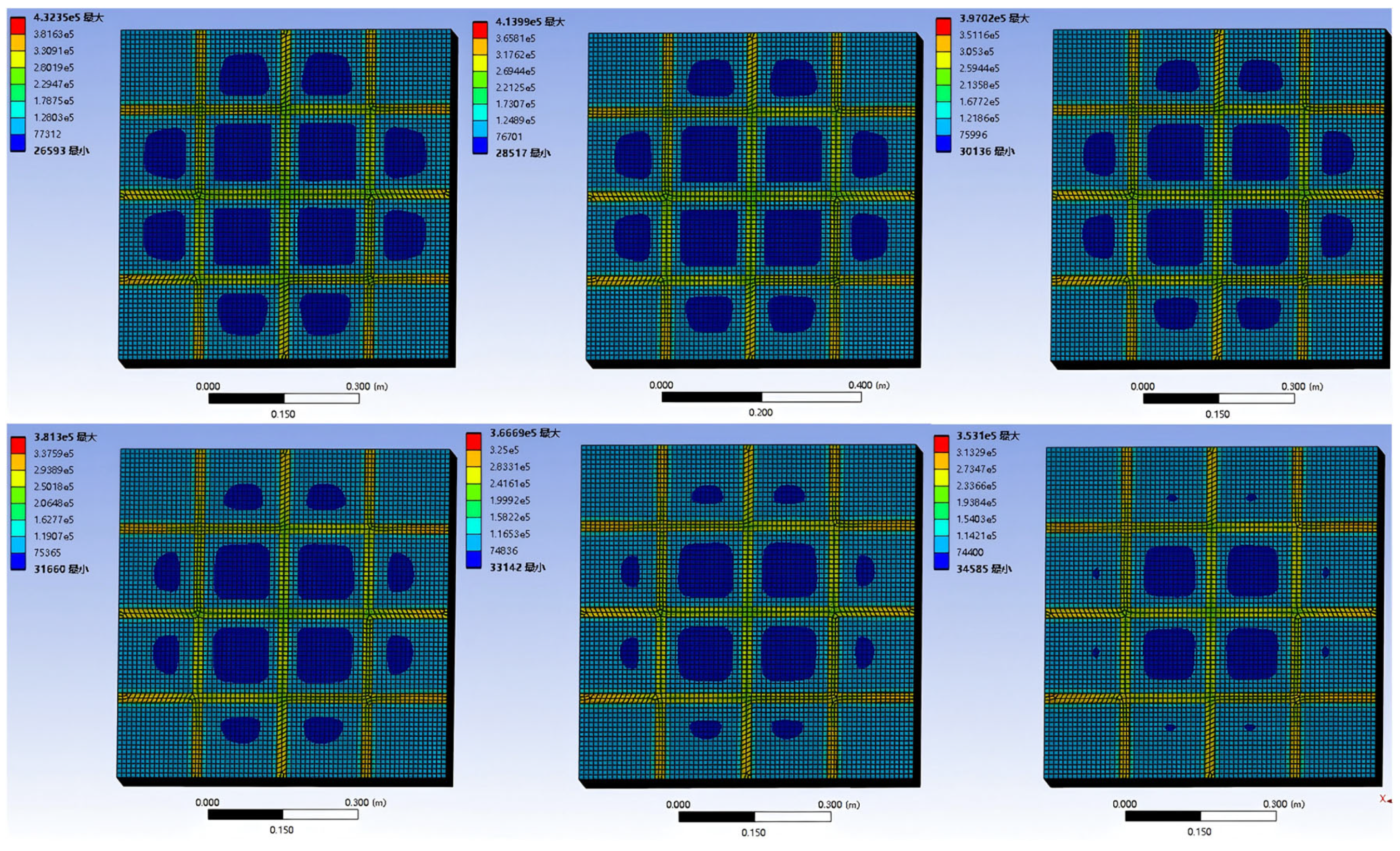
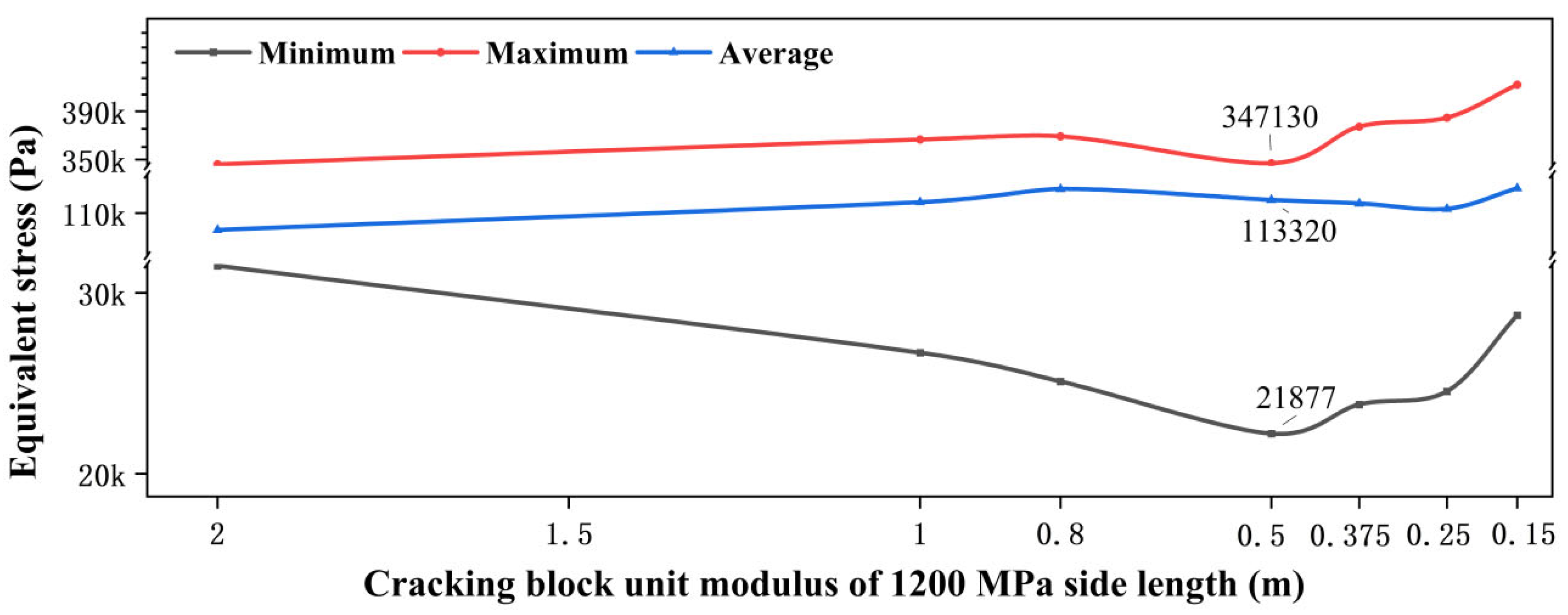
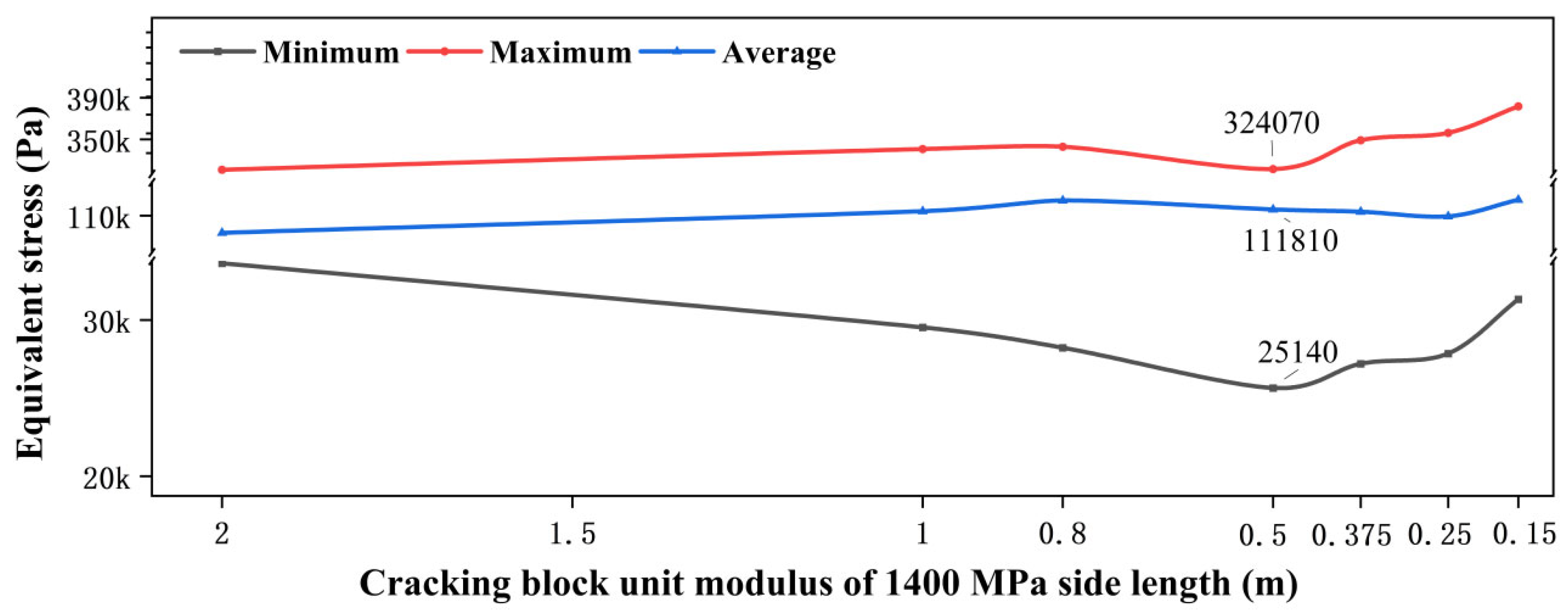
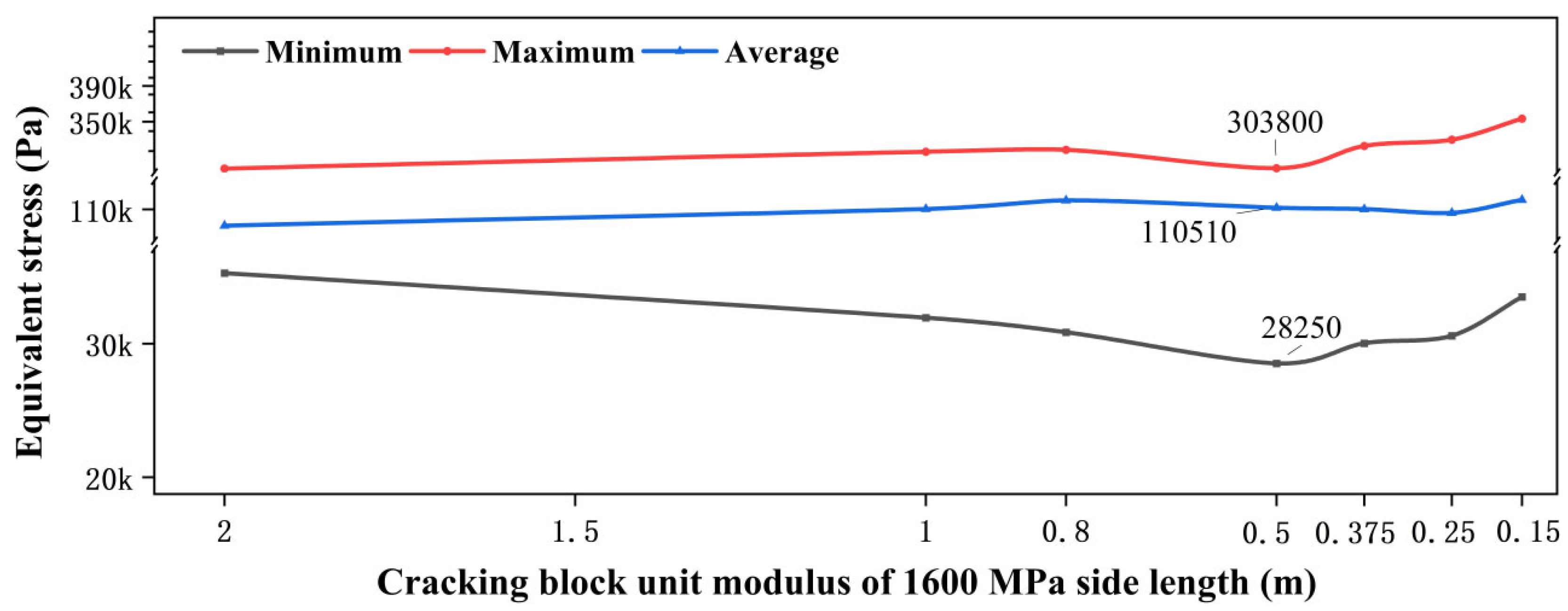
4.2. Bearing Capacity Characteristics Based on Different Cracked Block Sizes

Using finite element software to establish single-layer models of semi-rigid substrates with different moduli, the crack block sizes were 2 m, 1 m, 80 cm, 50 cm, 37.5 cm, 25 cm, and 15 cm, respectively. The equivalent stress cloud maps of crack blocks with different sizes were calculated, as shown in Figure 13, Figure 14, Figure 15, Figure 16, Figure 17, Figure 18 and Figure 19. (The top three frames from left to right represent the modulus of the base at 2100 MPa, 2200 MPa, and 2300 MPa, while the bottom three frames from left to right represent 2400 MPa, 2500 MPa, and 2600 MPa.)
As shown in Figure 13, when the six moduli’s semi-rigid base cracking block size is 2 m, the minimum equivalent stress value is the largest, the maximum equivalent stress value is close to the lowest value, and the average stress value is the lowest, indicating that at this time, the semi-rigid base load-bearing mode presents the characteristics of the plate-body type of force, which is mainly dominated by the plate diffusion averaging effect, and friction force is less involved.
As shown in Figure 14, when the size of the cracking block is 1 m, the minimum equivalent stress value of the cracking block with six moduli decreases, and the maximum equivalent stress value and the average stress value increase, which indicates that the bearing mode of the cracking block changes from the plate body to the block body.
As shown in Figure 15, when the size of the cracking block is 80 cm, the minimum equivalent stress value of the cracking block with six moduli continues to decrease, the maximum equivalent stress value continues to increase, and the average stress value increases to the maximum value, which means that the stress of the block bearing mode reaches the maximum at this time.
As shown in Figure 16, when the size of the cracking block is 50 cm, the minimum equivalent stress value of the cracking block with six moduli is reduced to the minimum, the maximum equivalent stress value is reduced to the minimum, and the average stress value is reduced, which represents that the edge friction force simulated by the rigid element enters the main bearing sequence and forms the stress mode of bearing together with the block.
As shown in Figure 17, when the size of the cracking block is 37.5 cm, the minimum equivalent stress value of the cracking block with six moduli rises, the maximum equivalent stress value rises, and the average stress value continues to decrease. At this time, the external force is borne by the friction force at the edge of the rigid element and the block body, and the maximum, minimum, and average equivalent stresses are at the extreme points. Based on the cloud diagram, it can also be seen that the 37.5 cm cracking block has the most uniform force, there is no stress loss in the middle and stress concentration in the rigid unit, and the rigid unit inside the block and at the edge of the block is uniformly carrying the external force, which belongs to the most effective linking force state.
As shown in Figure 18, when the size of the cracking block is 25 cm, the minimum equivalent stress of the cracking block with six moduli continues to rise, the maximum equivalent stress continues to rise, and the average stress value decreases to the vicinity of the minimum value, which means that the edge friction simulated by the rigid element is the main bearing form at this time, and the stress reduction in the middle of the block no longer belongs to the bearing capacity sequence, which can also be seen from the program. The actual situation belongs to the failure of the middle part of the block.
As shown in Figure 19, when the size of the cracking block is 15 cm, it belongs to edge friction and block failure, and the structure is loose and no longer has bearing capacity.
The stress distribution of cracked blocks of different sizes with the same modulus is shown in Figure 20, Figure 21, Figure 22, Figure 23, Figure 24 and Figure 25. As shown in the figure, the trend of equivalent stress changes in different base moduli when the size of the cracked block changes is consistent, and the minimum stress, maximum stress, and average stress of the six moduli increase with the modulus.
Based on the analysis results of the semi-rigid base cracking block-size influence model, it is concluded that when the modulus of the semi-rigid base is between 2100 MPa and 2600 MPa, the corresponding mechanical properties of different sizes after micro-cracking treatment and compaction treatment of the semi-rigid base are as shown in Table 6. Due to the difference between the base characteristics in the actual project and the simulation results under the ideal state of the finite element in the study, the size of the cracking block listed in the table is approximate.
From the above, it can be concluded that in the treatment of microcracking on a semi-rigid base, the maximum benefit of microcracking treatment can be achieved when the size of the cracking block is about 0.25 m to 0.5 m, effectively utilizing the remaining bearing capacity of the semi-rigid base. It should be noted that the study only analyzed the crack block sizes corresponding to typical semi-rigid bases, namely, the six moduli’s 350 mm bases. It cannot be denied that the road surface in actual engineering is affected by environmental factors, and further detailed analysis should be conducted based on the situation.

5. Conclusions

(1) In Situ Softening Framework and Treatment Strategies: We developed a fracture mechanics-based in situ softening framework that integrates a crack-density–stiffness model and a micro-crack block-size bearing model via finite element analysis. Based on surface milling and the need for base overhaul, two targeted softening treatments are prescribed: (i) micro-cracking softening, involving the physical compaction of fine cracks and (ii) granular softening, using emulsified or foamed asphalt particles. Both approaches aim to maximize the residual bearing capacity and extend the service life of semi-rigid bases under varied crack conditions;
(2) Block-Size–Dependent Bearing Mechanisms: Based on the analysis of the bearing capacity of different cracked blocks after the micro-cracking treatment of a semi-rigid base layer, it is concluded that a cracked block size of about 2 m is dominated by the plate-type bearing force, and 1 m is dominated by the block-type bearing force. The block bearing force reaches the highest point of the main bearing mode when the size of the cracked block is about 0.8 m and edge friction starts to bear the force in the main mode, together with the block-type bearing force at 0.5 m. A cracked block size of about 0.375 m is the most effective linking force state as the internal and edge friction of the block uniformly carry the external force, 0.25 m is most effective when the middle of the block has already failed, and 0.15 m is most effective when the edge friction and the block bearing the force have failed;
(3) Quantitative Softening Thresholds and Optimal Treatment Scale: The models indicate that micro-cracking softening is most effective for crack densities of 20–40 cracks/100 m, yielding an 18% reduction in peak stress intensity and a 12% gain in bearing capacity, while granular softening is preferred for densities of 40–80 cracks/100 m, achieving a 22% SIF reduction and 15% capacity improvement. Furthermore, treating blocks in the 0.25–0.5 m size range optimally balances remediation effort with performance gains, enabling precise assessments of the residual bearing capacity;
(4) Limitations and Future Validation: These conclusions are derived from theoretical FEM simulations under idealized conditions. Real-world factors—material heterogeneity, variable layer thicknesses, and complex crack morphologies—were not incorporated. Accordingly, future work will focus on laboratory and in situ experiments (e.g., controlled beam-on-base loading tests and field settlement measurements) to empirically validate, calibrate, and refine the proposed framework for practical application.

Author Contributions

Conceptualization, J.P. and L.Y.; methodology, R.L.; software, L.Y.; formal analysis, H.H.; investigation, Z.X.; resources, D.H.; data curation, L.Y.; writing—original draft preparation, L.Y.; writing—review and editing, L.Y. and C.Y.; visualization, D.H.; supervision, R.L.; project administration, J.P.; funding acquisition, L.Y. All authors have read and agreed to the published version of the manuscript.

Funding

This work was sponsored by the Young Doctor Project of the Xinjiang “Tianchi” Talent Introduction Plan and the National Natural Science Foundation of China (Grant No. 52178408). The authors gratefully acknowledge their financial support. And The APC was funded by the Young Doctor Project of the Xinjiang “Tianchi” Talent Introduction Plan.

Data Availability Statement

Data will be made available on request.

Conflicts of Interest

The authors declare no conflict of interest.

References

  1. Yu, L.; Wu, Y.; Meng, Y.; Huang, G.; Li, R.; Pei, J. Study on fatigue crack propagation failure in semi-rigid base. Constr. Build. Mater. 2023, 409, 134007. [Google Scholar] [CrossRef]
  2. Botvina, L.R. Damage Evolution and Fracture in Terms of The Theory of Phase Transition. Procedia Struct. Integr. 2019, 14, 26–33. [Google Scholar] [CrossRef]
  3. Maurizi, M.; Berto, F. 3D Effects on Fracture Mechanics. Procedia Struct. Integr. 2020, 25, 261–268. [Google Scholar] [CrossRef]
  4. Shahbazpanahi, S.; Karim, H.; Abdullah, W.; Reuter, U.; Mosavi, A.H. Crack Propagation Modeling of Strengthening Reinforced Concrete Deep Beams with CFRP Plates. Mater. Res. Express 2021, 8, 095502. [Google Scholar] [CrossRef]
  5. Clayton, J.D. Finsler Differential Geometry in Continuum Mechanics: Fundamental Concepts, History, and Renewed Application to Ferromagnetic Solids. Math. Mech. Solids 2021, 27, 910–995. [Google Scholar] [CrossRef]
  6. Barras, F.; Aldam, M.; Roch, T.; Brener, E.A.; Bouchbinder, E.; Molinari, J.-F. The Emergence of Crack-like Behavior of Frictional Rupture: Edge Singularity and Energy Balance. Earth Planet. Sci. Lett. 2019, 531, 115978. [Google Scholar] [CrossRef]
  7. Paglialunga, F.; Passelègue, F.X.; Brantut, N.; Barras, F.; Lebihain, M.; Violay, M. On the Scale Dependence in The Dynamics of Frictional Rupture: Constant Fracture Energy Versus Size-dependent Breakdown Work. Earth Planet. Sci. Lett. 2021, 584, 117442. [Google Scholar] [CrossRef]
  8. Doitrand, A.; Sapora, A. Nonlinear Implementation of Finite Fracture Mechanics: A Case Study on Notched Brazilian Disk Samples. Int. J. Non-Linear Mech. 2020, 119, 103245. [Google Scholar] [CrossRef]
  9. Gvirtzman, S.; Fineberg, J. Nucleation Fronts Ignite the Interface Rupture That Initiates Frictional Motion. Nat. Phys. 2021, 17, 1037. [Google Scholar] [CrossRef]
  10. Rajbongshi, P.; Das, A. Estimation of Temperature Stress and Low-Temperature Crack Spacing in Asphalt Pavements. J. Transp. Eng. 2009, 135, 745–752. [Google Scholar] [CrossRef]
  11. Alavi, M.Z. Comprehensive, Methodologies for Analysis of Thermal Cracking in Asphalt Concrete Pavements. Bachelor’s Thesis, University of Nevada, Reno, NV, USA, 2013. [Google Scholar]
  12. Park, J.-W.; Ryu, S.; Oh, H.; Cho, Y.-H. Relationship Between Cracking Closure and Zero Stress Temperature in Concrete Pavements. Ksce J. Civ. Eng. 2019, 23, 3961–3967. [Google Scholar] [CrossRef]
  13. Golrokh, A.J.; Lu, Y. An Experimental Study of The Effects of Climate Conditions on Thermography and Pavement Assessment. Int. J. Pavement Eng. 2019, 22, 1030–1041. [Google Scholar] [CrossRef]
  14. Xie, P.; Wang, H. Analysis of Temperature Variation and Thermally-Induced Reflective Cracking Potential in Composite Pavements. Transp. Res. Rec. 2020, 2674, 177–188. [Google Scholar] [CrossRef]
  15. Zhang, H.; Gao, P.; Zhang, Z.; Pan, Y. Experimental Study of The Performance of a Stress-absorbing Waterproof Layer for Use in Asphalt Pavements on Bridge Decks. Constr. Build. Mater. 2020, 254, 119290. [Google Scholar] [CrossRef]
  16. Adam, Q.; Englmair, G.; Levenberg, E.; Skar, A. Active Mitigation of Low-Temperature Cracking in Asphalt Pavements. In Proceedings of the RILEM International Symposium on Bituminous Materials, Lyon, France, 14–16 December 2020; Springer Publishing: Cham, Switzerland, 2020; Volume 21–23. [Google Scholar]
  17. Yu, B.; Lu, Q.; Yang, J. Evaluation of Anti-Reflective Cracking Measures by Laboratory Test. Int. J. Pavement Eng. 2013, 14, 553–560. [Google Scholar] [CrossRef]
  18. Gonzalez-Torre, I.; Calzada-Perez, M.A.; Vega-Zamanillo, A.; Castro-Fresno, D. Evaluation of Reflective Cracking in Pavements Using A New Procedure That Combines Loads with Different Frequencies. Constr. Build. Mater. 2015, 75, 368–374. [Google Scholar] [CrossRef]
  19. Horníček, L.; Zikmund, R. Mechanical Stabilization of Intermediate Granular Layers in Pavement Structures-Laboratory Study. Procedia Eng. 2017, 189, 174–180. [Google Scholar] [CrossRef]
  20. Chen, D.; Hong, F.; Zhou, F. Premature Cracking from Cement-Treated Base and Treatment to Mitigate Its Effect. J. Perform. Constr. Facil. 2011, 25, 113–120. [Google Scholar] [CrossRef]
  21. Zhang, J.; Dai, L.; Zheng, J.; Wu, H. Reflective Crack Propagation and Control in Asphalt Pavement Widening. J. Test. Eval. 2016, 44, 838–846. [Google Scholar] [CrossRef]
  22. Golewski, G.L.; Golewski, P.; Sadowski, T. Numerical modeling crack propagation under model Ⅱ fracture in plain concretes containing siliceous fly-ash additive using XFEM method. Comput. Mater. Sci. 2012, 61, 75–78. [Google Scholar] [CrossRef]
  23. Gracie, R.; Wang, H.W.; Belytschko, T. Blending in the finite element method by discontinuous Galerkin and assumed strain methods. Int. J. Numer. Methods Eng. 2008, 74, 1645–1669. [Google Scholar] [CrossRef]
  24. Gracie, R.; Oswald, J.; Belytschko, T. On a new extended finite element method for dislocations: Core enrichments. J. Mech. Phys. Solids 2008, 56, 200–214. [Google Scholar] [CrossRef]
  25. Dave, E.V.; Buttlar, W.G. Thermal reflective cracking of asphalt concrete overlays. Int. J. Pavement Eng. 2010, 11, 477–488. [Google Scholar] [CrossRef]
  26. Zamora-Barraza, D.; Calzada-Pérez, M.A.; Castro-Fresno, D.; Vega-Zamanillo, A. Evaluation of anti-reflective cracking systems using geosynthetics in the interlayer zone. Geotextile Geomembr. 2011, 29, 130–136. [Google Scholar] [CrossRef]
  27. Yu, L.; Wang, L.; Pei, J.; Li, R.; Zhang, J.; Cheng, S. Structural Optimization Study Based on Crushing of Semi-rigid Base. Electron. Res. Arch. 2023, 31, 1769–1788. [Google Scholar] [CrossRef]
  28. Zhang, H.; Zheng, F.; Zhang, J.; Hu, D.; Minelli, M.; Pei, J.; Sangiorgi, C. Contributions of Fourier-transform infrared spectroscopy technologies to the research of asphalt materials: A comprehensive review. Fuel 2024, 371, 132078. [Google Scholar] [CrossRef]
  29. JTG D50-2017; Specification for Design of Highway Asphalt Pavement. China Highway Specification and Design Institute: Beijing, China, 2017.
  30. Pérez-Acebo, H.; Linares-Unamunzaga, A.; Rojí, E.; Gonzalo-Orden, H. IRI performance models for flexible pavements in two-lane roads until first maintenance and/or rehabilitation work. Coatings 2020, 10, 97. [Google Scholar] [CrossRef]
  31. Pérez-Acebo, H.; Gonzalo-Orden, H.; Findley, D.J.; Rojí, E. Modeling the international roughness index performance on semi-rigid pavements in single-carriageway roads. Constr. Build. Mater. 2021, 272, 121665. [Google Scholar] [CrossRef]
  32. Zu, F.; Du, C.; Han, C.; Xu, L.; Peng, Q. Applicable conditions of room-and-pillar mining goaf treatment methods under a traffic load. Appl. Sci. 2023, 13, 2024. [Google Scholar] [CrossRef]
  33. Yu, L.; Tang, D.; Kang, H.; He, H.; Hu, D.; Li, R.; Pei, J.; Cheng, S. Research on the Stress Characteristics of Reuse of Semi-Rigid Base. Sensors 2024, 24, 8004. [Google Scholar] [CrossRef]
Figure 1. Relationship between material stress–strain curves and crack progression.
Buildings 15 01791 g001
Figure 2. Size transition effect of the base layer.
Buildings 15 01791 g002
Figure 3. Micro-cracks and initial cracks in the mixture.
Buildings 15 01791 g003
Figure 4. Crack density: 5/100 m.
Buildings 15 01791 g004
Figure 5. Crack density: 10/100 m.
Buildings 15 01791 g005
Figure 6. Crack density: 20/100 m.
Buildings 15 01791 g006
Figure 7. Crack density: 40/100 m.
Buildings 15 01791 g007
Figure 8. Crack density: 80/100 m.
Buildings 15 01791 g008
Figure 9. Crack density: 150/100 m.
Buildings 15 01791 g009
Figure 10. Rigid connection model of cracking block.
Buildings 15 01791 g010
Figure 11. Variation of stress intensity factor of crack density at the center of base with the same crack density.
Buildings 15 01791 g011
Figure 12. Change in stress intensity factor of center crack density of base course with different modulus.
Buildings 15 01791 g012
Figure 13. Equivalent stress distribution of 2 m cracked block.
Buildings 15 01791 g013
Figure 14. Equivalent stress distribution of 1 m cracked block.
Buildings 15 01791 g014
Figure 15. Equivalent stress distribution of 80 cm cracked block.
Buildings 15 01791 g015
Figure 16. Equivalent stress distribution of 50 cm cracked block.
Buildings 15 01791 g016
Figure 17. Equivalent stress distribution of 37.5 cm cracked block.
Buildings 15 01791 g017
Figure 18. Equivalent stress distribution of 25 cm cracked block.
Buildings 15 01791 g018
Figure 19. Equivalent stress distribution of 15 cm cracked block.
Buildings 15 01791 g019
Figure 20. Equivalent stress distribution of cracking blocks with different sizes at 2100 MPa base.
Buildings 15 01791 g020
Figure 21. Equivalent stress distribution of cracking blocks with different sizes at 2200 MPa base.
Buildings 15 01791 g021
Figure 22. Equivalent stress distribution of cracking blocks with different sizes at 2300 MPa base.
Buildings 15 01791 g022
Figure 23. Equivalent stress distribution of cracking blocks with different sizes at 2400 MPa base.
Buildings 15 01791 g023
Figure 24. Equivalent stress distribution of cracking blocks with different sizes at 2500 MPa base.
Buildings 15 01791 g024
Figure 25. Equivalent stress distribution of cracking blocks with different sizes at 2600 MPa base.
Buildings 15 01791 g025
Table 1. Distribution of crack density.
Crack density (piece/100 m)510204080150
Model length (m)100100100100100100
Number of model cracks510204080150
Table 2. Calculation parameters of pavement structure [1].
StructuralMaterialModulus of Elasticity (MPa)Poisson’s RatioThickness (mm)
SurfaceAsphalt mixture14000.25150
BaseCement-stabilized aggregate2100/2200/2300/2400/
2500/2600
0.25350
Sub-baseGravel4000.35150
subgradeSoil800.4500
Table 3. Parameters of the cracking block model.
Cracking Block Unit Side LengthNumber of Cracked BlocksRigid Connection DepthModel Length/WidthModel Thickness
2 m2 × 2100 mm4.10 m350 mm
1 m4 × 4100 mm4.30 m350 mm
0.8 m5 × 5100 mm4.40 m350 mm
0.5 m8 × 880 mm4.56 m350 mm
0.375 m4 × 480 mm1.74 m350 mm
0.25 m4 × 430 mm1.15 m250 mm
0.15 m4 × 420 mm0.66 m150 mm
Table 4. Force intensity factor of pavement center crack with different crack density and modulus (Pa*(m^0.5)).
Base Modulus2100 MPa2200 MPa2300 MPa2400 MPa2500 MPa2600 MPa
Crack Density
5 pieces0.53260.53350.53430.51280.51290.5130
10 pieces0.38960.40200.41400.42570.43710.4483
20 pieces0.33060.33020.32990.32960.32930.3290
40 pieces0.26530.27090.27600.28060.28480.2887
80 pieces0.20120.20590.21020.21400.21750.2206
150 pieces0.17980.17960.17930.17900.17870.1781
Table 5. Softening recommendations based on crack density.
A Hundred-Meter Crack in BasePavement ConditionSuggested Curing Methods
Less than 5Newly builtSurface observation
5~10 piecesThe surface layer is slightly damagedOverlay, chipping seal and overlay, etc.
10~20 piecesThe surface layer is completely damagedMilling and planing the surface course and resurfacing the surface course after reinforcing the base course as required
20~40 piecesCrack penetration of base courseMicro-cracking treatment to convert the semi-rigid base into the bottom and lower base
40~80 piecesThe base course is looseSemi-rigid base granular material-type softening regeneration
More than 150 piecesLoss of overall pavement functionOverall reconstruction of pavement
Table 6. Bearing characteristics of cracking blocks with different sizes.
Size of the Cracking Block (Approximate Value)The Main Bearing Mode of External Force
2 mMainly plate-type load-bearing
1 mMainly block-type load-bearing
0.8 mBlock-type bearing force as the highest point of the main mode
0.5 mThe edge friction force begins to participate in the main way and bears the external force, together with the block-type bearing force
0.375 mThe most effective connection stress state and the internal and edge friction of the block uniformly bear the external force
0.25 mThe bearing capacity is uneven, mainly due to edge friction, and the middle part of the block has failed
Less than 0.25 mFailure of edge friction and block-bearing force
Disclaimer/Publisher’s Note: The statements, opinions and data contained in all publications are solely those of the individual author(s) and contributor(s) and not of MDPI and/or the editor(s). MDPI and/or the editor(s) disclaim responsibility for any injury to people or property resulting from any ideas, methods, instructions or products referred to in the content.

