
Behavior of Eccentrically Loaded Concrete-Filled Steel Tube Latticed Columns with Corrugated Steel Plates for Industrial Structures

Abstract
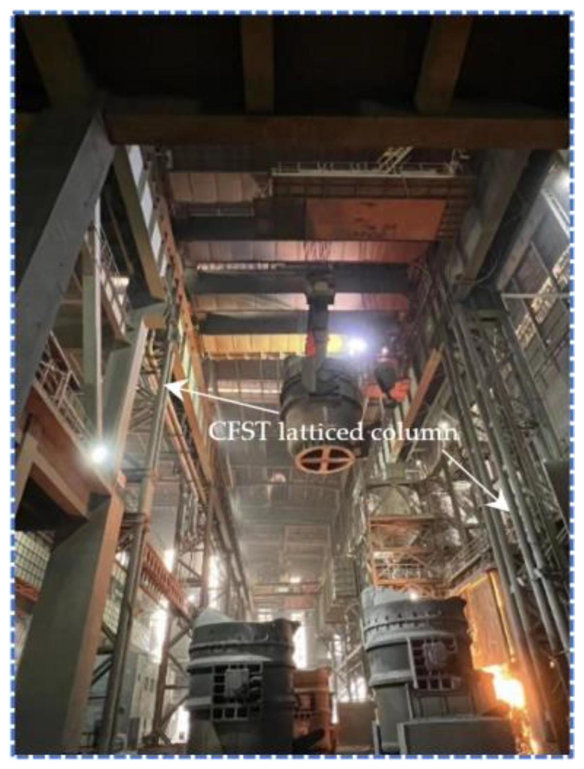
1. Introduction
2. FE Model
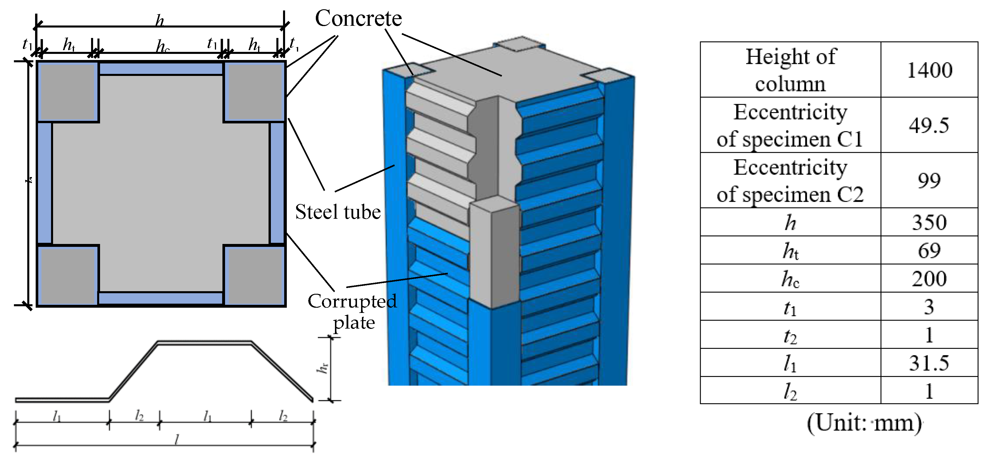
2.1. Specimen Design
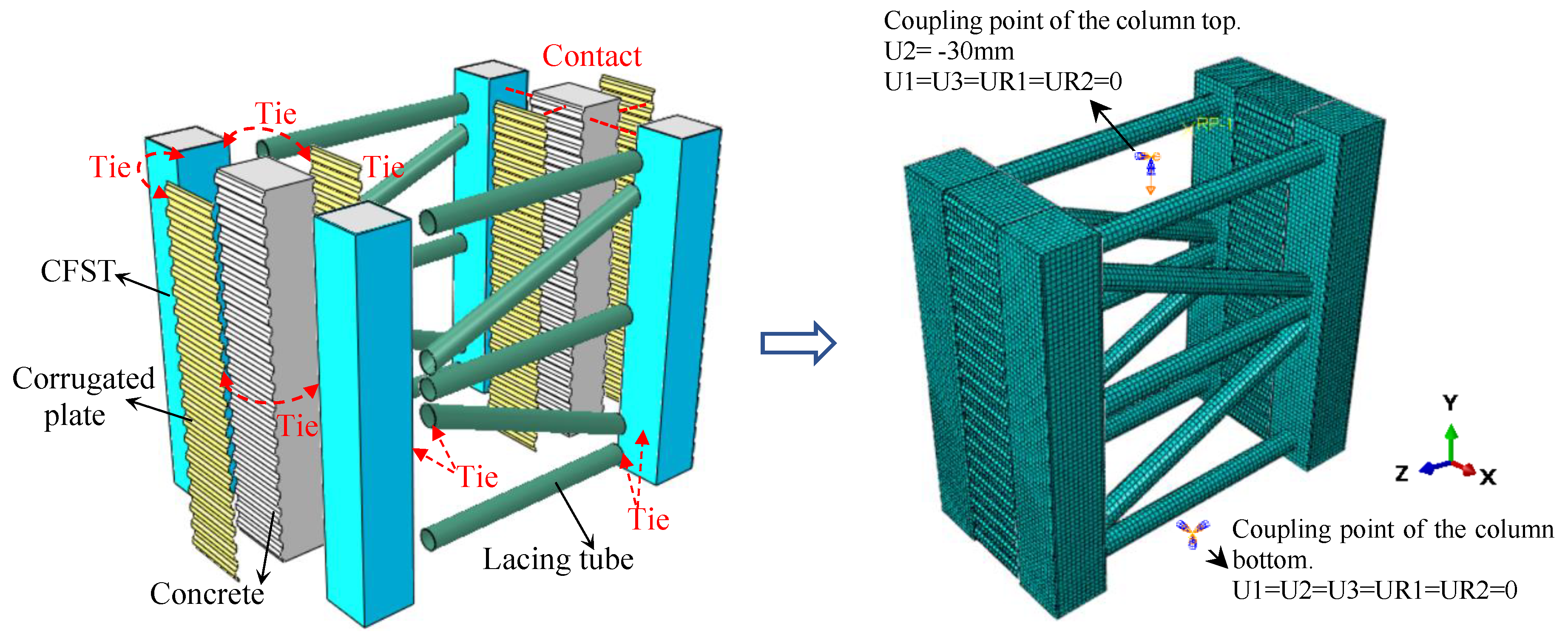
2.2. FEM Approach and Boundary Constraints
2.3. Material Constitutive Model
2.3.1. Concrete
2.3.2. Steel
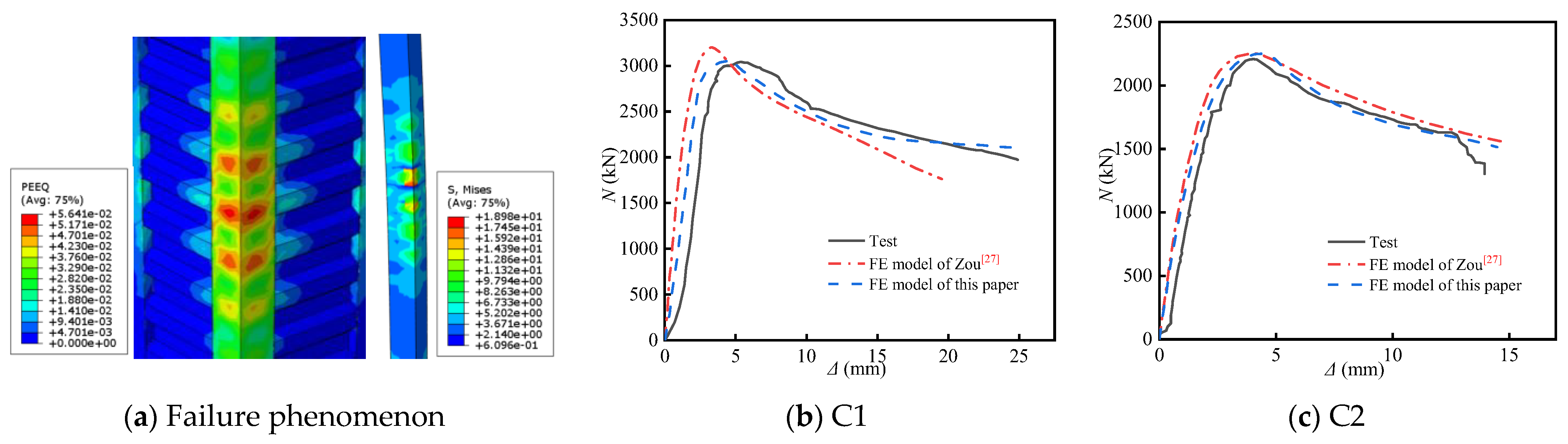
3. Validation of the FE Model
4. Simulation Results and Analytical Assessment
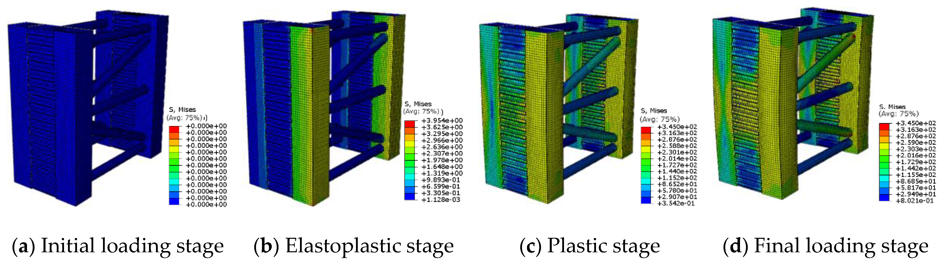
4.1. Failure Modes
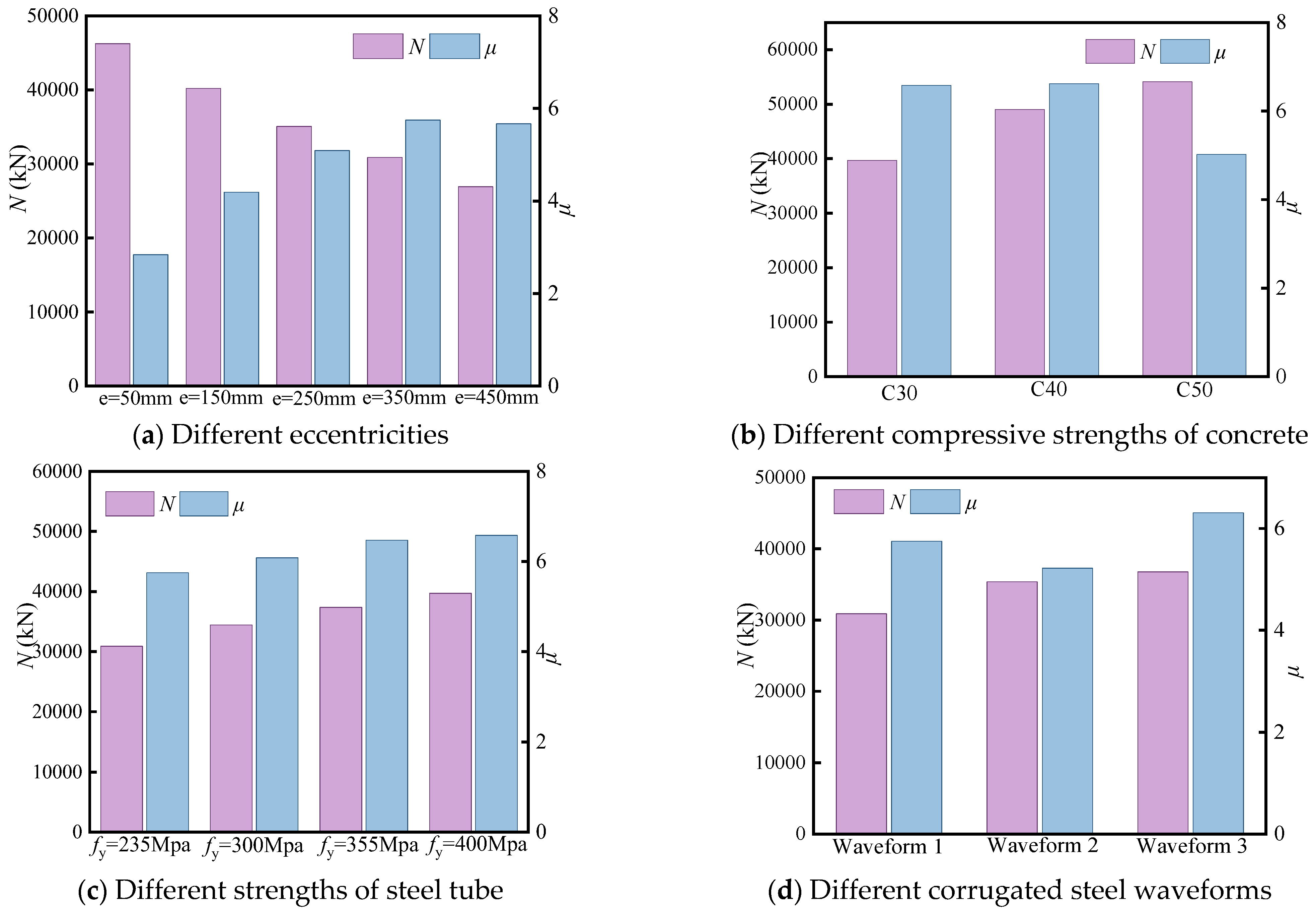
4.2. Parameter Analysis
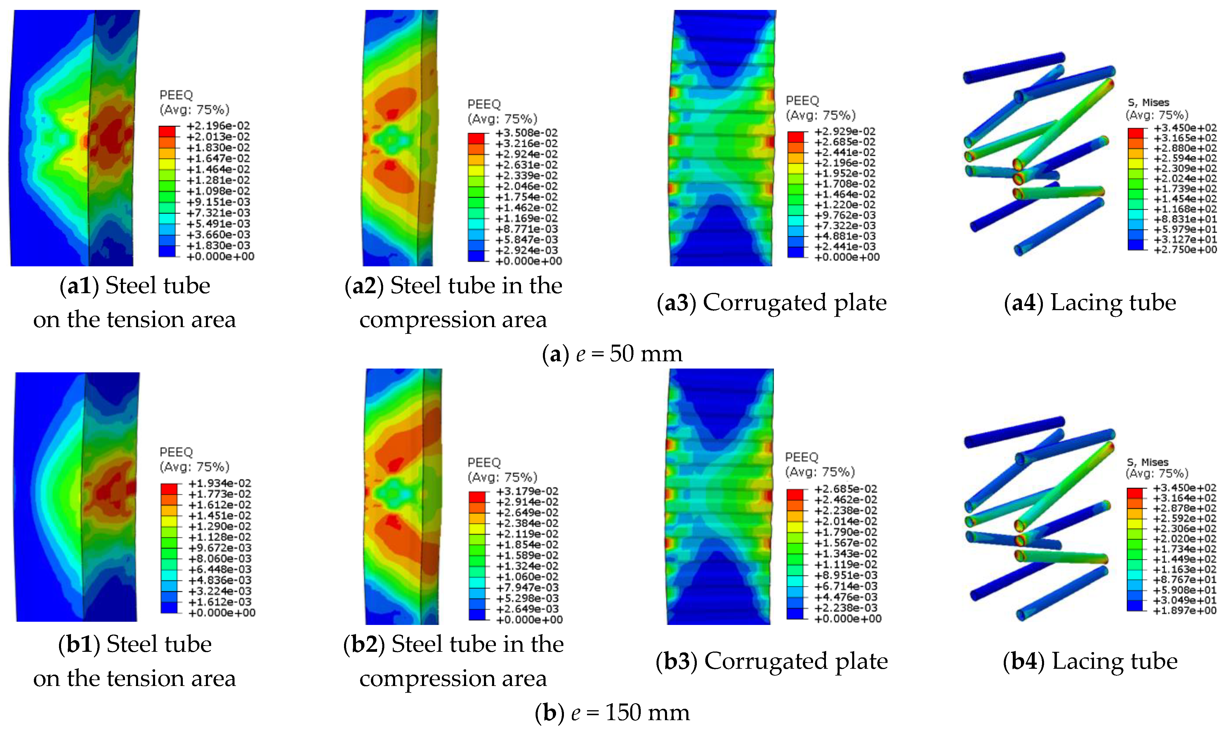
4.2.1. Eccentricity
4.2.2. Strength of Concrete
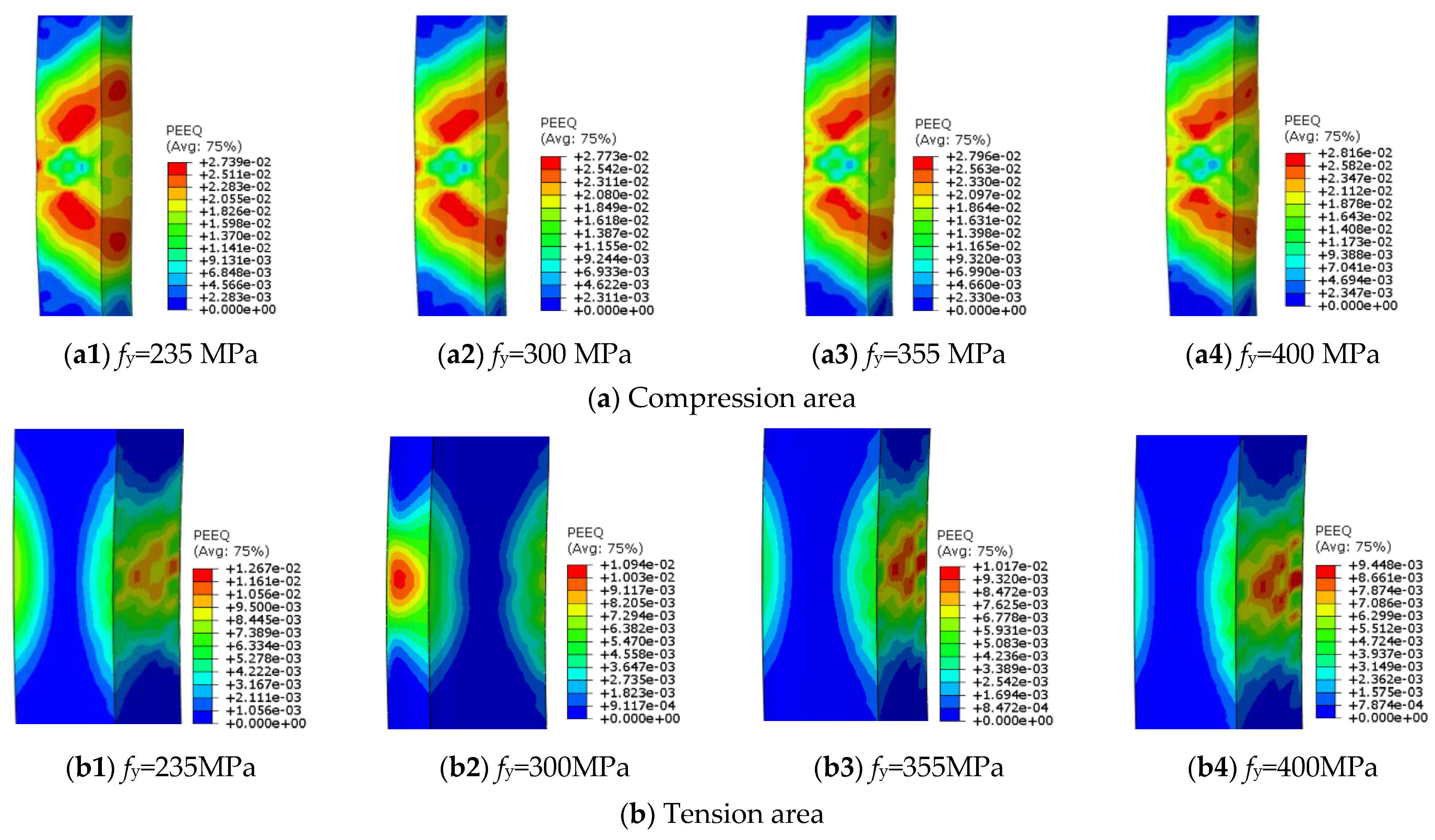
4.2.3. Strength of Steel Tube
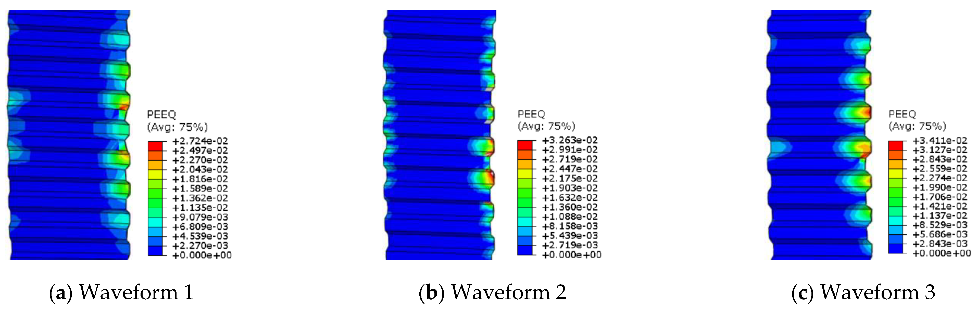
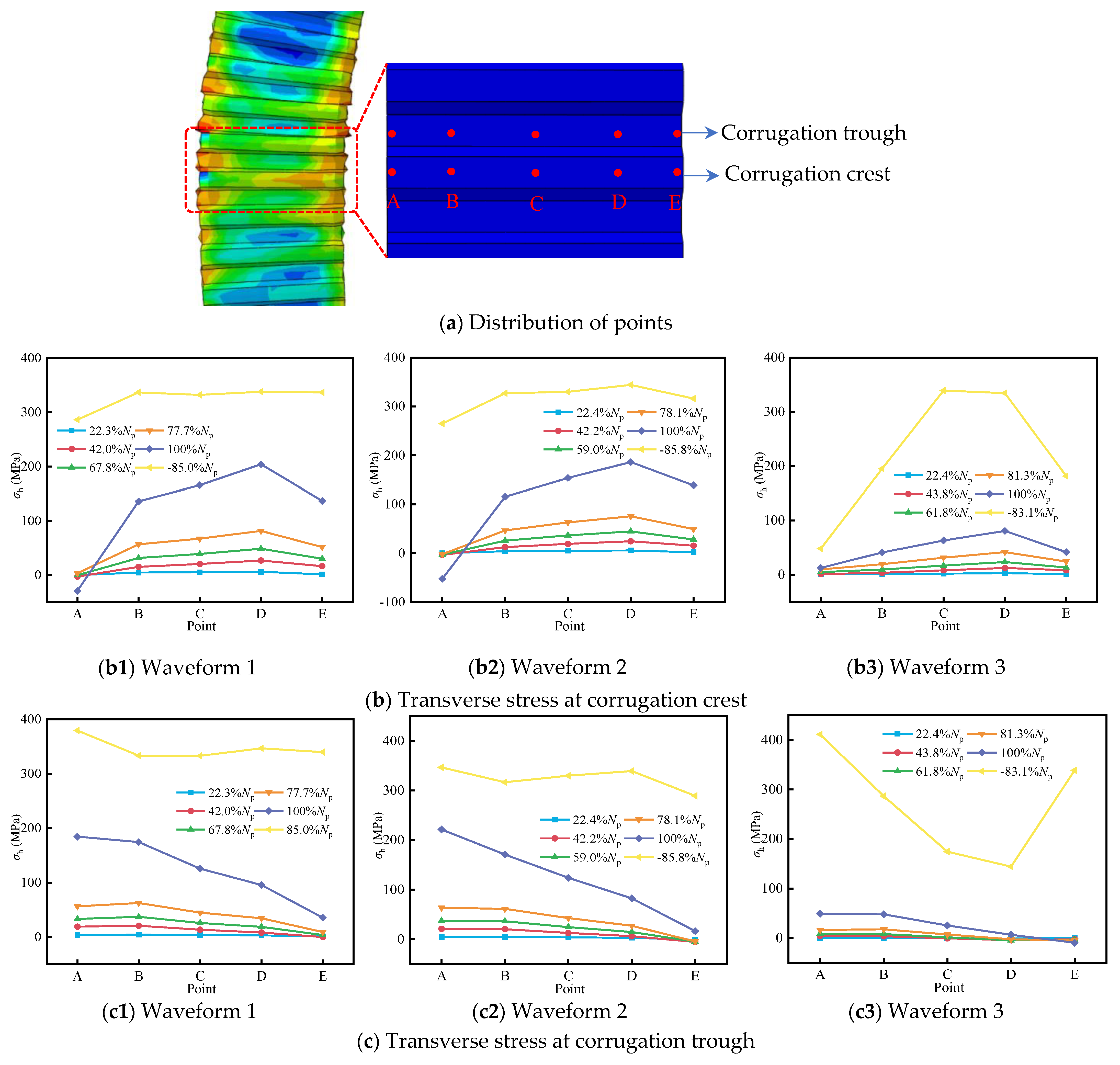
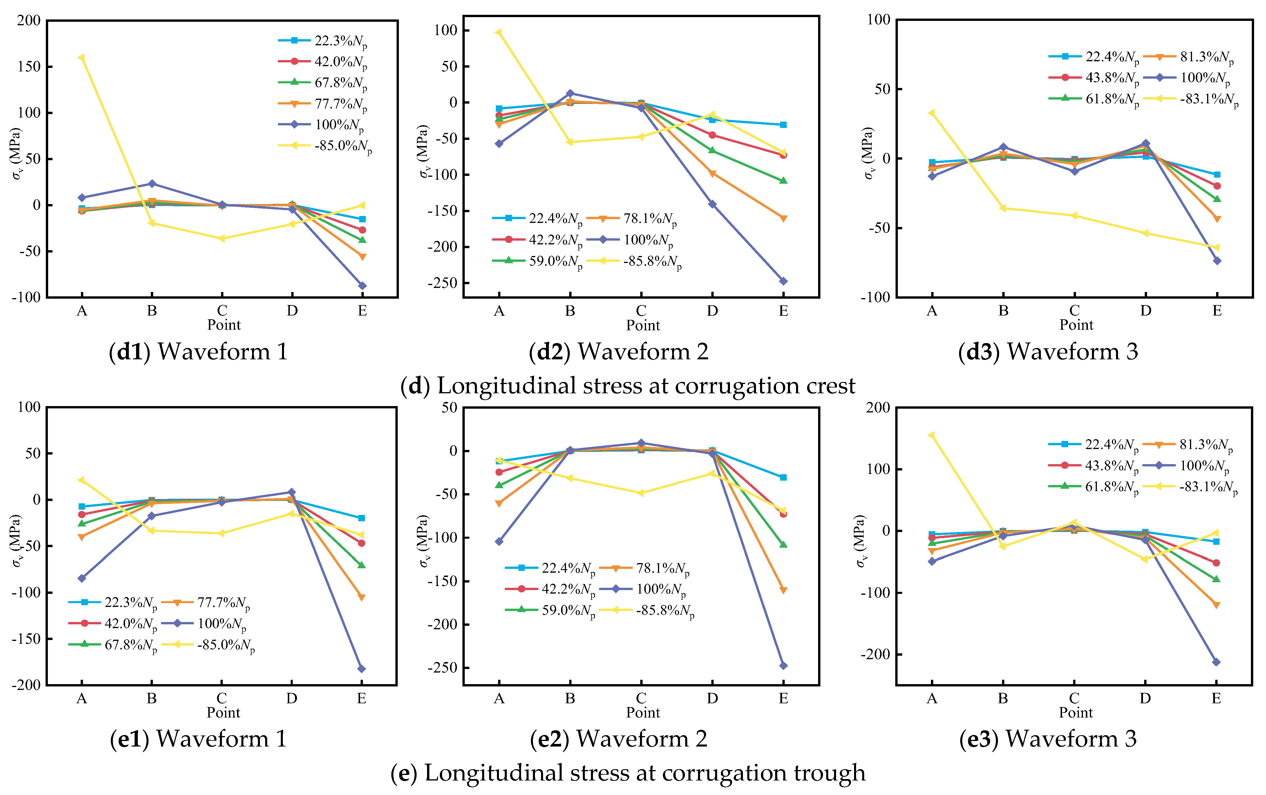
4.2.4. Waveform of Corrugated Plate
5. Bearing Capacity Calculation Method
6. Conclusions
- (1)
- Under eccentric loading, the latticed column exhibits typical bending failure characteristics, and the corrugated steel plate demonstrates a notable restraining effect under eccentric loading. The arrangement of diagonal lacing tubes optimizes the load distribution and enhances the overall bending resistance.
- (2)
- Increasing eccentricity ratios induce a pronounced bending deformation and asymmetric stress/strain distribution. The results demonstrate up to a 41.8% reduction in load capacity but a 50.6% improvement in ductility. This behavior stems from eccentric loading limiting tensile area contributions while promoting compressive stress redistribution, with ductility gains ceasing beyond 350 mm of eccentricity.
- (3)
- Higher steel strength enhances the stress redistribution in both tension and compression areas, increasing load capacity by 28.6% and ductility by 14.5%. Higher concrete strength increases the bearing capacity of the specimen, but decreases the ductility. Optimal performance requires an optimized steel–concrete composite action to achieve a better balance between load-bearing capacity and ductility.
- (4)
- The geometric configuration of corrugated steel plates significantly influences plastic strain distribution and structural performance. Waveform 3 facilitates superior stress redistribution, enhancing both the bearing capacity of the specimen by 19.1% and the ductility by 9.7%. Optimal waveform selection is therefore critical for achieving balanced improvements in load-carrying and deformation-resistant capacities.
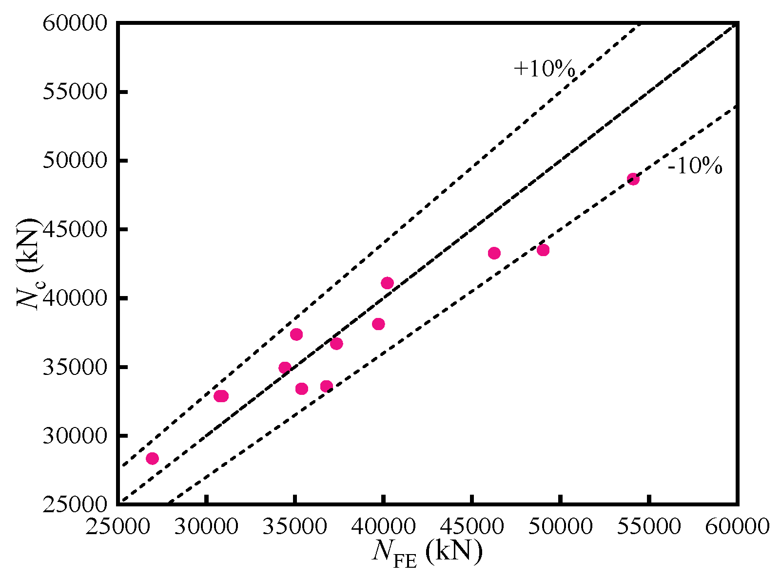
- (5)
- Based on axial capacity formulas, an eccentric compression modification term for CFST-corrugated steel plate latticed columns was proposed. Comparative analysis reveals that the proposed method maintains calculation errors within 11% of numerical simulation results, verifying its reliability for eccentric loading conditions.
Author Contributions
Funding
Data Availability Statement
Conflicts of Interest
References
- Kheyroddin, A.; Naderpour, H.; Ahmadi, M. Compressive strength of confined concrete in CCFST columns. J. Rehabil. Civ. Eng. 2014, 2-1, 106–113. [Google Scholar]
- Wei, J.G.; Han, J.P.; Luo, X.; Yang, Y.; Li, C.; Wang, W.R. Axial compression performance of ultra-high-strength concrete filled steel tubular lattice short columns. J. Constr. Steel Res. 2024, 216, 108571. [Google Scholar] [CrossRef]
- Yang, Y.F.; Liu, M.; Hou, C.; Bie, X.M. Behaviour of four-legged square CFST latticed members under lateral cyclic loading. J. Constr. Steel Res. 2019, 156, 54–74. [Google Scholar] [CrossRef]
- Zhao, X.; Zhang, N.; Hu, Z.; Li, X.; Nie, Y.; Liu, J. Axial compression behavior of novel latticed columns with CFST tubes and corrugated steel plates for industrial structures. Buildings 2025, 15, 42. [Google Scholar] [CrossRef]
- Yang, Z.M.; Chen, J. Behavior of eccentrically loaded large-scale CFST slender columns with latticed annular steel. Structures 2024, 69, 107451. [Google Scholar] [CrossRef]
- Huang, Z.; Li, X.; Chen, J.; Jiang, L.; Chen, Y.F.; Huang, Y. Research on seismic performance prediction of CFST latticed column-composite box girder joint based on machine learning. Constr. Build. Mater. 2025, 460, 139811. [Google Scholar] [CrossRef]
- Gu, C.; Wang, X.; Liu, Y.; Zhou, X.; Huang, C. Conceptual design and analysis on an innovative hybrid CFST latticed bridge pier with an RC lacing system. Structures 2025, 73, 108309. [Google Scholar] [CrossRef]
- Zeng, W.; Ayough, P.; Zhou, X.H.; Wang, Y.H.; Ren, W.; Elchalakani, M.; Elghazouli, A.Y. Performance of circular CFST columns strengthened with CFRP grid-reinforced ECC under axial compression: Numerical modelling and design. Eng. Struct. 2025, 325, 119375. [Google Scholar] [CrossRef]
- Wei, J.G.; Han, J.P.; Luo, X.; Yang, Y.; Li, C. Eccentric load capacity of ultra-high strength concrete-filled steel tubular lattice short columns. Structures 2024, 69, 107385. [Google Scholar] [CrossRef]
- Jiang, L.Z.; Zhou, W.B.; Wu, Z.Y.; Zhang, J.J. Experimental study and theoretical analysis on the ultimate load carrying capacity of four-tube concrete filled steel tubular lattice columns. China Civ. Eng. J. 2010, 43, 55–62. [Google Scholar]
- Nie, J.G.; Liao, Y.B. Experiments of four-legged concrete filled steel tubular laced columns subjected to axial loads. Tsinghua Sci. Technol. 2009, 49, 1919–1924. [Google Scholar]
- Chen, B.C.; Ou, Z.J. Experimental study on influence of slenderness ratio in concrete filled steel tubular laced columns under eccentric compression. J. Build. Struct. 2006, 27, 73–79. [Google Scholar]
- Ou, Z.J.; Chen, B.C. Experimental research on influence of eccentrically ratio on concrete filled steel tubular laced columns compressed eccentrically. J. Build. Struct. 2007, 28, 184–190. [Google Scholar]
- Liao, X.; Li, X.; Li, W.; Su, R.; Chen, M. Seismic behavior of CFST components for shear walls using double corrugated steel plates. Eng. Struct. 2025, 334, 120235. [Google Scholar] [CrossRef]
- Shi, Y.; Sun, C.; Gao, C.; Liu, J.; Peng, X. Study on lateral resistance of cold-formed corrugated steel plates with lightweight foam concrete composite walls. Thin-Walled Struct. 2025, 210, 112964. [Google Scholar] [CrossRef]
- Wu, R.M.; Tong, J.Z. Shear strength and post-ultimate behavior of multi-stiffened corrugated steel plate shear walls. J. Constr. Steel Res. 2025, 229, 109480. [Google Scholar] [CrossRef]
- Dou, C.; Xie, C.; Wang, Y.; Yang, N. Cyclic loading test and lateral resistant behavior of flat-corrugated steel plate shear walls. J. Build. Eng. 2023, 66, 105831. [Google Scholar] [CrossRef]
- Bi, Z.J.; Yang, G.T. Buckling of corrugated steel plates under uniaxial compression. J. Constr. Steel Res. 2024, 223, 109074. [Google Scholar] [CrossRef]
- Elkawas, A.A.; Hassanein, M.F.; El Hadidy, A.M.; El-Boghdadi, M.H.; Elchalakani, M. Behaviour of corrugated web girders subjected to lateral-torsional buckling: Experimental tests and numerical modelling. Structures 2021, 33, 152–168. [Google Scholar] [CrossRef]
- Shariatyazdi, P.; Ronagh, H.; Izadinia, M.; Javaheritafti, M.R. Shear buckling behavior of tapered cantilever beams with corrugated trapezoidal web under concentrated tip load. J. Constr. Steel Res. 2022, 193, 107265. [Google Scholar] [CrossRef]
- Wang, C.Y.; Yin, S.P.; Wang, B.X.; Du, J.; Ren, X.; Zhang, X. Research on the transverse flexural performance of T-PBL joints between corrugated steel webs and concrete slabs. Structures 2022, 44, 1057–1069. [Google Scholar]
- Alikhanifard, M.A.; Rahai, A.R.; Tehrani, P. A new shear strength model for steel corrugated web girders. J. Constr. Steel Res. 2022, 197, 107457. [Google Scholar] [CrossRef]
- Liu, W.; Han, L.H. Research on some issues of ABAQUS analysis on the behavior of axially loaded concrete-filled steel tubes. J. Harbin Inst. Technol. 2005, 37, 157–160. [Google Scholar]
- Esmaeily, A.; Xiao, Y. Behavior of reinforced concrete columns under variable axial loads: Analysis. ACI Struct. J. 2005, 102, 736–744. [Google Scholar]
- Yu, H.L.; Jeong, D.Y. Application of a stress triaxiality dependent fracture criterion in the finite element analysis of unnotched Charpy specimens. Theor. Appl. Fract. Mech. 2010, 54, 54–62. [Google Scholar] [CrossRef]
- Bao, Y.B.; Wierzbicki, T. On fracture locus in the equivalent strain and stress triaxiality space. Int. J. Mech. Sci. 2004, 46, 81–98. [Google Scholar] [CrossRef]
- Zhang, S.J.; Zou, Y.; Wang, C.Q.; Wu, Y.C.; Chen, M. Behaviour and bearing capacity of concrete-filled horizontal corrugated steel plate-tubular composite columns under biaxial eccentric compression. Eng. Mech. 2021, 38, 81–90. [Google Scholar]
- Su, R.; Li, X.; Chen, M.; Yan, H.; Wu, Y.C. Confinement mechanism of angle steel-corrugated steel plate confined concrete columns under compression. J. Constr. Steel Res. 2025, 230, 109547. [Google Scholar] [CrossRef]
- Sun, Z.X. Study on Axial Compression Behavior and Confinement Mechanism of Steel Tubular-Corrugated Steel Plate Concrete Columns. Master’s Thesis, Jiangnan University, Wuxi, China, 2023. [Google Scholar]


| № | Specimen | Strength of Steel Tube fsy (MPa) | Strength of Concrete fc (MPa) | Eccentricity e (mm) | Thickness of Lacing Tube tl (mm) | Strength of Lacing Tube fL (MPa) | Waveform of Corrugated Plate |
|---|---|---|---|---|---|---|---|
| 1 | T1 | 235 | 30 | 350 | 6 | 345 | Waveform 1 |
| 2 | E1 | 235 | 30 | 150 | 6 | 345 | waveform 1 |
| 3 | E2 | 235 | 30 | 250 | 6 | 345 | waveform 1 |
| 4 | E3 | 235 | 30 | 450 | 6 | 345 | waveform 1 |
| 5 | C1 | 400 | 40 | 350 | 6 | 345 | waveform 1 |
| 6 | C2 | 400 | 50 | 350 | 6 | 345 | waveform 1 |
| 7 | H1 | 300 | 30 | 350 | 6 | 345 | waveform 1 |
| 8 | H2 | 355 | 30 | 350 | 6 | 345 | waveform 1 |
| 9 | H3 | 400 | 30 | 350 | 6 | 345 | waveform 1 |
| 10 | B1 | 355 | 30 | 350 | 6 | 345 | waveform 2 |
| 11 | B2 | 355 | 30 | 350 | 6 | 345 | waveform 3 |
| 12 | LQ1 | 235 | 30 | 350 | 6 | 235 | waveform 1 |
| 13 | LQ2 | 235 | 30 | 350 | 6 | 345 | waveform 1 |
| 14 | LQ3 | 235 | 30 | 350 | 6 | 400 | waveform 1 |
| Steel Tube Bs × ts (mm) | Corrugated Plate Width Bc (mm) | Corrugated Plate Thickness tc (mm) | Lacing Tube Diameter D (mm) | Lacing Tube Thickness tL (mm) | |
|---|---|---|---|---|---|
| T1 | □450 × 12 | 600 | 1.2 | 180 | 6 |
| Specimen | Eccentricity e (mm) | Strength of Steel Tube fsy (MPa) | Strength of Concrete fc (MPa) | Thickness of Lacing Tubes tl (mm) | Strength of Steel Tube fL (MPa) | NP (kN) | μ |
|---|---|---|---|---|---|---|---|
| T1 | 350 | 235 | 30 | 6 | 345 | 30,892.8 | 5.75 |
| E1 | 50 | 235 | 30 | 6 | 345 | 46,259.9 | 2.84 |
| E2 | 150 | 235 | 30 | 6 | 345 | 40,224.3 | 4.19 |
| E3 | 250 | 235 | 30 | 6 | 345 | 35,089.1 | 5.09 |
| E4 | 450 | 235 | 30 | 6 | 345 | 26,942.5 | 5.67 |
| C1 | 350 | 400 | 40 | 6 | 345 | 49,030.7 | 6.62 |
| C2 | 350 | 400 | 50 | 6 | 345 | 54,117.7 | 5.02 |
| H1 | 350 | 300 | 30 | 6 | 345 | 34,442.3 | 6.08 |
| H2 | 350 | 355 | 30 | 6 | 345 | 37,349.8 | 6.47 |
| H3 | 350 | 400 | 30 | 6 | 345 | 39,718.9 | 6.58 |
| B1 | 350 | 235 | 30 | 6 | 345 | 35,379.9 | 5.22 |
| B2 | 350 | 235 | 30 | 6 | 345 | 36,788.9 | 6.31 |
| LQ1 | 350 | 235 | 30 | 6 | 235 | 30,771.4 | 5.73 |
| LQ2 | 350 | 235 | 30 | 6 | 300 | 30,771.5 | 5.75 |
| LQ3 | 350 | 235 | 30 | 6 | 400 | 30,771.5 | 5.76 |
| № | Specimen | Nc (kN) | NFE (kN) | Nc/Np |
|---|---|---|---|---|
| 1 | T1 | 32,876.62 | 30,892.8 | 1.06 |
| 2 | E1 | 43,266.76 | 46,259.9 | 0.94 |
| 3 | E2 | 41,101.83 | 40,224.3 | 1.02 |
| 4 | E3 | 37,362.80 | 35,089.1 | 1.06 |
| 5 | E4 | 28,339.61 | 26,942.5 | 1.05 |
| 6 | C1 | 43,497.79 | 49,030.7 | 0.89 |
| 7 | C2 | 48,657.56 | 54,117.7 | 0.90 |
| 8 | H1 | 34,939.73 | 34,442.3 | 1.01 |
| 9 | H2 | 36,685.44 | 37,349.8 | 0.98 |
| 10 | H3 | 38,113.75 | 39,718.9 | 0.96 |
| 11 | B1 | 33,409.89 | 35,379.9 | 0.94 |
| 12 | B2 | 33,587.90 | 36,788.9 | 0.91 |
| 13 | LQ1 | 32,876.62 | 30,771.4 | 1.07 |
| 14 | LQ2 | 32,876.62 | 30,771.5 | 1.07 |
| 15 | LQ3 | 32,876.62 | 30,771.5 | 1.07 |
Disclaimer/Publisher’s Note: The statements, opinions and data contained in all publications are solely those of the individual author(s) and contributor(s) and not of MDPI and/or the editor(s). MDPI and/or the editor(s) disclaim responsibility for any injury to people or property resulting from any ideas, methods, instructions or products referred to in the content. |
© 2025 by the authors. Licensee MDPI, Basel, Switzerland. This article is an open access article distributed under the terms and conditions of the Creative Commons Attribution (CC BY) license (https://creativecommons.org/licenses/by/4.0/).
Share and Cite
Xiao, X.-W.; Zhang, N.-N.; Zhao, X.; Liu, J.; Hu, Z.-H.; Li, X. Behavior of Eccentrically Loaded Concrete-Filled Steel Tube Latticed Columns with Corrugated Steel Plates for Industrial Structures. Buildings 2025, 15, 1788. https://doi.org/10.3390/buildings15111788
Xiao X-W, Zhang N-N, Zhao X, Liu J, Hu Z-H, Li X. Behavior of Eccentrically Loaded Concrete-Filled Steel Tube Latticed Columns with Corrugated Steel Plates for Industrial Structures. Buildings. 2025; 15(11):1788. https://doi.org/10.3390/buildings15111788
Chicago/Turabian StyleXiao, Xue-Wen, Ning-Ning Zhang, Xuan Zhao, Jun Liu, Zhao-Hui Hu, and Xian Li. 2025. "Behavior of Eccentrically Loaded Concrete-Filled Steel Tube Latticed Columns with Corrugated Steel Plates for Industrial Structures" Buildings 15, no. 11: 1788. https://doi.org/10.3390/buildings15111788
APA StyleXiao, X.-W., Zhang, N.-N., Zhao, X., Liu, J., Hu, Z.-H., & Li, X. (2025). Behavior of Eccentrically Loaded Concrete-Filled Steel Tube Latticed Columns with Corrugated Steel Plates for Industrial Structures. Buildings, 15(11), 1788. https://doi.org/10.3390/buildings15111788