Article

Comparative Study of Structural and Quality Controls for Grouted Sleeve Connections in Different Standards: Connection Technology, Design, and Mechanical Requirements

Institute of Civil Engineering and Architecture, Ural Federal University, Mira 17, Yekaterinburg 620062, Russia
*
Author to whom correspondence should be addressed.
Buildings 2025, 15(11), 1768; https://doi.org/10.3390/buildings15111768
Submission received: 21 April 2025 / Revised: 18 May 2025 / Accepted: 20 May 2025 / Published: 22 May 2025
(This article belongs to the Section Building Structures)

Abstract

:
As one type of critical load-bearing element in precast concrete structures, grouted sleeve (GS) connections enable efficient force transmission between reinforcing bars while maintaining structural integrity. Despite their growing global adoption, significant variations exist in design philosophies, construction specifications, and performance requirements among regional standards. Through bibliometric analysis, the most active countries and regions in GS application and research worldwide were identified, and the relevant technical standards established by these countries and regions were systematically reviewed. By comparing standards from Asia, the Americas, Europe, and Oceania, the main differences in design philosophy, construction quality control, material specifications, and performance requirements among these standards were analyzed and identified. The results show that different standards have a conceptual difference at the materials and quality control level, with one approach focusing on stricter management of sleeve materials and more detailed on-site construction requirements, and another approach emphasizing testing-based methods and third-party verification. These standards can be divided into the following two categories for the design limits of GS tensile performance: one category takes multiples of the yield strength of the connected reinforcing bars as the limit, and the other category takes multiples of the tensile strength of the connected reinforcing bars as the limit. Regarding mechanical performance requirements, standards using the ultimate tensile strength of the connected reinforcing bars as the control parameter differ from those using multiples of yield strength in their performance requirements for connections of low-strength and high-strength reinforcing bars. The variation in yield-to-tensile strength ratios among steel grades across different countries is a key factor leading to these different requirements. When using the uniform steel bar material properties specified in the standard for quantification, as the bar strength increases from approximately 240 MPa to 600 MPa, the minimum required ratio of the limits for standards based on multiples of yield strength and multiples of tensile strength increases from 0.79 to 1.07. When applying GS connections to reinforcing bars of varying strength levels, using fixed strength multiplier requirements may result in uneconomical designs or create technical challenges in achieving the required strength.

1. Introduction

In building structures, the overall mechanical performance of members depends not only on cross-sectional dimensions and material properties but also on the technical details of structural connections. Compared with traditional cast-in-place reinforced concrete structures, precast reinforced concrete and precast–cast-in-place composite structures feature joints between precast components, resulting in different damage characteristics and failure mechanisms. These connection regions are relatively weak zones, where local cracking tends to occur prematurely under cyclic loading [1]. Insufficient joint strength may lead to early structural failure [2]. One crucial factor that determines the mechanical performance of precast component connections is the reliability of bar splicing, as the bond performance of reinforcing bars significantly affects both the connection and the overall member performance [3]. Adequate bond strength boosts the load capacity and deformation capacity of structures subjected to seismic or static conditions [4,5].
Grouted sleeve (GS) connections are widely used in precast reinforced concrete structures to provide quick, cost-effective, and reliable bar splicing [6]. As shown schematically in Figure 1, a GS connection is formed by an interplay of three main components: the sleeve, the grouting material, and the reinforcing bars. During on-site installation, the protruding bars of adjacent precast members are inserted into each end of the sleeve. Grouting material is subsequently pumped in through an injection port until it flows out of the vent hole. After the grout sets and hardens, the GS connection transmits tension and compression between the adjacent bars via a combination of bond action and confinement [7,8]. This is achieved by the anti-bond-slip capacity of the grout and the mechanical gripping effect of the rebar ribs [8,9]. Consequently, structural continuity is maintained as the connection transfers load through continuous stress redistribution. The tensile load induces shear stress at the bar–grout interface, which in turn generates hoop strain in the grout. The sleeve’s rigidity restrains this strain and provides a degree of confinement pressure that enhances friction at the grout interface, effectively preventing slippage [9,10]. Although placing GS connections within the plastic hinge zone of beams or columns can lead to slightly reduced displacement ductility and ultimate deformation capacity [10,11], studies have demonstrated that beams, columns, and walls using GS connections can achieve stiffness, yield strength, and ultimate strength capacity comparable to—or sometimes even matching—those of monolithic cast-in-place counterparts [6,7,12,13,14]. Furthermore, in experiments by Jia et al. [15], prefabricated frame–shear wall structures using GS connections showed a 143% increase in ductility and a 29.8% improvement in energy dissipation compared to traditional cast-in-place frame–shear wall specimens.
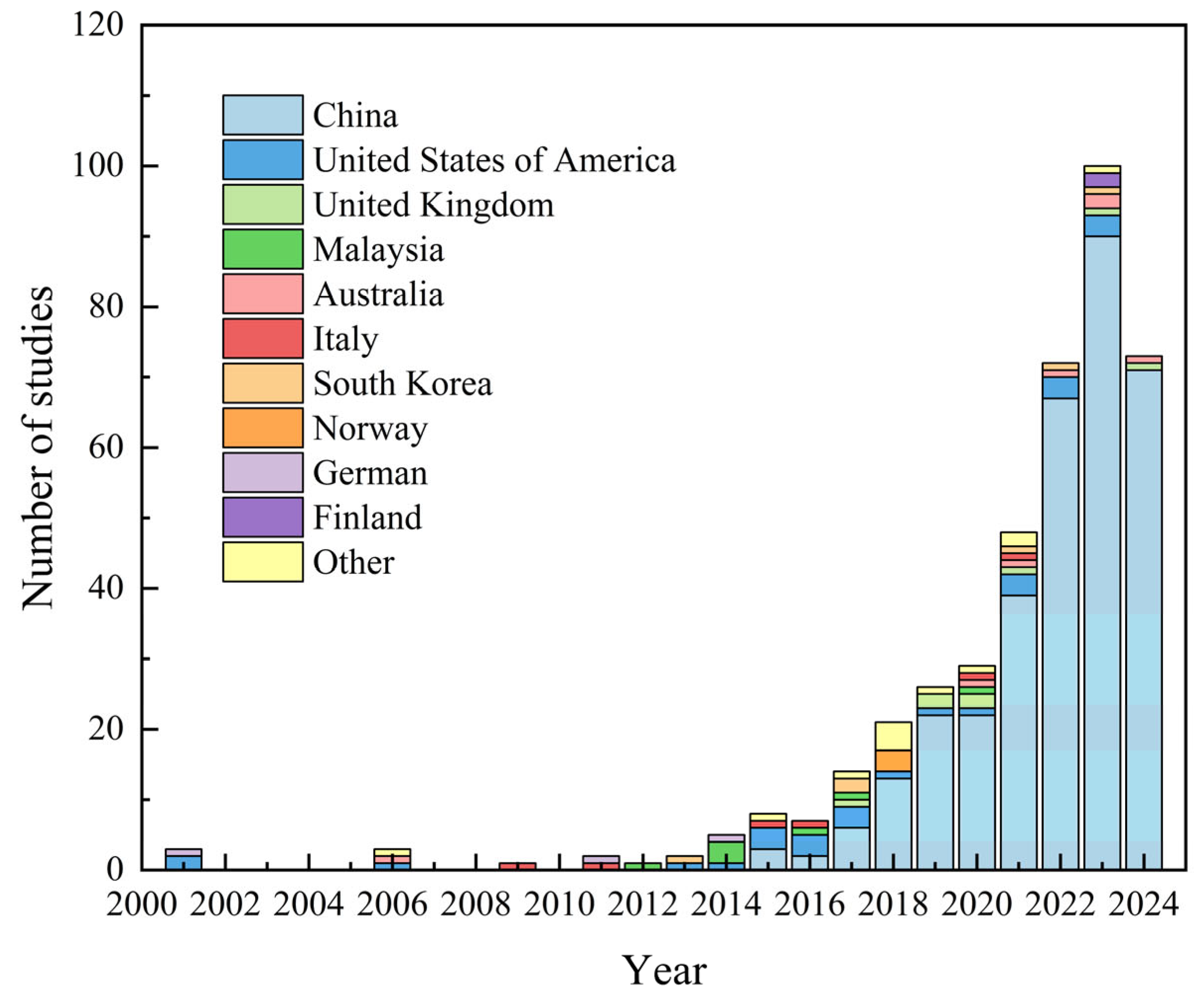
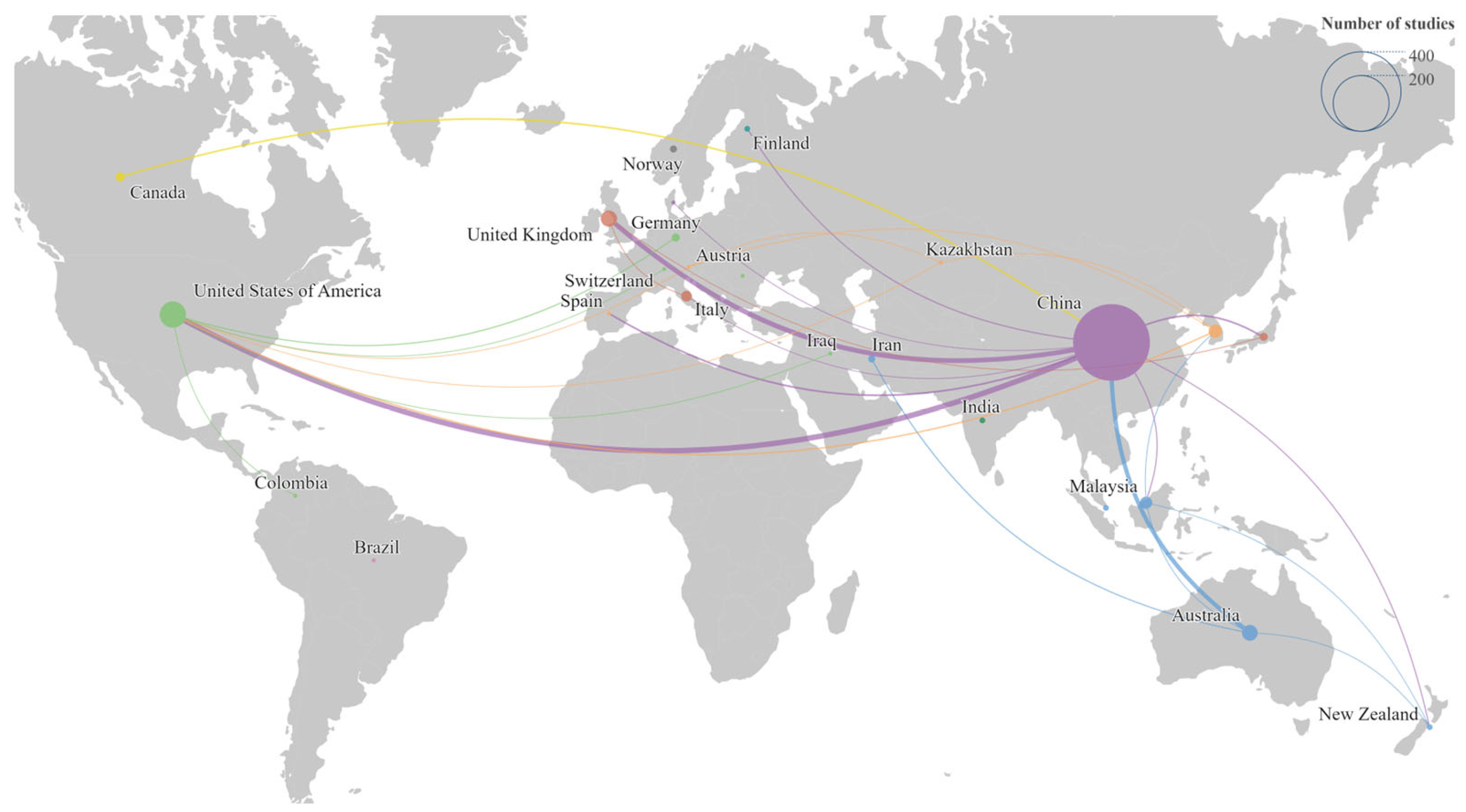
A search on the Web of Science Core Collection database for publications related to GS connections reveals the quantitative growth trend shown in Figure 2 and the international collaboration network illustrated in Figure 3. Due to the construction practice of manufacturing structural elements in factories and assembling them on-site, along with the desirable mechanical performance offered by GS connections, GS technology has found increasing use in precast reinforced concrete buildings in recent years. As shown in Figure 2 and Figure 3, most publications on GS connections originate from China, the United States, the United Kingdom, Australia, and Italy, and these research activities continue to gain momentum. China serves as a central hub in the GS research network, contributing the largest number of studies and collaborating with the highest number of countries. The United States and the United Kingdom rank second and third, respectively, in terms of research output, and China’s collaborative strength with both these countries ranks first and second among all international partnerships. Overall, the publication network on GS connections extends across North America (the United States and Canada), South America (Brazil and Colombia), Europe (the United Kingdom, Germany, Switzerland, etc.), Asia (India, Iran, Malaysia, etc.), and Oceania (Australia and New Zealand). These patterns suggest that national and regional standards, as well as engineering practices for GS connections, may exhibit substantial divergences or complementary features in different parts of the world.
In prior research, it has been shown that rebar anchorage length, grout strength, sleeve material properties, sleeve geometry, and rebar parameters are the main design factors influencing the mechanical performance and bond strength of GS connections. In Sun’s study [7], pullout tests were conducted on 72 GS specimens configured with various parameters, quantifying the effects of grout strength, rebar anchorage length, sleeve materials, and rebar diameter on connection performance. A formula for calculating the anchorage length in grouted sleeve connections was also proposed. Song et al. [16] designed specimens with different grout materials, bar diameters, anchorage lengths, and eccentricities, then performed uniaxial tensile tests to compare and analyze how these design parameters affect the mechanical performance of GS connections. Guo et al. [17] evaluated the mechanical behavior of rebar in grouted sleeve connections under tensile loads for different grout strengths and compared the measured parameters with standard values. Lu et al. [10] investigated the mechanical behavior of wedge-type GS and wedge-plus-thread GS under uniaxial tension, examining how rebar anchorage length, diameter, and wedge or threaded sleeve designs affect connection performance. Ling et al. [18] designed five different specimens using conical sleeves in precast wall panels to study the load-bearing capacity, ductility, failure modes, and horizontal displacement of GS connections under lateral loading, focusing on the influences of anchorage length and sleeve diameter.

Research Purpose

During structural design and practice, variations in design philosophies, safety requirements, material properties, and adopted analytical models lead to differences in national or regional standards for GS connection parameters and construction requirements. In response, the present study pursues the following five interconnected purposes:
(1)
Identify the most active countries/regions in GS research through bibliometric analysis and compile the full set of standards, codes, or guidelines they currently adopt.
(2)
Investigate and compare, for those key countries or regions, the provisions of their standards or guidelines with respect to design basis, applicability limits, material specifications, geometric constraints, construction and inspection procedures, and acceptance criteria.
(3)
For representative reinforcing-steel grades, quantitatively evaluate the minimum tensile capacity, ductility, slip limit, and anchorage length required by each standard, and assess how these prescriptions influence structural design outcomes and economy.
(4)
Link the observed discrepancies to underlying factors such as yield-to-tensile strength ratios, seismic hazard levels, and manufacturing practices, thereby clarifying the technical mechanisms behind different code philosophies.
(5)
Propose design recommendations to support future code revisions and promote the safe, economical, and sustainable application of GS connections worldwide.

2. Materials and Methods

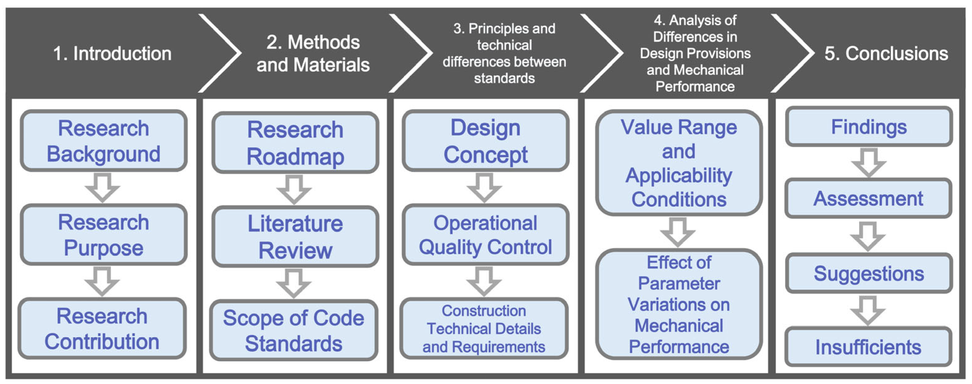
Figure 4 presents the research roadmap, illustrating the overall structure and methodology of this study. Section 1 provided an introduction to the research background, objectives, and contributions. The current section (Section 2) details this study’s organization, research approach, and methods. Through a literature review, preliminary determinations have been made regarding the key parameters and design requirements for GS connections that necessitate focused analysis; these parameters are then used to define the scope of the standards under scrutiny and the basic information required.
Section 3 examines the differences in design philosophies among various national or regional standards related to GS connections, as well as the variations in construction technologies and requirements outlined in these standards. Section 4 introduces the principal design provisions, value ranges, and applicability conditions for GS connections in the selected standards, highlighting how they differ across regions. From the perspectives of anchorage length, grout strength, bar diameter, and sleeve geometry, the factors influencing the mechanical performance of GS connections are explored, and the differences in load-bearing capacity, ductility, and construction efficiency across standards are evaluated. Finally, Section 5 summarizes the findings, and—based on the experimental evidence and standard comparison—offers suggestions for GS connection design, construction, and future standard revisions.
In the majority of publications on GS-related experimental research, it is typically stated that the specimen design and parameters satisfy local or international standard requirements. For example, Zhang et al. [19] performed static tensile tests on fully grouted sleeve connections and on single bars at elevated temperatures. They highlighted that the tensile strength of the high-grade carbon steel sleeve (at 615 MPa) fully meets the requirements of JG/T 398 [20], while the compressive strength and longitudinal expansion rate of the cement-based grout adhere to JG/T 408 [21]. The overall mechanical performance of the connection was subsequently evaluated in accordance with ACI 318 [22] and JGJ 355 [23]. Likewise, Lu et al. examined the mechanical behavior of two types of low-cost GS sleeves manufactured from seamless steel tubes through uniaxial tensile tests, investigating the effects of embedment length, bar diameter, and wedge length on connection performance; the tensile capacity and ductility of both sleeves conformed to the requirements of ACI 318 [22] and JGJ 107 [24], while the grout properties met the testing requirements of JG/T 408 [21].
Wu et al. [25] investigated the mechanical performance and failure modes of GS connections under uniaxial tension and large-deformation cyclic tensile–compressive loads at varying degrees of grout compaction. Their specimen sleeves were produced in compliance with JG/T 398 [20], and fluidity, compressive strength, and vertical expansion rate tests for the grout were performed according to JG/T 408 [21]. In the study by Bing and Yuan [26] on bond performance between rebar and grout and the sleeve confinement effect in grouted sleeve connections, four existing standards were briefly discussed—Fib Model Code [27], GB 50010-2010 [28], ACI 318-19 [22], and Australian Standard 3600 [29]—and a multi-factor bond strength prediction model suitable for GS connections was proposed, considering confinement stress, grout strength, and rebar parameters.
In their low-cycle fatigue tests involving repeated inelastic deformation on 11 mechanically spliced connectors widely used in the U.S. market, Sharma et al. [30] reported that, although ACI 318-19 [22] permits Grade 60 rebar Type 1 and Type 2 couplers in plastic hinge zones, it specifically prohibits mechanical splices for Grade 80 and higher rebar in regions susceptible to large cyclic strains, due to concerns over their behavior. Seifi et al. [31] surveyed details of panel connections and their seismic performance in existing precast concrete buildings in New Zealand, discovering that most connections only meet the minimum requirements of the New Zealand concrete design standard NZS 3101:2006 [32]. They noted practical issues in standard implementation, including mismatched bar spacing for metal conduit connections and panel reinforcement, leading to suboptimal splicing efficiency.
Ferreira et al. [13], following the requirements of the Brazilian standard ABNT NBR 9062:2017 [33], compared the deflection, rotational stiffness, and crack distribution of precast columns using GS connections with cast-in-place columns in four-point bending tests. Their results indicated that although the precast column joint exhibited minor localized rotation, the overall deformation curve closely matched that of the cast-in-place columns, with a difference of less than 10%. This meets the standard-prescribed criterion for “equivalent integral stiffness” (fixing factor α R     0 .85), thereby verifying that GS connections can approximate cast-in-place column behavior under service limit states.
Ye and Lu [34] proposed a bond behavior model that accounts for sleeve confinement, comparing multiple international standard requirements in their study. They noted that ACI 318-19 [22] mandates that connector tensile strength must be at least 1.25 times the yield strength of the bar, whereas Chinese standard JG/T 398-2019 [20] requires an anchorage length ≥8 times the bar diameter, and Eurocode 2 (EN 1992-1-1) [35] stipulates an anchorage length ≥10 times the bar diameter. Ghayeb et al. [36] fabricated short-threaded GS and long-grouted GS specimens in accordance with ISO 15835, conducting uniaxial tension tests to evaluate the mechanical properties of the spliced bars; they analyzed the influence of embedment length and rebar eccentricity and proposed a predictive bond strength model based on British Standard BS 8110 [37].
It is evident that the degree of standardization of GS connections varies across national standards. Correspondingly, the design, construction, and testing requirements underpinning GS connections differ by country, encompassing different categories of regulations. Notable differences exist in design principles, material requirements (including sleeve and grout characteristics), sleeve dimensions, acceptance criteria, and construction parameters. By compiling the main standards for GS connections from key countries in North America, South America, Asia, Europe, and Oceania—i.e., those shown in the publication network in Figure 3 as principal contributors to research output and international collaboration—Table 1 presents a summary of the relevant national or regional GS standards. These standards form the scope of the comparative analysis in this paper.

3. Principles and Technical Differences Between Standards

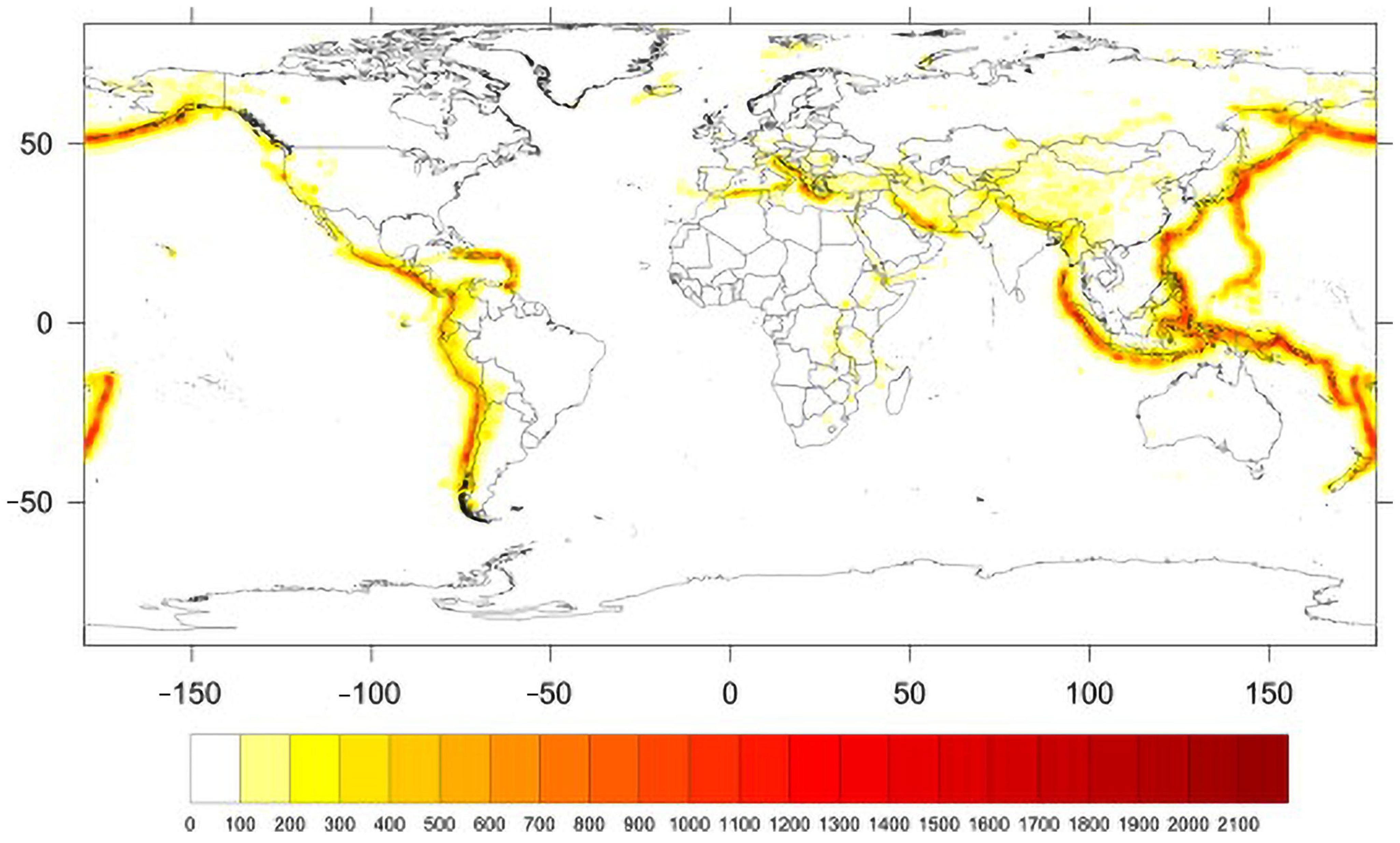
In general, national standards must account for local environmental conditions—such as extreme temperatures, seismicity, rainfall, and wind loads—causing fundamental differences in design principles and writing approaches. For example, in a study on global seismic hazards and risks, Ordaz et al. [46] performed a globally consistent probabilistic assessment using the NEIC–USGS earthquake catalog, a smoothed seismicity model, tectonic zoning, and ground-motion prediction equations, thereby generating results such as those shown in Figure 5. The color scale in this figure indicates peak ground acceleration (PGA, in cm/s2) corresponding to a 475-year return period—or equivalently, a 10% chance of exceedance in 50 years. Red-hued areas, such as the Circum-Pacific Seismic Belt, the Japanese Archipelago, the Andes, and the Himalayas, exhibit the highest seismic hazard; in contrast, stable continental interiors like the African cratons, northern Europe, and Siberia display significantly lower hazard (lighter shades). Notably, China, the United States, and Brazil each include certain regions with considerable seismic risk, particularly in western and southwestern China. Meanwhile, in Australia and northern Europe, seismic risk is very low, with PGA values rarely exceeding 100 cm/s2.
Since seismic hazards manifest regionally diverse spatial distributions worldwide, the safety factors, material strength reduction factors, and detailing requirements set forth in different national or regional standards vary accordingly. Similar distinctions also arise in the design of other environmental loads—taking wind loads as another example, Kwon and Kareem [47] compared eight major international wind-load standards and found that the primary cause of wind-load differences lies in assumptions relating to the wind-speed profile and turbulence parameters. While the along-wind responses among the standards are relatively consistent, cross-wind and torsional responses demonstrate distinctly higher scatter due to the complexity of wake flow effects.

3.1. Design Concept

International mainstream structural design currently adopts a probability-based Limit State Design approach—also referred to as Load and Resistance Factor Design (LRFD). In this framework, various failure or serviceability loss scenarios of a structure are classified into multiple “limit states” for analysis, using partial safety factors to distinguish different load types and associated uncertainties, as well as to incorporate specific material strengths and component safety factors. All structural design standards within the scope of this paper employ LRFD with Ultimate Limit States (ULSs) and Serviceability Limit States (SLSs). ULS requirements ensure that no overall or local failure occurs under the most adverse load combinations, while SLS primarily addresses deflection, crack width, and vibration requirements under normal operation.
Discrepancies among standards often arise from variations in partial safety factors, environmental load weightings, construction technical requirements, and prescribed detailing measures. Specifically, load partial factors and material resistance or reduction factors may differ, based on historical data, environmental surveys, and statistical analyses. Countries or regions exhibiting significant variations in environmental conditions—such as earthquakes, hurricanes, or severe winters—tend to adopt distinct environmental load standards, yielding different load combination patterns and partial safety factors. In addition, under LRFD principles, different standards may incorporate detailed mandatory guidelines for structural detailing.
At present, China has published separate, dedicated regulatory documents for GS connections, including JGT-398-2019 [20], JG/T 408-2019 [21], and JGJ 355-2015 [23], establishing standards for GS as a type of steel bar connector. However, the United States, Australia, New Zealand, Brazil, and the European Union have not explicitly delineated GS connections as a distinct category in their standards; hence, GS connections are instead treated generally as mechanical splices, consisting of a sleeve and grouting material. Accordingly, requirements for GS are standardized under the broader umbrella of mechanical splice design and construction.

3.2. Operational Quality Control

According to ISO 9000:2015, quality control (QC) is defined as “part of quality management focused on fulfilling quality requirements” [48]. The Fib Model Code for Concrete Structures 2020 [27] similarly emphasizes that quality management must span the entire life cycle of a structure to ensure the requisite levels of quality and performance. QC differs from post hoc correction by prioritizing defect prevention and involves a systematic process of monitoring and adjusting production activities to ensure that final outputs meet designated technical standards and performance specifications. In the context of construction engineering—where projects are inherently individual in nature, featuring variable site conditions, long lifecycles, and customized designs—direct application of statistical process controls from manufacturing can be challenging [49].
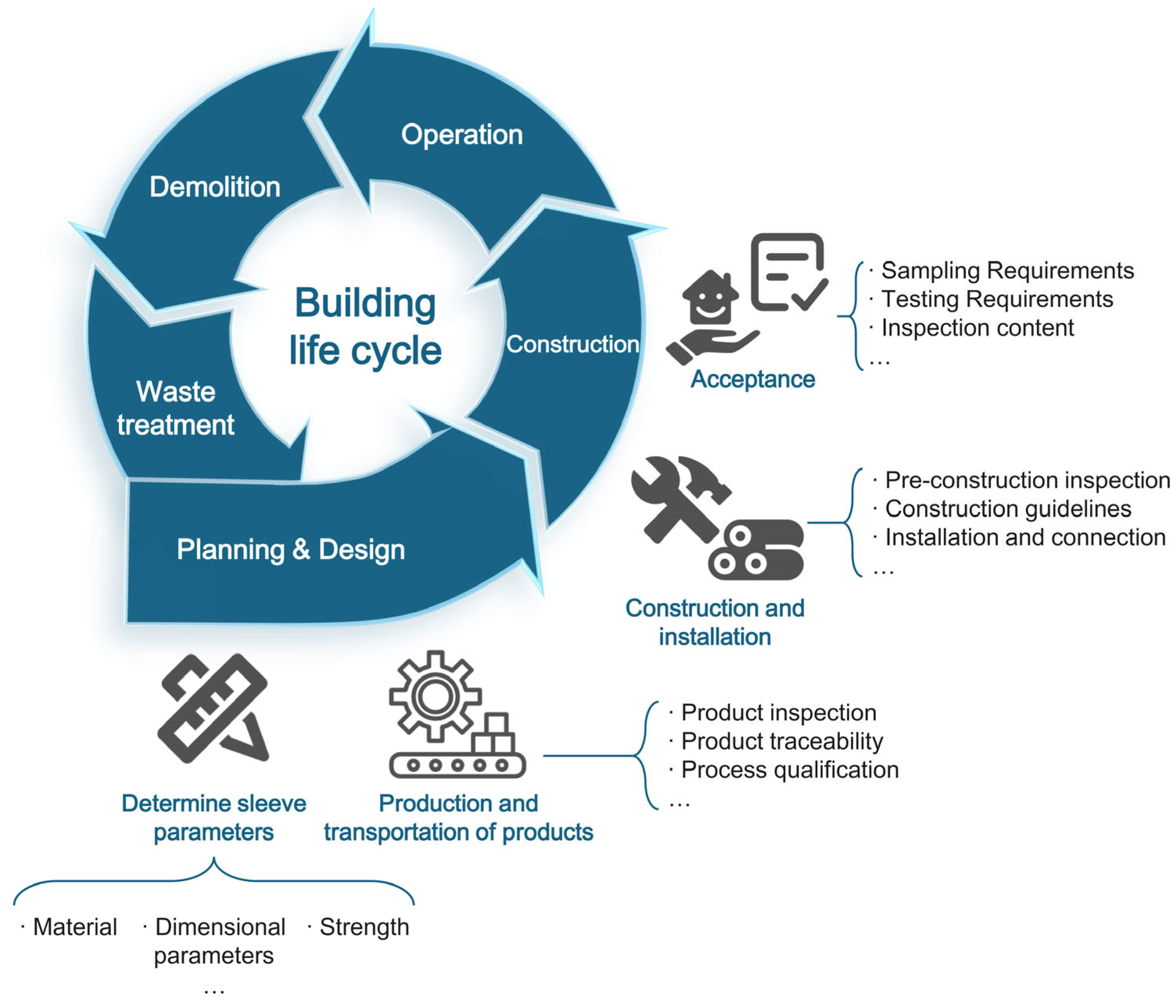
As GS components are factory-produced, comprehensive quality control measures are particularly crucial. Accordingly, standards typically define standardized requirements for all four key lifecycle stages—material and component manufacturing, planning and design, construction and transportation, and operation and maintenance.
In most of the existing standards, quality control (QC) requirements for GS—or for mechanical connectors in general—are typically addressed in design stipulations, mandatory construction procedures, and inspection and acceptance criteria (see Figure 6). This section will focus on quality control aspects of GS construction, specifically covering “Incoming product and material quality control”, “Installation and grouting quality control”, and “Acceptance requirements”.

3.2.1. Incoming Product and Material Quality Control

Due to differences in local environmental conditions, construction traditions, and material supply chains, the specifications for materials and manufacturing processes of grouted sleeves (GS) vary across international standards (Table 2). Chinese Standard JG/T 398-2019 [20] provides explicit recommended constituent materials for both cast and machined GS, specifying that cast GS shall be fabricated from ductile iron and further advising suitable material grades and corresponding properties. For machined GS, a broader range of material choices is proposed. This prescriptive approach helps ensure compatibility with high seismic activity, coastal corrosion concerns, and fire-resistance requirements commonly encountered in China. By contrast, Standard NZS 3101.1&2:2006 [32] in New Zealand prohibits the use of spheroidal graphite iron (Grade 500/7) and cast iron for mechanical anchors, noting that cast-iron connectors can be susceptible to casting defects or material brittleness under normal service temperatures [50].
Standards JG/T 398-2019 [20], JGJ 107-2016 [24], and NZS 3101.1&2:2006 [32] also recognize that manufacturing GS or couplers often involves heat treatment and cold-pressing, cold-rolling, or cold-forging methods. Chinese standards JG/T 398-2019 [20] and JGJ 107-2016 [24] adopt a process-oriented regulatory approach in this regard. In JGJ 107-2016 [24], for example, the recommended raw material for mechanically machined GS is 45# cold-rolled precision seamless steel tubes, which must be annealed.
JG/T 398-2019 [20], as an updated specification devoted specifically to grout sleeves, provides more detailed requirements by classifying sleeves according to their manufacturing processes, explicitly distinguishing cast-iron grout sleeves from machined steel sleeves, and stipulating separate material clauses for each process. For machined sleeves produced by hot rolling, forging, cold drawing, cold rolling, or cold pressing, the standard gives recommended raw materials and specifies an upper limit for ultimate tensile strength (≤800 MPa) and a lower limit for elongation (≥14%), together with post-forming heat-treatment recommendations (annealing or quenching and tempering). These numerical limits prevent the practice of boosting strength solely through severe cold working, which would introduce high residual stresses, increase brittleness, and lower ductility [51]. In other words, the design philosophy of JG/T 398-2019 [20] is not “the highest possible strength” but rather “sufficient strength with reliable toughness”, thereby ensuring the seismic, fatigue, and impact resistance of the connecting components.
Although ISO 15835-1:2018 [44] and ABNT NBR 9062:2017 [33] avoid prescribing or mandating specific materials, they require verification of fire resistance and biocompatibility. Current American, Australian, European, and international standards cede the choice and strength performance of sleeve materials to the manufacturer, accommodating variations in industrial capacity and opening the marketplace to additional producers. However, this flexibility increases reliance on post-production quality audits. In the absence of explicit material constraints, rigorous third-party verification of each production batch is warranted to mitigate variability—an especially pertinent concern for new materials lacking historical performance data.
Product traceability is an essential and effective mechanism to ensure that the materials, dimensions, and performance of GS connections meet specified requirements. Since GS connections are produced in a factory and then transported to the construction site for assembly into load-transferring structural components, any hidden defects or inconsistencies in materials arising during manufacturing may affect long-term structural performance. Hence, ensuring the qualification of GS products becomes particularly significant.
Table 3 presents the requirements and explanations related to product traceability under different standards. Chinese specifications include relatively detailed provisions for traceability inspections, especially JG/T 398-2019 [20], which stipulates multi-stage documentation, including raw material inspection reports, product quality certificates, and logistics tracking by delivery notes. Through this three-way verification, products are subjected to QC and traceability in a continuous chain. Compared to AC 133:1020 [45] and ASTM A1034/A1034M-24 [40] in the United States, one main difference is that Chinese standards do not require performance test reports for products in extreme temperature environments. This is attributable to the discrepancy shown in Table 2: American standards do not restrict GS to specific materials but rather demand that manufacturers meet certain performance standards, thus accommodating diverse industrial capabilities and fostering the development of new materials and products.
NZS 3101.1&2:2006 [32] adopts a performance-based philosophy, requiring only general quality assurance documentation without specifying a particular protocol for tracking product and batch materials. While this flexibility accommodates variations in the supply of materials, it also introduces potential risks due to the lack of defined batch-to-batch consistency. For example, in the case of steel sleeves, variations in the elemental composition and processing techniques across different batches can lead to measurable differences in mechanical properties and corrosion resistance [52,53].
JG/T 398-2019 [20] and ASTM A1034/A1034M-24 [40] incorporate raw material reporting requirements for GS or mechanical coupler traceability checks. Their fundamental emphasis on material lineage distinguishes them from performance-oriented standards such as ISO 15835-1:2018 [44] and NZS 3101.1&2:2006 [32]. Tracking raw materials can enhance integration across all phases of the building lifecycle, reduce design, construction, and maintenance costs [54], and, through the creation of material passports, promote and increase the sustainable economic value [55,56] and environmental benefits of the building process.
Because EN 1992 [35] and the Fib Model Code for Concrete Structures 2020 [27] serve as design-oriented standards, they do not specify detailed traceability protocols or requirements for raw materials.

3.2.2. Installation and Grouting Quality Control

Unlike traditional cast-in-place reinforced concrete connections, GS connections require specialized knowledge for on-site installation. Precise alignment and accurate grouting are critical to achieving the design load-carrying capacity and durability.
Uniquely, JGJ 355-2015 [23] specifies allowable positional and length deviations for grouted sleeves and protruding rebars during construction. For precast components, the maximum offset of the grouted sleeve and protruding bar center cannot exceed 2 mm, and the allowable range for the protruding bar length is from −10 to +10 mm [23]. For cast-in-place structures, the maximum offset increases to 3 mm, and the protruding bar length tolerance ranges from −15 to +15 mm [23]. By differentiating these requirements, the standard demonstrates the higher precision needed in precast construction. Compared to the performance-based deviation management approach utilized by some international standards—where a greater reliance on contractor expertise and post hoc load testing is common—Chinese standards mitigate the impact of construction uncertainties on structural performance and safety through strict pre-defined tolerances.
As shown in Table 4, two relevant standards—JGJ 355-2015 [23] and SESOC Guidance [41]—prescribe different grout material properties and construction control requirements for GS connections. Both standards highlight the significance of professional qualifications for grouting operations but differ in emphasis. Chinese Standard JGJ 355-2015 [23] mandates that personnel responsible for tasks such as sleeve grouting must remain in fixed positions and undergo specialized training. Meanwhile, the New Zealand SESOC Guidance [41] states that “grouting required for connections in precast concrete elements shall only be carried out by suitably trained and experienced specialist subcontractors”, reflecting diverse regulatory and contractual frameworks. JGJ 355-2015 [23] further details grout flowability and vertical expansion parameters, and JG/T 408-2019 [21] adds 28-day drying shrinkage requirements (≤0.045%) and a maximum chloride ion content (≤0.03%). In contrast, due to its more performance-oriented philosophy, SESOC Guidance [41] delegates specific determinations of grout fluidity and expansion ratio to manufacturers and contractors, affording greater flexibility.
Despite providing relatively thorough guidelines for factory production and on-site installation, GS connections may still encounter construction anomalies resulting from environmental factors, equipment issues, or human error. However, different standards address such contingencies to varying degrees. For instance, Chinese Standard JGJ 355-2015 [23] includes clauses stipulating supplementary grouting requirements for vertical and horizontal GS whenever incomplete grout filling or a significant drop in the grout mixture level is detected. Other standards either refer to following the manufacturer’s instructions or do not provide specific details on GS grouting, often due to the standard’s scope not explicitly classifying GS as a distinct type of reinforcing bar connector.

3.2.3. Acceptance Requirements

As a critical quality-control mechanism during construction, acceptance requirements entail strict sampling, testing, and evaluations according to established standards, thereby verifying whether materials and structural components are ready to transition into the next phase of the building’s service life. The minimal acceptance standard is effectively a rational decision framework that balances economic cost, structural safety, performance, and deterioration over time; raising reliability excessively often leads to disproportionate costs [57]. This trade-off underscores the variability of component-specific and standard-specific acceptance thresholds. Indeed, differences in underlying methodologies produce different acceptance criteria. For instance, Hawkins and Ghosh [58] propose validation-testing guidelines—including design procedures, specimen dimensions, loading protocols, and ultimate deformation acceptance—for precast concrete shear wall systems in seismically active regions. Straub and Der Kiureghian [59] emphasize that for structures facing long-term environmental effects, a single or short-term ultimate load “safety factor” is insufficient. Long-term durability under environmental corrosion, fatigue, and varying maintenance regimes must be systematically quantified at the system-level target reliability via adaptive degradation criteria that account for statistically correlated multi-failure events.
In most standards, the first step in acceptance involves checking the corresponding connection inspection reports (whose scope and format are partially outlined in Table 3 above). Requirements for connection performance reports differ across standards. Table 5 compares test methods required for the acceptance of GS connections or other mechanical connectors. Monotonic tension tests feature across all standards as a universally applicable criterion when assessing mechanical connectors. Cyclic tension–compression tests, geared towards evaluating long-term endurance or seismic performance, are not mandated by AS 3600:2018 [29] or ABNT NBR 8548:1984 [42]. Likewise, AS 3600:2018 [29] stipulates a relatively small minimum number of test specimens, whereas ABNT NBR 8548:1984 [42] omits explicit guidelines on specimen count.
Regarding environmental adaptability, only AC 133:1020 [45] integrates operational temperature tests into the acceptance criteria. Standards NZS 3101.1&2:2006 [32], EN 1992 [35], and the Fib Model Code for Concrete Structures 2020 [27] concentrate primarily on design principles and detailing rather than detailing acceptance testing at a granular level; consequently, they do not prescribe such environmental or durability tests during acceptance.

3.3. Construction Technical Details and Requirements

Since GS connections are frequently used in precast elements, clear specifications and proper controls of construction processes are crucial for ensuring construction quality. Given the diverse construction practices and environmental conditions worldwide, each standard emphasizes different aspects, often resulting in complementary requirements. Consequently, certain detailed constraints appear only in specific standards.
For instance, JGJ 355-2015 [23] explicitly states that GS-connected elements should not use concrete with a design strength class lower than C30 in the Chinese system (i.e., a 28-day cube compressive strength of 30 MPa for 150 mm specimens). In addition, under frequent earthquake load combinations, when a reinforced concrete component experiences tension across the entire cross section, all longitudinal reinforcement bars in a single cross section should not rely entirely on GS grouted sleeve connections. This requirement aims to prevent potential brittle failure and to improve overall seismic redundancy.
Differences also arise between Chinese Standard JGJ 355-2015 [23] and American Standard AC 133:1020 [45] in addressing environmental temperature for GS connection and grouting materials. JGJ 355-2015 [23] requires measuring ambient and grout-region temperatures prior to and during construction based on meteorological conditions and, subsequently, assigning appropriate construction methods for normal-temperature versus low-temperature grout depending on thermal compatibility. By contrast, AC 133:1020 [45] centers on the freeze–thaw durability of grout materials, mandating at least 300 freeze–thaw cycles per ASTM C666 [60], while maintaining a relative dynamic elastic modulus of no less than 90%. Nonetheless, for regions with less than 508 mm of annual precipitation and an average daily low temperature above −1.1 °C, freeze–thaw tests may be waived. Overall, JGJ 355-2015 [23] focuses on detailed measures for various temperature ranges and thermal insulation management, whereas AC 133:1020 [45] prioritizes material durability testing, allowing exemption from additional tests in dry, temperate climates.

4. Analysis of Differences in Design Provisions and Mechanical Performance

GS connections and other mechanical couplers provide direct load transfer for structural members. Under real-world conditions, these connections are subjected to multi-load combinations. For all types of building structures, the key fundamental parameters of GS or mechanical connections under static loads include tensile strength, ductility, and slip behavior. In seismic regions and for components exposed to repeated loading, cyclic load and fatigue performance are also critical indicators for assessing the long-term durability of connections under dynamic loads.
The coupling of code systems and technical requirements essentially reflects the process of translating engineering experience into quantitative design criteria. For example, ISO 15835-1:2018 [44] stipulates performance requirements for connections in terms of strength, deformation, slip, seismic considerations, and fatigue. This section compares the differences in design provisions and requirements across various standards and examines how those differences influence the mechanical performance of connections.

4.1. Value Range and Applicability Conditions

Table 6 compares the minimum tensile strength, ductility, permanent residual deformation (slip), and required minimum anchorage length for GS connections or mechanical couplers across various standards.
As the fundamental indicator of ultimate load-bearing capacity, the connection’s minimum tensile strength ensures structural integrity under axial tension. Chinese standards JG/T 398-2019 [20], JGJ 107-2016 [24], JGJ 355-2015 (2023 Edition) [23], international standards ISO 15835-1:2018 [44], and Australian AS 3600:2018 [29] specify requirements based on the ultimate tensile strength of the connected reinforcing bar, although they differ regarding the location within the connection at which failure must occur. American standards ACI-318-19 [22], AC 133:1020 [45], and New Zealand NZS 3101.1&2:2006 [32] each demand that connection tensile failure occur in the reinforcing bar with a minimum tensile strength of 1.25 f y . Owing to regional disparities in steel rebar grades and properties, the representative values for minimum tensile strength in Table 5 still need further quantification and comparison. Unlike other standards, Brazil’s mechanical coupler standard stipulates a yield–strength range f y g s for couplers.
In reinforced concrete structures, continuous rebars accommodate deformation primarily through strain elongation, whereas GS or other mechanical couplers often display more complex slip–strain mechanisms [7,8,9], leading to a slightly lower ductility performance for the connection under monotonic tension compared to the continuous bar itself. This explains why the international standard ISO 15835-1:2018 [44] includes the lowest ductility requirement among all the standards (≥0.7 A g t ). Meanwhile, the American standard ACI 318-19 [22] prescribes a ductility requirement that is approximately—or slightly—higher than the Chinese standards JG/T 398-2019 [20], JGJ 107-2016 [24], and JGJ 355-2015 [23], because the minimum total elongation A g t for any grade of steel rebar in the U.S. is set at 6%. Certain standards do not include ductility requirements for connections, possibly reflecting historical design practices or local seismic risk profiles; in low-seismic regions, static strength often takes precedence.
In seismically hazardous regions, code provisions ensure seismic performance by setting limiting values derived from tests under high-stress cyclic tension–compression (“HS1 test” in ISO 15835-1:2018 [44] and AC 133:1020 [45]) and large-deformation cyclic tension–compression (“S2 test” in ISO 15835-1:2018 [44] and AC 133:1020 [45]). ISO 15835-1:2018 [44] and the Chinese standards JG/T 398-2019 [20], JGJ 355-2015 [23], and JGJ 107-2016 [24] use identical methods, processes, and limiting criteria and are similar to AC 133:1020 [45] in this regard. For moderate seismic zones with lower seismic risk, the high-stress cyclic tension–compression test (S1) sets the tension upper limit at 0.9 f y ( 0.95 f y in AC 133:1020 [45]) and the compression lower limit at 0.5 f y , repeated for 20 cycles, with a permissible permanent residual deformation (slip) no greater than 0.3 mm. Under normal service conditions, service loads usually do not exceed 0.66 f y [61,62]. Setting the tensile upper limit at 0.9 f y achieves a balance between realistic loading conditions and the prevention of premature material failure by maintaining a safety margin below the yield point while still permitting assessment of the material’s behavior as it approaches its elastic limit.
In high-seismic-risk areas, a stricter large-deformation cyclic test (S2) is required; ISO 15835-1:2018 [44], JG/T 398-2019 [20], JGJ 355-2015 [23], JGJ 107-2016 [24], and AC 133:1020 [45] share an identical two-stage protocol:
(1)
Stage I: tension upper limit = 2 ε y (where ε y is the strain at yield strength f y ), compression lower limit = 0.5 f y , total of four cycles, with maximum allowable permanent residual deformation = 0.3 mm.
(2)
Stage II: tension upper limit = ε y , compression lower limit = 0.5 f y , total of four cycles, with maximum allowable permanent residual deformation = 0.6 mm.
By contrast, NZS 3101.1&2:2006 [32] employs a different test design and stricter residual strain requirements. Its cyclic tension–compression protocol is tailored around the inherent properties of the rebar and uses eight cycles with both the tension upper limit and compression lower limit at 0.95 f y . The residual strain in the connection must not exceed 1.1 times the residual strain measured in equivalent testing of the bar alone.

4.2. Effect of Parameter Variations on Mechanical Performance

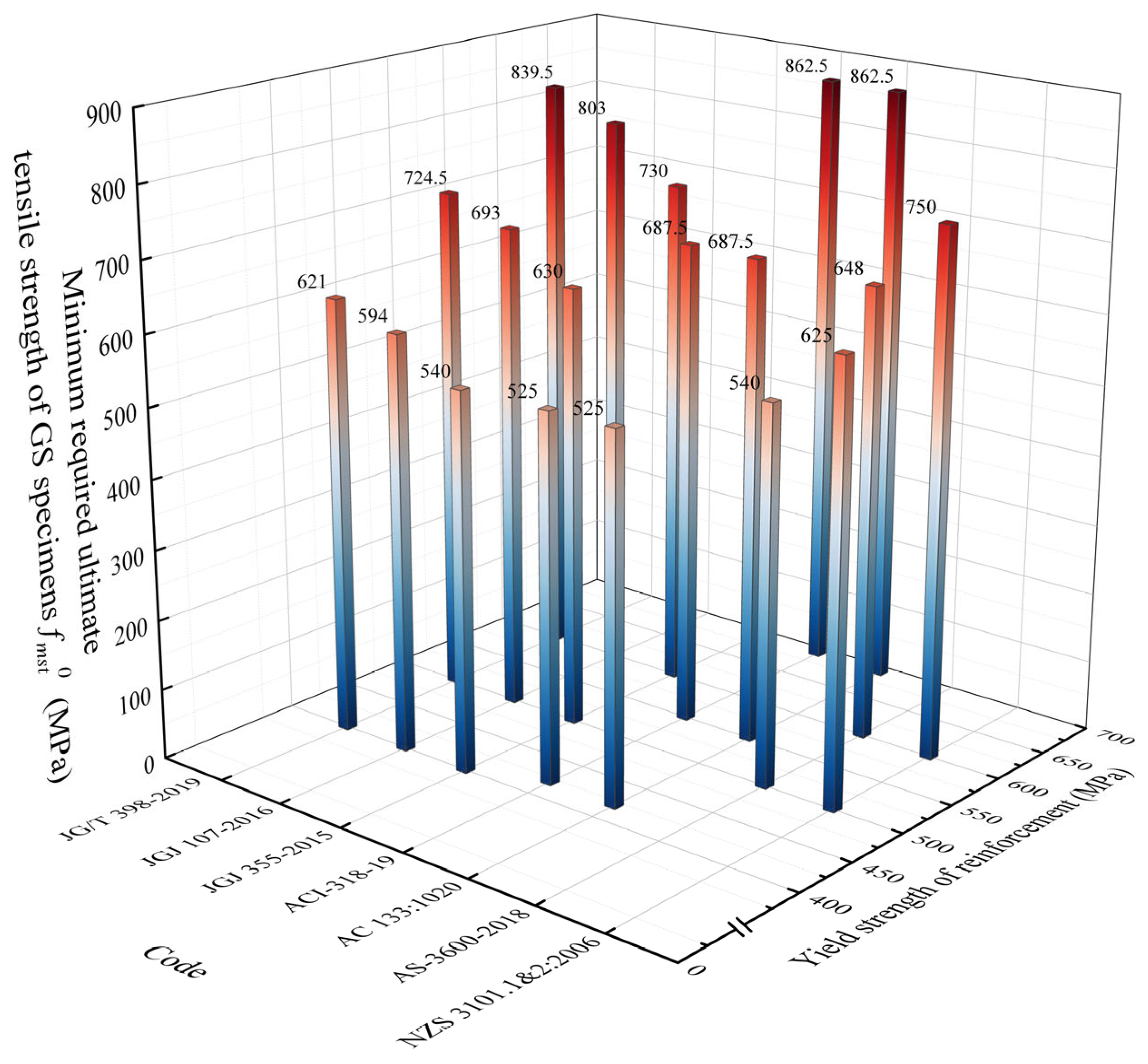
By comparing the minimum tensile strength requirements for connections under various standards—based on the performance parameters of A240, A400, A500, and A600 reinforcing steels specified in GOST 34028-2016 [63]—one obtains the results shown in Figure 7. The Chinese standards JG/T 398-2019 [20] and JGJ 107-2016 [24] consistently demand the highest values of f m s t 0 . Standards that adopt f s t k as the controlling factor—such as JGJ 355-2015 [23], AS 3600:2018 [29], and ISO 15835-1:2018 [44]—impose substantially higher f m s t 0 values on lower-yield-strength steels than do those standards ACI-318-19 [22], AC 133:1020 [45], and NZS 3101.1&2:2006 [32] that use 1.25 f y as the controlling basis. However, this discrepancy gradually diminishes as the steel’s yield-strength grade increases. When calculating for A500 steels ( f y = 5 00 MPa), once the yield-strength grade rises to 600 MPa, the required f m s t 0 in ACI 318-19 [22], AC 133:1020 [45], and NZS 3101.1&2:2006 [32] then exceeds that in JGJ 355-2015 [23], AS 3600:2018 [29], and ISO 15835-1:2018 [44] by 50 MPa.
Such a phenomenon arises from the varying material properties of different steel-strength grades, as well as distinct design philosophies. For low-strength steels (A240, A400) in GOST 34028-2016 [63], the ratio f s t k / f y typically remains relatively large. For high-strength steels (e.g., A500 and A600), that ratio becomes smaller because although their yield strength is significantly higher, their f s t k / f y ratio may decrease. Thus, standards controlling f m s t 0 based on f y can, in some cases, exceed f s t k and outstrip requirements in standards that use f s t k as the control. It should be noted that applying a unified requirement (same ratio limit) to both low-strength and high-strength steels under a single code may lead to overly conservative designs. Moreover, for high-strength steels, using a multiple of steel yield strength can be more conservative than directly adopting the ultimate tensile strength. For instance, 1.25 f y for A600 under GOST 34028-2016 [63] already exceeds the original value of f s t k .
Across the surveyed standards, every design requirement that restricts the grouted sleeve (GS) tensile capacity to a multiple of the bar’s yield strength adopts the same coefficient, 1.25 f y . Among the standard requirements that express the limit as a multiple of the bar’s specified ultimate strength f s t k , the smallest coefficient observed is 1.0. Keeping bar diameter, grout strength, and bond model constant, we recalculated the demands with the rebar grades and mechanical properties in GOST 34028-2016 [63]; the side-by-side results are given in Table 7. For the low-strength grades A240 and A400, the ratio λ = (1.25 f y )/ f s t k equals 0.79 and 0.83, showing that a design controlled by 1.25 f y calls for 17% and 21% less sleeve tensile capacity than one based directly on f s t k . When the grade rises to A500 and A600, λ increases to 1.04 and 1.07, so the minimum tensile requirement derived from 1.25 f y exceeds f s t k , adding strength reserve but also raising the material cost needed to achieve it.
Because of differences in metallurgical processes, yield-to-tensile ratios, and ductility reserves, countries and regions use various naming conventions and mechanical performance requirements for steel reinforcements. Table 8 summarizes common steel grades and their typical mechanical properties cited in different national or regional standards. These inherent variations in steel properties are a major reason for inconsistent requirements among standards worldwide. Although similarities exist in naming and performance parameters, certain steels do not maintain a simple correlation between nominal grade name and nominal yield strength. Another disparity lies in the tensile-to-yield strength ratio, with higher ratios indicating better ductility. However, owing to variations in metallurgical techniques, some regions find it challenging to maintain a ratio of 1.25 or greater—especially for high-strength steels [64]. Drawing upon the mechanical properties of different steels in Table 8 and considering each standard’s basic demand for ultimate tensile strength in GS or mechanical coupler connections, the outcomes shown in Figure 8 can be obtained.
From the results in Figure 8, the Chinese standards JG/T 398-2019 [20] and JGJ 107-2016 [24] have the largest structural-strength safety-redundancy requirements, followed by the Chinese standard JGJ 355-2015 [23], the United States standards ACI 318-19 [22] and AC 133:1020 [45], and the New Zealand standard NZS 3101.1&2:2006 [32], which are at approximately the same level. For connections using rebar with an approximate yield strength of 400 MPa, the minimum tensile capacity for grouted sleeves specified by the most stringent JG/T 398-2019 [20] is 104.54% of that in JGJ 107-2016 [24], 115% of that in JGJ 355-2015 [23], and 118.28% of that in ACI 318-19 [22] and AC 133:1020 [45]. When bars with an approximate yield strength of 500 MPa are connected, the minimum tensile requirement in JG/T 398-2019 [20] is 115.92% of that in NZS 3101.1&2:2006 [32] and 134.16% of that in AS 3600:2018 [29]. The comparatively low strength demand in the Australian standard AS 3600:2018 [29] may be related to Australia’s location deep within the Australian plate, far from plate boundaries, which makes it a typical stable craton.
It can be observed that, as the yield strength of the reinforcing bar increases, specifying the minimum tensile strength of GS or mechanical couplers based on a fixed multiple of the yield strength can frequently bring the required connection capacity close to, or even beyond, the bar’s own ultimate tensile strength. This phenomenon is far from an isolated case, occurring extensively in international applications of high-strength rebars. Generally, when the rebar’s yield strength is relatively low, the ratio of its ultimate tensile strength to yield strength remains fairly high. Thus, adopting “1.25 f y ” to define the coupler’s minimum required tensile strength typically does not exceed the material’s ultimate tensile strength, making this an economical and effective design approach for low- and medium-strength ranges. However, as the yield strength gradually increases to 500 MPa, 600 MPa, or even higher, the ultimate tensile strength does not rise in the same proportion, resulting in less available capacity for plastic deformation and strain hardening. Consequently, if a constant magnification factor (e.g., 1.25) is maintained for design, the required tensile capacity for mechanical couplers may approach or exceed the bar’s ultimate tensile strength itself. In the context of GS connections, this implies extra strength reserves or specialized manufacturing processes are needed to satisfy the requirement, leading, in high-strength ranges, to overly stringent and sometimes impractical demands.

5. Conclusions

Focusing on construction materials, product QC, and mechanical performance requirements for GS connections, this study has compared relevant design provisions, construction techniques, and acceptance criteria under various standards. Research on GS connections is primarily conducted in North America (the United States and Canada), South America (Brazil and Colombia), Europe (the United Kingdom, Germany, Switzerland, etc.), Asia (India, Iran, Malaysia, etc.), and Oceania (Australia and New Zealand). Comparative analysis shows that China (standards JG/T 398–2019 [20], JGJ 107–2016 [24], and JGJ 355–2015 [23]) has dedicated specifications specifically targeting GS connections, whereas the United States, Europe, and Oceania tend to regard GS as one of several mechanical coupler types subsumed under broader structural design regulations. This difference stems partly from varying seismic risk levels, engineering traditions, and building regulatory frameworks.
Regarding material traceability and quality control, the Chinese standards adopt a three-tier verification approach, comprising raw material inspection, product quality testing, and logistics tracking. Meanwhile, AC 133:1020 [45] and ASTM A1034/A1034M-24 [40] in the United States place more emphasis on validating performance under actual working conditions, and other standards employ more flexible, performance-based acceptance criteria. Concerning grout materials, JGJ 355-2015 [23] provides the most detailed parameters on flowability and vertical expansion, whereas standards such as the SESOC Guidance [41] grant manufacturers greater freedom in defining material properties. In construction environment control, JGJ 355-2015 [23] pays closer attention to specific construction measures and insulation management across different temperature ranges, while AC 133:1020 [45] employs durability testing of materials under given environmental conditions as its major control measure.
Through comparing the strength requirements for GS connections used with various steel grades, it was found that when the connected reinforcing steel’s yield strength is low, standards that set the GS connection’s tensile strength limit based on a multiple of the steel’s ultimate tensile strength (e.g., ISO 15835-1:2018 [44], AS 3600:2018 [29], JG/T 398-2019 [20], JGJ 107-2016 [24], and JGJ 355-2015 [23]) demand higher connection tensile strength than do standards that rely on a fixed multiple of the steel’s yield strength. However, as the steel grade increases, this trend may gradually reverse. A quantitative check using data in GOST 34028-2016 [63] shows that, as the strength grade of the connected rebars rises from A240 to A600, the ratio between the requirement “minimum GS tensile strength = 1.25 f y ” and the requirement “minimum GS tensile strength = f s t k ” climbs from 0.79 to 1.07. This means that, for high-strength steels, setting the GS connection’s minimum tensile capacity based on a multiple of the rebar’s yield strength may exceed the bar’s own ultimate tensile strength, leading to higher material demands and cost. This study also indicates that variations in yield-to-tensile ratios among steels of different countries constitute a key reason for divergent requirements across standards.
Based on this study, the following recommendations are proposed to enhance international standards for GS connection design and applications: (1) For GS connections with rebars of different yield-strength grades, adopt a more flexible strength requirement system. Avoid using a fixed ratio coefficient and instead determine requirements by taking into account the actual yield-to-tensile ratio of the steel so as to achieve both economic and performance targets. (2) In the current Brazilian standard system, ABNT NBR 8548:1984 [42], which was issued some time ago, fails to provide comprehensive design and acceptance requirements for high-strength rebars and advanced grouting materials. It also lacks specific provisions on fatigue testing and cyclic tension–compression testing. An update is urgently needed, supplementing it with reciprocating tension–compression, fatigue loading, and other performance tests dedicated to various mechanical coupler types. (3) When employing GS connections in different regions, the details of the standards should be suitably adjusted according to local environmental conditions, such as high humidity, severe cold, or high temperatures.
This study has the following limitations: The analysis of GS performance in different standards focuses primarily on static, monotonic tensile requirements, with relatively limited discussion of fatigue or durability testing requirements. Although minimum anchorage length and grout requirements under different standards have been compared, further research is called for to elucidate the impact of these differences on GS connection performance.

Author Contributions

S.X. and N.I.F.; methodology, S.X.; software, S.X.; validation, N.I.F., J.L., and J.G.; formal analysis, S.X.; investigation, S.X.; resources, S.X. and N.I.F.; data curation, S.X. and N.I.F.; writing—original draft preparation, S.X. and N.I.F.; writing—review and editing, S.X., N.I.F., J.L. and J.G.; visualization, S.X.; supervision, N.I.F.; project administration, S.X. and N.I.F.; funding acquisition, S.X. All authors have read and agreed to the published version of the manuscript.

Funding

The first author was supported by the [China Scholarship Council (CSC)] under grant number [202310100013].

Data Availability Statement

The original contributions presented in this study are included in the article. Further inquiries can be directed to the corresponding author.

Acknowledgments

The support from the China Scholarship Council (CSC) to the first author is gratefully acknowledged.

Conflicts of Interest

The authors declare no conflicts of interest.

Abbreviations

The following abbreviations are used in this manuscript:
GSgrouted sleeve
QCquality control
PGApeak ground acceleration
LRFDLoad And Resistance Factor Design
ULSUltimate Limit State
SLSServiceability Limit State

References

  1. Qin, C.; Bai, G.; Xu, Y.; Su, N.; Wu, T. Comparative Study of Seismic Behavior between Monolithic Precast Concrete Structure and Cast-in-Place Structure. Shock. Vib. 2018, 2018, 7029287. [Google Scholar] [CrossRef]
  2. Murashev, V.I. Crack Resistance, Stiffness and Strength of Reinforced Concrete; Publishing House of the Ministry of Construction of Machine-Building Enterprises: Moscow, Russia, 1950. [Google Scholar]
  3. Nikolyukin, A.N.; Yarcev, V.P.; Mamontov, S.A.; Kolomnikova, I.I.; Al’ Vard, A.M. Analysis of the stress-strain condition of concrete and reinforcement in the area of their engagement in the ansys software package. Bull. Belgorod State Technol. Univ. Named V. G. Shukhov 2019, 4, 43–52. [Google Scholar] [CrossRef]
  4. Demartino, C.; Vanzi, I.; Monti, G.; Sulpizio, C. Precast Industrial Buildings in Southern Europe: Loss of Support at Frictional Beam-to-Column Connections under Seismic Actions. Bull. Earthq. Eng. 2018, 16, 259–294. [Google Scholar] [CrossRef]
  5. AlAjarmeh, O.S.; Manalo, A.C.; Benmokrane, B.; Karunasena, K.; Ferdous, W.; Mendis, P. Hollow Concrete Columns: Review of Structural Behavior and New Designs Using GFRP Reinforcement. Eng. Struct. 2020, 203, 109829. [Google Scholar] [CrossRef]
  6. Lu, Z.; Huang, J.; Dai, S.; Liu, J.; Zhang, M. Experimental Study on a Precast Beam-Column Joint with Double Grouted Splice Sleeves. Eng. Struct. 2019, 199, 109589. [Google Scholar] [CrossRef]
  7. Sun, Y. Study of Mechanical Behavior of Grout Sleeve Splicing of Rebars. Front. Phys. 2024, 12, 1397218. [Google Scholar] [CrossRef]
  8. Zheng, G.; Kuang, Z.; Xiao, J.; Pan, Z. Mechanical Performance for Defective and Repaired Grouted Sleeve Connections under Uniaxial and Cyclic Loadings. Constr. Build. Mater. 2020, 233, 117233. [Google Scholar] [CrossRef]
  9. Alias, A.; Sapawi, F.; Kusbiantoro, A.; Zubir, M.A.; Rahman, A.B.A. Performance of Grouted Splice Sleeve Connector under Tensile Load. J. Mech. Eng. Sci. 2014, 7, 1094–1102. [Google Scholar] [CrossRef]
  10. Lu, Z.; Huang, J.; Li, Y.; Dai, S.; Peng, Z.; Liu, X.; Zhang, M. Mechanical Behaviour of Grouted Sleeve Splice under Uniaxial Tensile Loading. Eng. Struct. 2019, 186, 421–435. [Google Scholar] [CrossRef]
  11. Haber, Z.B.; Mackie, K.R.; Al-Jelawy, H.M. Testing and Analysis of Precast Columns with Grouted Sleeve Connections and Shifted Plastic Hinging. J. Bridge Eng. 2017, 22, 04017078. [Google Scholar] [CrossRef]
  12. Xiao, S.; Fomin, N.I. Development and Systematic Review of Connection Techniques for RC Precast Structural Elements: Beam and Column Connection. Heliyon 2024, 10, e35886. [Google Scholar] [CrossRef] [PubMed]
  13. Ferreira, M.A.; Bachega, L.A.; Catoia, B. Monolithic Equivalent Stiffness of Precast Columns with Grouted Splice Sleeve Connections. Rev. IBRACON Estrut. E Mater. 2021, 14, e14115. [Google Scholar] [CrossRef]
  14. Zhi, Q.; Yuan, Z.; Zheng, Y.; Jia, L.; Guo, Z. Experimental Research on Seismic Performance of Precast Concrete Shear Walls with a Novel Grouted Sleeve Used in the Connection. J. Earthq. Eng. 2024, 28, 1379–1403. [Google Scholar] [CrossRef]
  15. Jia, L.; Li, Q.; Zhang, Y.; Zhao, W.; Du, M. Experimental Study of the Hysteretic Behavior of Prefabricated Frame-Shear Wall Structures with Grouting Sleeve Connections. J. Build. Eng. 2022, 57, 104704. [Google Scholar] [CrossRef]
  16. Lei, S.; Liu, L.; Wu, F.; Lin, W.; Peng, K. Experimental Study on Tensile Mechanism of UHPC Grouted Sleeve Splice. Constr. Build. Mater. 2023, 364, 129922. [Google Scholar] [CrossRef]
  17. Guo, F.; Li, J.; He, S.; Zhou, C. Experimental Study on the Effect of Grouting Defects on Mechanical Properties of the Rebar Connected by Full-Grouted Sleeves. Adv. Civ. Eng. 2022, 2022, 5036505. [Google Scholar] [CrossRef]
  18. Ling, J.H.; Rahman, A.B.A.; Ibrahim, I.S. Behavior of Grouted Sleeve Wall Connection under Lateral Load. Indones. J. Comput. Eng. Des. 2024, 6, 1–16. [Google Scholar] [CrossRef]
  19. Zhang, W.; Deng, J.; He, C.; Zhang, J.; Yi, W. Experiment and Analysis on Mechanical Properties of Fully-Grouted Sleeve Connection at Elevated Temperatures. Constr. Build. Mater. 2020, 244, 118314. [Google Scholar] [CrossRef]
  20. JG/T 398-2019; The Grouting Sleeve for Rebars Splicing. Ministry of Housing and Urban-Rural Development of the People’s Republic of China Standards Press of China: Beijing, China, 2019.
  21. JG/T 408-2019; Cementitious Grout for Sleeve of Rebar Splicing. Ministry of Housing and Urban-Rural Development of the People’s Republic of China Standards Press of China: Beijing, China, 2019.
  22. ACI 318-19; Building Code Requirements for Structural Concrete. American Concrete Institute: Farmington Hills, MI, USA, 2019.
  23. JGJ 355-2015; Technical Specification for Grout Sleeve Splicing of Rebars (2023 Edition). Ministry of Housing and Urban-Rural Development of the People’s Republic of China Standards Press of China: Beijing, China, 2023.
  24. JGJ 107-2016; Technical Specification for Mechanical Splicing of Steel Reinforcing Bars. Ministry of Housing and Urban-Rural Development of the People’s Republic of China Standards Press of China: Beijing, China, 2016.
  25. Wu, C.; Xiao, X.; Ma, S.; Yang, C. Mechanical Performance and Failure Mode Judgment Criteria of Grouted Sleeve Connectors Considering Large Deformation and Grouting Compactness. Case Stud. Constr. Mater. 2024, 21, e03997. [Google Scholar] [CrossRef]
  26. Bing, H.; Yuan, H. Experimental Study on Bond Performance between Rebar and Grout and Confinement Effects of Grouted Sleeve Connections. Constr. Build. Mater. 2022, 354, 129088. [Google Scholar] [CrossRef]
  27. International Federation of Structural Concrete. Fib Model Code for Concrete Structures (2020); International Federation of Structural Concrete: Lausanne, Switzerland, 2023. [Google Scholar]
  28. GB 50010-2010; Code for the Design of Concrete Structures. Ministry of Housing and Urban-Rural Development China Architecture & Building Press: Beijing, China, 2010.
  29. AS 3600:2018; Concrete Structures Code. Council of Standards Australia Standards Australia International: Sydney, Australia, 2018.
  30. Sharma, L.K.; Abdullah, W.; Niroula, S.; Budhathoki, N.; Ghannoum, W.M. Performance of Mechanical Couplers of High-Strength Reinforcing Bars under Inelastic Strain Demands. ACI Struct. J. 2025, 122, 225–238. [Google Scholar]
  31. Seifi, P.; Henry, R.S.; Ingham, J.M. Panel Connection Details in Existing New Zealand Precast Concrete Buildings. Bull. New Zealand Soc. Earthq. Eng. 2016, 49, 190–199. [Google Scholar] [CrossRef]
  32. NZS 3101:2006 A3; Concrete Structures Standard. Standards New Zealand: Wellington, New Zealand, 2017.
  33. ABNT NBR 9062:2017; Design and Execution of Precast Concrete Structures. Associação Brasileira de Normas Técnicas: Rio de Janeiro, Brazil, 2017.
  34. Ye, H.; Lu, Y. Rebar-Concrete Bond Behaviour in Grouted Sleeve Connectors. Constr. Build. Mater. 2024, 431, 136487. [Google Scholar] [CrossRef]
  35. EN 1992; Eurocode 2: Design of Concrete Structures. European Committee for Standardization: Brussels, Belgium, 2004.
  36. Ghayeb, H.H.; Razak, H.A.; Sulong, N.H.R.; Mo, K.H.; Abutaha, F.; Gordan, M. Performance of Mechanical Steel Bar Splices Using Grouted Couplers under Uniaxial Tension. J. Build. Eng. J. 2021, 34, 101892. [Google Scholar] [CrossRef]
  37. BS 8110; Structural Use of Concrete. British Standards Institution: London, UK, 1997.
  38. JGJ 1-2014; Technical Specification for Precast Concrete Structures. Ministry of Housing and Urban-Rural Development of the People’s Republic of China Standards Press of China: Beijing, China, 2014.
  39. GB 50010-2010(2015); Code for Design of Concrete Structures (2015 Edition). Ministry of Housing and Urban-Rural Development of the People’s Republic of China China Construction Industry Press: Beijing, China, 2010.
  40. ASTM A1034/A1034M-24; Standard Specification for Mechanical Splices for Steel Reinforcing Bars. American Society for Testing and Materials: West Conshohocken, PA, USA, 2024.
  41. Structural Engineering Society New Zealand. Precast Concrete—Grouted Connections and Drossbachs—SESOC Guidance; Structural Engineering Society New Zealand: Wellington, New Zealand, 2022. [Google Scholar]
  42. ABNT NBR 6118:2023; Design of Concrete Structures. Associação Brasileira de Normas Técnicas: Rio de Janeiro, Brazil, 2023.
  43. ABNT NBR 8548:1984; Barras de Aço Destinadas a Armaduras de Concreto Armado Com Emenda Mecânica Ou Por Solda—Determinação Da Resistência à Tração. Associação Brasileira de Normas Técnicas: Rio de Janeiro, Brazil, 1984.
  44. ISO 15835-1:2018; International Organization for Standardization. Steels for the Reinforcement of Concrete—Reinforcement Couplers for Mechanical Splices of Bars. International Organization for Standardization: Geneva, Switzerland, 2018.
  45. AC 133; Mechanical Splice Systems for Steel Reinforcing Bars. International Code Council: Washington, DC, USA, 2020.
  46. Ordaz, M.G.; Cardona, O.-D.; Salgado-Gálvez, M.A.; Bernal-Granados, G.A.; Singh, S.K.; Zuloaga-Romero, D. Probabilistic Seismic Hazard Assessment at Global Level. Int. J. Disaster Risk Reduct. 2014, 10, 419–427. [Google Scholar] [CrossRef]
  47. Kwon, D.K.; Kareem, A. Comparative Study of Major International Wind Codes and Standards for Wind Effects on Tall Buildings. Eng. Struct. 2013, 51, 23–35. [Google Scholar] [CrossRef]
  48. ISO 9000:2015; Quality Management Systems—Fundamentals and Vocabulary. International Organization for Standardization: Geneva, Switzerland, 2015.
  49. Arditi, D.; Gunaydin, H.M. Total Quality Management in the Construction Process. Int. J. Project Manage. 1997, 15, 235–243. [Google Scholar] [CrossRef]
  50. Kirkcaldie, D.K.; Lloyd, J.N. Some Concrete Topics Being Addressed in New Zealand Transport Agency Bridge Manual Revisions—Shrinkage and Creep in Concrete: Mechanical Coupling of Reinforcing Steel. In Proceedings of the NZ Concrete Industry Conference 2013, Queenstown, New Zealand, 3–5 October 2013. [Google Scholar]
  51. Rudkins, N.T.; Modlen, G.F.; Webster, P.J. Residual Stresses in Cold Extrusion and Cold Drawing: A Finite Element and Neutron Diffraction Study. J. Mater. Process. Technol. 1994, 45, 287–292. [Google Scholar] [CrossRef]
  52. Xie, Q.; Suvarna, M.; Li, J.; Zhu, X.; Cai, J.; Wang, X. Online Prediction of Mechanical Properties of Hot Rolled Steel Plate Using Machine Learning. Mater. Des. 2021, 197, 109201. [Google Scholar] [CrossRef]
  53. Odusote, J.K.; Shittu, W.; Adeleke, A.A.; Ikubanni, P.P.; Adeyemo, O. Chemical and Mechanical Properties of Reinforcing Steel Bars from Local Steel Plants. J. Fail. Anal. Prev. 2019, 19, 1067–1076. [Google Scholar] [CrossRef]
  54. Peris Mora, E. Life Cycle, Sustainability and the Transcendent Quality of Building Materials. Build. Environ. 2007, 42, 1329–1334. [Google Scholar] [CrossRef]
  55. Munaro, M.R.; Tavares, S.F. Materials Passport’s Review: Challenges and Opportunities toward a Circular Economy Building Sector. Built Environ. Proj. Asset Manag. 2021, 11, 767–782. [Google Scholar] [CrossRef]
  56. Luscuere, L. Materials Passports: Optimising Value Recovery from Materials. Proceedings of the Institution of Civil Engineers–Waste and Resource Management; Thomas Telford Ltd.: London, UK, 2017; Volume 170, pp. 25–28. [Google Scholar]
  57. Melchers, R.E. Assessment of Existing Structures—Approaches and Research Needs. J. Struct. Eng. 2001, 127, 406–411. [Google Scholar] [CrossRef]
  58. Hawkins, N.M.; Ghosh, S.K. Acceptance Criteria for Special Precast Concrete Structural Walls Based on Validation Testing. PCI J. 2004, 49, 78–92. [Google Scholar] [CrossRef]
  59. Straub, D.; Der Kiureghian, A. Reliability Acceptance Criteria for Deteriorating Elements of Structural Systems. J. Struct. Eng. 2011, 137, 1573–1582. [Google Scholar] [CrossRef]
  60. ASTM C666-97; Standard Test Method for Resistance of Concrete to Rapid Freezing and Thawing. American Society for Testing and Materials: West Conshohocken, PA, USA, 2017.
  61. ANSI/AISC 360-10; Specification for Structural Steel Buildings. AISC Committee on Specifications: Nicosia, Cyprus, 2005.
  62. Yang, L.; Xing, Y. Experimental Study on High-Cycle Fatigue Properties of Q420C Steel at Room Temperature. Mater. Res. 2022, 25, e20210589. [Google Scholar] [CrossRef]
  63. GOST 34028–2016; Rolled Product Reinforcement for Ferroconcrete Structure Reinforcement. Izd-vo Standartov: Moscow, Russia, 2018.
  64. Tavio; Anggraini, R.; Raka, I.G.P.; Agustiar. Tensile Strength/Yield Strength (TS/YS) Ratios of High-Strength Steel (HSS) Reinforcing Bars. AIP Conf. Proc. 2018, 1964, 020036. [Google Scholar] [CrossRef]
  65. GB 1499.2-2024; Steel for the Reinforcement of Concrete—Part 2: Hot Rolled Ribbed Bars. China Standards Press: Beijing, China, 2024.
  66. ASTM A615/A615M-2024; Standard Specification for Deformed and Plain Carbon—Steel Bars for Concrete Reinforcement. American Society for Testing and Materials: West Conshohocken, PA, USA, 2024.
  67. DIN 1045-1:2023-08; Tragwerke Aus Beton, Stahlbeton Und Spannbeton—Teil 1: Planung, Bemessung Und Konstruktion. DIN Deutsches Institut Für Normung e. V: Berlin, Germany, 2023.
  68. BS 4449:2005+A3:2016; Steel for the Reinforcement of Concrete—Weldable Reinforcing Steel—Bar, Coil and Decoiled Product—Specification. The British Standards Institution: London, UK, 2016.
  69. AS/NZS 4671:2019; Steel for the Reinforcement of Concrete. Standards New Zealand: Wellington, New Zealand, 2019.
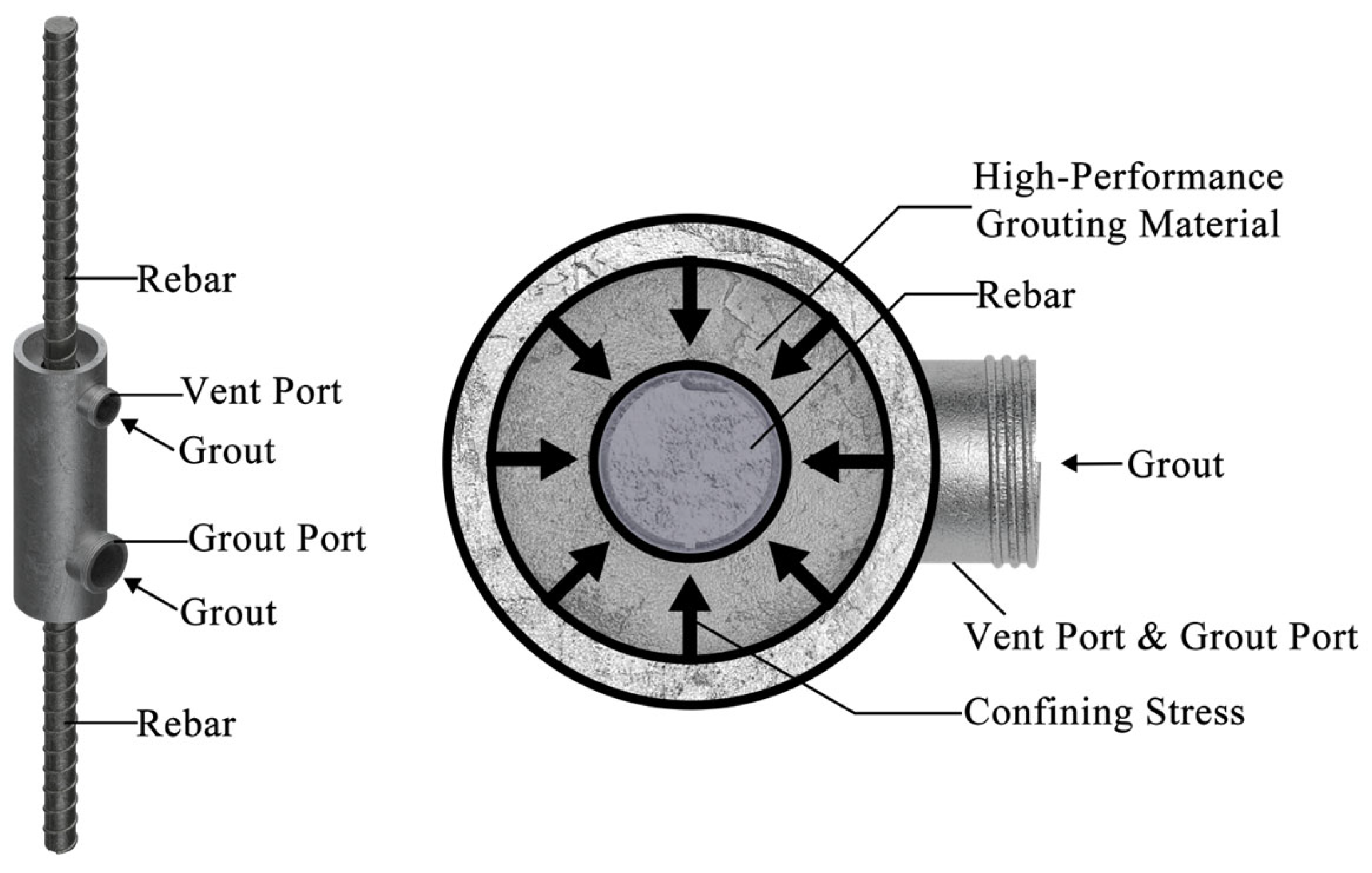
Figure 1. Schematic designs of the GS connection and the confining effect of the sleeve.
Buildings 15 01768 g001
Figure 2. Trends in the number of publications related to GS connections (2000–2024).
Buildings 15 01768 g002
Figure 3. International collaboration network for GS connection studies.
Buildings 15 01768 g003
Figure 4. Research roadmap.
Buildings 15 01768 g004
Figure 5. Global PGA seismic hazard distribution map (475-year return period) [46].
Buildings 15 01768 g005
Figure 6. Quality control requirements for GS in the building life cycle across current standards.
Buildings 15 01768 g006
Figure 7. Measured minimum required ultimate tensile strength of connection specimens f m s t 0 for reinforcement grades in GOST 34028-2016 [63] across different standards.
Buildings 15 01768 g007
Figure 8. The measured minimum required ultimate tensile strength of GS specimens f m s t 0 for approximate reinforcement grades across different standards.
Buildings 15 01768 g008
Table 1. Relevant standards and standards for GS connections.
Relevant Standard NameStandard NumberAuthorized
Institutions
Country/
Region
The Grouting Sleeve for Rebars Splicing [20]JG/T 398-2019Ministry of Housing and Urban–Rural Development of the People’s Republic of ChinaChina
Cementitious Grout for Sleeve of Rebar Splicing [21]JG/T 408-2019
Technical Specification for Mechanical Splicing of Steel Reinforcing Bars [24]JGJ 107-2016
Technical Specification of Grout Sleeve Splicing for Rebars (2023 Edition) [23]JGJ 355-2015
Technical Specification for Assembled Concrete Structures [38]JGJ 1-2014
Code For Design of Concrete Structures (2015 Edition) [39]GB 50010-2010(2015)
Building Code for Structural Concrete [22]ACI-318-19American Concrete InstituteUnited States
Standard Specification for Mechanical Splices for Steel Reinforcing Bars [40]ASTM A1034/A1034M-24American Society for Testing and Materials
Concrete Structures Code [29]AS 3600:2018Council of Standards AustraliaAustralia
Concrete Structures Standard [32]NZS 3101.1&2:2006Standards New ZealandNew Zeeland
Precast Concrete—Grouted Connections and Drossbachs—SESOC Guidance [41] Structural Engineering Society New Zealand
Design And Execution of Precast Concrete Structures [33]ABNT NBR 9062:2017Associação Brasileira de Normas TécnicasBrazil
Design of concrete structures [42]ABNT NBR 6118:2023
Steel bars for reinforced concrete with mechanical or welded seams—Determination of tensile strength [43]ABNT NBR 8548:1984
Eurocode 2: Design of concrete structures [35]EN 1992European Committee for StandardizationEuropean Union
Steels for the reinforcement of concrete—Reinforcement couplers for mechanical splices of bars [44]ISO 15835-1:2018International Organization for StandardizationGlobal
Mechanical Splice Systems for Steel Reinforcing Bars [45]AC 133:1020International Code Council
Fib Model Code for Concrete Structures 2020 [27] Fédération Internationale du Béton
Table 2. Standard-specific material and manufacturing requirements for GS or mechanical connectors.
StandardsProcessing MethodsRecommended or Requested Materials
JG/T 398-2019 [20]Cast GSDuctile iron
Machined GSCarbon structural steel; high-strength low-alloy structural steel; alloy structural steel; cold-drawn or cold-rolled precision seamless steel tube; and seamless structural steel tube
ACI-318-19 [22]No detail
AC 133:1020 [45]No detail
AS 3600:2018 [29]No detail
NZS 3101.1&2:2006 [32]No detailMechanical anchors and couplers manufactured from Grade 500/7 spheroidal graphite iron are not to be used; anchors manufactured from cast iron shall not be used
ABNT NBR 9062:2017 [33]No detailMechanical anchors must be able to withstand temperatures more than 80 °C and must also prove to be effective both during execution and for the lifetime of the building
ABNT NBR 6118:2023 [42]No detail
EN 1992 [35]No detail
ISO 15835-1:2018 [44]No detailIf a material other than steel is used in a coupler, the suitability for use of such material in fire-rated structures as well as any health implications should be evaluated
Fib Model Code for Concrete Structures 2020 [27]No detail
Cast GS refers to sleeves manufactured through metal casting processes. Machined GS denotes sleeves produced by subtractive machining from raw metal stock.
Table 3. Comparison of product traceability requirements for GS connection (or mechanical connection) materials and productions across different standards.
StandardsRaw MaterialsManufacturingTransportation
JG/T 398-2019 [20]+ (raw material inspection report)+ (product inspection report, product compliance certificate, product quality certificate, and manufacturer and lot identifications)+ (delivery note/outbound document)
JGJ 355-2015 [23]+ (product inspection report and product quality certificate)
AC 133:1020 [45]+ (acceptance criteria for quality documentation (AC10), test report, and freeze–thaw test report)
ASTM A1034/A1034M-24 [40]+ (certified mill test report)+ (certified mill test report, low-temperature test report, testing machine calibration certificate, and manufacturer and lot identifications)
AS 3600:2018 [29]
NZS 3101.1&2:2006 [32]+ (manufacturer’s or processor’s or supplier’s certificate)
ABNT NBR 9062:2017 [33]+ (inspection record documents for the production phase, test report, and manufacturer and lot identifications)
EN 1992 [35]
ISO 15835-1:2018 [44]+ (quality assurance documentation, test report, and manufacturer and lot identifications)
Fib Model Code for Concrete Structures 2020 [27]
Notation “+” indicates that the standard explicitly specifies traceability requirements and declares the required documents or criteria. Notation “−” indicates that the standard does not specify traceability requirements.
Table 4. Comparison of grout material properties and construction control requirements across different standards.
StandardsProfessional Qualification for Grouting OperationsGrout RecordCompressive Strength (7 Days) (MPa)Compressive Strength (28 Days) (MPa)Initial Fluidity (mm)30 Minutes Fluidity (mm)Bleeding RateVertical Expansion Rate (3 h) (%)
JGJ 355-2015 (2023 Edition) [23]+ (specialized training for construction personnel)+≥60 (Cylinder test strength)≥85 (Cylinder test strength)≥300≥2600%0.02~2
Precast Concrete—Grouted Connections and Drossbachs—SESOC Guidance [41]+ (qualified specialist subcontractor with experience)+≥40 (40 mm × 40 mm × 160 mm prism test strength)≥60 (40 mm × 40 mm × 160 mm prism test strength)0%
Notation “+” indicates that the standard explicitly specifies requirements. Notation “−” indicates that the standard does not specify requirements.
Table 5. Comparison of acceptance requirements for GS connections (or mechanical couplers) in tests across various standards.
StandardsMinimum Number of Specimens Per TestMonotonous Tensile TestCyclic Tensile and Compression TestFreeze–Thaw Test
JG/T 398-2019 [20]3++
JGJ 107-2016 [24]3++
JGJ 355-2015 (2023 Edition) [23]3++
AC 133:1020 [45]3+++
AS 3600:2018 [29]2+
ABNT NBR 8548:1984 [42]+
ISO 15835-1:2018 [44]3++
Notation “+” indicates that the standard explicitly specifies requirements. Notation “−” indicates that the standard does not specify requirements.
Table 6. Differences in GS (or mechanical coupler) performances and reinforcement anchorage length across various standards.
StandardsMinimum Connection’s Tensile Strength A s g t (%)Permanent Deformation Slip Limit (mm)Minimum Design Anchor Length Tested or Required
JG/T 398-2019 [20] f m s t 0 1.15   f s t k (at connection failure) 6.0 0.10   ( d s 32 )
0.14   ( d s > 32 )
8 d s
JGJ 107-2016 [24] f m s t 0 1.10   f s t k (at connection failure) 6.0 0.10   ( d s 32 )
0.14   ( d s > 32 )
8 d s
JGJ 355-2015 (2023 Edition) [23] f m s t 0 f s t k (at reinforcement failure) 6.0 0.10   ( d s 32 )
0.14   ( d s > 32 )
8 d s
ACI-318-19 [22] f m s t 0 1.25   f y (at reinforcement failure) A g t
AC 133:1020 [45] f m s t 0 1.25   f y (at reinforcement failure)
AS 3600:2018 [29] f m s t 0 f s t k (at reinforcement failure) 0.10
NZS 3101.1&2:2006 [32] f m s t 0 1.25   f y (at reinforcement failure)The specimen is stretched from zero load to f y , and the total displacement of the connector during loading shall not exceed twice the displacement of the control bar of the same length.
ABNT NBR 8548:1984 [42] 0.8   f y f y g s 0.7   f y
EN 1992 [35]- 10 d s [34]
ISO 15835-1:2018 [44] f m s t 0 f s t k 0.7 A g t 0.10
Fib Model Code for Concrete Structures 2020 [27] 10 d s
f y —specified yield strength for nonprestressed reinforcement; f s t k —standard value of ultimate tensile strength of nonprestressing steel bars; T u —calculated tensile strength of nonprestressing reinforcement obtained by applying the strength reduction factor; f y g s —measured ultimate yield strength of specimen; f m s t 0 —measured ultimate tensile strength of specimen; d s —nominal diameter of connected reinforcement; A s g t —elongation at maximum force from a single tensile test as a percentage of specimen; A g t —elongation at maximum force from a single tensile test as a percentage of specimen of connected reinforcement. Notation “−” indicates that the standard does not specify requirements.
Table 7. Comparison of minimum required values of GS tensile strength based on different design principles.
Reinforcement GradeTensile Strength Values Based on 1.25 f y as a Limit (MPa)Tensile Strength Values Based on f s t k as a Limit (MPa)Ratio of Tensile Strength Values Based on 1.25 f y as Limit to Based on f s t k as a Limit, λ
A2403003800.79
A400487.55900.83
A5006256001.04
A6007507001.07
Table 8. Approximate reinforcement grades and their mechanical parameters across various standards.
StandardsCountrySteel GradeYield Strength f y  (MPa)Tensile Strength f s t k  (MPa)
GOST 34028-2016 [63]RussiaA400390590
A500500 600   ( 1.05 f y )
A600600 700   ( 1.05 f y )
GB 1499.2-2024 [65]ChinaHRB400400 540   ( 1.25 f y )
HRB500500 630   ( 1.25 f y )
HRB600600730
ASTM A615/A615M-2024 [66]United StatesGrade 60420 550   ( 1.10 f y )
Grade 80550 690   ( 1.10 f y )
Grade 100690 790   ( 1.10 f y )
DIN 1045-1-2008 [67]Germany500M500 550   ( 1.10 f y )
BS 4449:2005 + A3:2016 [68]United KingdomB500A500 525   ( 1.05 f y )
B500B500 540   ( 1.08 f y )
B500C500 575   ( 1.10 f y )
AS/NZS 4671:2019 [69] New Zeeland500N500 540   ( 1.08 f y )
Australia600N600 648   ( 1.08 f y )
Disclaimer/Publisher’s Note: The statements, opinions and data contained in all publications are solely those of the individual author(s) and contributor(s) and not of MDPI and/or the editor(s). MDPI and/or the editor(s) disclaim responsibility for any injury to people or property resulting from any ideas, methods, instructions or products referred to in the content.