Article

Effect of Steel Slag Fine Aggregate on the Seismic Behavior of Reinforced Concrete Columns with Steel Slag Sand

by
Tianhai Zhao
1,
Dongling Zhang
1,2,
Qiang Jin
1,3,4,*,
Sen Li
1 and
Xuanxuan Liu
1
1
College of Hydraulic and Civil Engineering, Xinjiang Agricultural University, Urumqi 830052, China
2
College of Civil Engineering, Henan Vocational College of Water Conservancy and Environment, Zhengzhou 450008, China
3
Xinjiang Key Laboratory of Hydraulic Engineering Security and Water Disasters Prevention, Urumqi 830052, China
4
Xinjiang BIM and Prefabricated Engineering Technology Research Center, Urumqi 830052, China
*
Author to whom correspondence should be addressed.
Buildings 2025, 15(11), 1769; https://doi.org/10.3390/buildings15111769
Submission received: 10 April 2025 / Revised: 18 May 2025 / Accepted: 19 May 2025 / Published: 22 May 2025

Abstract

Steel slag aggregate (SSA), as a high-performance and sustainable material, has demonstrated significant potential in enhancing the mechanical properties of concrete and improving the bond behavior between reinforcement and the concrete matrix, thereby contributing to the seismic resilience of steel slag concrete columns (SSCCs). Nevertheless, the underlying mechanism through which SSA influences the seismic performance of SSCCs remains insufficiently understood, and current analytical models fail to accurately capture the effects of bond strength on structural behavior. In this study, a comprehensive experimental program comprising central pull-out tests and quasi-static cyclic loading tests was conducted to investigate the influence of SSA on bond strength and the seismic response of SSCCs. Key seismic performance indicators, including the hysteresis curve, equivalent viscous damping ratio, and ductility coefficient, were evaluated. The role of bond strength in governing energy dissipation and ductility characteristics was elucidated in detail. The results indicate that bond strength significantly affects the seismic performance of SSCC components. At an SSA replacement ratio of 40%, the specimens show optimal performance: energy dissipation capacity increases by 11.3%, bond–slip deformation in the plastic hinge region decreases by 10%, and flexural deformation capacity improves by 9% compared to the control group. However, when the SSA replacement exceeds 60%, the performance metrics are similar to those of ordinary concrete, showing no significant advantages. Based on the experimental findings, a modified bond–slip constitutive model for the steel slag concrete–reinforcement interface is proposed. Furthermore, a finite element model incorporating bond–slip effects is developed, and its numerical predictions exhibit strong agreement with the experimental results, effectively capturing the lateral load-carrying capacity and stiffness degradation behavior of SSCCs.

1. Introduction

In recent years, with the growing emphasis on sustainable development and increasingly stringent environmental protection requirements, the reuse of industrial waste has emerged as a key trend in the construction industry. Against this backdrop, steel slag aggregate concrete (SSC) has attracted considerable attention as a sustainable construction material due to its superior mechanical properties and environmental benefits [1,2]. Compared to plain concrete, SSC exhibits enhanced compressive strength and durability [3,4], while also contributing to the reduction in industrial waste accumulation and reliance on natural resources. Consequently, SSC plays a significant role in alleviating environmental burdens and advancing the construction sector toward green, low-carbon, and sustainable development.
Steel slag, as a substitute for natural aggregate, exhibits excellent mechanical properties and significant environmental benefits when used in concrete. However, existing research has primarily focused on the macroscopic mechanical performance of steel slag concrete (SSC), while systematic studies on the bond behavior between reinforcement and SSC remain relatively limited, particularly regarding the bond–slip behavior and its impact on the seismic performance of reinforced concrete columns. Previous studies have shown that compared with plain concrete (PC), SSC typically demonstrates higher compressive strength and a higher elastic modulus, mainly attributed to the rough surface texture, higher crushing strength, and potential hydraulic activity of steel slag aggregate (SSA) [3]. Nevertheless, excessive SSA replacement ratios may weaken these enhancement effects and adversely affect the workability of the concrete mix [5]. Moreover, it has been confirmed that factors such as the compressive strength, splitting tensile strength, and water-to-binder ratio of the concrete significantly influence the bond strength between the concrete and the reinforcement [4,5,6]. Higher SSA replacement ratios may indirectly reduce the effective water-to-binder ratio, further diminishing the bond performance at the steel–concrete interface [3,6]. Although the above studies have revealed the effect of SSA on concrete properties to some extent, there is still a lack of systematic and in-depth studies on the effect of SSA on the seismic performance of steel slag sand concrete columns.
In summary, although existing studies have revealed the effects of SSA on the mechanical properties of concrete at the material level, systematic and in-depth research on the influence of SSA on the bond performance and seismic behavior of steel slag aggregate concrete columns is still lacking. Therefore, conducting related experimental investigations to elucidate the mechanisms by which SSA content affects the steel–concrete interface properties and seismic response is of great theoretical and practical significance. The type of aggregate used significantly influences the seismic performance of concrete columns, a topic that has been extensively explored in previous studies. However, research on the seismic performance of steel slag aggregate concrete (SSC) components is limited, with most studies focusing on mechanical properties under static loading [7,8,9]. Research shows that aggregate type significantly affects the seismic performance of concrete columns. Steel slag aggregates have been proven to improve the seismic performance of steel tube–steel slag concrete columns [10,11]. These aggregates enhance load-bearing capacity and increase confinement and bond strength due to their expansive properties [12]. For recycled aggregates, Cai Ruxing [13] found that while recycled concrete columns have slightly lower energy dissipation compared to plain concrete columns, they perform better in lateral load bearing and ductility. K. Liu [14] noted that high replacement rates of recycled aggregates reduce durability but improve energy dissipation. Z. Chen [15] found that steel tube–recycled concrete columns exhibit excellent seismic performance, with a ductility index near 3.0 and an equivalent viscous damping ratio of between 0.323 and 0.360. For other aggregates, Baili J [16] showed that fiber-reinforced concrete columns outperform traditional concrete columns in strength and ductility. However, existing studies have not thoroughly explored how aggregate variations affect the bond strength between concrete and reinforcement, and its specific impact on seismic performance.
Bond strength plays a critical role in the seismic performance of reinforced concrete (RC) structures, directly affecting load capacity, ductility, and energy dissipation. However, the influence of bond strength on the seismic behavior of steel slag concrete columns (SSCCs) remains insufficiently understood. Previous studies have shown that steel slag aggregate (SSA) can significantly improve the bond strength between concrete and steel reinforcement [17,18]. Experimental results indicate that the bond strength at the interface between SSA concrete and steel tubes is approximately 14.7% higher than that of plain concrete, with further increases observed as the SSA replacement ratio and steel tube contact area grow [19,20,21]. Faleschini et al. [22] found by a center pull-out test that higher SSA content further enhances bond strength, primarily due to the aggregate’s hydraulic activity, high water absorption, and angular shape, which improve mechanical interlocking and chemical adhesion [23,24,25]. Alkhawaldeh [26] found that insufficient bond strength increases the slip between the reinforcement and the concrete, which reduces the load carrying capacity and ductility, by using center pull-out tests with beam tests. Qin [27] also demonstrated that members with higher bond strength exhibit improved ductility and energy dissipation under cyclic loading. These findings highlight that the SSA replacement ratio significantly affects bond performance and, consequently, seismic behavior. However, systematic studies on the seismic performance of SSCCs with varying SSA replacement ratios are still lacking. Further investigation is needed to clarify the underlying mechanisms and assess their engineering potential.
This study investigates the seismic performance of steel slag sand concrete columns (SSCCs) with varying replacement ratios, focusing on the influence of bond strength on the seismic behavior of the components. The experiments include central pull-out tests and quasi-static cyclic loading tests on SSCC columns with different steel slag sand replacement rates (r = 0%, 20%, 40%, 60%, 80%, and 100%) to evaluate their bond strength and seismic performance. The central pull-out test, a classical method, can accurately measure the bond strength, stress–slip relationship, and failure modes between reinforcement and concrete under controlled and ideal conditions. Previous studies have demonstrated its effectiveness in analyzing the effects of concrete material variations on bond performance [22,26,27]. Based on this, the present study employs pull-out tests to clarify the impact of steel slag aggregate on the bond performance between reinforcement and concrete, combined with cyclic loading tests to systematically analyze the hysteresis curves, ductility factors, stiffness degradation, energy dissipation capacity, and bearing capacity of columns with varying replacement ratios, assessing the role of bond strength in seismic performance. To verify the experimental results, a finite element model considering bond–slip effects was developed to simulate the load–displacement response of SSCCs under seismic loading and predict the stiffness degradation and energy dissipation capacity. This research provides an important theoretical foundation and technical support for the application of steel slag aggregate concrete in seismic design.

2. Experimental Program

2.1. Materials

The cement used in this experiment was ordinary Portland cement (P-O 42.5) produced by Urumqi Tianshan Cement Plant, with its chemical composition shown in Table 1 and Table 2. The superplasticizer employed was a high-efficiency polycarboxylate superplasticizer produced by KZJ New Materials Co., Ltd., Xiamen, China. with a water-reducing rate of 26%. The aggregates included coarse aggregate, natural fine aggregate, and steel slag fine aggregate. The coarse aggregate was natural crushed stone with a particle size range of 5 mm to 20 mm, and the natural fine aggregate was natural sand with a particle size range of 0.15 mm to 4.75 mm. The steel slag fine aggregate was sourced from Xinjiang Bayi Iron & Steel Co., Ltd., consisting of basic oxygen furnace steel slag, which was subjected to rapid quenching, steam evaporation, and other thermal treatments, followed by natural weathering for over a year to prevent hydration expansion due to free calcium oxide and magnesium oxide [28]. The slag was then crushed and sieved to obtain steel slag sand with a particle size range of 0.15 mm to 4.75 mm. The other physical properties of the aggregates are provided in Table 3, and the chemical composition of the steel slag is presented in Table 4. The reinforcement used in the experiment consisted of 8 mm and 16 mm hot-rolled deformed bars (HRB400) produced by Xinjiang Bayi Iron & Steel Co., Ltd. Tensile tests were conducted in accordance with the Chinese standard GB/T 228.1-2010 [29] to obtain the yield strain, yield strength, and ultimate strength of the reinforcement, with the specific data listed in Table 5.

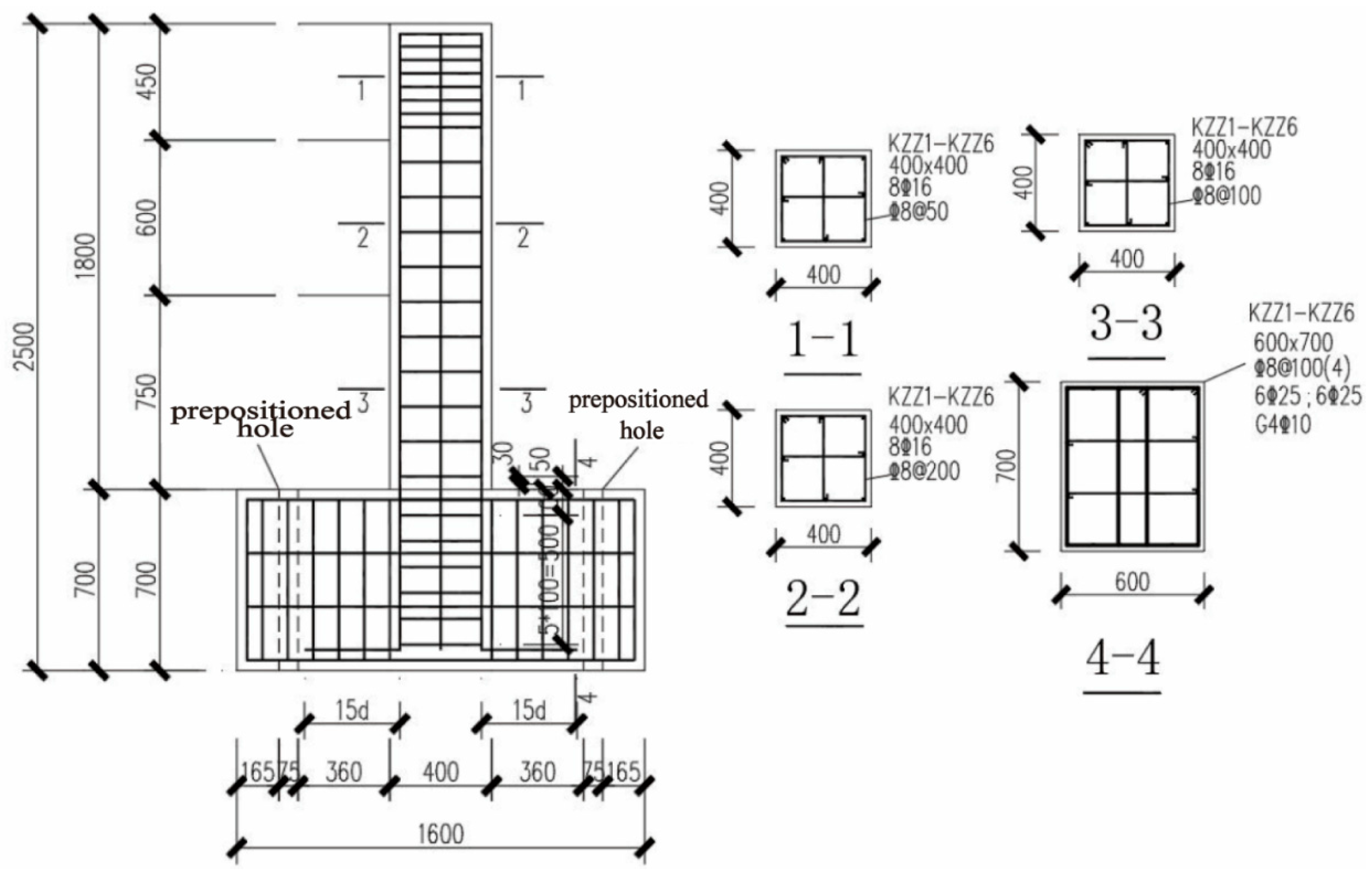
2.2. Experimental Design

Steel slag sand offers clear advantages in engineering performance, cost efficiency, and environmental sustainability. Its use in concrete enhances mechanical properties, improves bond strength with reinforcement, and reduces costs related to raw materials and waste management. Market data from Urumqi, Xinjiang, show that the cost of steel slag stockpiling is about CNY 25/ton, while crushing, screening, and stabilizing steel slag sand costs around CNY 12/ton. In contrast, processing steel slag powder costs CNY 100–120/ton. The use of steel slag sand also reduces solid waste accumulation and lessens the environmental impact of natural aggregate extraction. Although the short-term economic benefits are modest, its application potential will grow with technological and industrial advancements. Overall, the rational use of steel slag sand can enhance both economic and environmental outcomes, supporting sustainable development in the construction industry.
Given the comprehensive advantages of steel slag sand in material performance and sustainability, it is essential to further clarify its engineering applicability in structural components. Therefore, this study designed a series of experiments to systematically evaluate the effects of different steel slag sand replacement ratios (0%, 20%, 40%, 60%, 80%, 100%) on the seismic performance of reinforced concrete (RC) columns, and further analyze the variation in bond strength and its mechanism of action on the seismic behavior of the RC columns. A total of 56 concrete specimens were designed and fabricated to measure the basic mechanical properties of steel slag sand concrete (Figure 1a) and bond strength (Figure 1b), as well as 6 RC columns to evaluate the seismic performance of steel slag sand concrete columns (Figure 1c). The column section size at the top of the specimens was 400 mm × 400 mm, with a column height of 1800 mm. The bottom beam dimensions were 1600 mm × 550 mm × 700 mm, and the shear span ratio was 4. For structural reinforcement, longitudinal bars of HRB400, 8C16 were used, with a longitudinal reinforcement ratio of 1.27%. The transverse stirrups were also HRB400, with three-legged stirrups C 8@50/100/200, and a stirrup volumetric ratio of 1.04. The design of the components adhered to the structural requirements specified in the Chinese standards GB/T50010-2010 [30] and GB/T50011-2010 [31], with the detailed design shown in Figure 2.

2.3. Concrete Mix Design

The concrete mix design was based on the Chinese standard JGJ 55-2011 [32] and the previous research by our group [4,6]. The target strength grade was C30, with a 28-day cube compressive strength of 30 MPa and an estimated axial compressive strength of about 21 MPa. Steel slag sand replaced natural sand on an equal-volume basis. To account for its higher water absorption and rougher surface, the water reducer dosage was increased to maintain workability. The detailed mix proportions are shown in Table 6. C-1 represents ordinary concrete made with natural aggregates, while C-2 to C-6 represent steel slag sand concrete with varying replacement ratios.

2.4. Testing Procedure

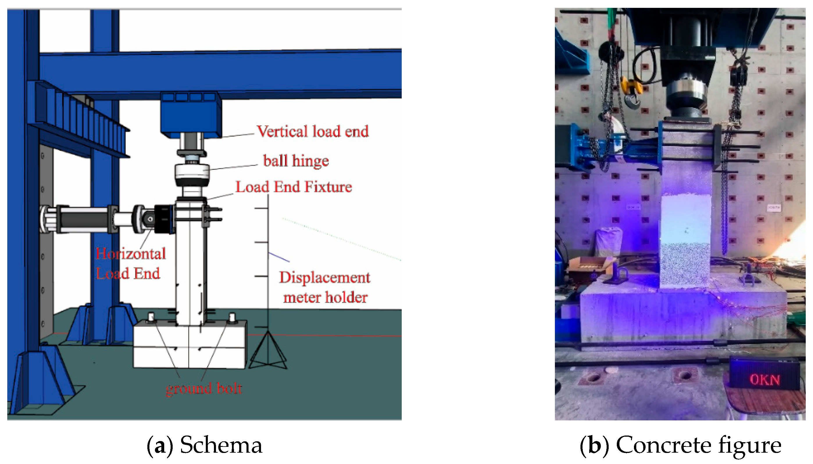
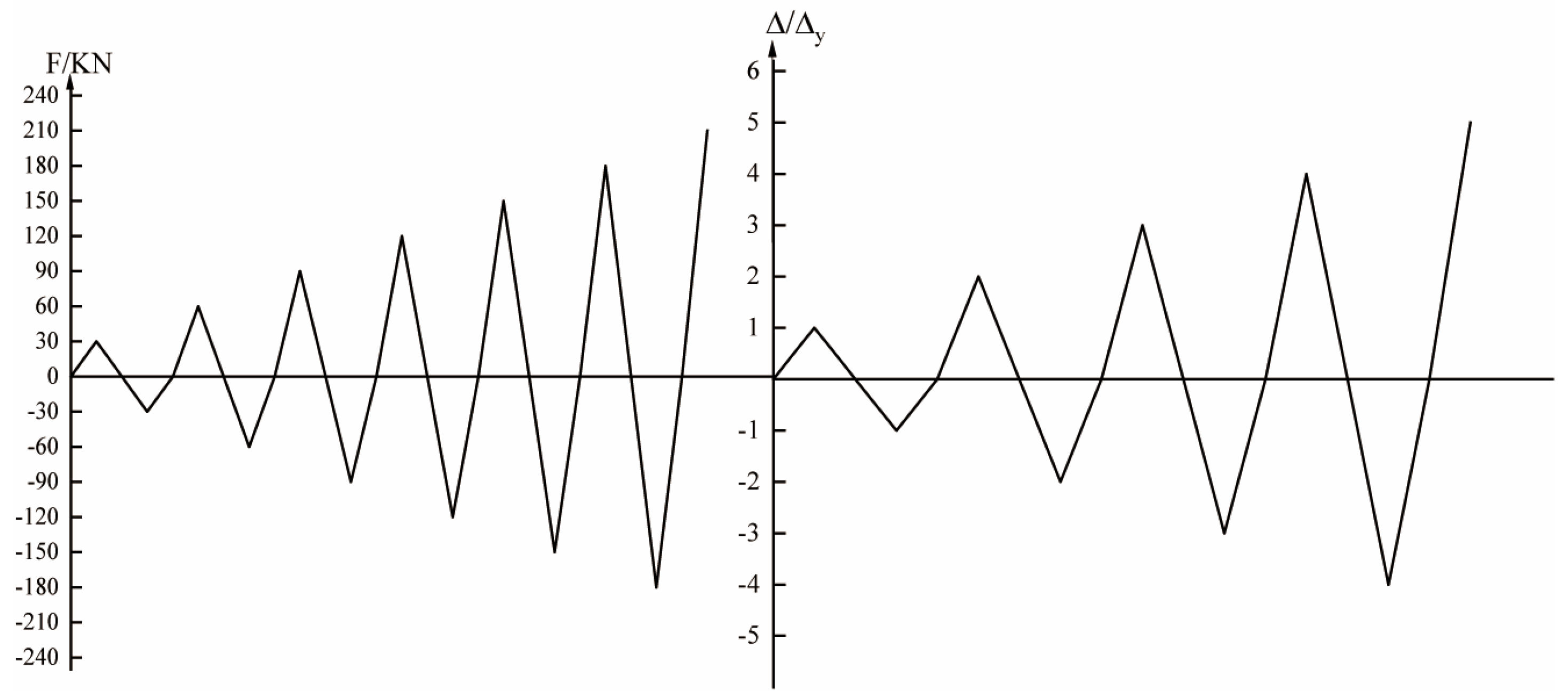
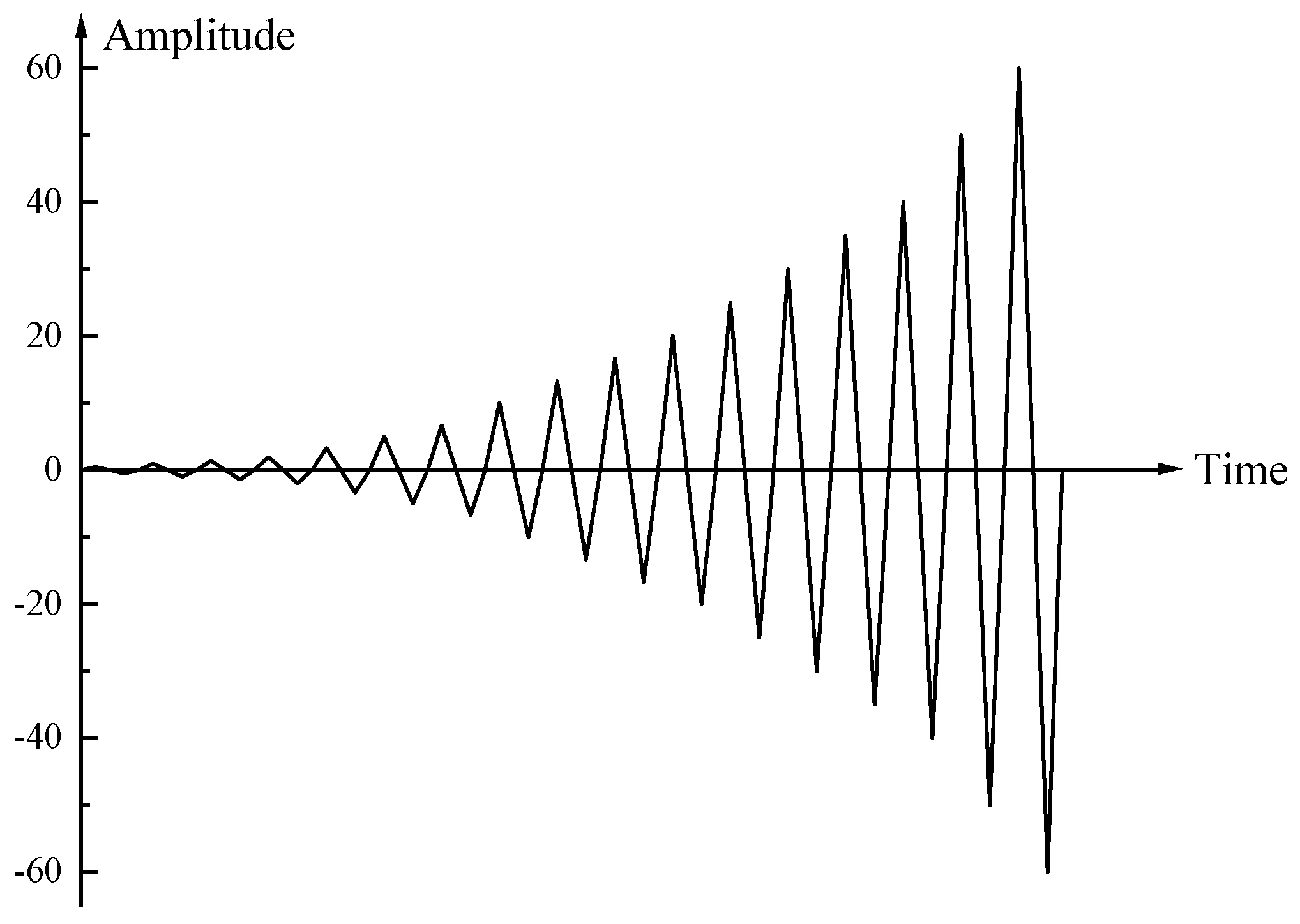
2.4.1. Loading Scheme

The experiment was conducted in the Structural Engineering Laboratory of the College of Civil Engineering at Xinjiang Agricultural University. The main tests included the compressive test of the steel slag sand concrete, the central pull-out test of the rebar–concrete specimens, and the quasi-static test of the steel slag sand concrete columns. In the compressive test of the steel slag sand concrete, both cubic axial compression tests and uniaxial compression tests were performed on a YES-2000 testing machine, which has a maximum load capacity of 2000 kN and a loading rate of 0.2 mm/min. The tests measured the standard compressive strength (fcu) and axial compressive strength (fc) of the steel slag sand concrete. The rebar–concrete central pull-out test was conducted on a 100 kN universal testing machine. The load was applied at a rate of 0.5 mm/min, with a displacement gauge placed at the free end to measure the bond–slip behavior between the steel slag sand concrete and the reinforcement.
The quasi-static test of the steel slag sand concrete columns was conducted using a JAW-2000SJ multi-channel electro-hydraulic servo loading system (Hangzhou Bangwei Mechatronic Control Engineering Co, Ltd., Hangzhou, China) to evaluate their seismic performance. During the test, a 200-ton vertical actuator applied vertical axial pressure, while a 100-ton horizontal actuator applied horizontal load. After securing the bottom beam to the ground with anchor bolts, low-cycle reverse loading tests were performed on the steel slag sand concrete columns. The specific loading setup is shown in Figure 3. The loading protocol strictly followed the quasi-static test method outlined in the Chinese standard JGJ/T101-2015 [33], employing a force–displacement hybrid control mode. Before the main loading, a preload test was conducted with a preload value of 5 kN, which was cycled once and unloaded back to zero. The formal loading then began. Prior to yielding the specimen, load control was used, with an increment of 30 kN per level, and each level was cycled once. After yielding, displacement control was applied, and loading was staged based on the maximum displacement of the specimen when the longitudinal reinforcement yielded, with each load level cycled three times. The loading was stopped when the peak horizontal load decreased to 75%, and the specific loading process is shown in Figure 4.

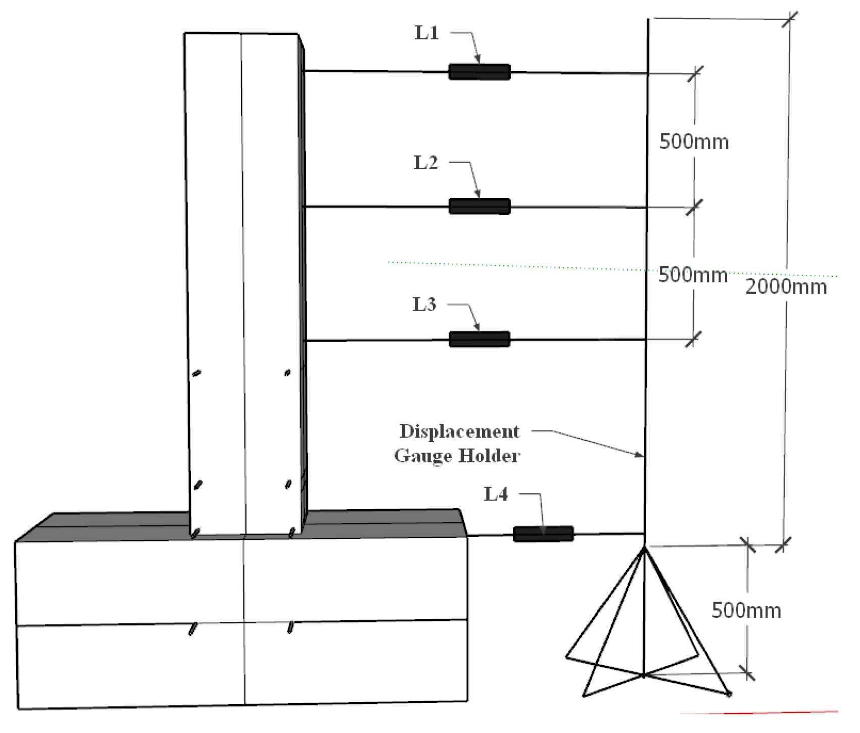
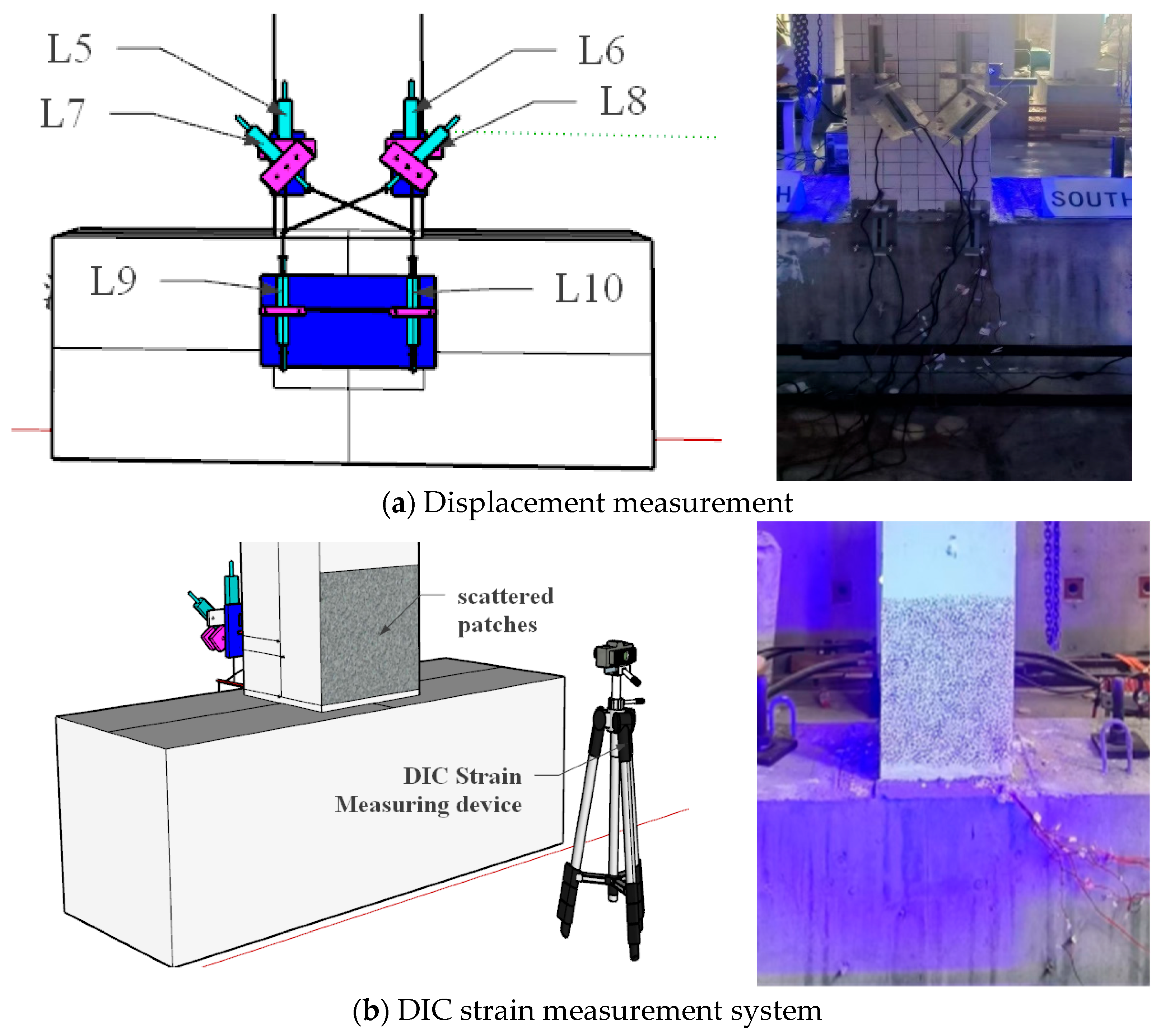
2.4.2. Measurement Scheme for Concrete Column Deformations

(1)
Measurement of Specimen Deformations
A displacement transducer L1 was installed at the top of the column to measure the horizontal displacement (Δ) at the column top under the action of the horizontal load (P). Below displacement transducer L1, additional displacement transducers (L2 and L3) were installed at 500 mm intervals along the column to monitor the displacement changes along the column’s height. To measure the horizontal displacement of the bottom beam under the horizontal force, a displacement transducer L4 was installed at the top of the bottom beam. All of these displacement transducers are linear displacement sensors with a measurement range of ±200 mm. The specific arrangement of the displacement transducers is shown in Figure 5.
(2)
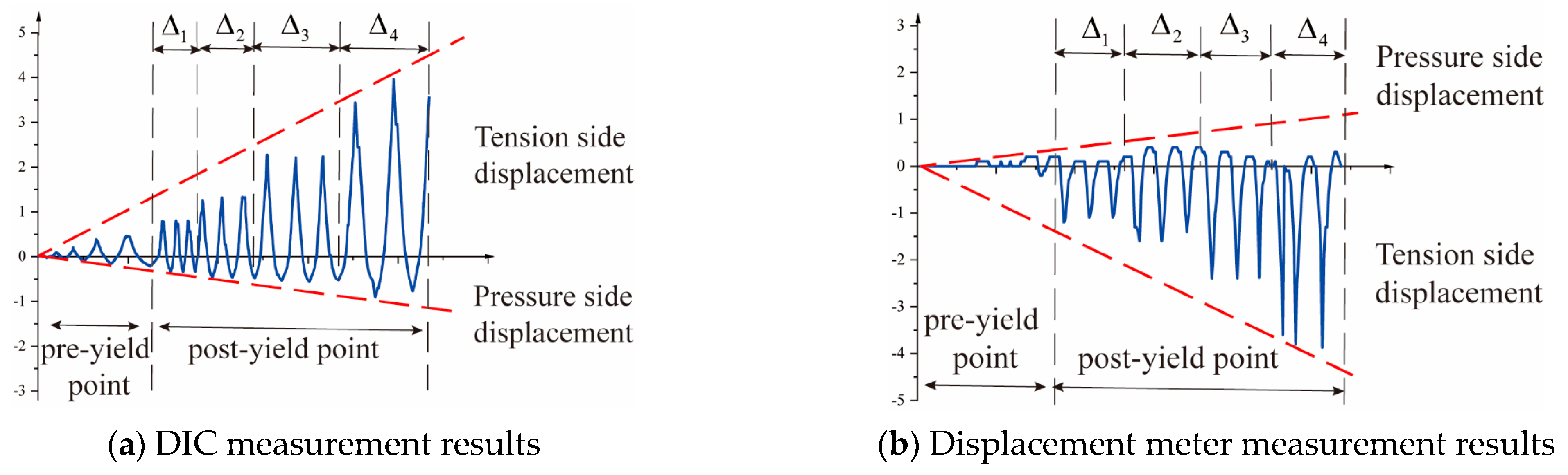
Measurement of Plastic Hinge Deformation
The deformation in the plastic hinge region primarily comprises bending deformation (Δfp), shear deformation (Δs), and bond–slip deformation of the longitudinal reinforcement (Δslip) [34,35]. In this study, a measurement device for the plastic hinge region deformation was designed, as shown in Figure 6a, to accurately quantify the bending deformation, shear deformation, and bond–slip deformation in the plastic hinge region. This device is fixed to the test column using M8 bolts. Linear displacement sensors (YHD-50) labeled L5 and L6 are employed to measure the bending deformation in the plastic hinge region, while L7 and L8 are used to measure the shear deformation in the same region. Linear displacement sensors (YHD-100) labeled L9 and L10 are utilized to measure the bond–slip deformation. Furthermore, a speckle pattern is applied to the opposite side of the column’s measurement device, and the XTDIC-3D non-contact field strain measurement system (DIC system) is employed to capture the concrete deformation in the plastic hinge region, as shown in Figure 6b. By comparing these measurements with the results from the displacement sensors, a more accurate analysis of the specimen’s deformation behavior can be achieved, and the crack formation and development trends of the steel slag sand concrete column can be observed.
(3)
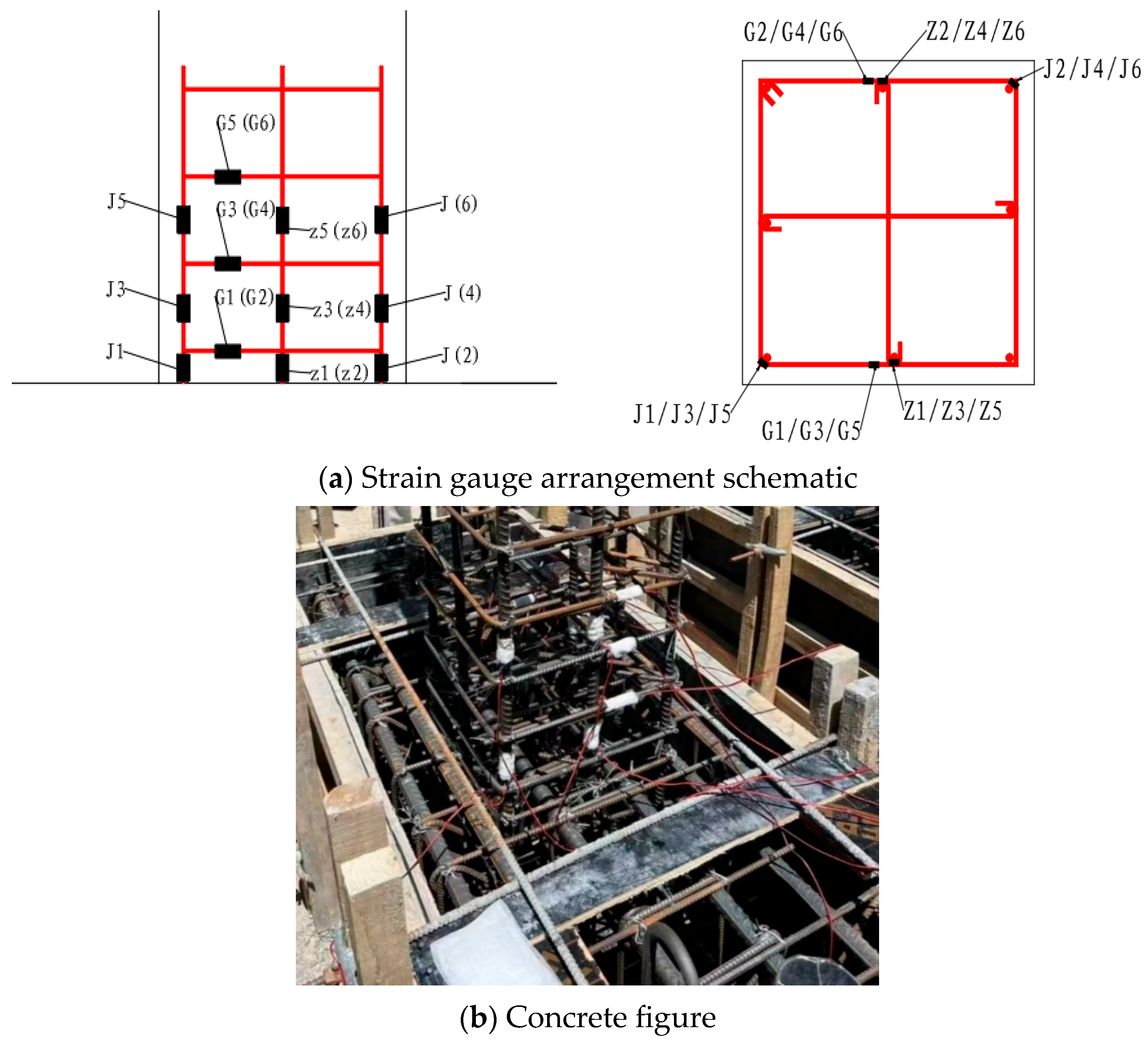
Reinforcement Strain Measurement
The strain measurement scheme for the reinforcement in the experiment is shown in Figure 3, Figure 4, Figure 5, Figure 6, Figure 7 and Figure 8. The strain gauges used are resistance-type. J1–J6 are the strain gauges on the longitudinal reinforcement at the corners of the column, with a sensitive grid size of 5 mm × 3 mm, symmetrically attached at the corners. Z1–Z6 are the strain gauges on the longitudinal reinforcement at the middle of the column, with a sensitive grid size of 5 mm × 3 mm, symmetrically attached. G1–G6 are the strain gauges on the stirrups, with a sensitive grid size of 3 mm × 2 mm, and are attached to three stirrups at the bottom of the column, with each strain gauge symmetrically positioned on the stirrups. During the experiment, the displacement meter and strain gauge readings are collected using the DH3816 static strain acquisition system (Donghua Testing Co., Ltd., Jingjiang, China), with a sampling frequency of 1 Hz.

3. Experimental Results and Analysis

3.1. Basic Mechanical Properties of Steel Slag Sand Concrete (SSC)

In the compressive strength test, the failure modes of the PC and SSC specimens were generally similar. In the steel bar–concrete pull-out test, when the steel slag sand substitution rate exceeded 60%, concrete splitting failure occurred, while the other specimens exhibited steel bar pull-out failure. The average values of the cube compressive strength (fcu), the axial compressive strength of the prismatic specimens (fc), and the bond strength ( τ ) are shown in Table 7. The test results indicate that the cube compressive strength (fcu) and axial compressive strength (fc) initially increased and then decreased with the increase in the steel slag sand substitution rate (r). The most significant improvement in compressive strength was observed at 20% and 40%, with increases of 18.5% and 17.7%, respectively, compared to ordinary concrete. This improvement can likely be attributed to the higher hardness, porous characteristics, and angular shape of the steel slag, which enhance the friction between the aggregates and the cement paste. Moreover, due to the similar chemical composition of steel slag and cement, more C-S-H gel and calcium aluminate phases can form during the hydration process, further improving the interface bond and thus enhancing compressive strength [36,37,38]. Zghair H H drew a similar conclusion in their study on the microstructure of concrete [39]. However, when r > 60%, the high-water absorption rate and greater friction of the steel slag aggregates reduced the workability of the concrete, leading to an increase in internal pores and microcracks, which in turn caused a decrease in compressive strength [38]. Nevertheless, the compressive strength of all specimens still meets the standard requirements.

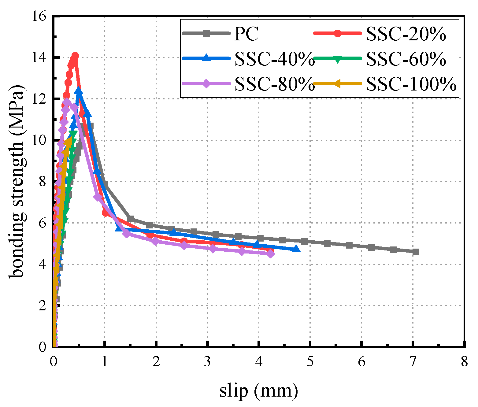
3.2. Bond–Slip Properties of SSC with Steel Bars

Compared to ordinary concrete, the SSC specimens showed a significant increase in bond strength with ribbed steel bars, as shown in Table 7, consistent with most studies [18,19,20]. When the substitution rate (r) was 20% and 40%, bond strength increased by 36.1% and 30.4%, respectively. However, when r > 60%, the failure mode changed, and some specimens showed bond strengths similar to or slightly lower than those of the PC specimens, likely due to reduced concrete density and premature cracking [39]. Additionally, the curve for the steel slag sand concrete had a steeper slope and a smaller peak slip displacement (Su) than those of ordinary concrete (Figure 8). This is because the increased stiffness of steel slag sand concrete enhances its brittleness, allowing it to withstand higher loads at small deformations. However, beyond a critical stress threshold, the material fails quickly, leading to a reduced Su. The peak bond stress and residual stress for the steel slag sand concrete were also higher than those of ordinary concrete, aligning with Faleschini et al.’s findings [22].

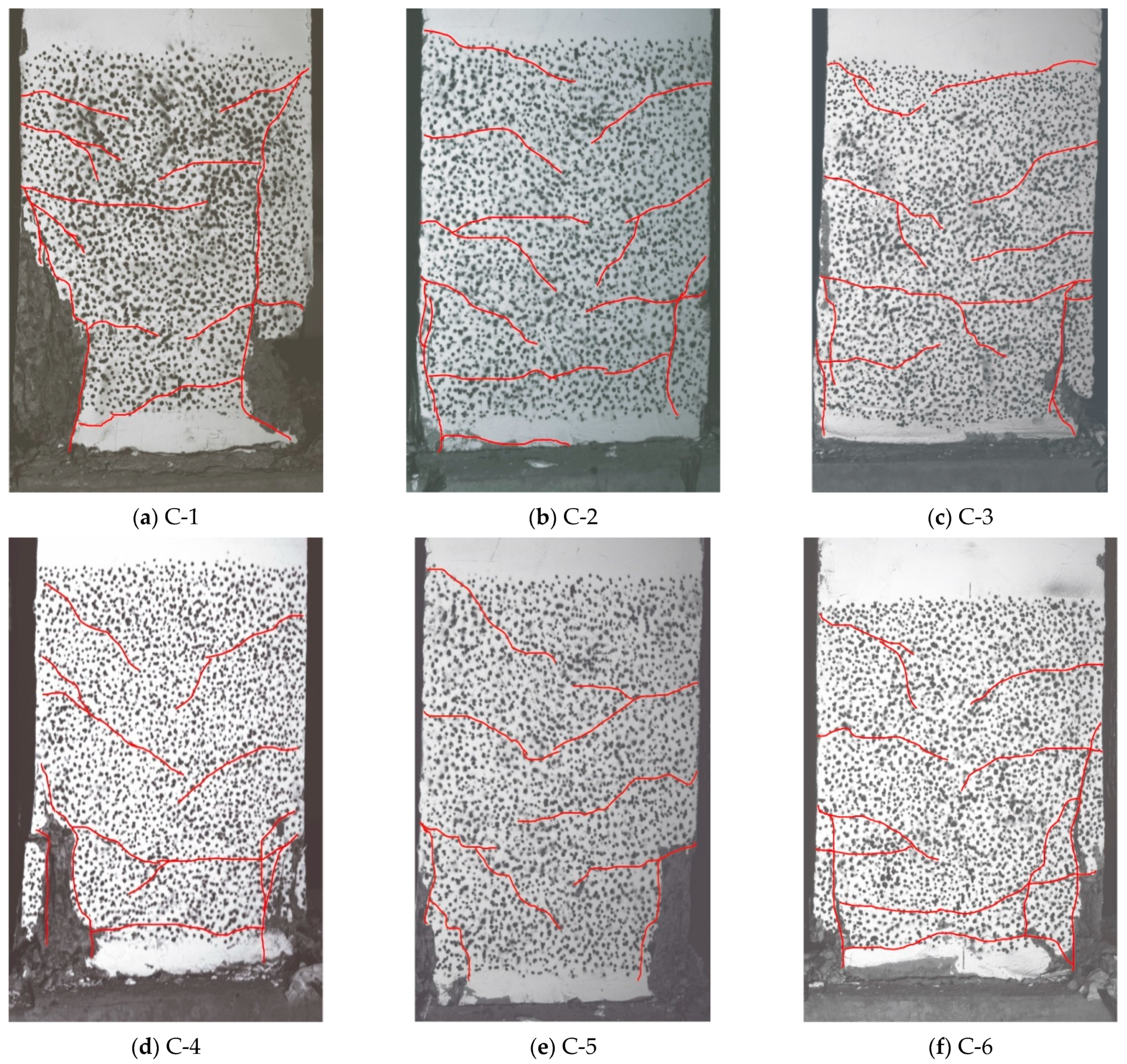
3.3. Destruction Patterns of SSCC

In the pseudo-static tests, all specimens mainly failed due to bending, with damage concentrated in the plastic hinge region (Figure 9). When the substitution rate was 20% and 40%, the damage height in the plastic hinge region was reduced. Compared to ordinary concrete, the steel slag sand concrete exhibited fewer and more evenly distributed cracks, likely due to the higher bond–slip strength of SSC. However, when the substitution rate exceeded 60%, the damage height increased, and vertical cracks appeared, leading to a more brittle failure mode.

3.4. Seismic Performance Analysis of SSC Columns

(1)
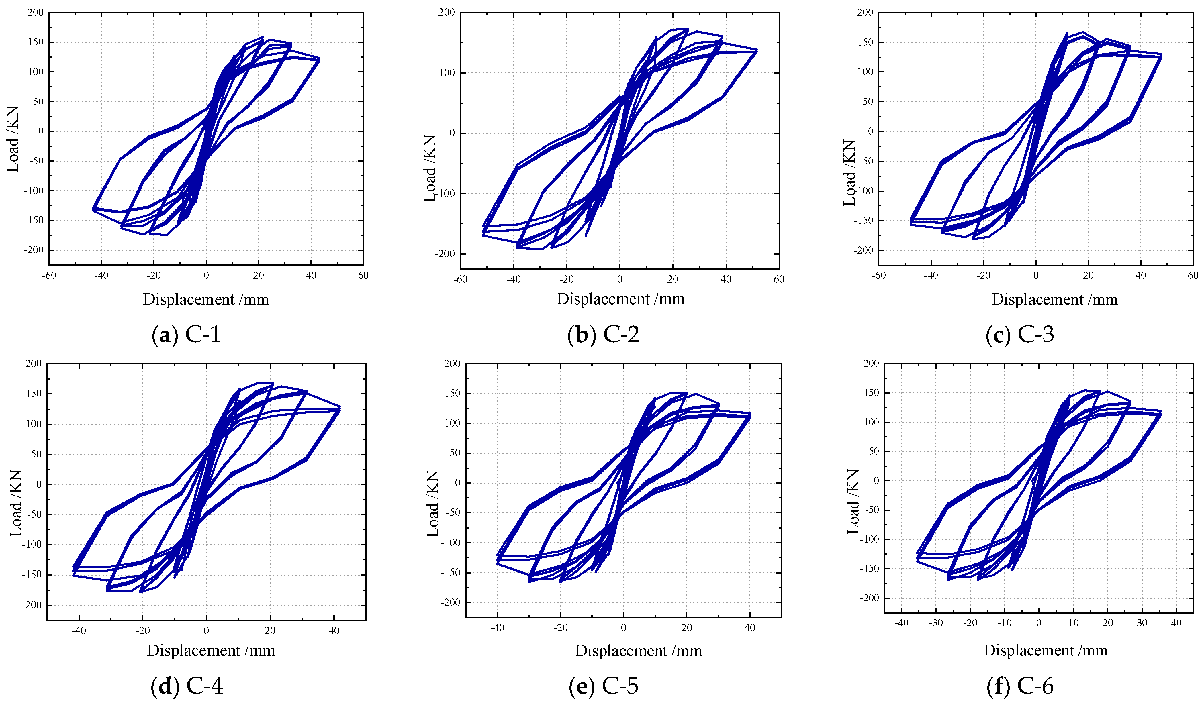
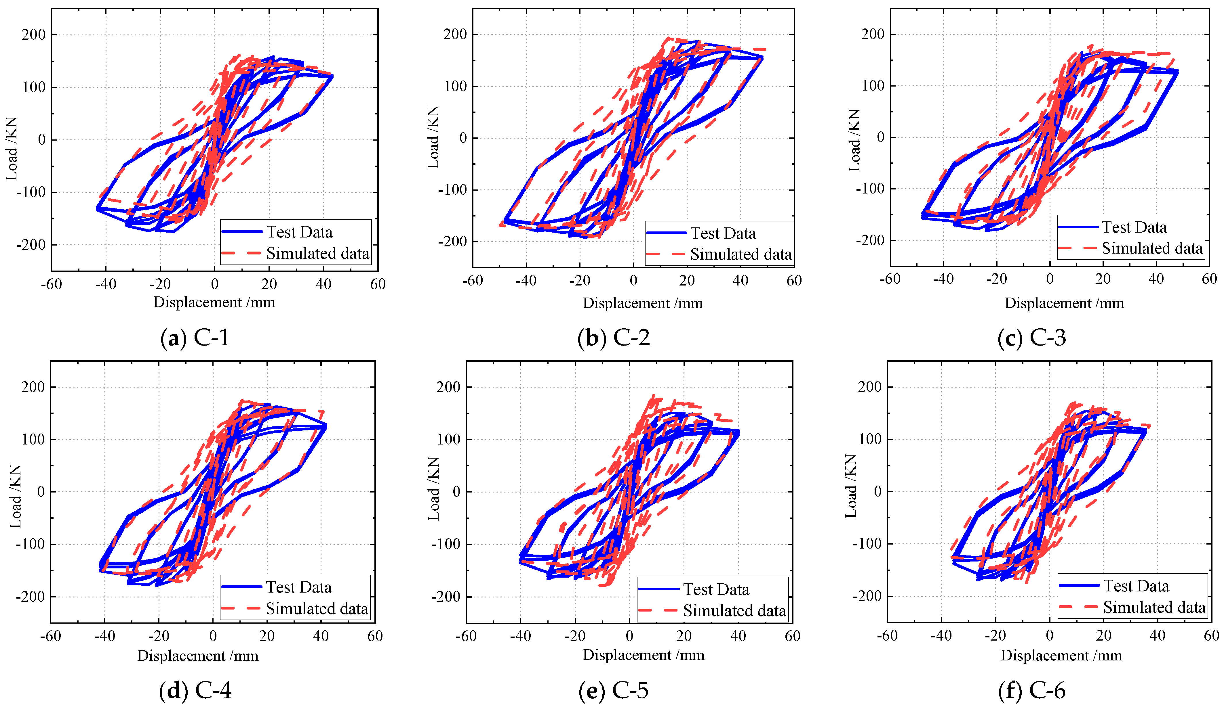
SSCC load–displacement hysteresis curve analysis
The load–displacement hysteresis curves, shown in Figure 10, illustrate the relationship between horizontal load and displacement, which is critical for seismic performance analysis. The results indicate that all specimens exhibited bow-shaped hysteresis curves with a pinching effect, mainly due to shear deformation and the opening and closing of diagonal cracks. As the loading–unloading cycles increased, the stiffness degradation became more noticeable. Compared to ordinary concrete, the steel slag sand concrete specimens showed fuller hysteresis curves and higher peak load capacities, especially at a 40% substitution rate. This improvement is attributed to the enhanced bond strength between the concrete and the reinforcement, leading to more efficient load transfer and better seismic performance.
(2)
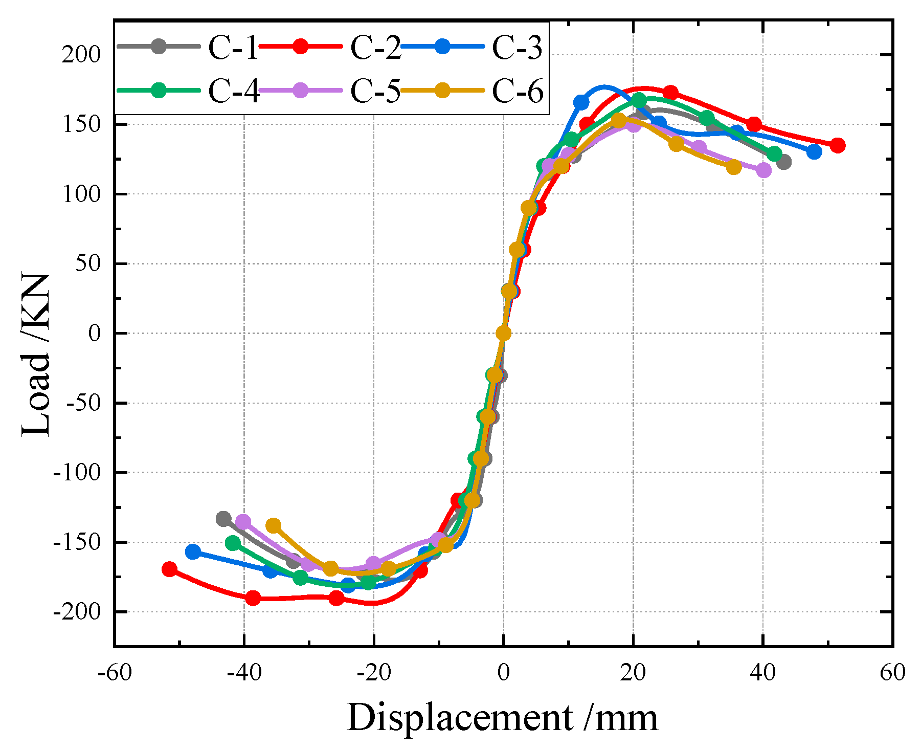
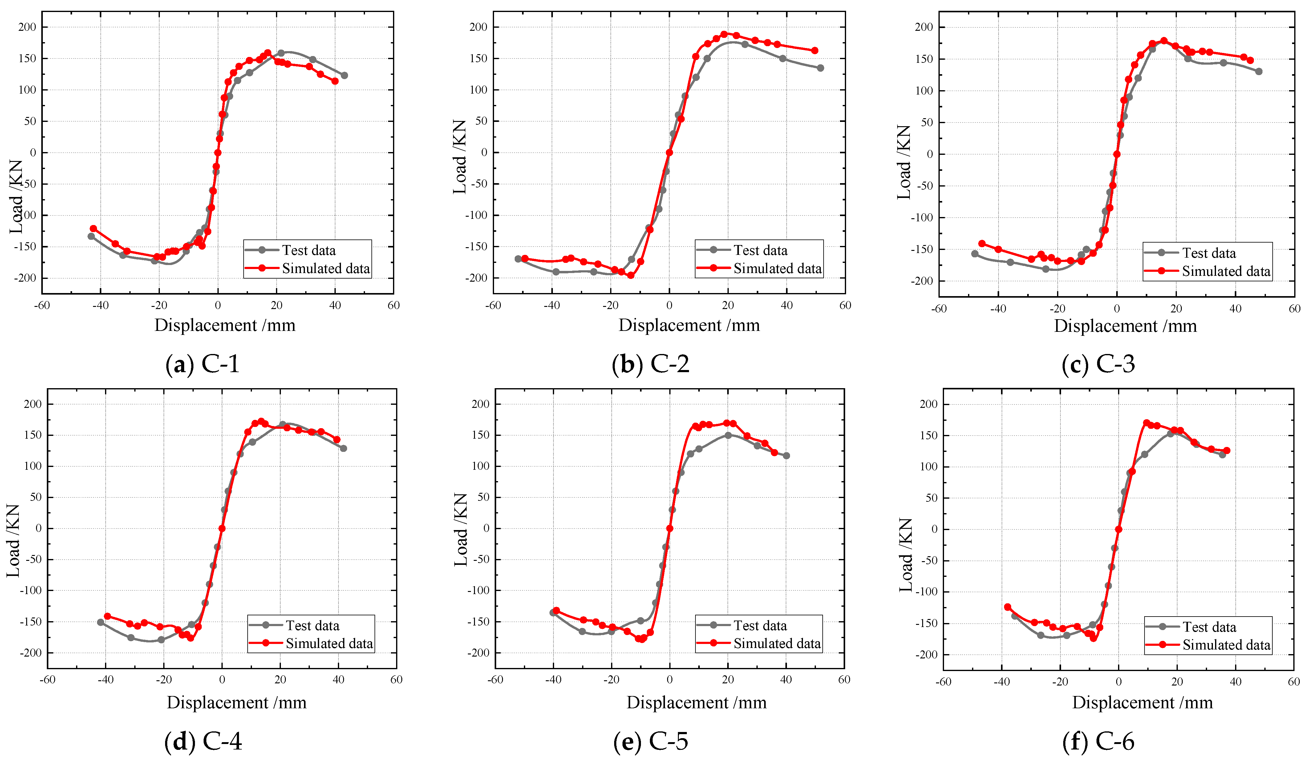
SSCC skeleton curve analysis
In this study, the equivalent elastoplastic energy method [40,41,42] and MATLAB’s (R2016a) incremental integration method were used to determine key performance parameters such as yield point, load capacity, yield displacement, and ultimate deformation. The skeleton curves (Figure 11) showed near symmetry, with slight discrepancies due to cumulative damage and installation errors. The average absolute values of the key parameters were used for analysis (Table 8). The results show that with steel slag sand replacement rates of 20%, 40%, and 60%, the SSCCs’ seismic performance improved compared to ordinary concrete. Before peak load, the skeleton curve’s slope (loading stiffness) was steeper, with peak loads increasing by 8.6%, 4.3%, and 5.1%. After peak load, the load decline was slower, and ultimate displacement was higher for 20% and 40% replacement rates, while 60% was similar to PC. However, when the replacement rate exceeded 60%, seismic performance declined. Moderate steel slag sand replacement improves seismic performance, while excessive replacement may be detrimental.
(3)
SSCC Ductility and Stiffness Degradation Analysis
This study, based on experimental results and in accordance with the Chinese standards GB50011-2010 [31] and JGJ/T101-2015 [33], selected the displacement ductility factor ( μ ) and the ultimate elastoplastic interlayer displacement angle ( θ u ) as key indicators for assessing the deformation capacity of structural components. The results in Table 9 show that all specimens had reasonable ductility factors, and the ultimate displacement angle meets code requirements. At 20% and 40% replacement rates, the steel slag sand concrete columns exhibited better ductility than ordinary concrete columns, with the most significant improvement at 40%, reaching 11.3%. However, at 80%, 60%, and 100% replacement rates, ductility decreased, especially affecting the ultimate displacement angle. Additionally, as seen in Figure 12, the SSC columns showed slower stiffness degradation compared to ordinary concrete columns, indicating better seismic performance.
(4)
SSCC energy dissipation analysis
The failure process of reinforced concrete columns under seismic loading involves energy absorption, conversion, dissipation, and release. The better the seismic performance of the specimen, the more energy it absorbs under seismic loading and the stronger its energy dissipation capacity. According to the Chinese standard GB50011-2010 [31], the equivalent viscous damping coefficient ( ζ e q ) can be used to characterize the energy dissipation capacity of the specimen. The calculated values of ζ e q for each specimen are shown in Figure 13. The values of ζ e q for all specimens ranged from 0.05 to 0.1 at yield and increased to between 0.15 and 0.26 at failure. The value of ζ e q increased slowly before yielding, while it rose rapidly after yielding. Furthermore, the effect of the steel slag sand replacement rate on ζ e q was minimal.
The experimental results show that a moderate replacement of steel slag sand improved the seismic performance of the concrete columns, enhancing the energy dissipation, ductility, and load-bearing capacity, especially at a 40% replacement rate. However, when the replacement exceeded 60%, both ductility and load-bearing capacity decreased, weakening the seismic performance. This can be attributed to the optimal bonding between cement paste and aggregates at moderate replacement levels. The high reactivity and expansive effects of steel slag sand reduce shrinkage cracks, improving concrete density and strength. However, at high replacement rates, increased water absorption and friction reduce workability, leading to voids and microcracks, which compromise seismic capacity.

3.5. Strain Analysis of SSCC Reinforcement

(1)
Strain analysis of longitudinal reinforcement
The longitudinal reinforcement strain gauges (J1 and J1 (1)) with the maximum deformation were chosen to monitor strain development and yielding, as shown in Figure 14. All specimens showed yielding of the reinforcement, but the strain development varied. The strain on the negative side was generally higher than on the positive side, likely due to the loading sequence, where the concrete cracked on the tensile side during positive loading, allowing it to bear more load during negative loading. Compared to ordinary concrete, the steel slag sand concrete exhibited slower strain development, especially at 20% and 40% replacement rates. This indicates that steel slag sand helps to slow down strain development in the longitudinal reinforcement.
(2)
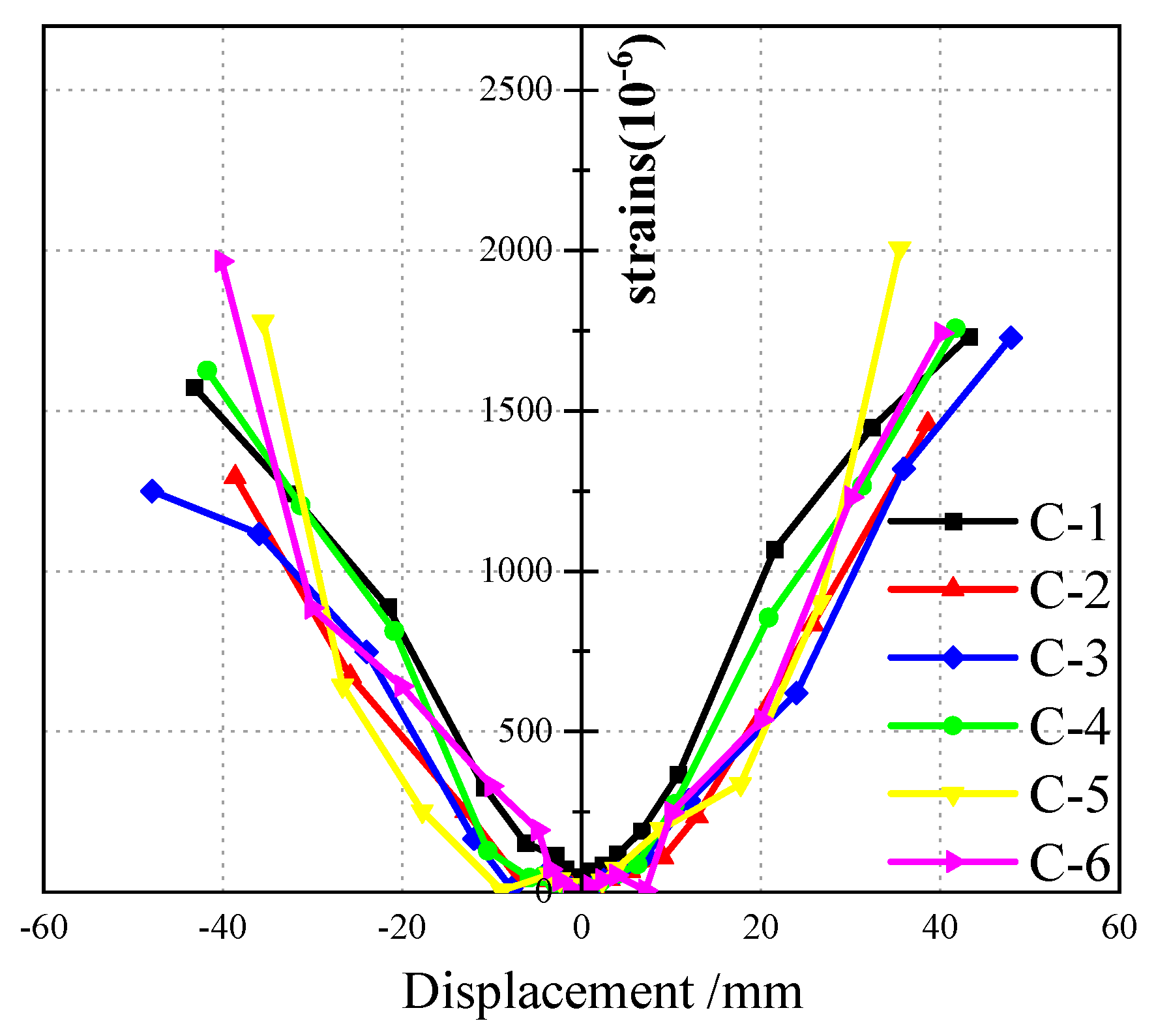
Strain analysis of hoop reinforcement
The strain development of the stirrup gauges (G1 and G1(1)), where the maximum strain occurred during loading, is shown in Figure 15. The results reveal that the steel slag sand replacement similarly slowed the stirrup strain development, akin to its effect on the longitudinal reinforcement. This may be attributed to the expansive nature of steel slag sand concrete, which applies pre-stress to the reinforcement, enhancing stirrup confinement, improving crack resistance, and reducing deformation under external loads. This has been corroborated in experiments on steel tube–steel slag concrete [43].

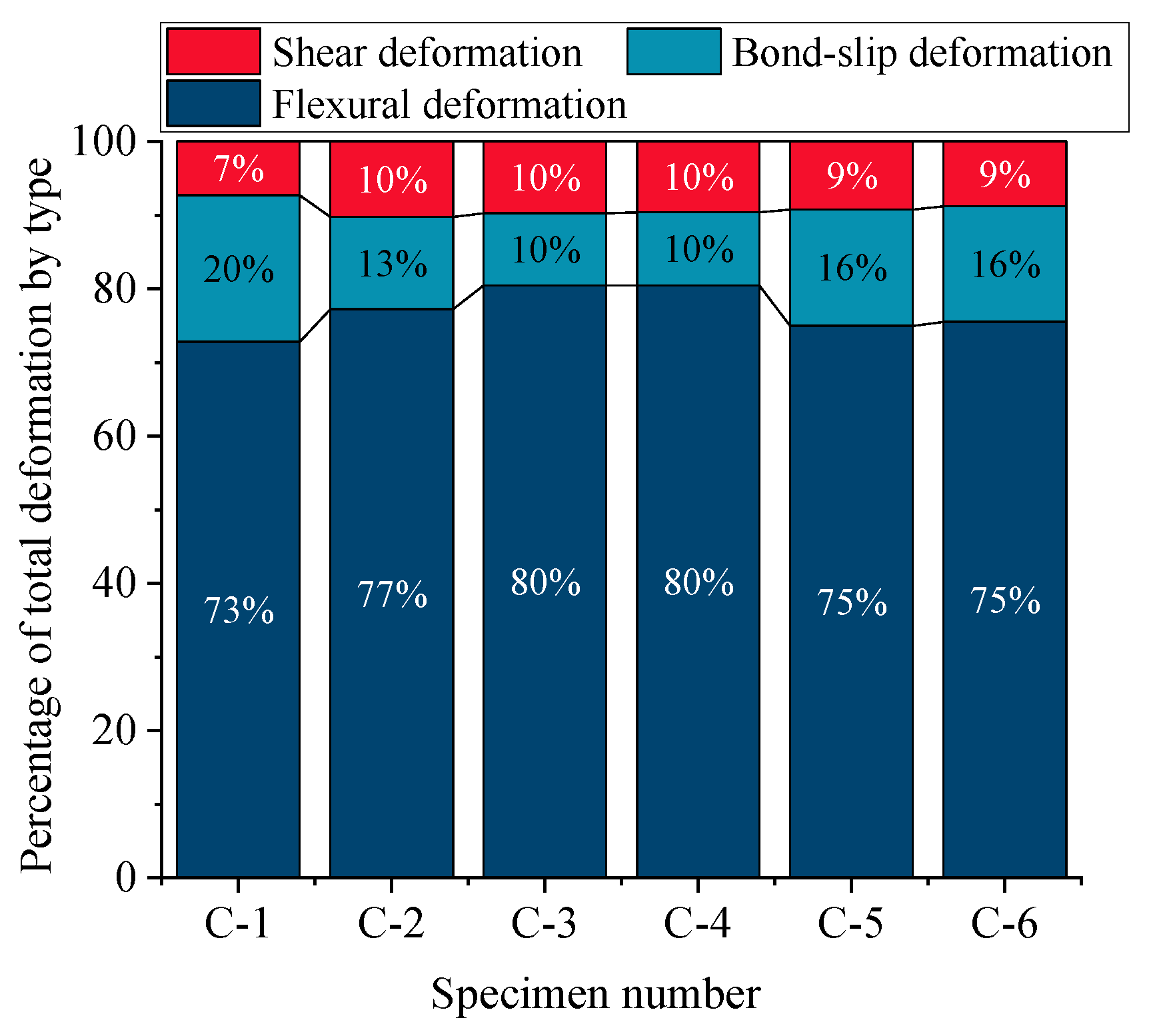
3.6. Deformation Analysis of Plastic Hinge Region

In the experiment, displacement gauges and the DIC strain measurement system were employed to measure the displacement in the plastic hinge region of SSC columns. The results, shown in Figure 16, indicate a minimal discrepancy between the two methods. However, the displacement gauges showed limitations in capturing small displacements before the yield point and during compression. In contrast, the DIC system provided higher accuracy, capable of measuring displacements even during small elastic deformations. Despite the DIC system’s inability to measure during the final loading cycle due to concrete spalling, its overall precision was superior to that of the displacement gauges. Consequently, data from the DIC system were used for the analysis of the plastic hinge displacement in the SSC columns.
The total displacement Δ of reinforced concrete column specimens consists of bending deformation Δf, shear deformation Δs, and bond–slip deformation Δslip. The displacement components at each stage were calculated using the displacement gauge measurements and Formulas (1) to (4) as follows:
Δ f = ( H 0.5 l ) ( L 5 L 6 ) / h
Δ s = L 7 L 8 2 cos α = ( L 7 L 8 ) a 2 + h 2 2 h
Δ slip = L 9 H / h 0
Δ = Δ f + Δ s + Δ slip ,   Δ f = Δ Δ
where l represents the displacement gauge height in the plastic hinge region, approximated as the column height h = 400 mm; a denotes the plastic hinge region width (a = 400 mm); Δ’ is the total displacement within the plastic hinge region; Δf refers to the elastic deformation and bending caused by cracks outside the plastic hinge region. The experimental results in Table 10 indicate that bending deformation predominated in the plastic hinge region, contributing 65% to 77% of the total deformation, followed by bond–slip deformation (5% to 18%) and shear deformation (4% to 10%), as shown in Figure 17. The plastic hinge region accounted for 82% to 95% of the total column deformation, as shown in Figure 18, indicating that it is the primary deformation zone, consistent with the observed bending failure of the columns.
The experimental results demonstrate that, compared to plain concrete, the proportion of bond–slip deformation in the plastic hinge region of the steel slag sand concrete specimens decreased, while bending deformation increased. This is attributed to the enhanced bond strength, which improved the interaction between the rebar and concrete, leading to a more uniform stress distribution in the rebar and more efficient transfer of tensile stress, thereby increasing bending deformation.
The experimental results align with existing literature and further deepen the understanding of steel slag aggregate’s mechanisms. At a 20–40% replacement ratio, compressive strength increased by 17.7–18.5%, validating the conclusions of Faleschini et al. [22] and Guo et al. [5] on optimal replacement rates and performance enhancement. Steel slag sand improved bond strength by 14.7%, surpassing the improvement seen with coarse aggregates, as reported by Chen et al. [15], indicating a more significant effect of fine steel slag on the steel–concrete interface. Additionally, the bond–slip curves showed more stable residual strength compared to Le Minh et al.’s [44] findings on recycled aggregate concrete. In terms of seismic performance, existing studies have shown that steel slag aggregate can effectively improve the load carrying capacity, ductility, and energy dissipation capacity of concrete columns, and similar effects were verified in this study by improving the interfacial bond. Overall, steel slag aggregate enhances both mechanical and seismic performance, supporting its feasibility and advantages in structural engineering.

4. Finite Element Analysis

4.1. Material Eigenmodel

(1)
Concrete material principal structure
The nonlinear behavior of concrete in the finite element model was defined using the concrete damaged plasticity (CDP) model, which offers robust numerical convergence and is widely applied in the simulation of both static and dynamic responses of cementitious materials [44]. The CDP model requires user-defined uniaxial stress–strain laws to describe the material’s hardening and softening under tension and compression.
For steel slag concrete (SSC), the uniaxial compressive stress–strain relationship was modeled using the modified constitutive model proposed by Z. Ren [45], tailored for steel slag aggregate concrete. The expression is given as:
y = a x + ( 3 2 a ) x 2 + ( a 2 ) x 3 , 0 x < 1 x b ( x 1 ) 2 + x x 1
where y = fc/fu, with fc representing the applied compressive stress and fu the peak compressive stress; x = ε / ε u , with ε representing the strain corresponding to the applied compressive stress and ε u the peak compressive strain; a is the parameter of the ascending section, a = a0 + 0.00292R, and b is the parameter of the descending section, b = b0 + 0.00344R, in which a0 and b0 refer to the shape-control parameters of the uniaxial compressive stress–strain curve of ordinary concrete; and R is the replacement rate of steel slag sand.
For the uniaxial tensile stress–strain relationship of SSC, this study adopted the concrete tensile model specified in the Chinese code GB50010-2010 [30] to estimate the tensile behavior observed in the experiments:
y = 1.2 x 0.2 x 6 x 1 x α t ( x 1 ) 1.7 + x x > 1
where y = σt/ft and x = ε / ε u , with σ t representing the applied tensile stress and ft the axial tensile strength of concrete, f t = 0.395 f c 0.55 , and ε representing the strain corresponding to the applied tensile stress; α t is the descending segment parameter, α t = 0.312 f t 2 ; and ε t is the peak tensile strain, ε t = 65 × 10 6 f t 0.54 .
Stiffness degradation of SSC resulting from compressive crushing and tensile cracking was characterized by plastic damage variables, computed using Sidiroff’s energy equivalence principle [46]. The corresponding formulations are as follows:
d = 1 σ E 0 ε
where σ is the true stress, E0 is the initial modulus of elasticity, and ε is the true strain. Moreover, the computed damage variables must exhibit a monotonically increasing trend to ensure physical consistency. The parameters for the yield function and flow potential in the model are summarized in Table 11 [47].
(2)
Reinforcing material principal structure
The constitutive model for steel reinforcement was defined using a bilinear model, with parameters such as yield strength and ultimate strength derived from the values in Table 5.
(3)
SSC bond–slip ontological relationship
Previous research has proposed several segmented bond–slip models to describe the interaction between concrete and reinforcement [44,45]. Following this approach, the present study developed a segmented bond–slip model for steel slag sand concrete (SSC). The ascending branch of the bond–slip curve exhibits an infinite initial slope at s = 0 and transitions smoothly to the descending branch, a feature similar to the continuous curve model proposed by Gao Danying [48]. This model, characterized by smooth curves and clearly defined characteristic points, has been widely applied to basalt concrete and fiber-reinforced polymer bars [39,40,41]. However, its descending branch expression is relatively complex and tends to underestimate residual bond stress, which affects the fitting accuracy in the softening stage. To improve model applicability, the Guo Zhenhai model was introduced to describe the descending branch, as it has been validated for effectiveness in recycled aggregate concrete [49]. Following this approach, the present study incorporated the steel slag sand (SSA) replacement ratio as a key influencing parameter and establishes a quantitative relationship between the model parameters and the replacement ratio through regression analysis. This enhanced the predictive capability and engineering applicability of the model for the bond–slip behavior of SSC. The specific expressions are as follows:
τ = τ u ( s s u ) 1 / 2 s s u , 0 s s u < 1 τ u s / s u b ( s / s u 1 ) 2 + s / s u s s u 1
b = b 0 ( 0.48 + 8.6 r 18.6 r 2 + 12.6 r 3 )
where b represents the descending segment parameter for SSC, while b0 denotes the descending segment parameter for PC. The relationship between b/b0 and the steel slag sand replacement ratio r is shown in Figure 19. Normalized sensitivity analysis indicates that when the steel slag sand replacement ratio (r) is below 0.7, the system exhibits moderate to low sensitivity. Within this range, the response of parameter b to r is mild, ensuring a favorable balance between material tunability and stability. Therefore, r ≤ 0.7 is recommended as the optimal design range. When r exceeds 0.7, b increases sharply with r (Figure 20), resulting in a steeper descending branch of the bond–slip curve, increased brittleness, and reduced ductility. This trend is consistent with both the stress–strain behavior and the observed reduction in ductility in the hysteresis curves of SSCCs at higher replacement ratios. Figure 21 compares the correlation coefficients of the Gao Danying model, the Xiao model [50], and the model presented in this study. The results indicate that the model proposed in this study has a mean correlation coefficient closer to 1 and a smaller range, further confirming its ability to effectively describe the bond–slip relationship between steel slag sand concrete and reinforcement.

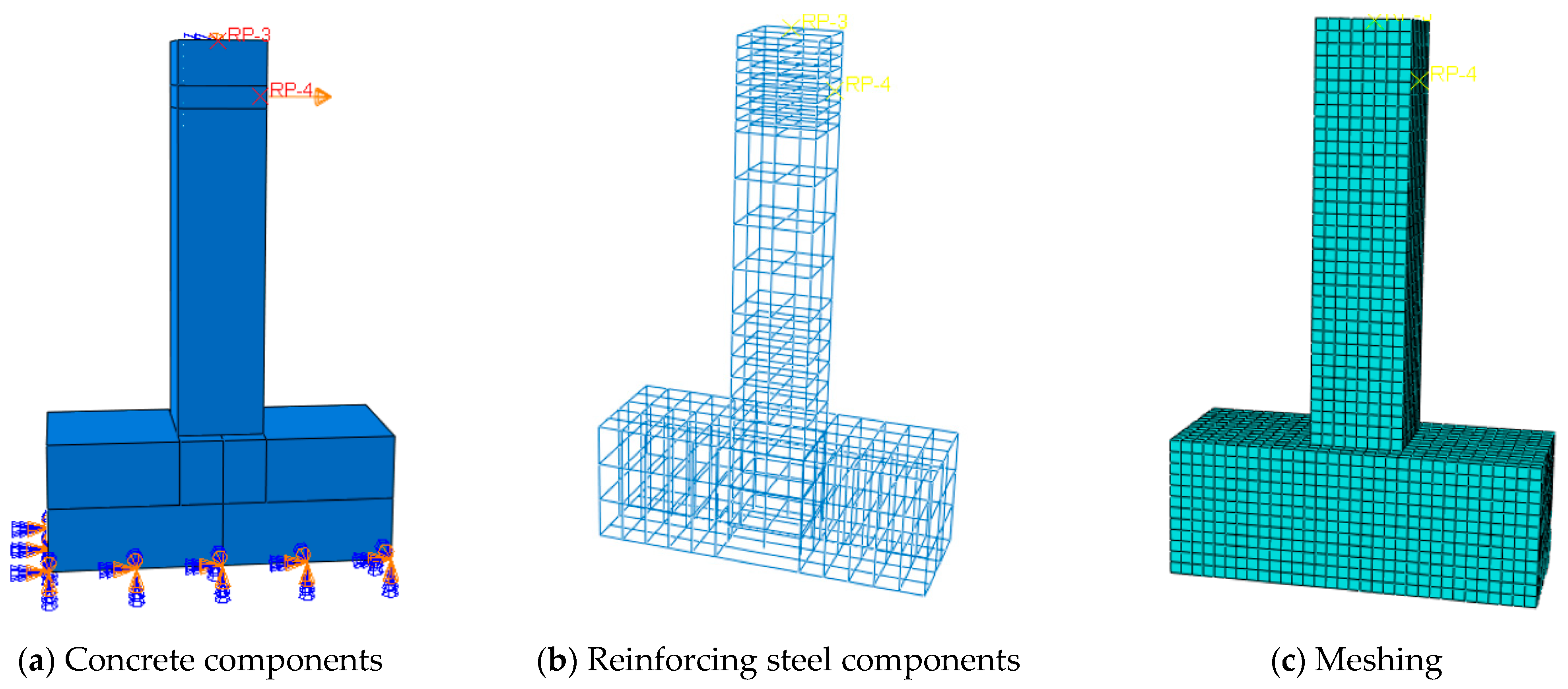
4.2. Finite Element Modeling

The finite element model of the specimen shown in Figure 2 was constructed with dimensions and boundary conditions matching the experimental setup, as depicted in Figure 22. Reinforcement was modeled using line elements, integrated with concrete units. Node correspondence between the reinforcement and the concrete was established using Excel (2021), and the INP file was modified to insert nonlinear springs, simulating the bond–slip behavior between the two materials [48,51]. The spring properties were defined according to the bond–slip model proposed herein. The concrete was modeled with C3D8R solid elements, while the reinforcement was modeled as T3D2 truss elements during meshing. In the simulation, the column base was fully fixed, and axial pressure and horizontal forces were applied in accordance with the experimental conditions. Since the experiment employed force–displacement hybrid loading control, and the finite element software supports only force or displacement loading, displacement corresponding to the pre-yield force was used for the loading scheme. The specific loading procedure is shown in Figure 23.

4.3. Simulation Results and Analysis

Finite element analysis of SSCCs under cyclic loading was performed, and the load-displacement curves at the column base were extracted, as shown in Figure 24 and the skeleton curve, as shown in Figure 25. The simulation results closely align with the experimental curves, confirming that the model accurately captures the force characteristics of the specimen. To further verify the accuracy of the finite element model, the correlation coefficient (R2) between the simulated and experimental load–displacement curves was calculated. The results showed good agreement between the model predictions and experimental data, with R2 values ranging from 0.88 to 0.96, approaching 1.0 (Figure 26). This indicates that the finite element model can accurately capture the hysteretic cure and stiffness degradation characteristics of the specimens. However, discrepancies in the hysteresis loops under positive and negative loading were observed in the experiments. The discrepancies between experimental and simulation results mainly stem from material model simplifications, finite element assumptions, and test conditions. First, the current model does not fully capture the complex hysteretic cure of steel slag concrete under cyclic loading, and further refinement with experimental data is needed. Second, simplifications in bond–slip modeling and reinforcement representation reduce accuracy; future work should adopt solid elements and cohesive elements for improved realism. Finally, pauses and slower loading during tests allow for more crack development and material degradation; it also led to discrepancies between the experimental and simulated backbone curves, as shown in Figure 25. In contrast, regression analyses were performed to quantitatively examine the relationships between the bond strength, ductility coefficient, and equivalent viscous damping coefficient. The resulting correlation curves are presented in Figure 27 and Figure 28. The analysis demonstrates that an increase in bond strength generally enhanced both the ductility and the energy dissipation capacity of the SSCCs. However, excessively high bond strength adversely affected seismic performance. Moderate bond strength is beneficial as it promotes appropriate bond–slip behavior, enabling the reinforcement to undergo sufficient yielding and plastic deformation under cyclic seismic loading, and thereby improving ductility and energy dissipation capacity. Conversely, overly strong bonding can induce stress concentrations at the steel–concrete interface, increasing the likelihood of brittle failure and consequently reducing the structural ductility [52,53]. Finally, the damage distribution and stress concentration in the concrete, as shown in Figure 29 and Figure 30, indicate that both damage and stress were concentrated in the plastic hinge region. The closer the location to the plastic hinge, the greater the damage and stress concentration. This distribution matches the experimental observations, further validating the accuracy of the finite element model in predicting the structural response.

5. Conclusions

This study investigated the seismic performance of steel slag aggregate concrete columns (SSCCs) with varying steel slag sand replacement ratios (0% to 100%) through experiments and finite element analysis, focusing on the influence of bond strength. The key conclusions are as follows:
(1)
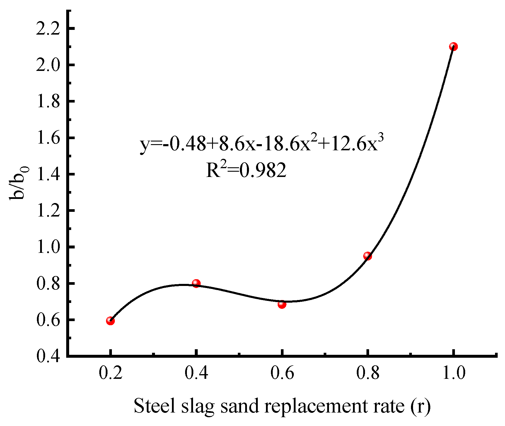
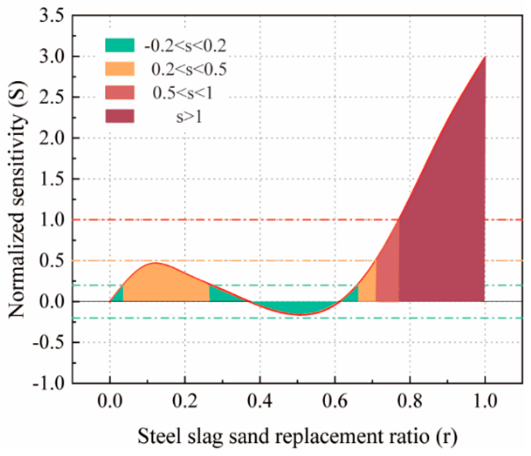
As the steel slag sand substitution rate increases, the cube compressive strength (fcu), axial compressive strength (fc), and bond strength of the concrete initially increase and then decrease. Optimal mechanical properties are observed at substitution rates of 20–40%. Notably, the improvement in bond strength is more pronounced than in fcu and fc.
(2)
The incorporation of steel slag sand markedly improves the seismic performance of the columns. Compared with conventional plain concrete (PC) columns, the SSCCs demonstrate superior seismic characteristics under cyclic loading. The experimental results reveal that at a 40% replacement ratio, the SSCCs exhibit an 11.3% increase in energy dissipation capacity, a 10% reduction in bond–slip deformation within the plastic hinge region, and a 9% improvement in flexural deformation capacity relative to PC. Furthermore, the SSCCs exhibit more stable and fuller hysteresis loops, higher ductility coefficients, and larger ultimate drift ratios, all indicative of enhanced energy dissipation capability and seismic resilience.
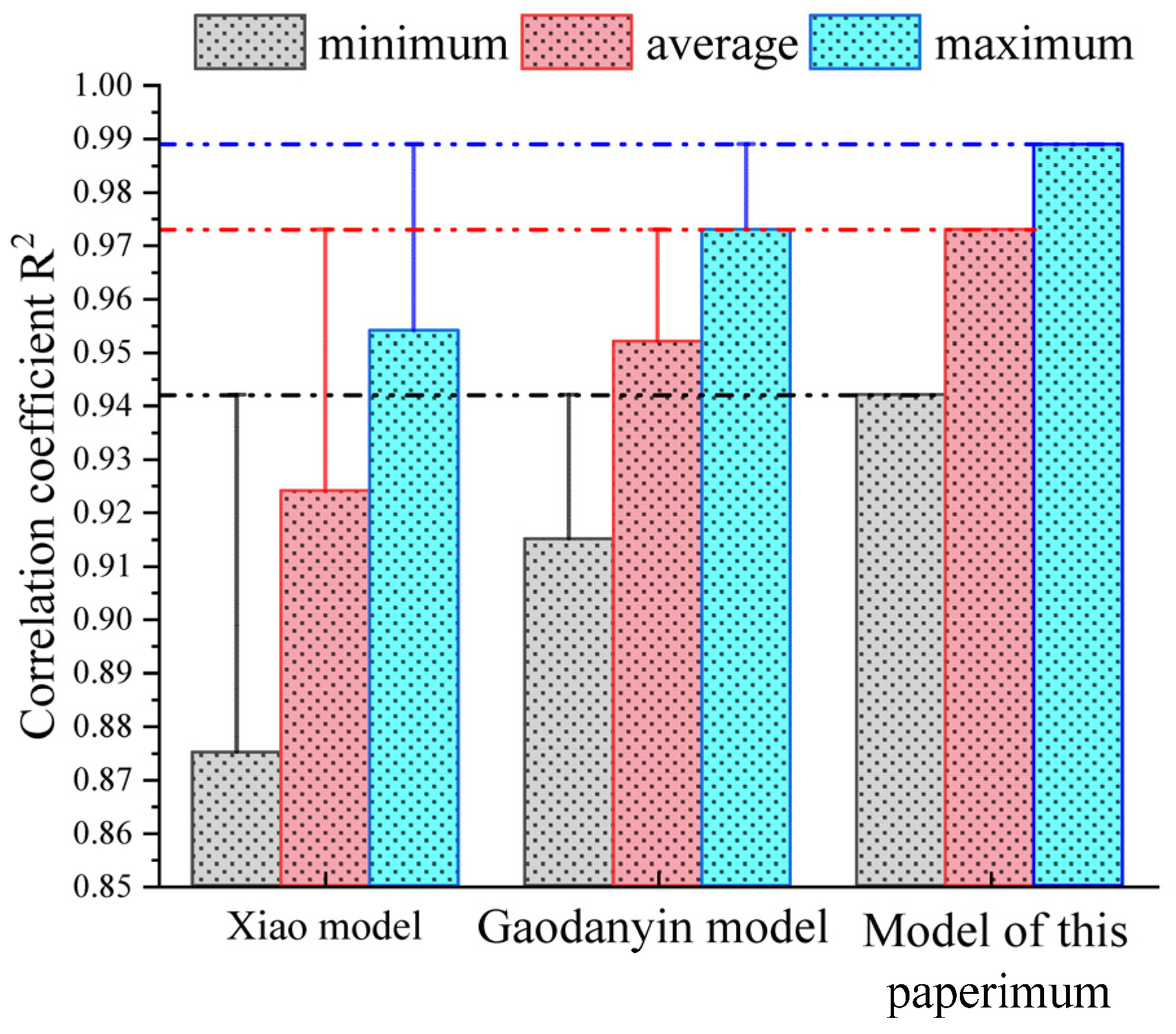
(3)
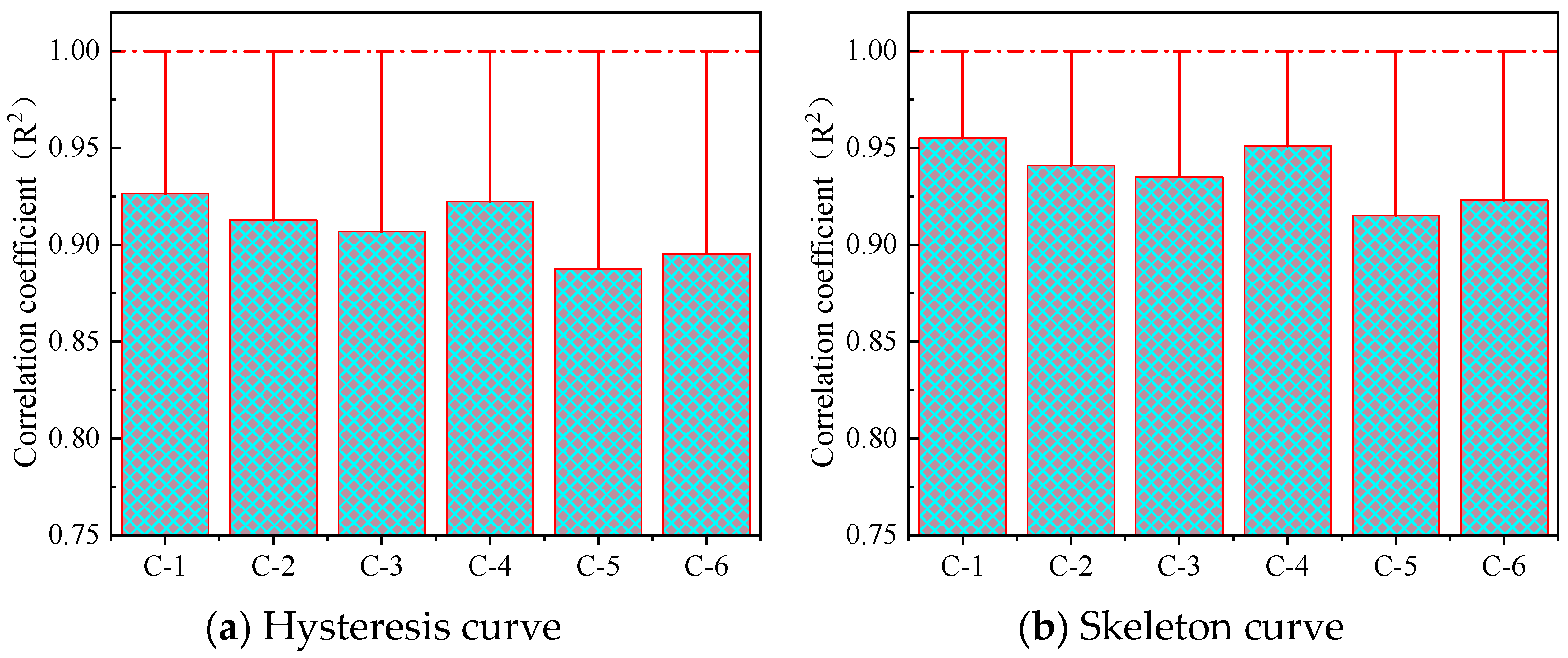
The study proposes the bond–slip relationship between SSC and reinforcing steel and develops a finite element (FE) model to simulate the seismic response of SSCCs. The model incorporates bond–slip effects to accurately capture the load–displacement behavior under cyclic loading. Although the model does not fully reproduce the pinching effect observed in the experimental hysteresis curves, its predictions of load capacity and ductility show strong agreement with experimental results, validating the effectiveness of the FE approach for evaluating and designing the seismic performance of steel slag aggregate concrete structures.
Overall, this research advances the understanding of steel slag aggregate as a sustainable material for enhancing the seismic performance of reinforced concrete structures. By integrating experimental evidence with numerical modeling, the study presents a comprehensive methodological framework that offers a theoretical foundation for the design of sustainable and earthquake-resilient concrete columns. Nevertheless, further investigations are warranted to evaluate the long-term durability and environmental implications of SSCCs in practical engineering applications.

Author Contributions

T.Z.: conceptualization, methodology, writing—original draft, funding acquisition. Q.J.: visualization, formal analysis, funding acquisition. D.Z.: resources, funding acquisition. S.L.: software. X.L.: data curation. All authors have read and agreed to the published version of the manuscript.

Funding

This work was supported by the Key Laboratory of Hydraulic Engineering Security and Water Disasters Prevention in 2022 of Xinjiang (No. ZDSYS-YJS-2022-17), the 2024 Xinjiang Uygur Autonomous Region Graduate Education Innovation Program (XJ2024G109), and the 2024 Henan Provincial Science and Technology Research and Development Project (242102321023).

Data Availability Statement

The authors believe that all relevant data are already included in the present article. However, if more details are needed, they are available upon request from the corresponding author.

Conflicts of Interest

The authors declare no conflicts of interest.

References

  1. Gencel, O.; Karadag, O.; Oren, O.H.; Bilir, T. Steel slag and its applications in cement and concrete technology: A review. Constr. Build. Mater. 2021, 283, 122783. [Google Scholar] [CrossRef]
  2. Ye, G.; Yuen, K.-V.; Jin, Q.; Zhou, M.; Yin, C.; Jiang, Q.; Zhao, S.; Su, W. Evaluation method for uniformity of steel slag concrete aggregate based on improved YOLOv8. J. Build. Eng. 2024, 98, 111046. [Google Scholar] [CrossRef]
  3. Dong, Q.; Wang, G.; Chen, X.; Tan, J.; Gu, X. Recycling of steel slag aggregate in portland cement concrete: An overview. J. Clean. Prod. 2021, 282, 124447. [Google Scholar] [CrossRef]
  4. Wang, C.; Ye, G.; Jin, Q.; Zhou, Z.; Hu, D.; Wei, Y. The uniaxial compressive stress-strain relations of steel slag fine aggregate concrete under steam curing. Constr. Build. Mater. 2025, 459, 139820. [Google Scholar] [CrossRef]
  5. Guo, Y.; Xie, J.; Zheng, W.; Li, J. Effects of steel slag as fine aggregate on static and impact behaviours of concrete. Constr. Build. Mater. 2018, 192, 194–201. [Google Scholar] [CrossRef]
  6. Zhou, Z.; Jin, Q.; Hu, D.; Zhu, L.; Li, Z.; Su, W. Long-term volume stability of steel slag sand mortar and concrete. Case Stud. Constr. Mater. 2025, 22, e04179. [Google Scholar] [CrossRef]
  7. Wang, Q.; Yan, P.; Yang, J.; Zhang, B. Influence of steel slag on mechanical properties and durability of concrete. Constr. Build. Mater. 2013, 47, 1414–1420. [Google Scholar] [CrossRef]
  8. Lai, M.; Lin, Y.; Jin, Y.; Fei, Q.; Wang, Z.; Ho, J. Uni-axial behaviour of steel slag concrete-filled-steel-tube columns with external confinement. Thin-Walled Struct. 2023, 185, 110562. [Google Scholar] [CrossRef]
  9. Lu, L.; Zhang, T.; Liang, T.; Ren, Q. Axial compressive behavior of circular concrete-filled steel tube stub columns with steel slag coarse aggregate. Structures 2023, 51, 1893–1905. [Google Scholar] [CrossRef]
  10. Pang, Y.; Cai, L.; Ouyang, H.; Zhou, X. Seismic performance assessment of different fibers reinforced concrete columns using incremental dynamic analysis. Constr. Build. Mater. 2019, 203, 241–257. [Google Scholar] [CrossRef]
  11. Bu, S.; Yu, F.; Chen, T.; Fang, Y.; Qin, Y. Experimental study on seismic behavior of circular steel tube confined reinforced self-stressing steel slag concrete columns. Struct. Concr. 2023, 24, 1102–1117. [Google Scholar] [CrossRef]
  12. Lu, L.; Liang, T.; Zhang, T.; Ren, Q.; Wang, Q.; Wang, S. Axial compressive behaviors of circular steel slag concrete-filled steel tube slender columns. Struct. Concr. 2023, 24, 6953–6972. [Google Scholar] [CrossRef]
  13. Cai, R.; Zhang, J.; Liu, Y.; Tao, X. Seismic behavior of recycled concrete columns reinforced with ultra-high-strength steel bars. Eng. Struct. 2023, 279, 115633. [Google Scholar] [CrossRef]
  14. Liu, K.; Yan, J.; Zou, C. A pilot experimental study on seismic behavior of recycled aggregate concrete columns after freeze-thaw cycles. Constr. Build. Mater. 2018, 164, 497–507. [Google Scholar] [CrossRef]
  15. Chen, Z.; Jing, C.; Xu, J.; Zhang, X. Seismic performance of recycled concrete-filled square steel tube columns. Earthq. Eng. Eng. Vib. 2017, 16, 119–130. [Google Scholar] [CrossRef]
  16. Baili, J.; Raza, A.; Azab, M.; Ali, K.; El Ouni, M.H.; Haider, H.; Farooq, M.A. Experiments and predictive modeling of optimized fiber-reinforced concrete columns having FRP rebars and hoops. Mech. Adv. Mater. Struct. 2023, 30, 4913–4932. [Google Scholar] [CrossRef]
  17. Liu, J.; Yu, B.; Wang, Q. Application of steel slag in cement treated aggregate base course. J. Clean. Prod. 2020, 269, 121733. [Google Scholar] [CrossRef]
  18. Gong, W.; Chen, Q.; Miao, J. Bond behaviors between copper slag concrete and corroded steel bar after exposure to high temperature. J. Build. Eng. 2021, 44, 103312. [Google Scholar] [CrossRef]
  19. Montgomery, D.; Wang, G. Instant-chilled steel slag aggregates in concrete—Strength related properties. Cem. Concr. Res. 1991, 21, 1083–1091. [Google Scholar] [CrossRef]
  20. Olonade, K.; Kadiri, M.; Aderemi, P. Performance of Steel Slag as Fine Aggregate in Structural Concrete. Nig. J. Technol. 2015, 34, 452. [Google Scholar] [CrossRef]
  21. Yu, F.; Chen, T.; Niu, K.; Wang, S.; Kong, Z.; Fang, Y. Study on Bond-Slip Behaviors of Self-Stressing Steel Slag Concrete-Filled Steel Tube. KSCE J. Civ. Eng. 2020, 24, 3309–3319. [Google Scholar] [CrossRef]
  22. Faleschini, F.; Santamaria, A.; Zanini, M.A.; José, J.-T.S.; Pellegrino, C. Bond between steel reinforcement bars and Electric Arc Furnace slag concrete. Mater. Struct. 2017, 50, 170. [Google Scholar] [CrossRef]
  23. Hui, S. Mechanical Properties and Volumetric Stability of Steel Slag Concrete. Master’s Thesis, Inner Mongolia University of Science and Technology, Baotou, China, 2023. [Google Scholar]
  24. Sun, Y. Mechanical Properties and Microstructure of Steel Slag Concrete. Master’s Thesis, Guangzhou University, Guangzhou, China, 2022. [Google Scholar]
  25. Yu, F.; Qin, Y.; Yao, C.; Bu, S.; Fang, Y. Experimental investigation on the seismic behavior of self-stressing steel slag CFST column. Struct. Concr. 2022, 23, 1492–1507. [Google Scholar] [CrossRef]
  26. Alkhawaldeh, S. FE Modelling of the Bond-Slip Behaviour and Its Effects on the Seismic Performance of RC Framed Structures. Ph.D. Thesis, Loughborough University, Loughborough, UK, 2019. [Google Scholar]
  27. Qin, X.C.; Ding, M.B.; Lu, J.H.; Liu, D.; Hao, Y. Quasi-static test study on railway gravity piers with unbonded steel bars. J. Nat. Disasters 2022, 31, 134–141. [Google Scholar]
  28. Pan, S.; Chen, D.; Chen, X.; Ge, G.; Su, D.; Liu, C. Experimental Study on the Workability and Stability of Steel Slag Self-Compacting Concrete. Appl. Sci. 2020, 10, 1291. [Google Scholar] [CrossRef]
  29. GB/T 228.1-2010; General Administration of Quality Supervision, Inspection and Quarantine of the People’s Republic of China. Tensile Testing of Metallic Materials—Part 1: Methods of Test at Room Temperature. China Standards Press: Beijing, China, 2011.
  30. GB/T 50010-2010; Ministry of Housing and Urban-Rural Development of the People’s Republic of China, Code for Design of Concrete Structures. China Architecture & Building Press: Beijing, China, 2010.
  31. GB 50011-2010; Ministry of Housing and Urban-Rural Development of the People’s Republic of China, Code for Seismic Design of Buildings. China Architecture & Building Press: Beijing, China, 2010.
  32. JGJ 55-2011; Ministry of Housing and Urban-Rural Development of the People’s Republic of China. Code for Design of Concrete Mixes. China Architecture & Building Press: Beijing, China, 2011.
  33. JGJ/T 101-2015; Ministry of Housing and Urban-Rural Development of the People’s Republic of China, Standard for Seismic Isolation Design of Buildings. China Architecture & Building Press: Beijing, China, 2015.
  34. Zhao, X.; Wu, Y.-F.; Leung, A.; Lam, H.F. Plastic Hinge Length in Reinforced Concrete Flexural Members. Procedia Eng. 2011, 14, 1266–1274. [Google Scholar] [CrossRef]
  35. Pokhrel, M.; Bandelt, M.J. Plastic hinge behavior and rotation capacity in reinforced ductile concrete flexural members. Eng. Struct. 2019, 200, 109699. [Google Scholar] [CrossRef]
  36. Xue, G.; Fu, Q.; Xu, S. Macroscopic mechanical properties and microstructure characteristics of steel slag fine aggregate concrete. J. Build. Eng. 2022, 56, 104742. [Google Scholar] [CrossRef]
  37. Pan, Z.; Zhou, J.; Jiang, X. Investigating the effects of steel slag powder on the properties of self-compacting concrete with recycled aggregates. Constr. Build. Mater. 2019, 200, 570–577. [Google Scholar] [CrossRef]
  38. Gu, X.; Wang, H.; Zhu, Z.; Liu, J.; Xu, X.; Wang, Q. Synergistic effect and mechanism of lithium slag on mechanical properties and microstructure of steel slag-cement system. Constr. Build. Mater. 2023, 396, 131768. [Google Scholar] [CrossRef]
  39. Zghair, H.H. Optimization of mechanical characteristics of cement mortar incorporating hybrid nano-sustainable powders. J. Mech. Behav. Mater. 2024, 33, 20240008. [Google Scholar] [CrossRef]
  40. Valikhani, A.; Jahromi, A.J.; Mantawy, I.M.; Azizinamini, A. Experimental evaluation of concrete-to-UHPC bond strength with correlation to surface roughness for repair application. Constr. Build. Mater. 2020, 283, 117753. [Google Scholar] [CrossRef]
  41. Lee, H.-S.; Noguchi, T.; Tomosawa, F. Evaluation of the bond properties between concrete and reinforcement as a function of the degree of reinforcement corrosion. Cem. Concr. Res. 2002, 32, 1313–1318. [Google Scholar] [CrossRef]
  42. Yuan, T.; Mao, Y. A review of pinch analysis techniques and extended application in power systems. Renew. Sustain. Energy Rev. 2024, 202, 114684. [Google Scholar] [CrossRef]
  43. He, H.; Cheng, S.; Chen, Y. Earthquake damage assessment model based on differential ratio of elastic–plastic dissipated energy. Bull. Earthq. Eng. 2022, 20, 2719–2749. [Google Scholar] [CrossRef]
  44. Le Minh, H.; Khatir, S.; Wahab, M.A.; Cuong-Le, T. A concrete damage plasticity model for predicting the effects of compressive high-strength concrete under static and dynamic loads. J. Build. Eng. 2021, 44, 103239. [Google Scholar] [CrossRef]
  45. Ren, Z.; Li, D. Uniaxial compressive behavior study of normal-strength concrete using waste steel slag aggregate through laboratory tests and numerical simulation. J. Build. Eng. 2024, 85, 108720. [Google Scholar] [CrossRef]
  46. Xiao, Y.; Chen, Z.; Zhou, J.; Leng, Y.; Xia, R. Concrete plastic-damage factor for finite element analysis: Concept, simulation, and experiment. Adv. Mech. Eng. 2017, 2017, 168781401771964. [Google Scholar] [CrossRef]
  47. Mohemmi, M.; Broujerdian, V.; Rajaeian, P. An Equivalent Method for Bar Slip Simulation in Reinforced Concrete Frames. Int. J. Civ. Eng. 2020, 18, 851–863. [Google Scholar] [CrossRef]
  48. Gao, D.; Xie, J.; Li, C. Basic issues of bond behavior of fiber-reinforced polymer bars in concrete. J. Zhengzhou Univ. (Eng. Sci. Ed.) 2002, 23, 1–5. [Google Scholar]
  49. Bai, G.; Liu, B. Nonlinear finite element analysis of bond-slip performance of recycled aggregate concrete filled circular steel tube. J. Adhes. Sci. Technol. 2019, 33, 1294–1319. [Google Scholar] [CrossRef]
  50. Xiao, J.; Falkner, H. Bond behaviour between recycled aggregate concrete and steel rebars. Constr. Build. Mater. 2007, 21, 395–401. [Google Scholar] [CrossRef]
  51. Zou, J.-F.; Wu, Q.-H. Three-dimensional elastoplastic analysis of strain-softening surrounding rock based on the non-linear bond-slip relationship considering hydraulic-mechanical coupling. Eur. J. Environ. Civil Eng. 2024, 28, 3567–3586. [Google Scholar] [CrossRef]
  52. Cao, S.; Wang, Y.; Wang, J. Influence of bond-slip behavior on seismic performance of reinforced concrete columns. Eng. Struct. 2020, 207, 110254. [Google Scholar]
  53. Saatcioglu, M.; Razvi, S.R. Strength and ductility of confined concrete. J. Struct. Eng. 1992, 118, 1590–1607. [Google Scholar] [CrossRef]
Figure 1. Specimen fabrication.
Buildings 15 01769 g001
Figure 2. Steel slag sand concrete column design details.
Buildings 15 01769 g002
Figure 3. Test loading device diagram.
Buildings 15 01769 g003
Figure 4. Loading system.
Buildings 15 01769 g004
Figure 5. Deformation measurement of the steel slag sand concrete columns.
Buildings 15 01769 g005
Figure 6. Measurement of deformation in the plastic hinge region.
Buildings 15 01769 g006
Figure 7. Strain gauge arrangement details.
Buildings 15 01769 g007
Figure 8. SSC bond–slip curve.
Buildings 15 01769 g008
Figure 9. SSC column destruction pattern.
Buildings 15 01769 g009
Figure 10. Specimen hysteresis curve.
Buildings 15 01769 g010
Figure 11. Specimen skeleton curve.
Buildings 15 01769 g011
Figure 12. Stiffness degradation curve.
Buildings 15 01769 g012
Figure 13. Equivalent viscous damping factor.
Buildings 15 01769 g013
Figure 14. Longitudinal reinforcement strain.
Buildings 15 01769 g014
Figure 15. Strain of the hoop.
Buildings 15 01769 g015
Figure 16. Comparison of DIC and displacement gauge measurements.
Buildings 15 01769 g016
Figure 17. Percentage of each type of deformation in the deformation of the plastic hinge zone.
Buildings 15 01769 g017
Figure 18. Plastic hinge zone deformation as a percentage of total deformation.
Buildings 15 01769 g018
Figure 19. Relationship between model parameters b and r.
Buildings 15 01769 g019
Figure 20. Normalized sensitivity analysis results of b with respect to r.
Buildings 15 01769 g020
Figure 21. Comparison of correlation coefficients of different models.
Buildings 15 01769 g021
Figure 22. Simulation of seismic performance of concrete columns.
Buildings 15 01769 g022
Figure 23. Loading regime for the finite element models.
Buildings 15 01769 g023
Figure 24. Comparison of hysteresis curves from the quasi-static tests and finite element simulations for the Steel Slag Sand Concrete Columns.
Buildings 15 01769 g024
Figure 25. Comparison of skeleton curves from the quasi-static testing and finite element simulation of the Steel Slag Sand Concrete Columns.
Buildings 15 01769 g025
Figure 26. Correlation coefficient between the simulated and experimental curves.
Buildings 15 01769 g026
Figure 27. The relationship between the bond strength and the ductility coefficient.
Buildings 15 01769 g027
Figure 28. The relationship between the bond strength and the equivalent viscous damping coefficient.
Buildings 15 01769 g028
Figure 29. Concrete damage distribution.
Buildings 15 01769 g029
Figure 30. Rebar stress distribution.
Buildings 15 01769 g030
Table 1. Chemical composition of the cement.
SiO2Al2O3Fe2O3CaOMgOSO3Na2OK2OLoss
24.964.883.5860.971.190.950.130.782.56
Table 2. Physical properties of the cement.
Cement GradeSpecific Gravity (g/cm3)Blaine Surface Area (m2/kg)Water Requirement of Standard Consistency (%) Setting Time (min)Flexural Strength (MPa)Compressive Strength (MPa)
Initial SettingFinal Setting3 d28 d3 d28 d
42.5R3.1334627.81472085.17.326.749.8
Table 3. Physical properties of the aggregates.
AggregatesApparent Relative
Density (kg/m3)
Bulk Density
(Kg/m3)
Water
Absorption (%)
Crush
Value (%)
Fineness
Modulus
Natural stone258814380.728.74
Natural sand265915960.977.252.71
Steel slag sand332219251.24.372.86
Table 4. The main chemical composition of the steel slag sand.
Chemical
Composition
SiO2CaOMgOFe2O3P2O5Al2O3MnOf-CaOOther
Content (%)12.9742.638.4420.34.330.940.732.37.36
Table 5. HRB400 rebar performance parameters.
Diameter
(mm)
Area (mm2)Yield Strength (MPa)Yield Strain (με)Ultimate
Strength (MPa)
Poisson’s
Ratio
NominalMeasured
850.2750.6841319155900.3
16201.1211.0545421856210.3
Table 6. Mixture details.
Sample IDCement (kg/m3)NAS
(kg/m3)
Steel Slag Sand (kg/m3)NAC
(kg/m3)
Water (kg/m3)WRA (kg/m3)
C-1375852-10171693.00
C-2681.6207.573.225
C-3511.2415.153.45
C-4340.8622.723.675
C-5170.4830.293.90
C-6-1037.874.125
Table 7. Mechanical properties of the concrete.
Sample IDfcu, 7d
(MPa)
fcu, 28d (MPa)fc
(MPa)
fts, 28d
(MPa)
τ
(MPa)
fc/fcu
PC27.736.128.23.2610.340.78
SSC-2033.542.833.23.5614.070.78
SSC-4029.739.330.93.8313.480.79
SSC-6029.937.028.42.8810.320.77
SSC-8029.035.026.82.6510.480.76
SSC-10028.035.627.62.269.590.80
Table 8. Specimen skeleton curve calculation results.
Calculation
Parameters
Load DirectionC-1C-2C-3C-4C-5C-6
Peak load
(KN)
Positive152.7176.5165.6167.3149.8152.9
Negative166.4198.3181.1178.0165.7169.1
Averages159.5185.4173.4172.7157.8161.0
Yield load
(KN)
Positive129.0151.6140.9140.1126.3126.1
Negative143.2167.9159.1154.5143.9151.0
Averages136.1159.8150.0147.3135.1138.6
Yield displacement
(mm)
Positive11.313.010.410.810.29.4
Negative10.312.611.311.49.68.7
Averages10.812.810.8511.19.99.1
Ultimate load
(KN)
Positive123.0134.8130.3128.8117.1119.4
Negative133.3169.5157.0151.0135.4138.2
Averages128.2152.2143.7139.9126.3128.8
Ultimate displacement
(mm)
Positive43.251.547.941.840.135.5
Negative43.251.547.941.840.135.5
Averages43.251.447.941.840.135.5
Table 9. Calculation results of the specimen ductility coefficient and ultimate displacement angle.
Sample IDLoad
Direction
Yield
Displacement (mm)
Ultimate
Displacement
(mm)
Ductility
Coefficient
AverageUltimate
Displacement
Angle (%)
Average (%)
C-1Positive11.343.23.83.951.2001.200
Negative10.343.24.11.200
C-2Positive13.051.54.04.051.4221.427
Negative12.651.54.11.431
C-3Positive10.447.94.64.41.3311.331
Negative11.347.94.21.331
C-4Positive10.841.83.93.81.1601.160
Negative11.441.83.71.160
C-5Positive10.239.63.83.951.1151.114
Negative9.639.64.11.114
C-6Positive9.435.53.83.90.9870.987
Negative8.735.54.10.987
Table 10. Seismic column deformation test results.
Sample IDCharacteristic PointΔf/mm
( Δ f / Δ ) %
Δ s /mm
( Δ s / Δ ) %
Δ slip /mm
( Δ slip / Δ ) %
Δ / Δ
%
C-1Yield point7.02 (65.4)0.66 (6.2)1.29 (10.1)83.2
Peak point15.04 (66.3)1.45 (6.4)3.87 (15.2)89.4
Limit point29.46 (68.2)3.02 (7.1)8.21 (17.7)94.2
C-2Yield point8.62 (67.2)1.03 (8.0)1.26 (9.8)84.8
Peak point18.36 (67.2)2.45 (9.1)2.73 (10.9)86.2
Limit point35.54 (69.3)4.73 (9.2)5.77 (11.2)89.4
C-3Yield point8.56 (71.5)0.71 (6.0)0.63 (5.3)82.8
Peak point16.2 (72.7)1.62 (7.2)1.53 (6.8)85.8
Limit point35.46 (74.5)4.26 (8.9)4.26 (10.9)91.8
C-4Yield point7.64 (72.2)0.70 (6.8)0.72 (6.9)86.9
Peak point13.72 (72.4)1.32 (7.3)1.36 (7.5)90.2
Limit point30.02 (73.7)3.59 (8.6)3.72 (11.9)94.2
C-5Yield point6.82 (68.8)0.87 (8.7)0.96 (9.6)86.3
Peak point12.24 (69.8)1.61 (9.2)2.19 (12.5)91.5
Limit point29.02 (72.3)3.33 (8.3)5.69 (14.2)94.8
C-6Yield point5.57 (69.3)0.35 (4.2)0.87 (9.8)87.8
Peak point9.49 (72.5)1.65 (4.2)1.95 (12.3)88.2
Limit point24.99 (72.1)2.92 (5.4)5.19 (13.8)93.2
Table 11. Plastic parameters of the concrete in the CDP model.
DilationEccentricityfcb/fc0Kμ
300.11.160.00670.0001
Disclaimer/Publisher’s Note: The statements, opinions and data contained in all publications are solely those of the individual author(s) and contributor(s) and not of MDPI and/or the editor(s). MDPI and/or the editor(s) disclaim responsibility for any injury to people or property resulting from any ideas, methods, instructions or products referred to in the content.

