
Synergistic Effects of Alkali Activator Dosage on Carbonation Resistance and Microstructural Evolution of Recycled Concrete: Insights from Fractal Analysis and Optimal Threshold Identification

Abstract
1. Introduction
2. Materials and Methods
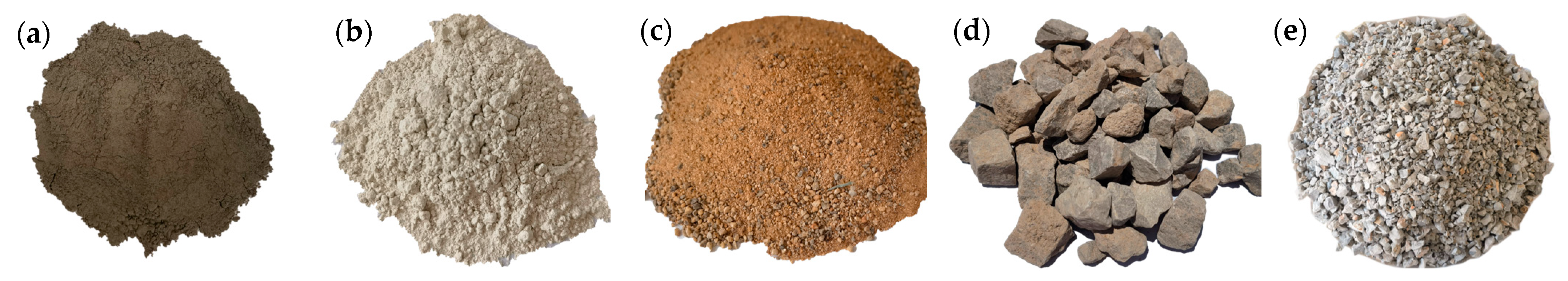
2.1. Materials
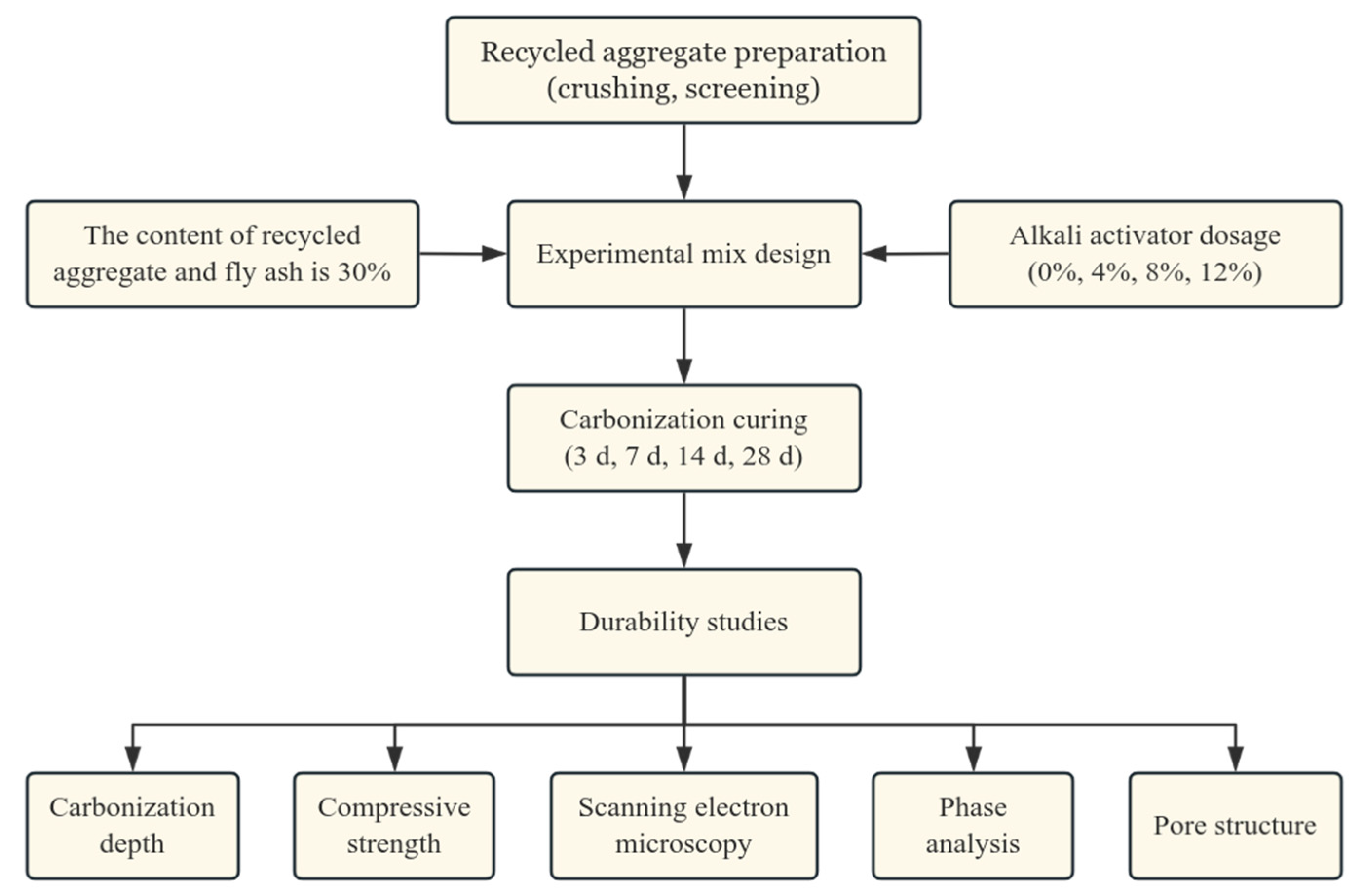
2.2. Mix Proportion
2.3. Carbonation Test Method
2.4. Microstructure Characterization Methods
- The pore structure was assumed to exhibit statistical self-similarity within the analyzed scale range (50 nm to 50 μm).
- Pores smaller than the SEM resolution threshold (50 nm) were not captured in the imaging process.
- Fractal dimension (FD) values derived from 2D images may underestimate the true 3D pore complexity; however, averaging across multiple imaging planes was applied to mitigate this effect.
2.5. Flowchart
3. Results and Discussion
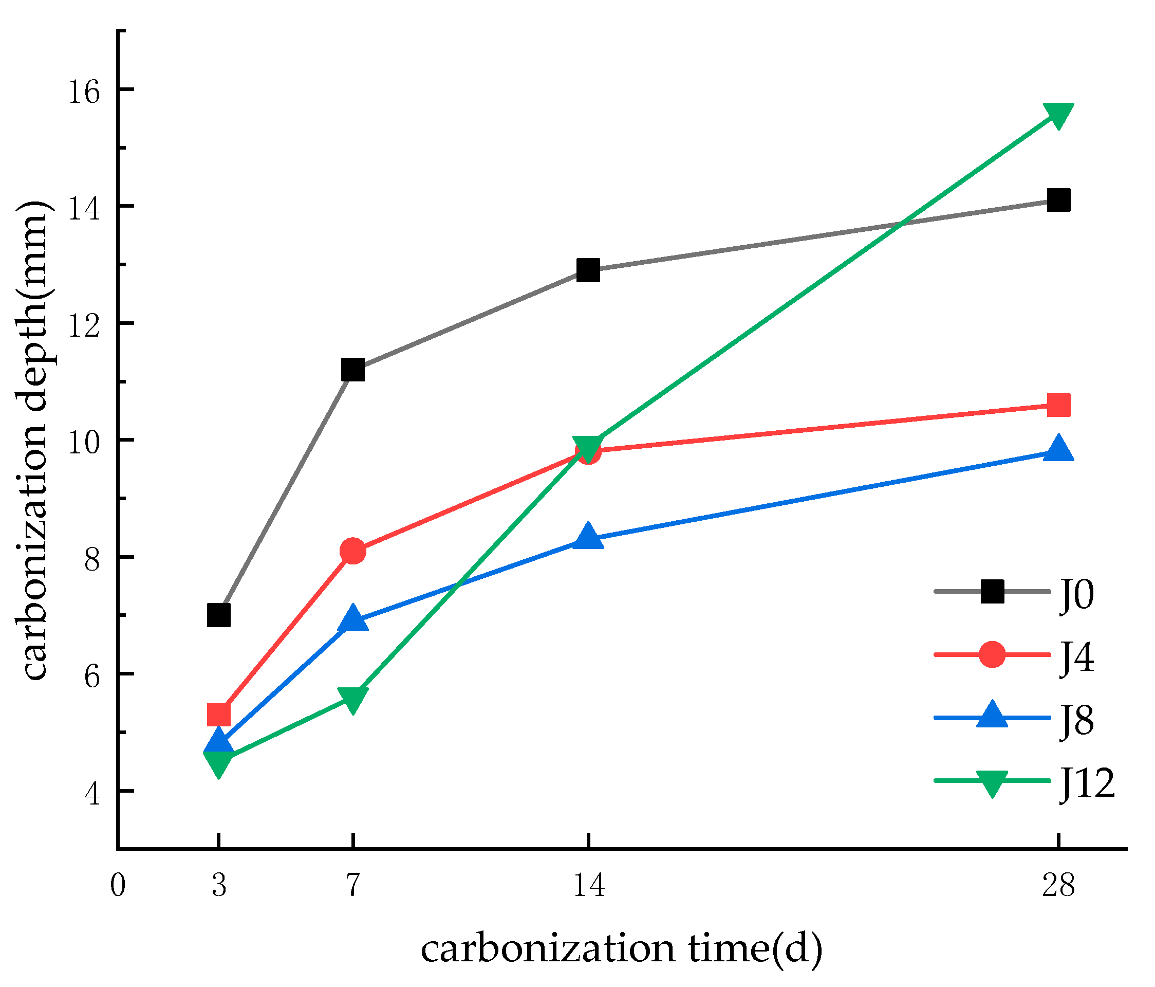
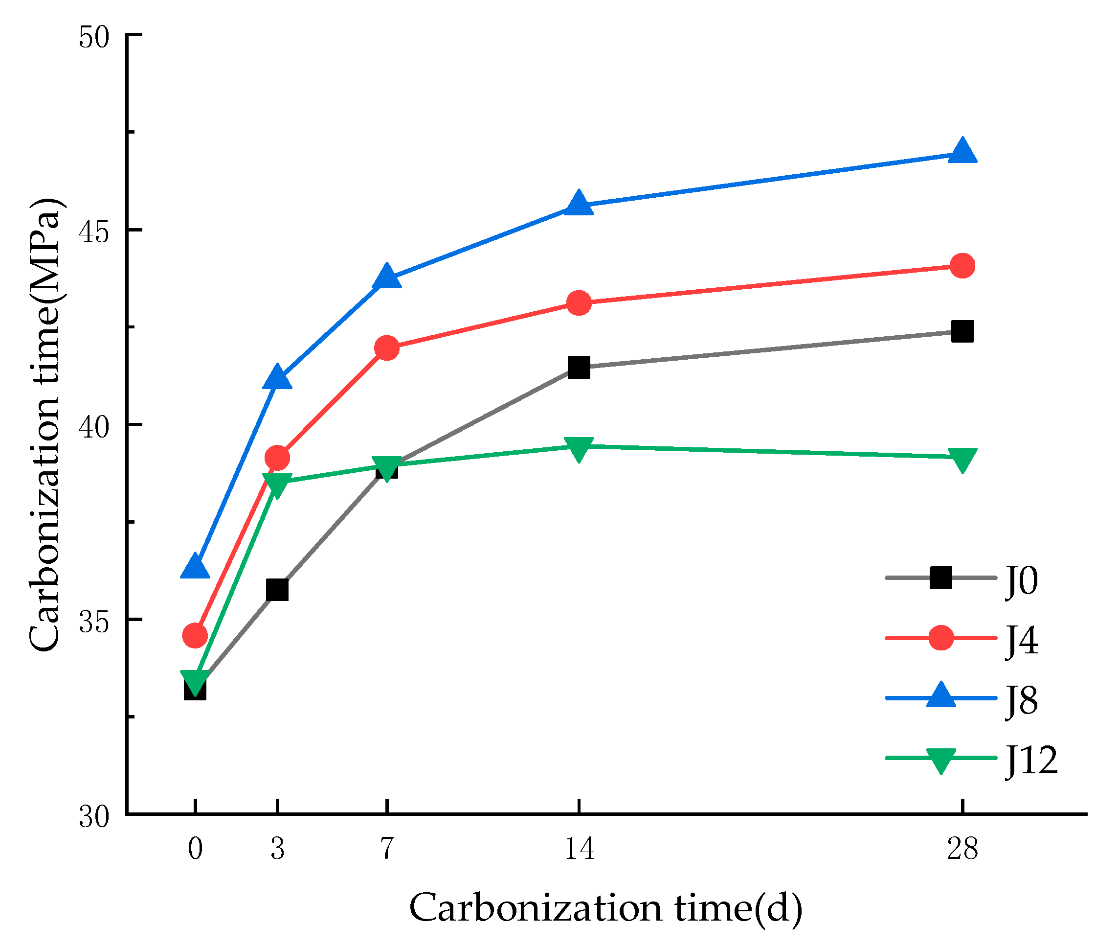
3.1. Carbonation Depth and Compressive Strength
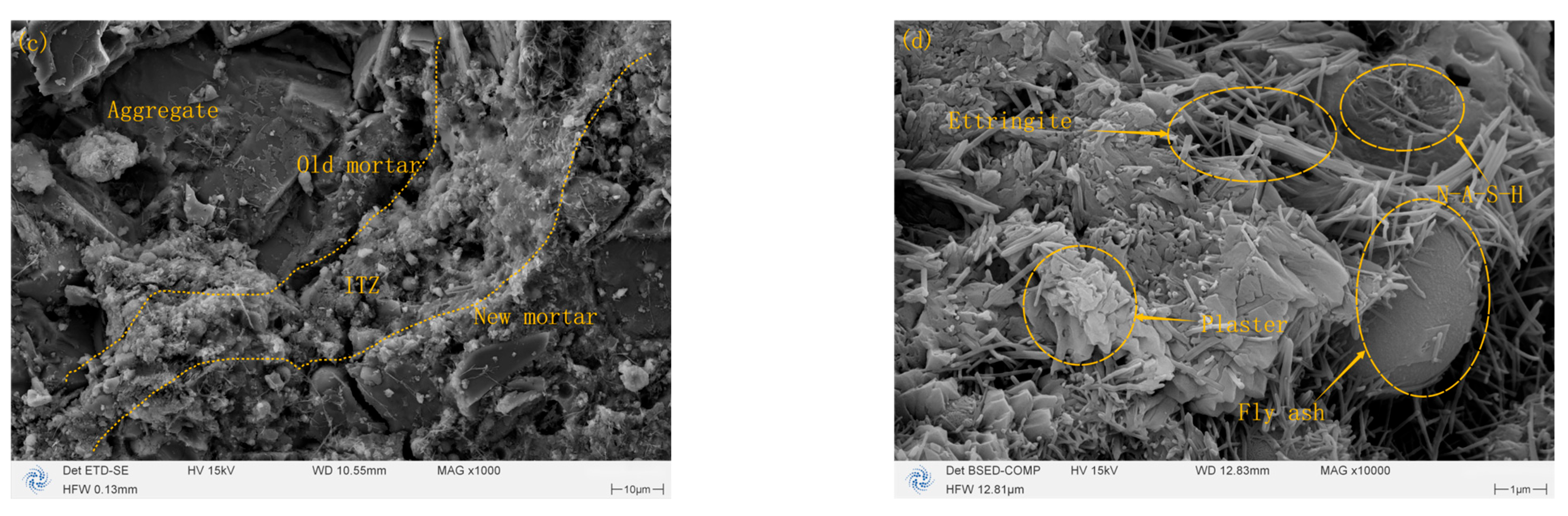
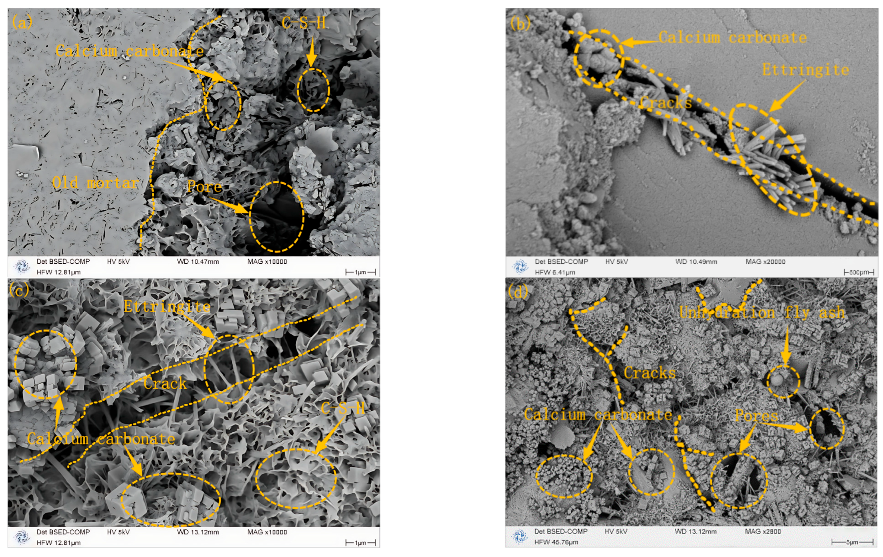
3.2. Comparative SEM Analysis of Microstructural Evolution Pre- and Post-Carbonization
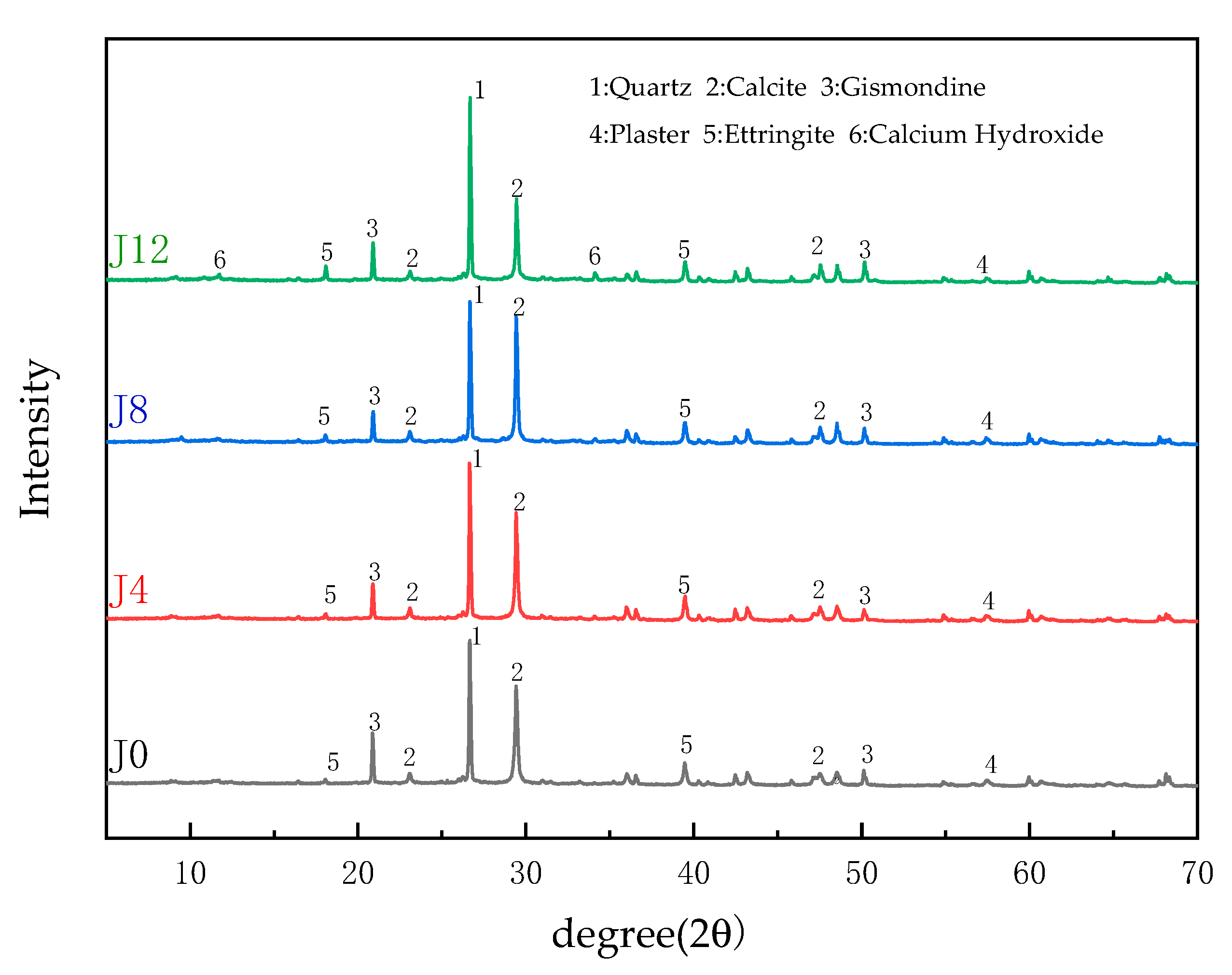
3.3. XRD Analysis of JFRAC
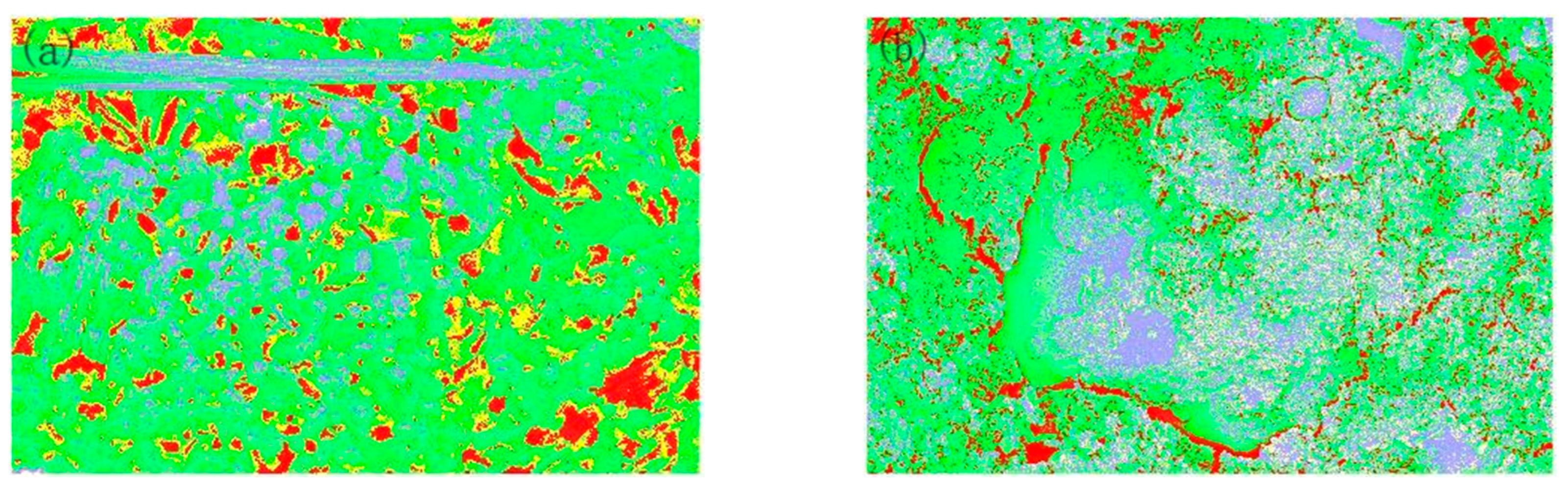
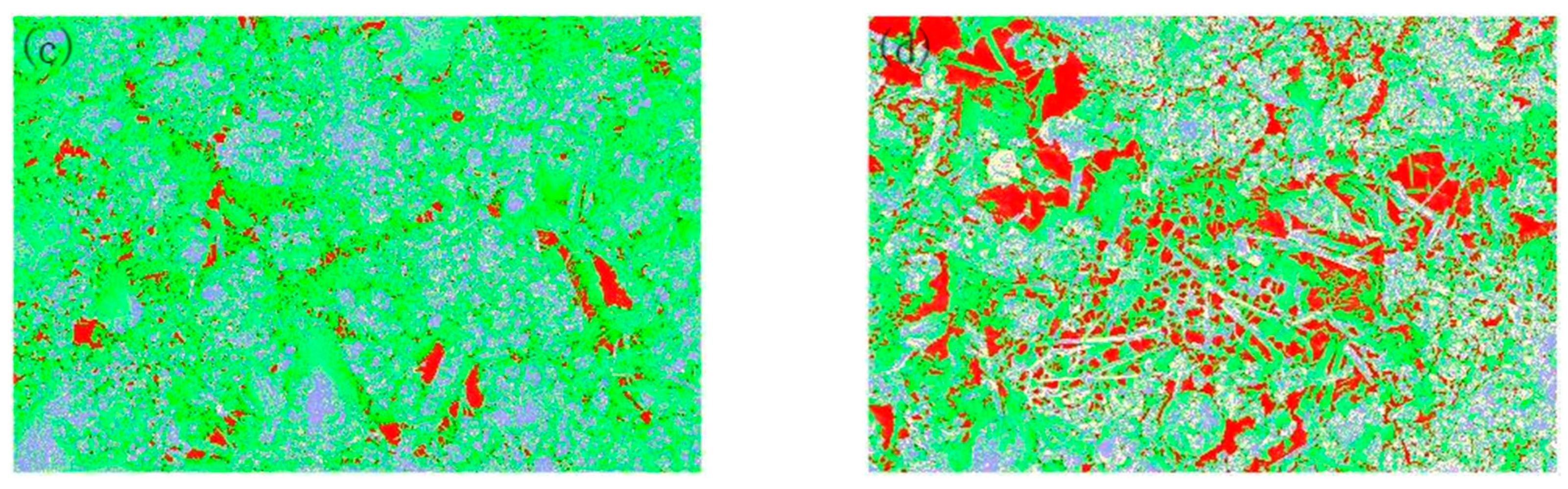
3.4. Effect of Carbonization on the Physical Phase Distribution of Pores
3.5. Fractal Analysis of Pore Structure Evolution in Concrete During Carbonation
3.6. Embodied Carbon Analysis
4. Conclusions
- (1)
- Optimal Alkali Dosage Enhances Carbonation Resistance and Microstructural Integrity: The incorporation of 8% CaO as an alkali activator significantly improves the carbonation resistance of fly ash recycled aggregate concrete (FRAC), achieving a 35% reduction in carbonation depth and a 10.76% increase in compressive strength compared to the control group. This optimal dosage promotes the formation of dense C–S–H/AFt networks, reduces porosity to 22.87%, and optimizes pore fractal complexity (FD > 1.9), effectively suppressing CO2 diffusion. However, excessive alkali activation (12% CaO) induces microcracks and pore interconnectivity, leading to a 7.6% strength reduction and accelerated carbonation.
- (2)
- Fractal–Pore Relationships Reveal Durability Mechanisms: Fractal dimension (FD) analysis establishes a quantitative link between pore complexity and macro-performance. A threshold of FD > 1.9 correlates with low pore connectivity and high durability, validating its role as a critical indicator for carbonation resistance. However, FD sensitivity to image resolution and binarization methods necessitates standardized protocols for future studies.
- (3)
- Environmental and Practical Implications: Despite the embodied carbon of CaO (9.84 kg CO2/m3), its synergy with fly ash (≈120 kg CO2/m3 reduction) and extended service life (15–20 years) ensure a net carbon benefit. This highlights the potential of alkali-activated FRAC in sustainable construction.
5. Study Limitations and Future Directions
5.1. Limitations
- (1)
- The current scope focuses on compressive strength and carbonation resistance. Other durability metrics (e.g., chloride ingress, sulfate attack) remain unexplored.
- (2)
- Thermogravimetric analysis (TGA) was not performed to quantify carbonation products.
- (3)
- The volumetric strain induced by CaO expansion was not directly measured.
5.2. Future Directions
- (1)
- Multidisciplinary Modeling: integrate DeepLabv3+ and EfficientNet-B7 for automated microstructural analysis, enabling the pixel-level quantification of pores, cracks, and ettringite morphology.
- (2)
- Extended Testing: evaluate carbonation behavior beyond 28 days to capture long-term degradation patterns.
- (3)
- Durability Expansion: validate the 8% threshold against chloride penetration, freeze–thaw cycles, and acid exposure.
Author Contributions
Funding
Data Availability Statement
Conflicts of Interest
References
- IEA. Cement Technology Roadmap: Carbon Emissions Reductions up to 2050; OECD Publishing: Paris, France, 2018. [Google Scholar]
- National Development and Reform Commission; Ministry of Housing and Urban-Rural Development. White Paper on Construction Waste Recycling in China 2025; China Architecture & Building Press: Beijing, China, 2025.
- Yu, P.; Li, T.; Gao, S.Q. Study on the effect of recycled fine powder on theproperties of cement mortar and concrete. Desalination Water Treat. 2024, 319, 100481. [Google Scholar] [CrossRef]
- Chen, X.H.; Lao, G.W.; Zheng, S.F.; Ling, F.; Xu, R.T.; Chen, Z.P. Effect of Fly Ash Content on Workability of Fully Recycled Coarse Aggregate Self- Compacting Concrete. Bull. Chin. Ceram. Soc. 2025, 44, 531–539. [Google Scholar] [CrossRef]
- Xie, J.H.; Zhao, J.B.; Wang, J.J.; Fang, C.; Yuan, B.; Wu, Y.H. Impact behaviour of fly ash and slag-based geopolymeric concrete: The effects of recycled aggregate content, water-binder ratio and curing age. Constr. Build. Mater. 2022, 331, 127359. [Google Scholar] [CrossRef]
- Jian, W.; Ma, Y. A semi-empirical model for predicting carbonation depth of RAC under two-dimensional conditions. Rev. Adv. Mater. Sci. 2023, 62, 20230115. [Google Scholar] [CrossRef]
- Jean, B.; Liu, H.; Zhu, X.D.; Wang, X.J.; Yan, X.C.; Ma, T.Y. Enhancing the Mechanical and Durability Properties of Fully Recycled Aggregate Concrete Using Carbonated Recycled Fine Aggregates. Materials 2024, 17, 1715. [Google Scholar] [CrossRef]
- Govardhan, C.; Gayathri, V. Experimental Investigation on Ternary Blended Recycled Aggregate Concrete Using Glass Fibers. Buildings 2023, 13, 1961. [Google Scholar] [CrossRef]
- Reddy, M.V.N.S.S.; Kumar, K.M.; Prathyusha, B.; Angel, Y.A.; Akhil, B.; Bhanu, N.; Reddy, S.A. Experimental Study on Potential Use of Recycled Aggregates in Concrete. Int. J. Innov. Res. Comput. Sci. Technol. 2023, 11, 78–81. [Google Scholar] [CrossRef]
- Sun, H.; Ma, Z.B.; Lu, G.J.; Liu, J.Y.; Miu, H.Q. Review on geopolymer preparation by alkali activation of coal fly ash. Clean Coal Technol. 2023, 29, 140–153. [Google Scholar] [CrossRef]
- Ding, Y.H.; Lv, X.W.; Yang, X.L.; Zhang, M.X.; Zou, C.L. Effect of pre-impregnated carbonized aggregate on carbonization resistance of fully recycled concrete. Ceram.-Silikáty 2023, 67, 207–216. [Google Scholar] [CrossRef]
- Lu, W.H. Effect of Large Amount of Mineral Blending Compound on Carbonization Resistance of Concrete. Master’s Thesis, Yanshan University, Qinhuangdao, China, 2022. [Google Scholar] [CrossRef]
- Li, X.G.; Wang, P.Q.; Zhang, Y.; Guo, Z.Z.; Cao, Y.J. Study on Capillary Negative Pressure and Interfacial Transition Zone of Regenerated Aggregate Concrete. J. Build. Mater. 2022, 25, 572–576. [Google Scholar]
- Song, Y.F.; Wang, J.Z.; Huang, Y.J.; Wang, J.W.; Weng, Y.T.; Ma, R.; Pang, K.S.H.P.; Ruan, S.Q. Effects of varying grades/pretreatments of recycled aggregates on the development of pore structures and ITZs within reactive magnesia cement (RMC) concrete. Cem. Concr. Res. 2025, 190, 107782. [Google Scholar] [CrossRef]
- Xu, L.; Wang, J.; Huang, R.; Li, B.; Ran, B.; Hu, X.C. Investigations on micro-mechanical properties of the ITZs between recycled aggregates and recycled cement paste. Constr. Build. Mater. 2024, 450, 138640. [Google Scholar] [CrossRef]
- Chen, X.Y.; Zhou, Q.; Chen, Z.Y.; Tu, Y.T.; Chen, X.Y.; Zhou, Q.; Chen, Z.Y.; Tu, Y.T. Effect of Nano-SiO2 on the Interface Transition Zone Between Oldand New Mortar of Recycled Concrete. Mater. Rep. 2022, 36, 191–195. [Google Scholar]
- Cheng, Z.Y.; Chen, T.F.; Tu, Y.P. Effect of Nano CaCO3 on Properties andMicrostructure of Fly Ash Recycled Aggregate Concrete. J. Build. Mater. 2023, 26, 228–235. [Google Scholar]
- Alsarhan, H.; Al-Fakih, A. Performance and sustainability of industrial by-products-based alkali-activated concrete: A review. Multiscale Multidiscip. Model. Exp. Des. 2025, 8, 215. [Google Scholar] [CrossRef]
- Liu, Z.T. Research on Preparation Technology and Performance of Alkali-Activated Recycled Concrete. Master’s Thesis, Qingdao University of Technology, Qingdao, China, 2021. [Google Scholar] [CrossRef]
- Jiang, M.S.; Li, F.; Zhou, L.A.; Ning, J.R.; Zhang, Z. Effects of Sodium Carbonate, Sodium Hydroxide and Water Glass Composite Activation on Properties of Geopolymer Cementitious Materials. Bull. Chin. Ceram. Soc. 2024, 43, 929–937. [Google Scholar] [CrossRef]
- Zhan, B.J.; Xuan, D.X.; Zeng, W.; Poon, C.S. Carbonation treatment of recycled concrete aggregate: Effect on transport properties and steel corrosion of recycled aggregate concrete. Cem. Concr. Compos. 2019, 104, 103360. [Google Scholar] [CrossRef]
- Zhang, D.S.; Wang, Y.F.; Ma, M.X.; Guo, X.J.; Zhao, S.Q.; Zhang, S.X.; Yang, Q.N. Effect of Equal Volume Replacement of Fine Aggregate with Fly Ash on Carbonation Resistance of Concrete. Materials 2022, 15, 1550. [Google Scholar] [CrossRef]
- Xiao, Q.H.; Guo, X.Y.; Qiu, J.S.; Wu, Z.; Shi, S.S. Influence of recycled aggregate content on carbonation performance of concrete. J. Xi’an Univ. Sci. Technol. 2023, 43, 972–979. [Google Scholar] [CrossRef]
- Zhang, W.; Duan, Z.H.; Liu, H.W.; Yao, Y.Z.; Zhang, Z.N.; Liu, C. Salt freezing-thawing damage evolution model based on the time-dependent hydration reaction incorporating rice husk ash and recycled coarse aggregate. Constr. Build. Mater. 2024, 440, 137179. [Google Scholar] [CrossRef]
- Li, Y.; Guan, M.S.; Wang, G.; Zhou, Z.X. Mechanical properties of fully recycled coarse aggregate concrete with manufactured sand. J. Shenzhen Univ. Sci. Eng. 2024, 41, 367–376. [Google Scholar] [CrossRef]
- Wu, J.C.; Wang, D.Z.; Ma, Z.P. Mechanical properties of UHPC enhanced by recycled fine aggregate and ultrafine fly ash. J. Funct. Mater. 2022, 53, 4193–4198. [Google Scholar]
- JTTE Editorial Office; Chen, J.; Dan, H.; Ding, Y.; Gao, Y.; Guo, M.; Guo, S.; Han, B.; Hong, B.; Hou, Y.; et al. New innovations in pavement materials and engineering: A review on pavement engineering research 2021. J. Traffic Transp. Eng. 2021, 8, 815–999. [Google Scholar]
- Zhao, Z.P. Formation of Ettringite and Its Effect on Shrinkage Properties of Alkali Slag Cement Mortar. Master’s Thesis, Chongqing University, Chongqing, China, 2021. [Google Scholar] [CrossRef]
- Ren, Q.W.; Yin, Y.J.; Shen, L. Fractal study of random distribution of concrete aggregates and its effect on damage characteristics. J. Hydraul. Eng. 2020, 51, 1267–1277+1288. [Google Scholar] [CrossRef]
- Gong, S.W.; Wang, T.; Hasan, M.M.; Mei, X.F.; Tan, Z.Y.; Su, T.; Cao, F.B. Effect of polypropylene fiber and nano-silica on the compressive strength and frost resistance of recycled brick aggregate concrete. Nanotechnol. Rev. 2023, 12, 20230174. [Google Scholar] [CrossRef]
- Li, S.H.; Li, S.; Du, G.; Gu, M. Experimental study on improvement of organic soil with cement and fly-ash. J. Eng. Geol. 2008, 16, 408–414. [Google Scholar]
- GB/T 50081-2019; Standard for Test Methods of Mechanical Properties of Ordinary Concrete. China Standards Press: Beijing, China, 2019.
- GB/T 50082-2024; Standard for Test Methods of Long-Term Performance and Durability of Ordinary Concrete. China Standards Press: Beijing, China, 2024.
- Wang, J.Y. Effect of Recycled Concrete Aggregate Carbonated Treaments on Permeablility and ITZs of Recycled Aggregate Concrete. Master’s Thesis, Hunan University, Hunan, China, 2017. [Google Scholar]
- Feng, G.R.; Ren, Y.F.; Zhang, X.Y.; Guo, Y.X.; Kang, L.X. The activating experimental research of fly ash for mining filling material in Tashan Mine. J. Chin. Coal Soc. 2011, 36, 732–737. [Google Scholar] [CrossRef]
- Schilling, P.J. The Structure of Cementitious Materials Produced by Alkali Activation of Calcium Aluminosilicate Glasses. Ph.D. Thesis, Louisiana State University, Baton Rouge, LA, USA, 1992. [Google Scholar]
- Provis, J.L. Alkali-activated materials. Cem. Concr. Res. 2018, 114, 40–48. [Google Scholar] [CrossRef]
- Huang, B.; Gong, Z.Y. Effect of alkali equivalent on compressive strengthand microstructure of alkali-excited slag cementitious materials. Hans J. Civ. Eng. 2023, 12, 1217–1222. [Google Scholar] [CrossRef]
- Zhang, S.Q.; Wu, B.; Ren, Y.T.; Wu, Z.P.; Li, Q.; Li, K.Q.; Zhang, M.G.; Yu, J.L.; Ni, W. The Preparation Process and Hydration Mechanism of Steel Slag-Based Ultra-Fine Tailing Cementitious Filler. Gels 2023, 9, 82. [Google Scholar] [CrossRef]
- Prasyanthi, D.; Saloma; Aminuddin, K.M. Sorptivity Analysis of Lightweight Concrete Based on Fly Ash and Bottom Ash. Int. J. Membr. Sci. Technol. 2023, 10, 2173–2186. [Google Scholar] [CrossRef]
- Ma, H.Z.; Li, Z.Q. Ettringite Formation in Concrete. Build. Sci. 2007, 11, 105–110+97. [Google Scholar]
- Zhang, X.; Lu, X.L.; Song, J.G.; Jia, J.; Yang, Q.C.; Du, P.; Cheng, X. Effect of NaOH on synthesis and transformation of ettringite under high temperature environment. J. Chin. Ceram. Soc. 2025, 53, 428–436. [Google Scholar] [CrossRef]
- Zhang, Y.K.; Raza, A.; Umar, M.; Chen, Y.; Yuan, C.F. Study on Frost Resistance and Interface Bonding Performance through the Integration of Recycled Brick Powder in Ultra-High-Performance Concrete for Structural Reinforcement. Materials 2023, 16, 6999. [Google Scholar] [CrossRef]
- Zhang, L.; Wu, G.Y.; Wu, Z.Q.; Xin, X.S.; Cai, J.X.; Cheng, X.W. Corrosion mechanisms of sulfoaluminate cement by highly sour gas. Pet. Drill. Technol. 2023, 45, 432–440+454. [Google Scholar] [CrossRef]
- Tian, X.; Zheng, Y.; Wang, C.; Cui, X. Preparation and Hydration Mechanism of Low Shrinkage Railway Sleeper Concrete Containing Hot Steaming Steel Slag. J. New Mater. Electrochem. Syst. 2020, 22, 112–118. [Google Scholar] [CrossRef]
- Xue, S.G.; Zhu, M.X.; Yang, X.W.; Guo, X.Y.; Jiang, F.Y.; Huang, S.W.; Zhu, F. Research progress of bauxite residue-activated cementitious materials and its engineering road application. Chin. J. Nonferrous Met. 2023, 33, 3421–3439. [Google Scholar]
- Liu, B.H.; Yi, D.H.; Fang, L. Study on bond behavior test and bond-slip constitutive model between straw ash concrete and reinforcement bar. Trans. Chin. Soc. Agric. Eng. 2018, 34, 239–246. [Google Scholar]
- Tu, L.Q. Researches on carbonation behavior and mechanism of shrinkage-compensated high performance concrete. Master’s Thesis, Wuhan University of Technology, Wuhan, China, 2011. [Google Scholar]
- Tang, S.; Wang, Y.; Geng, Z.; Xu, X.; Yu, W.; A, H.; Chen, J. Structure, Fractality, Mechanics and Durability of Calcium Silicate Hydrates. Fractal Fract. 2021, 5, 47. [Google Scholar] [CrossRef]
- Li, S.; Wang, Q.C.; Ma, L.; Yu, B.; Liu, Y. Study on Pore Volume Fractal Dimension for Cement Mortar with Different Air Contents. J. Highw. Transp. Technol. 2016, 33, 54–60. [Google Scholar]
- Liu, X.; Zhou, W.; Xie, G.; Peng, Y.; Liang, L.; Li, Y. Application basis and research progress of fractal theory in mineral processing. J. Chin. Coal Soc. 2023, 48, 3573–3588. [Google Scholar] [CrossRef]
- Hammond, G.P.; Jones, C.I. Embodied Energy and Carbon in Construction Materials. In Proceedings of the Institution of Civil Engineers-Energy, Bath, UK, 5 January 2008; Volume 161, pp. 87–98. [Google Scholar]
- Miller, S.A.; John, V.M.; Pacca, S.A.; Horvath, A. Carbon dioxide reduction potential in the global cement industry by 2050. Cem. Concr. Res. 2018, 114, 115–124. [Google Scholar] [CrossRef]


| Compressive Strength/MPa | Flexural Strength/MPa | Solidification Time/min | Stabilizing | ||||
|---|---|---|---|---|---|---|---|
| 3 d | 28 d | 3 d | 28 d | Initial Set | Final Set | ||
| Standardized value | ≥17.0 | ≥42.5 | ≥4 | ≥6.5 | ≥45 | ≤600 | Conformity |
| Measured value | 17.6 | 45.5 | 5.1 | 7.8 | 1545 | 371 | Conformity |
| Chemical Composition | SO3 | CaO | SiO2 | Al2O3 | Fe2O3 | MgO |
|---|---|---|---|---|---|---|
| Quantity contained (%) | 0.8 | 5.6 | 43 | 23 | 2.5 | 0.95 |
| Group | Cement (kg/m3) | Recycled Aggregate (kg/m3) | Coarse Aggregate (kg/m3) | Fine Aggregate (kg/m3) | Water (kg/m3) | Fly Ash (kg/m3) | CaO (kg/m3) |
|---|---|---|---|---|---|---|---|
| J0 | 287 | 338.33 | 789.42 | 607.25 | 221 | 123 | 0 |
| J4 | 287 | 338.33 | 789.42 | 607.25 | 221 | 123 | 4.92 |
| J8 | 287 | 338.33 | 789.42 | 607.25 | 221 | 123 | 9.84 |
| J12 | 287 | 338.33 | 789.42 | 607.25 | 221 | 123 | 14.76 |
| Pre-Carbonation | Post-Carbonization | |||
|---|---|---|---|---|
| Fractal Dimension Estimation | R2 | Fractal Dimension Estimation | R2 | |
| J0 | y = 0.16961 − 1.8912x | 0.998 | y = 0.11657 − 1.9296x | 0.999 |
| J4 | y = 0.14308 − 1.9041x | 0.999 | y = 0.11349 − 1.9306x | 0.999 |
| J8 | y = 0.14077 − 1.9147x | 0.998 | y = 0.09003 − 1.9474x | 0.999 |
| J12 | y = 0.16993 − 1.8915x | 0.998 | y = 0.12384 − 1.9257x | 0.998 |
Disclaimer/Publisher’s Note: The statements, opinions and data contained in all publications are solely those of the individual author(s) and contributor(s) and not of MDPI and/or the editor(s). MDPI and/or the editor(s) disclaim responsibility for any injury to people or property resulting from any ideas, methods, instructions or products referred to in the content. |
© 2025 by the authors. Licensee MDPI, Basel, Switzerland. This article is an open access article distributed under the terms and conditions of the Creative Commons Attribution (CC BY) license (https://creativecommons.org/licenses/by/4.0/).
Share and Cite
Huang, Y.; Gong, A.; Jin, Z.; Peng, Y.; Shao, S.; Yong, K. Synergistic Effects of Alkali Activator Dosage on Carbonation Resistance and Microstructural Evolution of Recycled Concrete: Insights from Fractal Analysis and Optimal Threshold Identification. Buildings 2025, 15, 1742. https://doi.org/10.3390/buildings15101742
Huang Y, Gong A, Jin Z, Peng Y, Shao S, Yong K. Synergistic Effects of Alkali Activator Dosage on Carbonation Resistance and Microstructural Evolution of Recycled Concrete: Insights from Fractal Analysis and Optimal Threshold Identification. Buildings. 2025; 15(10):1742. https://doi.org/10.3390/buildings15101742
Chicago/Turabian StyleHuang, Yier, Aimin Gong, Zhuo Jin, Yulin Peng, Shanqing Shao, and Kang Yong. 2025. "Synergistic Effects of Alkali Activator Dosage on Carbonation Resistance and Microstructural Evolution of Recycled Concrete: Insights from Fractal Analysis and Optimal Threshold Identification" Buildings 15, no. 10: 1742. https://doi.org/10.3390/buildings15101742
APA StyleHuang, Y., Gong, A., Jin, Z., Peng, Y., Shao, S., & Yong, K. (2025). Synergistic Effects of Alkali Activator Dosage on Carbonation Resistance and Microstructural Evolution of Recycled Concrete: Insights from Fractal Analysis and Optimal Threshold Identification. Buildings, 15(10), 1742. https://doi.org/10.3390/buildings15101742