1. Introduction
The building of resilient civil infrastructure requires high-performance materials. Concrete-like composites are widely used in engineering and material science worldwide. Over the past decades, the analysis of concrete-like composites has remained an active area of research. The mechanical and physical properties of concrete-like materials are closely related to their mesoscale structures, such as the particle shape, grading, volume fraction, and interface transition zone (ITZ) [
1]. The design of high-strength composites depends on understanding and optimizing the mesostructure of these materials. Numerical methods provide an effective and efficient alternative to laboratory investigations for analyzing concrete-like composite materials [
2,
3].
In numerical analysis, the mesostructure is a prerequisite for studying the performance of concrete-like composites. The generation of mesoscale structures can generally be classified into two categories. The first category involves digital image processing methods combined with images obtained through techniques such as X-ray Computer Tomography (XCT), cameras, microscopes, and scanners [
2,
3,
4,
5]. For example, Nitka et al. proposed an X-ray CT image-based discrete element method (DEM) to investigate fractures in concrete beams [
6]. Yang et al. analyzed fracture evolution using digital volume correlation (DVC) mapping and micro XCT tests [
7]. Meng et al. developed an open-source software package for heterogeneous material modeling based on digital image processing [
8]. While this method can provide an accurate mesostructure of concrete, it is limited by the resolution of the imaging equipment and the significant effort required to obtain different types of concrete-like mesostructures.
The second category encompasses random mesostructure generation methods. Over the past 30 years, numerous studies on random mesostructure generation for concrete-like materials have been proposed [
9,
10,
11,
12,
13,
14]. The “take-and-place (TAP)” algorithm, which generates aggregates first and then locates the particles within a specific domain, is commonly used by researchers [
9,
10,
15,
16]. A modified solution called the “occupation and removal method (ORM)” improves the efficiency of generating mesostructure models [
17,
18]. However, this method relies on collision detection algorithms and struggles to achieve high volume fractions. Another method, the “divide-and-fill (DAF)” approach, divides the domain into sub-areas such as triangles or polygons and fills them with particles [
14,
19,
20,
21]. While this method can achieve very high volume fractions, generating aggregate structures with specified particle distributions is highly complex. Additionally, methods based on computational dynamic simulations, such as the explicit finite element method (FEM) [
22], molecular dynamics (MD) [
23], and physics engines [
24], have been developed. Compared to the TAP and DAF methods, these methods can generate random aggregate structures with high volume fractions and complex particle distributions. However, obtaining random aggregate structures with high volume fractions and complex particle shapes that are suitable for finite element mesh generation remains a challenge.
Current random mesoscale generation techniques have several limitations. They often fail to accurately represent the complex geometries and distributions of particles found in real concrete-like materials. Achieving high volume fractions while maintaining computational efficiency is a significant challenge. Many methods also inadequately account for the ITZ, which is critical for understanding the mechanical behavior of concrete-like composites.
To address these limitations, this work proposes a novel DEM-enhanced external force-free method for generating multi-phase mesoscale models for concrete-like composites with arbitrary aggregate shapes. By employing Minkowski sum theory, the minimum gap between adjacent particles and the thickness of the ITZ can be flexibly controlled. This method also leverages the periodic boundary condition of the DEM, making it easier to obtain periodic boundary conditions in the generated models. The proposed method overcomes the limitations of previous techniques by providing a more accurate and flexible representation of the mesostructure of concrete-like composites. It allows for the generation of complex particle distributions with high volume fractions while maintaining computational efficiency. Furthermore, the ability to control the minimum gap and ITZ thickness enables a more detailed investigation of the mechanical properties of concrete-like materials. This advancement contributes to a better understanding of the relationship between the mesostructure and macroscopic properties of concrete-like composites, which is essential for the design and optimization of high-performance concrete materials.
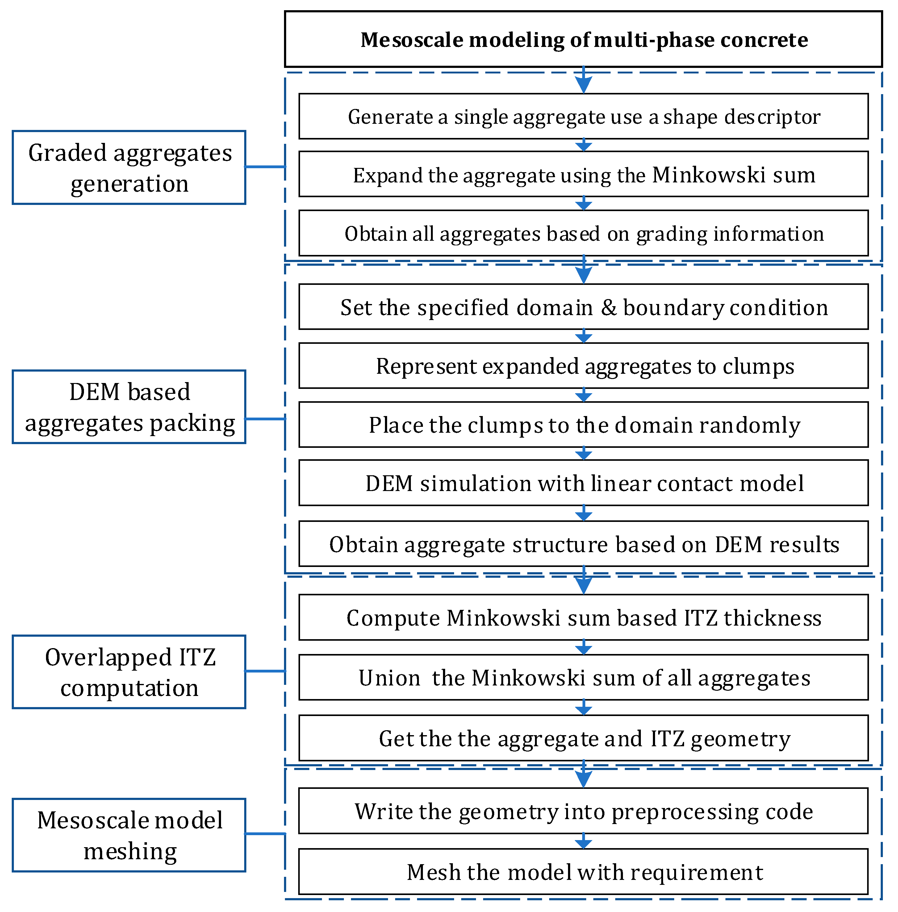
2. Methodology
Mesoscale modeling for multi-phase concrete-like composites has four procedures in this study. The first is the generation of aggregates based on the grading information. Secondly, the generated aggregates will be packed into a specific domain, ensuring that the particles cannot collide with each other. Though an effective algorithm like the separation axis theorem (SAT) or the Gilbert–Johnson–Keerthi (GJK) method is used, this procedure is still time-consuming. It is performed efficiently by a modification of the DEM simulation in this work. Considering that the ITZ is an important part of concrete, an overlapped ITZ geometry computation algorithm is proposed. Finally, a mesoscale model meshing procedure is employed to obtain the periodic FEM grid. The whole process is shown in
Figure 1.
Compared with the previous studies, this work presents multi-phase concrete-like composites generation with aggregates, an ITZ, and a matrix with an arbitrary shape and a high fraction. It will be helpful to understand the complex mechanical behavior of concrete material.
2.1. Generation of Graded Aggregates
2.1.1. Generation of a Single Aggregate
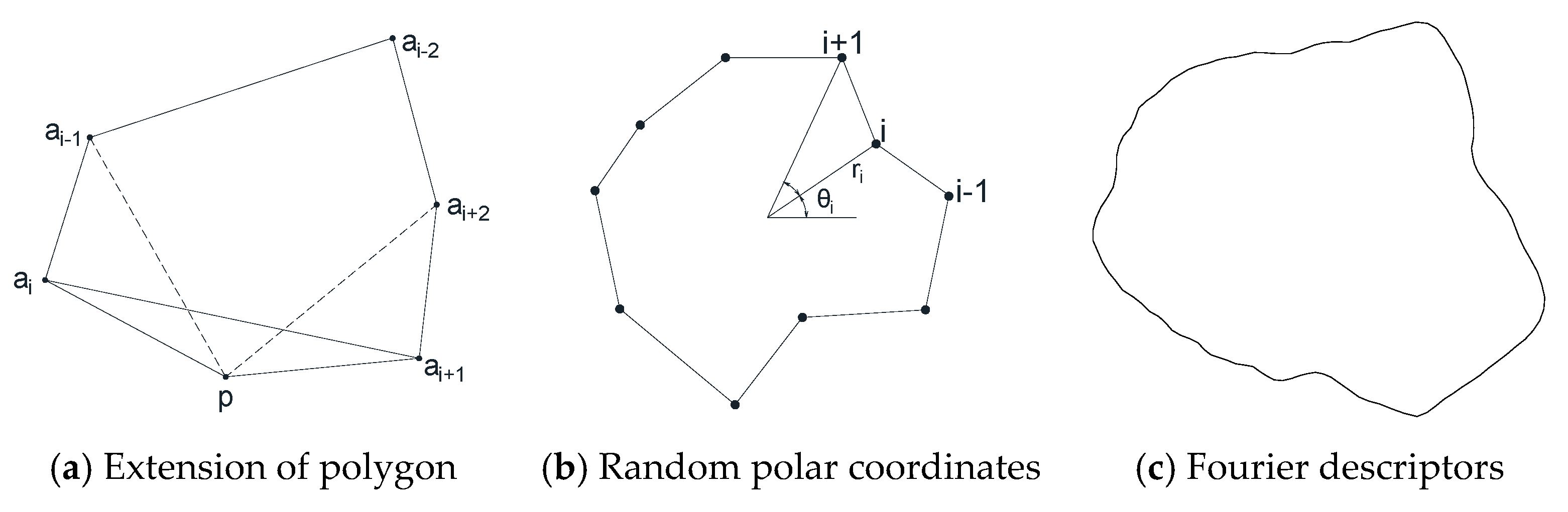
The generation of aggregates is the first step in mesoscale modeling of concrete-like composites. Previous studies have proposed several methods. In this study, we utilize a method based on the Minkowski sum theory to generate aggregates with arbitrary shapes. One method uses a random extension of the polygon aggregate algorithm [
25,
26] (
Figure 2a). In this method, only convex shapes are generated. Another approach employs a series of random radii and angles in polar coordinates to generate an aggregate [
10,
27], as shown in
Figure 2b. Compared with the first method, this approach allows for both convex and concave aggregates. The third method is based on Fourier descriptors to generate the shape of the aggregates [
20,
28,
29] (
Figure 2c) and excels in describing complex shapes. While the first two methods are relatively easy to implement, they are limited to describing simple shapes. In contrast, the last method is more advantageous for capturing complex geometries. By leveraging the Minkowski sum theory, our work supports the generation of aggregates with arbitrary shapes, offering a more versatile and accurate representation of concrete-like composites.
In the mesoscale modeling of a random aggregate structure, the aggregates are not allowed to connect to each other. A larger aggregate is generated using the Minkowski sum with a disk in this work. The Minkowski sum theory was named by the great German mathematician Hermann Minkowski and is widely used in computational graphics [
30,
31]. The Minkowski sum of point sets A and B is defined as:
The Minkowski sum is a mature theory, and there are many codes used to handle this problem, such as CGAL [
32] and OpenSCAD [
33]. However, the original Minkowski sum is only suitable for convex polygons. For two concave polygons, two sets of convex sub-polygons are computed using the convex decomposition. Afterward, the pairwise sums using the simple Minkowski sum procedure and the union operation can be used to obtain the final shape. As for the thickness offset of the aggregate, we can add the original particle with a small disk, as shown in
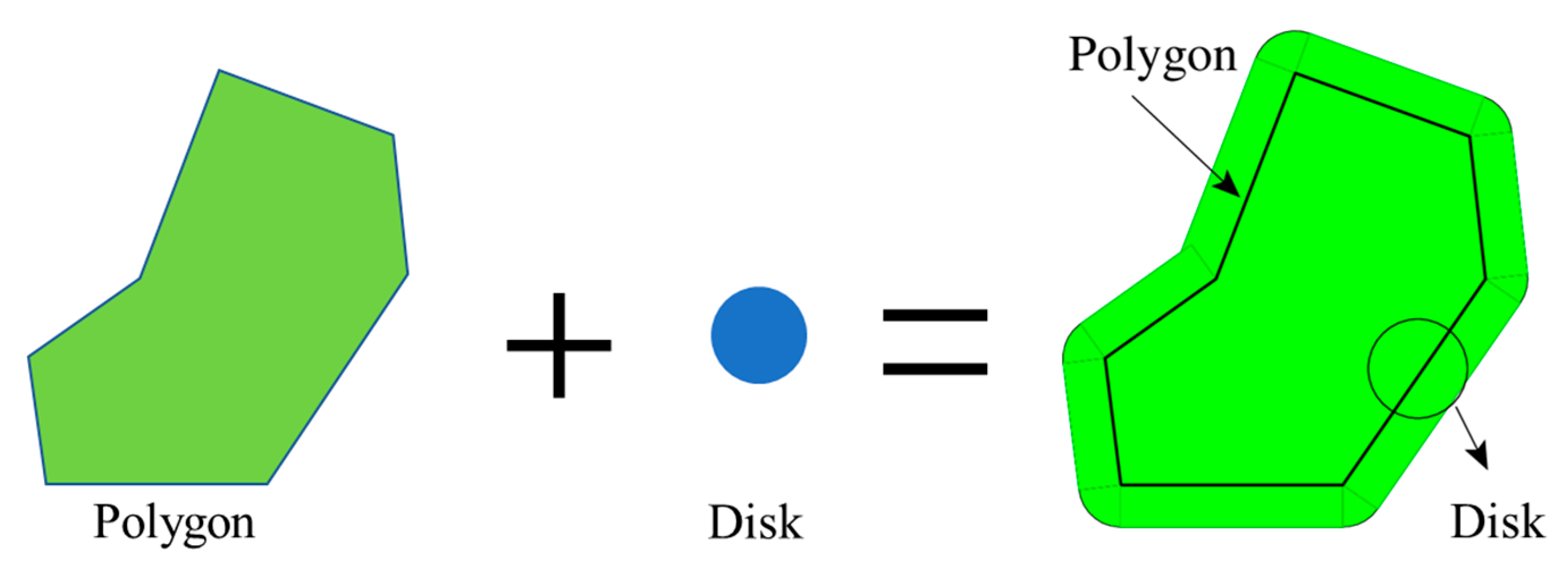
Figure 3. The minimum gap between adjacent aggregates can be precisely managed by adjusting the radius of the added disk.
Figure 3 graphically demonstrates the thickness offset technique using the Minkowski sum. Initially, the original concave polygon, symbolizing the aggregate, is displayed on the left. Centrally positioned is a small disk, appended to the original particle to establish a buffer zone; modifying the disk’s radius permits control over the offset thickness. Subsequently, the Minkowski sum procedure is executed on the original polygon and the disk. The outcome, illustrated on the right side of the figure, is a new shape that encapsulates both the original particle and the added disk, as shown in green. This effectively increases the thickness surrounding the particle. By altering the disk’s radius, we can exactly regulate the spacing between particles. This approach guarantees that the mesoscale model accurately mirrors the intended physical properties of the concrete-like composite, offering a visual interpretation of the Minkowski sum theory’s practical application in managing aggregate geometry within our model.
2.1.2. Size Grading of Aggregates
The grading curve, given by a series of cumulative percentages P(
d) and aggregate sizes (
d), is employed to describe the size distribution of the aggregate. In practice, concrete material is mostly designed using the Fuller curve, which represents a grading of aggregate particles resulting in the optimum density and strength of the concrete mixture [
11]. The Fuller curve for 3D cases can be described using a simple formula, as follows:
where
is the fraction of the aggregates.
For 2D mesoscale modeling of concrete, an equivalent transform from the 3D distributions to 2D distributions of aggregates is a crucial issue. To solve this problem, a solution was proposed by Walraven [
32]:
where
is the projected diameter of a round aggregate in a cross-sectional plane.
Employing the proposed grading curve method, a series of aggregates can be generated one by one. After all the original and offset aggregates are obtained, they will be placed in a specified domain using a DEM-based packing algorithm.
2.2. DEM-Based Aggregate Packing
2.2.1. Clump Generation of Aggregate
The DEM was first introduced to analyze rock mechanics problems and then applied to soils by Cundall and Strack [
33]. The DEM allows finite displacements and rotations of discrete bodies, including complete detachment, and recognizes new contacts automatically as the calculation progresses. Compared with the previous FEM-based packing method, the DEM is a particle-based approach with high efficiency in multibody simulation. The representation of the aggregate shape is very important in DEM simulation. Previous studies have proposed several solutions for this problem [
34,
35,
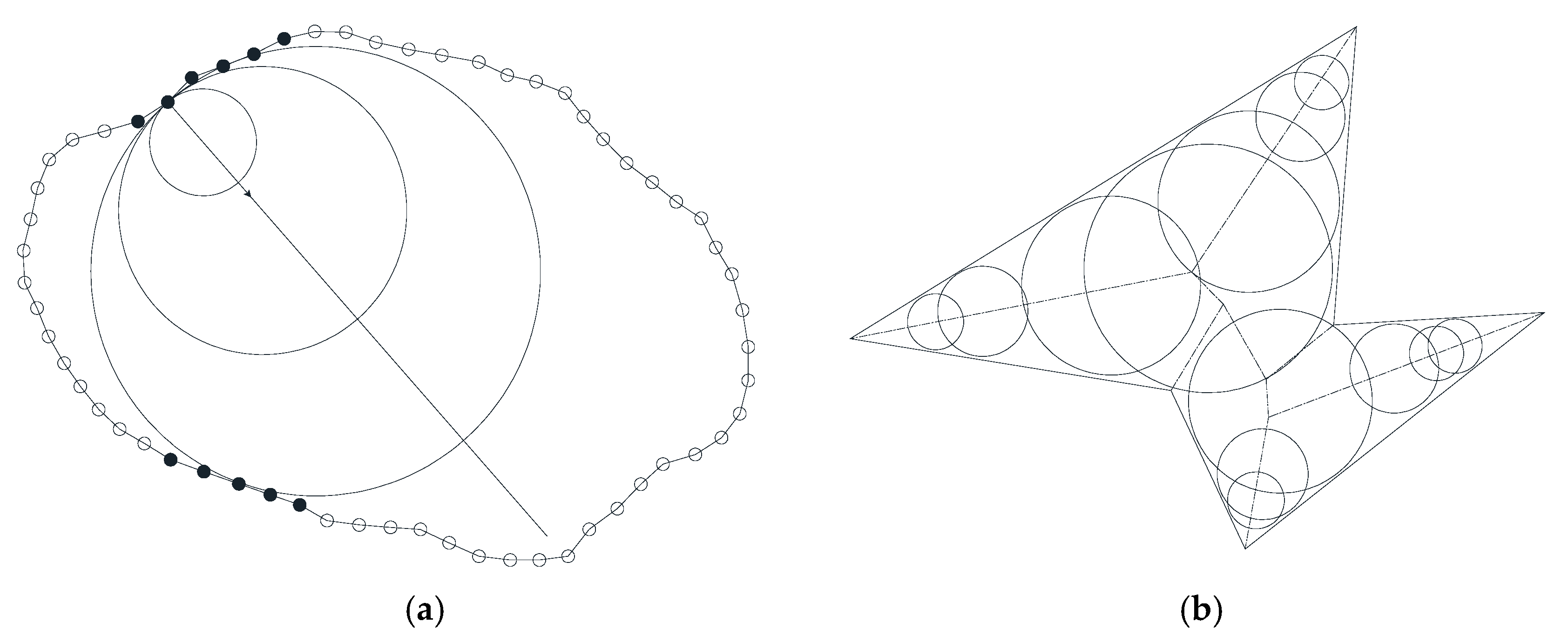
36]. In this work, the overlapping discrete element cluster (ODEC) generation algorithm shown in
Figure 4 is employed.
Figure 4a shows the expansion process of the disc, and the initial aggregate shape is constructed by gradually increasing the elements.
Figure 4b gives an example of cluster generation, showing how multiple aggregates are combined to form a cluster. During the generation process, each element is checked for overlap with the existing aggregate, ensuring that the minimum gap between the aggregates is controlled. In this way, the required aggregate shape and size can be accurately constructed.
To control the minimum gap between adjacent particles, the offset aggregates are used to generate ODECs. There are many open-source and commercial DEM codes, like Yade [
37] and EDEM, that can be employed. The commercial DEM code PFC is used, and the ODEC of each aggregate is called a clump in the simulation. The algorithm with its pseudo code is as follows (Algorithm 1):
| Algorithm 1 The algorithm of ODEC |
1: function generate_ODECs(radius, grid_size):
disk = create_disk(radius)
grid = divide_into_grid(disk, grid_size)
aggregates = []
for element in grid:
if not overlaps_with_existing_aggregates(element, aggregates):
add_element_to_aggregate(element, aggregates)
clump = combine_aggregates(aggregates)
return clump |
2.2.2. Overlapped Clumps Placement
In previous studies, the free-falling packing method under gravity loading was employed [
22,
38]. However, the movement under gravity loading leads to an inhomogeneous distribution, namely dense packing at the bottom and loose packing at the top. Furthermore, a large space is initialized and requires slightly more computational time.
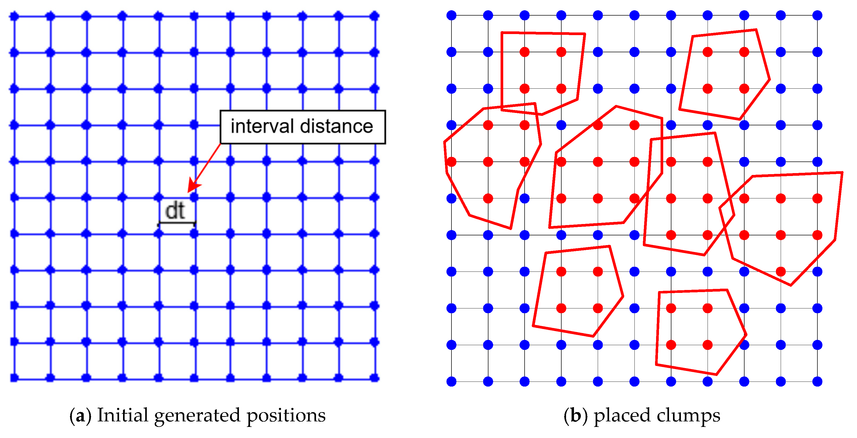
In this work, an external force-free method is presented. The clumps are placed in a constraint domain in an overlapped manner. If random placement is employed and a large coincidence of clumps exists, this may induce a numerical instability. To solve this problem, a modified clump placement is proposed, as shown in
Figure 5. The blue points indicate the positions where particles can be placed, and the red points denote the occupied positions. Before a particle is placed, all the possible positions are calculated with a specified interval distance denoted as
(
Figure 5a). When a clump is placed, the points in the aggregate will be removed, and the possible positions will be updated (
Figure 5b). In this way, the collision area between the new aggregate and the existing aggregate is reduced, improving the performance of the DEM simulation.
2.2.3. DEM Simulation of Aggregate Clumps
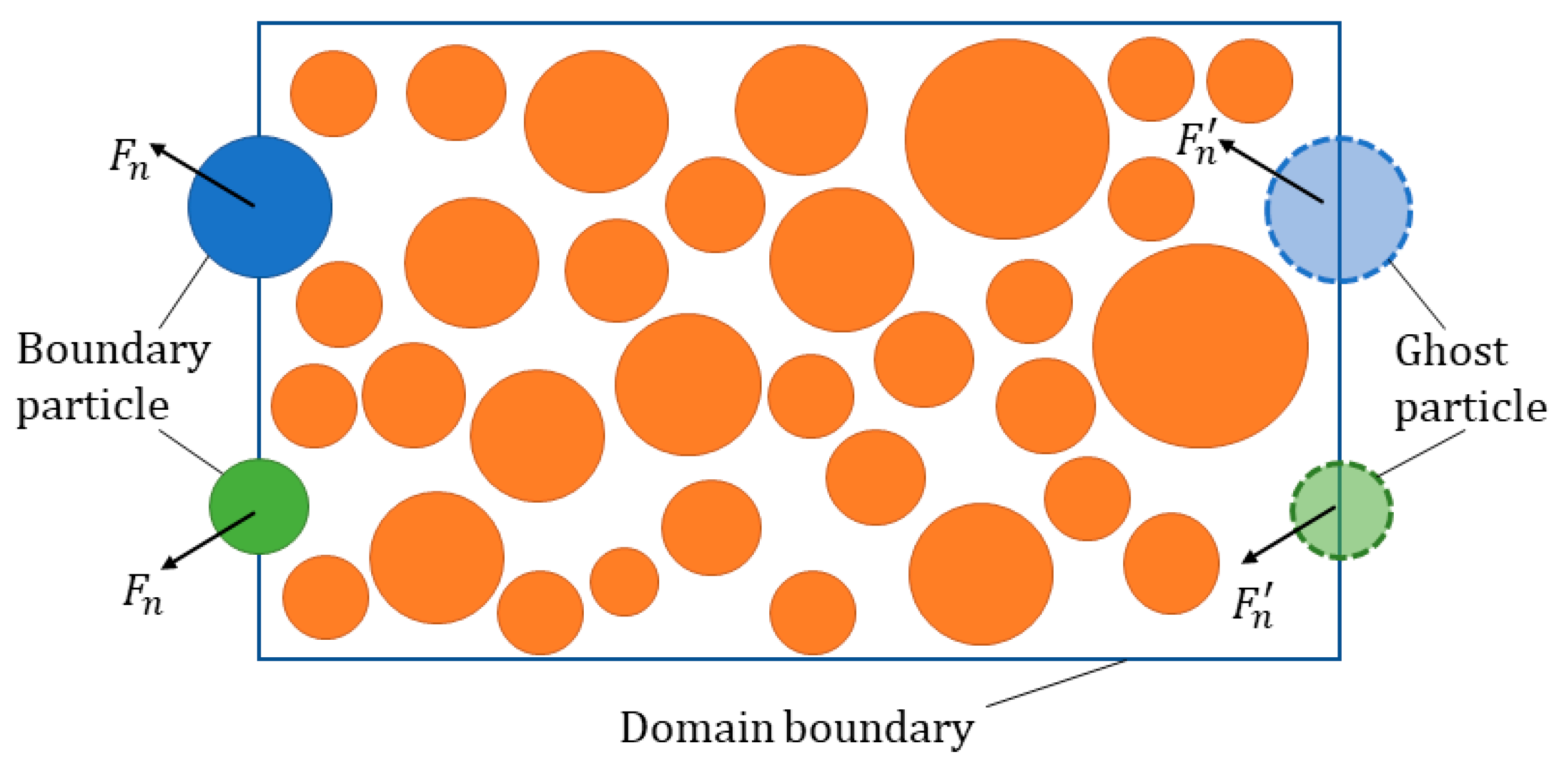
After the clumps of all the aggregates are generated, it is easy to pack them using DEM simulation. There are two kinds of border situations in mesoscale modeling based on whether the aggregates are allowed to be placed at the border. Correspondingly, two types of boundaries, called periodic and rigid, are employed in the simulation.
For the periodic modeling, the domain boundary should be the same as the sample size. In fact, there are three kinds of domain conditions: reflect, destroy, and periodic in the PFC code [
39]. The periodic condition applies periodic boundary conditions. When the clump centroid falls outside of the model domain, they are translated back to the opposite side of the model. To ensure that contacts are created as if the model was continuous, “ghost” balls and clumps are introduced (shown in
Figure 6). In the multiscale analysis, the periodic structure is preferred. An extra algorithm should have been employed in previous studies [
18,
27]. In this work, the periodic structure can be realized by just setting the periodic domain boundary.
For cases in which the aggregates cannot be located at the border, the rigid boundary can be realized using a wall in PFC. The domain size should be a little larger than the sample to make sure that the aggregate cannot reach the domain boundary. Otherwise, the size of the rigid wall may be slightly less than the sample. In this way, the clumps of the aggregates are constrained in the specified region.
As for the contact of clumps, a linear model with normal and tangential stiffness is used. It is a basic model in DEM, and the contact forces in the normal and shear directions are written as:
where
is the normal contact force,
is the normal secant contact stiffness,
is the total normal displacement,
is the unit normal vector,
is the shear stress increment,
is the shear stiffness, and
is the shear displacement increment.
The friction parameter affects the rotation of clumps and can be set to 0 in the simulation. Moreover, the rotation of clumps can be fixed if the aggregates are distributed in a certain direction. After all these parameters are properly set, the simulation can be performed easily.
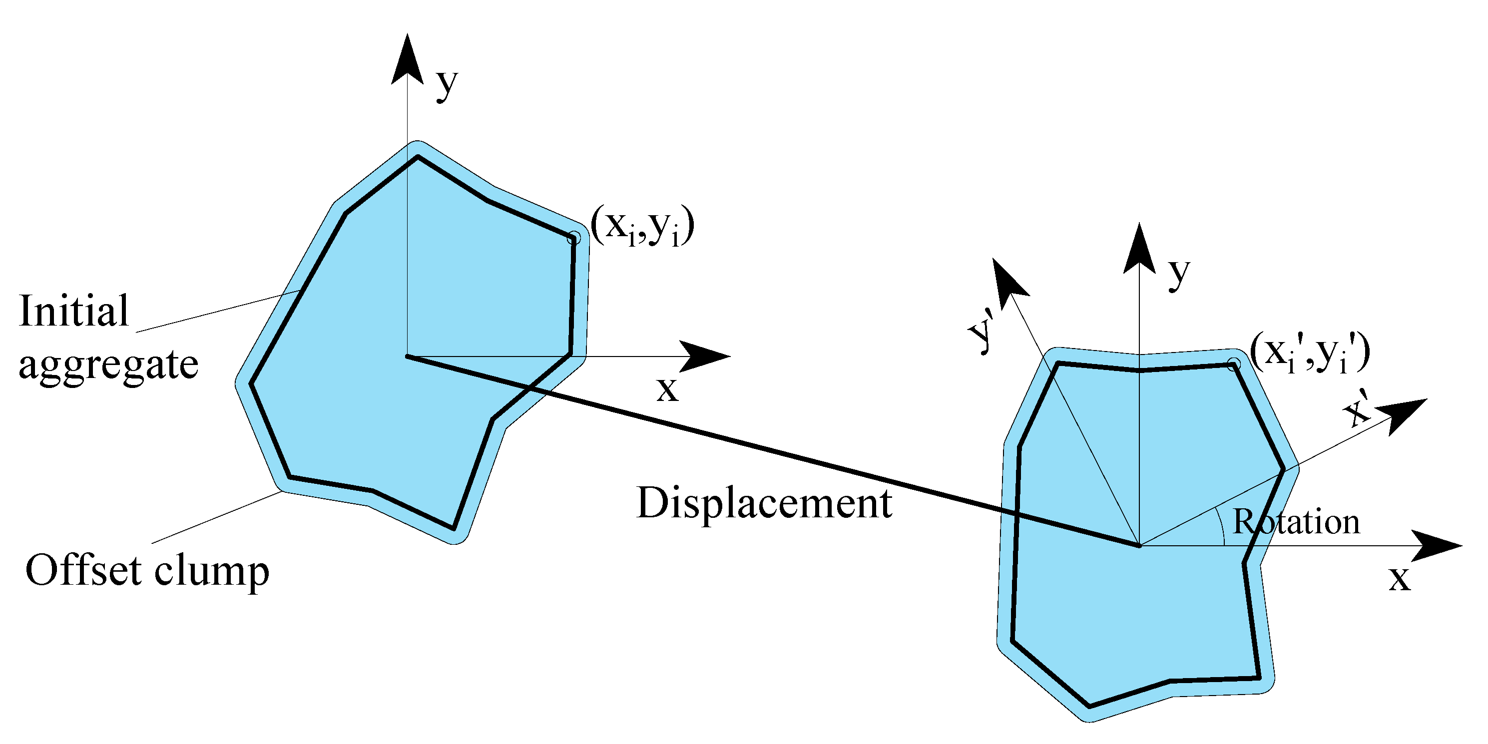
2.2.4. Computation of Aggregate Structure
The DEM simulation can only provide information on the clumps. To obtain a random structure, a process translating the clumps to aggregates is required. Firstly, the centroid of the clumps is recorded before DEM packing. Secondly, the displacement and rotation of each clump are obtained after the DEM simulation is finished. Finally, the geometry of the aggregate is computed based on the translation and rotation transformation (
Figure 7).
It should be noted that the information presented is for the offset aggregate, and the original aggregate is employed to obtain the random aggregate structure. If the vertex of the original aggregate is (
xi,
yi) and the center of the offset clump is (
xc,
yc), the final position
of the aggregate can be computed with displacement and rotation [
40].
where dx and dy are the components of displacement and
is the rotation angle.
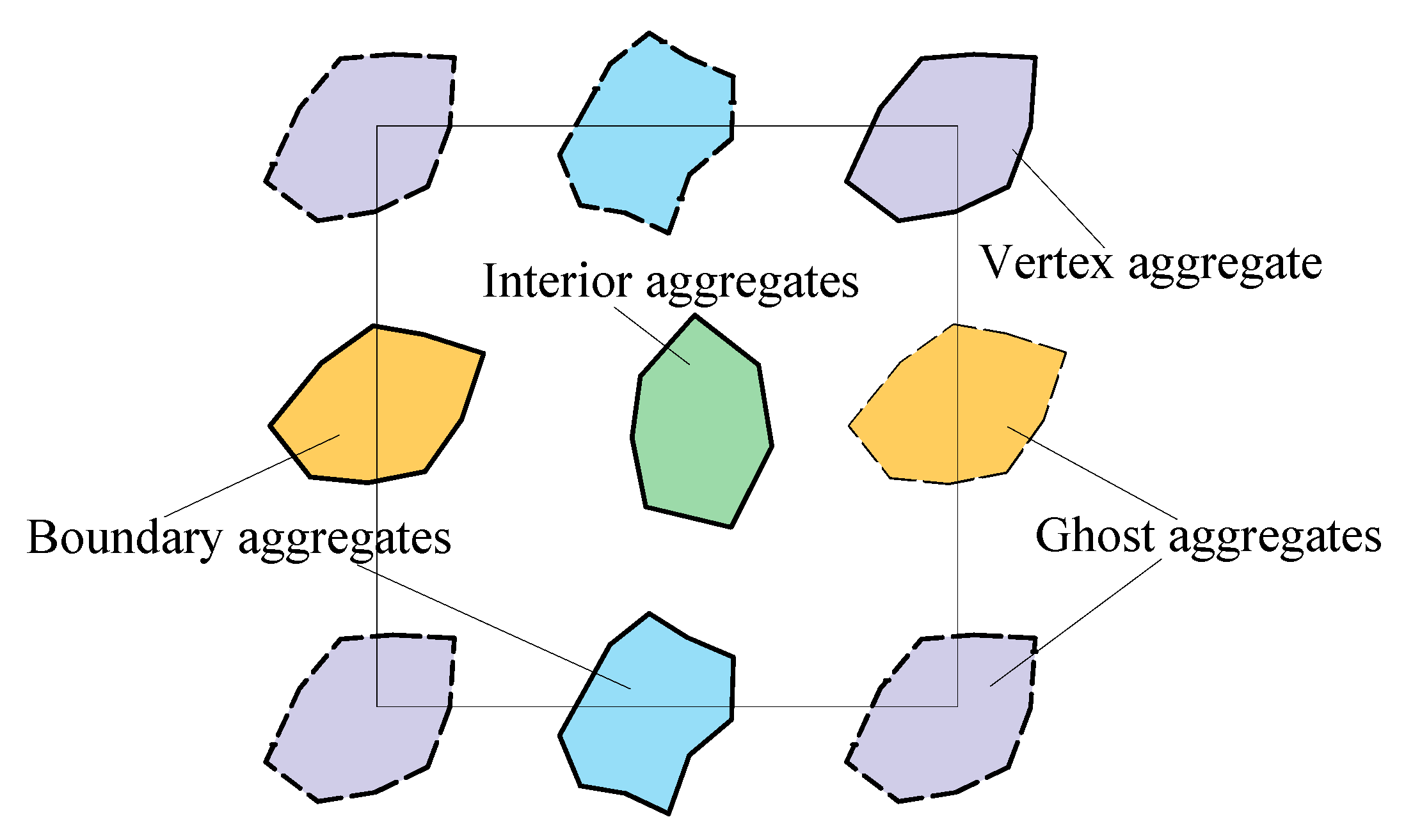
In the computation of the aggregate structure, the information of ghost clumps cannot be obtained using the PFC 9.0. Therefore, an extra code should be developed to calculate the ghost aggregate information, as shown in
Figure 8. This extra code plays a crucial role in the simulation process. Specifically, it helps to calculate the positions and properties of ghost aggregates, which are essential for applying periodic boundary conditions accurately. All the aggregates can be divided into three categories: the vertex aggregate, boundary aggregate, and interior aggregate. If the aggregate occupies the vertex of the domain, three ghost aggregates will be generated at the other three vertices. Furthermore, one ghost aggregate will be added if the clump is at the boundary line. No action is performed for the interior aggregates. By calculating the ghost aggregate information, the code ensures the accurate application of periodic boundary conditions, which is vital for the reliability of the simulation results.
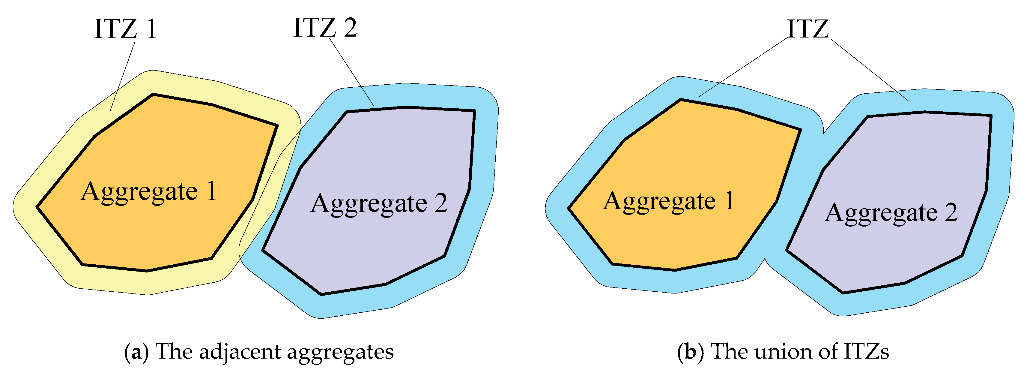
2.3. Overlapped ITZ Computation
The computation of the ITZ is another problem after the random aggregate structure is generated. One common method is to insert the cohesive element into the interface of the aggregate and mortar [
41,
42]. This method is very effective, but may have difficulty in simulating certain special problems like percolation. Another geometrically constructed ITZ using the Minkowski sum method is a good solution [
43,
44]. This operation is the same as that in
Section 2.1. If the thickness is large, there are overlapped ITZs. Therefore, an extra union operation, as shown in
Figure 9, is implemented.
2.4. Mesoscale Model Meshing
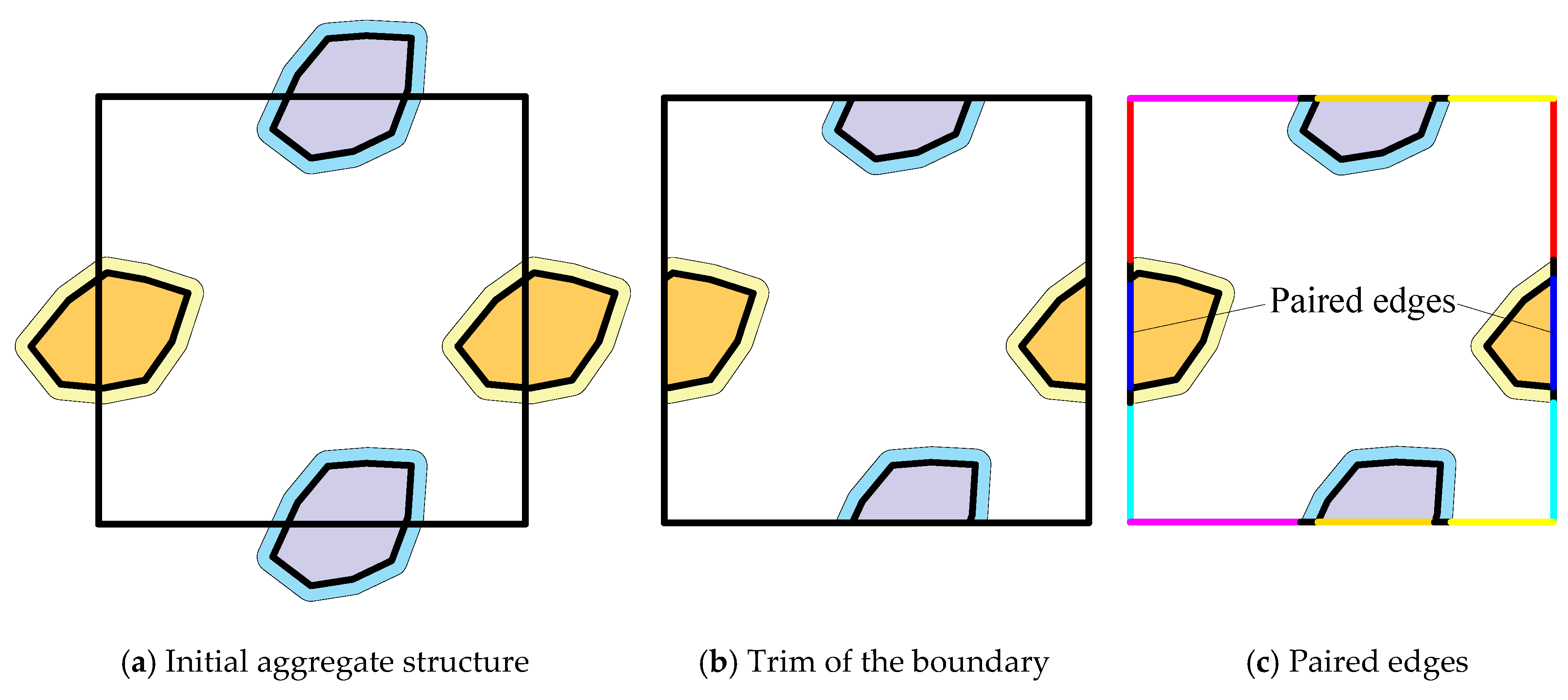
Mesoscale model meshing for the aggregate structure has two steps (
Figure 10). The first step is trimming the aggregates at the boundary of the domain and obtaining the periodic boundary structure. This process can be performed in CAD 2024. The second step is periodic meshing of the periodic structure. All the edges are computed and sorted into pairs, as shown in
Figure 10c. The paired edges are meshed with the same number of elements, and the other edges will be meshed by default. In this way, the periodic mesh, which is especially preferred in multiscale simulation, will be generated automatically.
3. Multi-Phase Concrete-like Composite Modeling
3.1. Modeling Process
Based on the proposed method, this section provides a detailed illustration of multi-phase concrete-like composite modeling. The aggregate size distribution reported by Wang et al. [
42] and shown in
Table 1 is employed. In actual engineering, concrete contains coarse and fine aggregates. The size of fine aggregates is petite, and only coarse aggregates are generated in mesoscale modeling. The cut-off size between coarse and fine aggregates is taken to be 1.18 mm.
Based on the grading information of aggregates, a multi-phase concrete-like composite model with an aggregate volume fraction of 60% is employed to show the performance of this method. According to the Standard for test and evaluation of concrete GB50107-2010 [
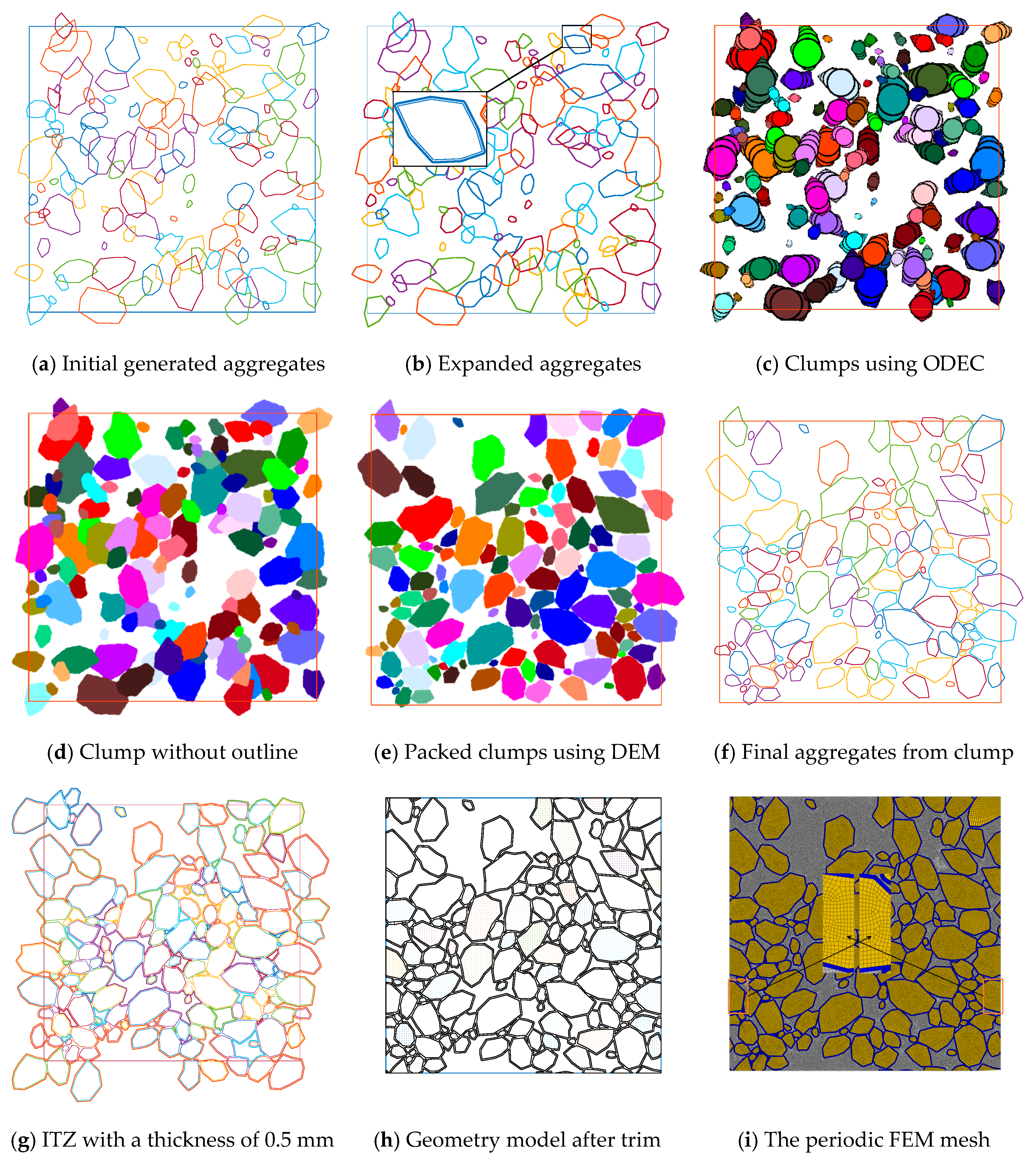
45], the size of the model is set as a square with dimensions of 100 mm × 100 mm. The aggregate is generated using a series of random radii and angles in polar coordinates. The initial generation of the aggregates is shown in
Figure 11a. A minimum gap distance mGap = 0.25 is realized by implementing the Minkowski sum operation with a disk of 0.25 mm. The geometry of the expanded aggregates is drawn with a bold line (
Figure 11b).
Afterward, the expanded aggregates are transformed into DEM clumps based on the ODEC algorithm, as shown in
Figure 11c. It can be seen that the aggregate can be represented accurately using a limited number of disks. In this simulation, there are 126 aggregates, and only 1898 disks are employed. Compared with FEM-based dynamic simulation, the DEM-based packing method has obvious advantages. By hiding the outline of the disks, a clear image of the clumps is given in
Figure 11d. The periodic boundary condition is employed to obtain a periodic structure. A simple linear contact model with a set of parameters in
Table 2 is used in the simulation. The physical time of this simulation is 5 s and the computation time for the whole process is 42.31 s using a desktop with AMD 3900X and 16G memory. The final packed clumps are presented in
Figure 11e.
Based on the displacement and rotation of the clump, the final position of the aggregates can be calculated easily using Equation (5). The aggregate information is drawn in
Figure 11f, and it is noted that the ghost aggregates are not generated. Then, the ghost aggregates are added, and an ITZ with a thickness of 0.5 mm is computed using the Minkowski sum algorithm. A union operation of the overlapped ITZs is implemented. The final aggregate and ITZ boundaries are presented in
Figure 11g. By trimming the domain using these boundary lines, the geometry of the mesoscale model is obtained, as shown in
Figure 11h in ABAQUS 2024. Afterward, a simple Python 3.12 script is developed to calculate the paired edges and assign the same seeds. In this way, the final FEM mesh with 76,129 nodes and 78,578 elements is finally obtained in
Figure 11i. The local enlarged image indicates that the mesh is periodic, applicable to multiscale simulation.
3.2. Validation
In order to evaluate the accuracy of the modeling method, we use ABAQUS for uniaxial compression and compare it with the experimental data of previous studies [
44] to verify the accuracy of the numerical model.
The material parameters of the model are shown in
Table 3, and the calculation results are shown in
Table 4. It can be seen from
Table 4 that the calculated results are in good agreement with the experimental results. In addition, the consistency between the numerical results and the experimental data shows the validity of the numerical model.
However, subtle differences can also be found. This is mainly due to the addition of the ITZ, which plays an important role in the apparent modulus of the composite because its elastic modulus is lower than that of the matrix [
46]. Therefore, the presence of the ITZ leads to a decrease in the apparent modulus of the composites.
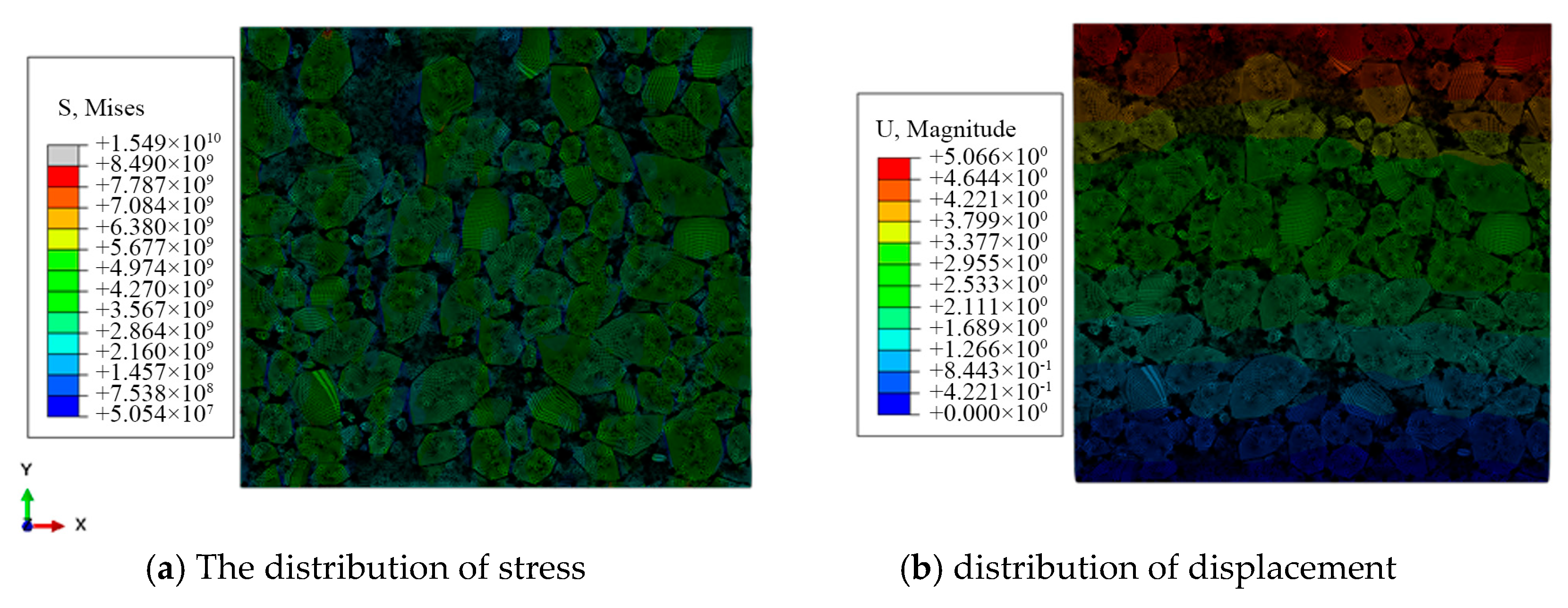
Figure 12a shows the stress distribution, and it is found that the stress is obviously concentrated at the interface between the particles and the matrix, which is closely related to the existence of the ITZ.
Figure 12b shows the displacement distribution of the composite material under uniaxial compression. It is found that the displacement in the upper layer is the largest in the loading direction and zero in the bottom layer.
Figure 12a shows the stress distribution, and it can be seen that the stress is obviously concentrated at the interface between the particles and the matrix, which is closely related to the existence of the ITZ. These results show that the introduction of the ITZ causes the simulation results to more closely mirror the mechanical behavior of actual concrete materials.
4. Discussion
This work proposed a novel method for generating multi-phase concrete-like composites. The above contents have already indicated the capability of this method. Here, the performance of this solution is discussed by giving different settings and parameters. The four influence factors, namely the boundary condition, minimum gap distance, ITZ thickness, and volume fraction, are discussed in this section.
4.1. Effect of ITZ Parameter
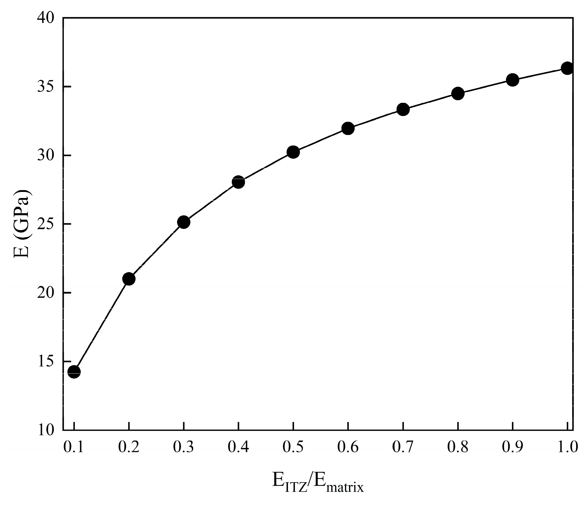
The elastic modulus of concrete materials under different ITZ parameters is calculated via numerical simulation. Ratios of
from 0.1 to 1 are employed, and the effective elastic modulus is shown in
Figure 13. The results show that the ITZ parameters have a significant effect on the elastic modulus of concrete materials, and the elastic modulus increases with the increase in ITZ parameters. The ITZ is the interface between the aggregate and cement paste, and its characteristics affect the overall performance of concrete materials. By understanding how ITZ parameters affect the elastic modulus, researchers can better predict and control the behavior of concrete-like materials under different loading conditions.
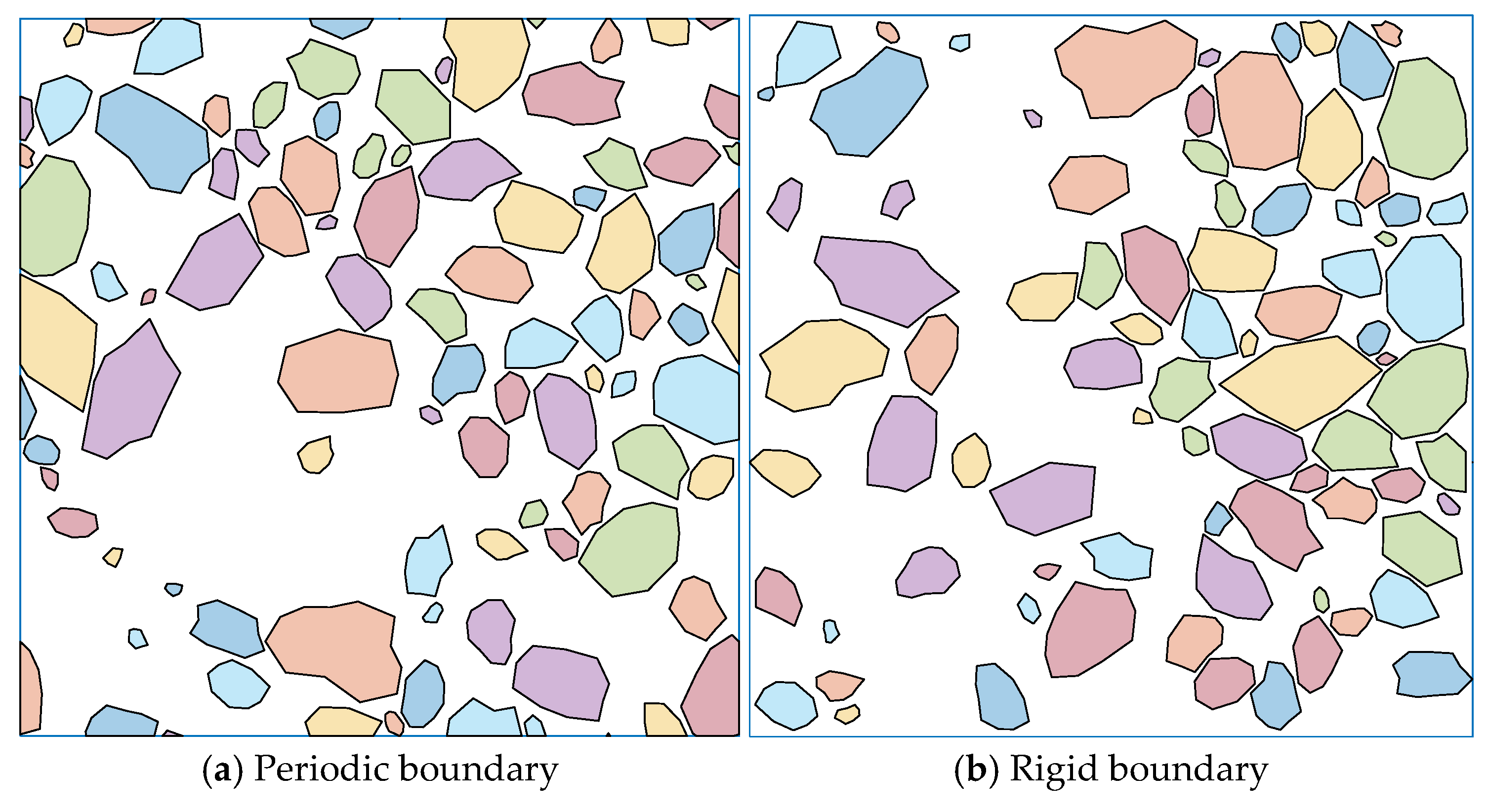
4.2. Performance of Different Boundary Conditions
The border effect (whether the aggregates can or cannot be located at the border) influences the physical behavior of concrete-like materials. In this method, the different boundary condition settings in the DEM simulation can affect the model structure. Mesoscale models with different boundary conditions are generated using the same grading information. In this case, the volume fraction is 45% with a minimum gap of 0.25 mm. Concrete-like composites generated using periodic and rigid boundary conditions are shown in
Figure 14. Compared with previous studies [
18,
27], this method has obvious advantages regarding the periodic mesostructure without extra computation.
The parameters of concrete materials under different boundary conditions are calculated using numerical simulation. The calculation results are shown in
Table 5. For periodic boundary conditions, the elastic modulus is 23.77 GPa and Poisson’s ratio is 0.17. Under the rigid boundary condition, the elastic modulus increases to 27.75 GPa and Poisson’s ratio increases to 0.19. Periodic boundary conditions allow for a more uniform stress distribution, while rigid boundaries introduce a higher stress concentration, resulting in higher calculated values of elastic modulus and Poisson’s ratio. The numerical simulation results provide valuable insight into the behavior of concrete-like materials and can be used to improve and enhance the accuracy of future simulations and experiments.
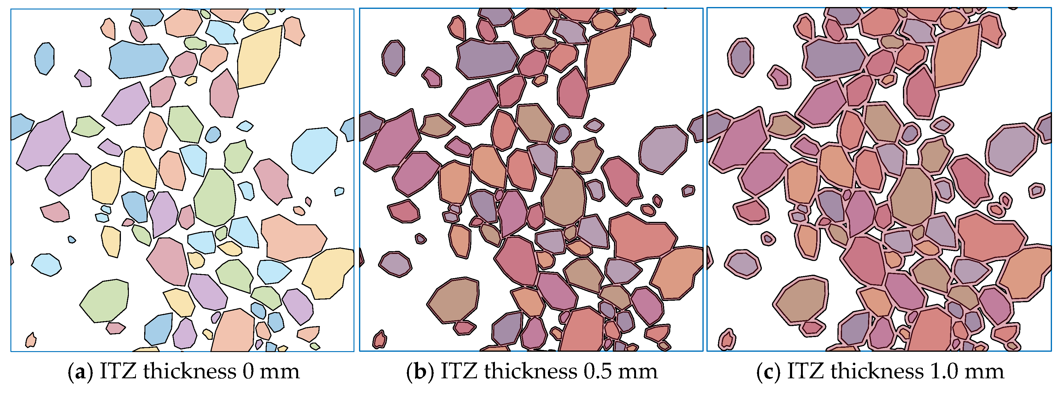
4.3. Performance of Different ITZ Thicknesses
The ITZ is an important component of concrete-like material and seriously impacts the whole set of physical properties. When the gap between the aggregates is smaller than the ITZ thickness, there are overlapped ITZs that introduce difficulty into the analysis. An accurate Minkowski sum-based ITZ computation is presented in this method. A case with a volume fraction of 40% and a minimum gap distance of 0.25 mm is employed to show the performance of this method with different ITZ thicknesses (
Figure 15). With an increase in the thickness, the overlapped area of the ITZ grows and a connected region from top to bottom is formed. This indicates that this method is capable of analyzing ITZ properties and can explain many physical behaviors, like percolation.
The results of concrete materials under different ITZ thicknesses are calculated by numerical simulation. The calculation results are shown in
Table 6. As the ITZ thickness increases from 0 mm to 1 mm, the elastic modulus of the concrete material shows a downward trend, while Poisson’s ratio remains relatively stable, indicating that the ITZ thickness has a significant effect on the elastic modulus of the material. This is mainly because the ITZ is usually weaker than cement mortar and has lower strength.
5. Conclusions
In this study, an innovative DEM-enhanced force-free method is proposed for multi-phase mesoscale modeling of high-volume-fraction composites. By using the Minkowski sum theory, this method can accurately calculate the ITZ. It allows for more flexible control of the minimum gap between the aggregate and ITZ thickness. Theoretically, this method can be adapted to any aggregate shape. By setting different boundary conditions, various boundary types can be realized. It is suggested that the minimum gap distance should be used as a parameter to adjust the uniformity of aggregate distribution. In addition, this method is helpful when generating a mesoscale model with a volume fraction of more than 80% and a controlled ITZ thickness. The performance of the method under different settings and parameters proves the feasibility of analyzing complex mesoscale structures. As a multifunctional technology, this work has great application potential in future structural optimization and material design.
However, the limitations of this study must be recognized. DEM simulation is based on multiple assumptions, such as a simplified representation of particle interactions and the idealization of some physical phenomena. These assumptions may lead to differences between the simulation results and the actual scene.
In the future, multi-scale coupling simulation should be developed to combine mesoscale models with macro-structure analysis to develop a more comprehensive understanding of the behavior of composite materials at different scales, which is helpful for the continuous improvement and wider application of the proposed DEM enhancement method in the field of composite materials.
Author Contributions
P.Q.: data curation, formal analysis, writing—original draft. L.Y.: investigation, validation, resources. C.H.: visualization, writing—original draft, conceptualization. J.H.: methodology, supervision, writing. Q.M.: review and editing. All authors have read and agreed to the published version of the manuscript.
Funding
This study is financially supported by the Key Laboratory of Rock Mechanics and Geohazards of Zhejiang Province (Grant No. ZJRMG-2021-02).
Data Availability Statement
The original contributions presented in this study are included in the article. Further inquiries can be directed to the corresponding authors.
Conflicts of Interest
Authors Lei Yang and Chengjia Huang were employed by the company PowerChina Huadong Engineering Corporation. The remaining authors declare that the research was conducted in the absence of any commercial or financial relationships that could be construed as a potential conflict of interest.
References
- Zhang, H.; Sheng, P.; Zhang, J.; Ji, Z. Realistic 3D modeling of concrete composites with randomly distributed aggregates by using aggregate expansion method. Constr. Build. Mater. 2019, 225, 927–940. [Google Scholar] [CrossRef]
- Ren, W.; Yang, Z.; Sharma, R.; Zhang, C.; Withers, P.J. Two-dimensional X-ray CT image based meso-scale fracture modelling of concrete. Eng. Fract. Mech. 2015, 133, 24–39. [Google Scholar] [CrossRef]
- Meng, Q.-X.; Wang, H.L.; Xu, W.Y.; Zhang, Q. A coupling method incorporating digital image processing and discrete element method for modeling of geomaterials. Eng. Comput. 2018, 35, 411–431. [Google Scholar] [CrossRef]
- Huang, Y.; Yan, D.; Yang, Z.; Liu, G. 2D and 3D homogenization and fracture analysis of concrete based on in-situ X-ray Computed Tomography images and Monte Carlo simulations. Eng. Fract. Mech. 2016, 163, 37–54. [Google Scholar] [CrossRef]
- Trawiński, W.; Bobiński, J.; Tejchman, J. Two-dimensional simulations of concrete fracture at aggregate level with cohesive elements based on X-ray μCT images. Eng. Fract. Mech. 2016, 168, 204–226. [Google Scholar] [CrossRef]
- Nitka, M.; Tejchman, J. A three-dimensional meso-scale approach to concrete fracture based on combined DEM with X-ray μCT images. Cem. Concr. Res. 2018, 107, 11–29. [Google Scholar] [CrossRef]
- Yang, Z.; Ren, W.; Sharma, R.; McDonald, S.; Mostafavi, M.; Vertyagina, Y.; Marrow, T.J. In-situ X-ray computed tomography characterisation of 3D fracture evolution and image-based numerical homogenisation of concrete. Cem. Concr. Compos. 2017, 75, 74–83. [Google Scholar] [CrossRef]
- Meng, Q.-X.; Xu, W.-Y.; Wang, H.-L.; Zhuang, X.-Y.; Xie, W.-C.; Rabczuk, T. DigiSim—An Open Source Software Package for Heterogeneous Material Modeling Based on Digital Image Processing. Adv. Eng. Softw. 2020, 148, 102836. [Google Scholar] [CrossRef]
- Bazant, Z.P.; Tabbara, M.R.; Kazemi, M.T.; Pijaudier-Cabot, G. Random particle model for fracture of aggregate or fiber composites. J. Eng. Mech. 1990, 116, 1686–1705. [Google Scholar] [CrossRef]
- Wang, Z.; Kwan, A.; Chan, H. Mesoscopic study of concrete I: Generation of random aggregate structure and finite element mesh. Comput. Struct. 1999, 70, 533–544. [Google Scholar] [CrossRef]
- Wriggers, P.; Moftah, S.O. Mesoscale models for concrete: Homogenisation and damage behaviour. Finite Elem. Anal. Des. 2006, 42, 623–636. [Google Scholar] [CrossRef]
- Gal, E.; Ganz, A.; Hadad, L.; Kryvoruk, R. Development of a Concrete Unit Cell. Int. J. Multiscale Comput. Eng. 2008, 6, 499–510. [Google Scholar] [CrossRef]
- Wang, X.F.; Yang, Z.J.; Yates, J.R.; Jivkov, A.P.; Zhang, C. Monte Carlo simulations of mesoscale fracture modelling of concrete with random aggregates and pores. Constr. Build. Mater. 2015, 75, 35–45. [Google Scholar] [CrossRef]
- Zhang, J.; Wang, Z.; Yang, H.; Wang, Z.; Shu, X. 3D meso-scale modeling of reinforcement concrete with high volume fraction of randomly distributed aggregates. Constr. Build. Mater. 2018, 164, 350–361. [Google Scholar] [CrossRef]
- Wittmann, F.; Roelfstra, P.; Sadouki, H. Simulation and analysis of composite structures. Mater. Sci. Eng. 1985, 68, 239–248. [Google Scholar] [CrossRef]
- Meng, Q.; Wang, H.; Cai, M.; Xu, W.; Zhuang, X.; Rabczuk, T. Three-dimensional mesoscale computational modeling of soil-rock mixtures with concave particles. Eng. Geol. 2020, 277, 105802. [Google Scholar] [CrossRef]
- Ma, H.; Xu, W.; Li, Y. Random aggregate model for mesoscopic structures and mechanical analysis of fully-graded concrete. Comput. Struct. 2016, 177, 103–113. [Google Scholar] [CrossRef]
- Meng, Q.-X.; Lv, D.; Liu, Y. Mesoscale computational modeling of concrete-like particle-reinforced composites with non-convex aggregates. Comput. Struct. 2020, 240, 106349. [Google Scholar] [CrossRef]
- De Schutter, G.; Taerwe, L. Random particle model for concrete based on Delaunay triangulation. Mater. Struct. 1993, 26, 67–73. [Google Scholar] [CrossRef]
- Mollon, G.; Zhao, J. Fourier–Voronoi-based generation of realistic samples for discrete modelling of granular materials. Granul. Matter 2012, 14, 621–638. [Google Scholar] [CrossRef]
- Mollon, G.; Zhao, J. Generating realistic 3D sand particles using Fourier descriptors. Granul. Matter 2012, 15, 95–108. [Google Scholar] [CrossRef]
- Sheng, P.; Zhang, J.; Ji, Z. An advanced 3D modeling method for concrete-like particle-reinforced composites with high volume fraction of randomly distributed particles. Compos. Sci. Technol. 2016, 134, 26–35. [Google Scholar] [CrossRef]
- Zhuang, X.; Wang, Q.; Zhu, H. Effective Properties of Composites with Periodic Random Packing of Ellipsoids. Materials 2017, 10, 112. [Google Scholar] [CrossRef] [PubMed]
- Garcia-Hernandez, A.; Wan, L.; Dopazo-Hilario, S.; Chiarelli, A.; Dawson, A. Generation of virtual asphalt concrete in a physics engine. Constr. Build. Mater. 2021, 286, 122972. [Google Scholar] [CrossRef]
- Du, C.-B.; Sun, L.-G. Numerical Simulation of Aggregate Shapes of Two-Dimensional Concrete and Its Application. J. Aerospace Eng. 2007, 20, 172–178. [Google Scholar] [CrossRef]
- Xu, W.J.; Hu, L.M.; Gao, W. Random generation of the meso-structure of a soil-rock mixture and its application in the study of the mechanical behavior in a landslide dam. Int. J. Rock. Mech. Min. 2016, 86, 166–178. [Google Scholar] [CrossRef]
- Meng, Q.-X.; Wang, H.L.; Xu, W.Y.; Cai, M. A numerical homogenization study of the elastic property of a soil-rock mixture using random mesostructure generation. Comput. Geotech. 2018, 98, 48–57. [Google Scholar] [CrossRef]
- Bowman, E.T.; Soga, K.; Drummond, W. Particle shape characterisation using Fourier descriptor analysis. Geotechnique 2001, 51, 545–554. [Google Scholar] [CrossRef]
- Garboczi, E.J. Three-dimensional mathematical analysis of particle shape using X-ray tomography and spherical harmonics: Application to aggregates used in concrete. Cem. Concr. Res. 2002, 32, 1621–1638. [Google Scholar] [CrossRef]
- Agarwal, P.K.; Flato, E.; Halperin, D. Polygon decomposition for efficient construction of Minkowski sums. Comput. Geom. 2002, 21, 39–61. [Google Scholar] [CrossRef]
- Fabri, A.; Pion, S. CGAL: The Computational Geometry Algorithms Library. In Proceedings of the 17th ACM SIGSPATIAL International Conference on Advances in Geographic Information Systems, Association for Computing Machinery, Seattle, WA, USA, 4–6 November 2009; pp. 538–539. [Google Scholar]
- Walraven, J.C. Aggregate Interlock; Delft University Press: Delft, The Netherlands, 1980. [Google Scholar]
- Cundall, P.A.; Strack, O.D.L. A discrete numerical model for granular assemblies. Geotechnique 1979, 29, 47–65. [Google Scholar] [CrossRef]
- Wang, L.; Park, J.-Y.; Fu, Y. Representation of real particles for DEM simulation using X-ray tomography. Constr. Build. Mater. 2007, 21, 338–346. [Google Scholar] [CrossRef]
- Matsushima, T.; Saomoto, H.; Matsumoto, M.; Toda, K.; Yamada, Y. Discrete element simulation of an assembly of irregularly-shaped grains: Quantitative comparison with experiments. In Proceedings of the 16th ASCE Engineering Mechanics Conference, Seattle, WA, USA, 16–18 July 2003; American Society of Civil Engineers: Reston, VA, USA, 2003. [Google Scholar]
- Ferellec, J.-F.; McDowell, G.R. A method to model realistic particle shape and inertia in DEM. Granul. Matter 2010, 12, 459–467. [Google Scholar] [CrossRef]
- Angelidakis, V.; Boschi, K.; Brzeziński, K.; Caulk, R.A.; Chareyre, B.; del Valle, C.A.; Duriez, J.; Gladky, A.; van der Haven, D.L.H.; Kozicki, J.; et al. YADE—An extensible framework for the interactive simulation of multiscale, multiphase, and multiphysics particulate systems. Comput. Phys. Commun. 2024, 304, 109293. [Google Scholar] [CrossRef]
- Liu, Y.; Zhou, X.; You, Z.; Yao, S.; Gong, F.; Wang, H. Discrete element modeling of realistic particle shapes in stone-based mixtures through MATLAB-based imaging process. Constr. Build. Mater. 2017, 143, 169–178. [Google Scholar] [CrossRef]
- Cundall, P. PFC2D User’s Manual (Version 5.0); Itasca Consulting Group Inc.: Minnesota, MN, USA, 2015; p. 325. [Google Scholar]
- Ding, Y.; Zhang, Q.; Zha, S.; Chu, W.; Meng, Q. An improved DEM-based mesoscale modeling of bimrocks with high-volume fraction. Comput. Geotech. 2023, 157, 105351. [Google Scholar] [CrossRef]
- Xu, Y.; Chen, S. A method for modeling the damage behavior of concrete with a three-phase mesostructured. Constr. Build. Mater. 2016, 102, 26–38. [Google Scholar] [CrossRef]
- Wang, X.; Yang, Z.; Jivkov, A.P. Monte Carlo simulations of mesoscale fracture of concrete with random aggregates and pores: A size effect study. Constr. Build. Mater. 2015, 80, 262–272. [Google Scholar] [CrossRef]
- Xu, W.; Jiao, Y. Theoretical framework for percolation threshold, tortuosity and transport properties of porous materials containing 3D non-spherical pores. Int. J. Eng. Sci. 2019, 134, 31–46. [Google Scholar] [CrossRef]
- Xu, W.; Jia, M.; Gong, Z. Thermal conductivity and tortuosity of porous composites considering percolation of porous network: From spherical to polyhedral pores. Compos. Sci. Technol. 2018, 167, 134–140. [Google Scholar] [CrossRef]
- GB50107-2010; Standard for Test and Evaluation of Concrete Strength. China Architecture & Building Press: Beijing, China, 2010.
- Li, S.; Li, Q. Method of meshing ITZ structure in 3D meso-level finite element analysis for concrete. Finite Elem. Anal. Des. 2015, 93, 96–106. [Google Scholar]
Figure 1.
Flowchart for mesoscale modeling of multi-phase concrete.
Figure 1.
Flowchart for mesoscale modeling of multi-phase concrete.
Figure 2.
Methods for generating rock aggregates.
Figure 2.
Methods for generating rock aggregates.
Figure 3.
Thickness offset of the aggregate using Minkowski sum.
Figure 3.
Thickness offset of the aggregate using Minkowski sum.
Figure 4.
Illustration of the ODECs generation algorithm. (
a) Expansion of a disk [
36]; (
b) example of cluster generation.
Figure 4.
Illustration of the ODECs generation algorithm. (
a) Expansion of a disk [
36]; (
b) example of cluster generation.
Figure 5.
Illustration of the placement of clumps.
Figure 5.
Illustration of the placement of clumps.
Figure 6.
Illustration of the periodic boundary condition.
Figure 6.
Illustration of the periodic boundary condition.
Figure 7.
Final aggregate based on the translation and rotation transformation.
Figure 7.
Final aggregate based on the translation and rotation transformation.
Figure 8.
The addition of ghost aggregates for periodic structure.
Figure 8.
The addition of ghost aggregates for periodic structure.
Figure 9.
The union of overlapped ITZs.
Figure 9.
The union of overlapped ITZs.
Figure 10.
Periodic meshing of the trimmed aggregate domain.
Figure 10.
Periodic meshing of the trimmed aggregate domain.
Figure 11.
The whole generation of multi-phase concrete.
Figure 11.
The whole generation of multi-phase concrete.
Figure 12.
FEM numerical simulation result for multiphase concretes.
Figure 12.
FEM numerical simulation result for multiphase concretes.
Figure 13.
The variation curve of elastic modulus with ITZ parameter.
Figure 13.
The variation curve of elastic modulus with ITZ parameter.
Figure 14.
Effect of boundary conditions on the mesoscale model.
Figure 14.
Effect of boundary conditions on the mesoscale model.
Figure 15.
Mesoscale model with different ITZ thicknesses.
Figure 15.
Mesoscale model with different ITZ thicknesses.
Table 1.
The grading information of coarse aggregate.
Table 1.
The grading information of coarse aggregate.
| Sieve Size (mm) | Total Percentage Retained (%) | Total Percentage Passing (%) |
|---|
| 12.70 | 0.0 | 100.0 |
| 9.50 | 39.0 | 61.0 |
| 4.75 | 90.0 | 10.0 |
| 2.36 | 98.6 | 1.4 |
Table 2.
The contact parameters in DEM simulation.
Table 2.
The contact parameters in DEM simulation.
| Density (kg/m3) | Stiffness(N/m) | Friction Coefficient | Damping Ratio |
|---|
| Normal | Tangential |
|---|
| 2650 | 5 × 10⁸ | 5 × 10⁸ | 0 | 0.5 |
Table 3.
Model material parameters.
Table 3.
Model material parameters.
| | E (GPa) | | Vpar (%) |
|---|
| Matrix | 19.20 | 0.20 | |
| Particles | 61.90 | 0.15 | 57 |
| ITZ | 17.28 | 0.20 | |
Table 4.
Simulation and experimental comparison results.
Table 4.
Simulation and experimental comparison results.
| | Ec (GPa) | |
|---|
| Experimental data | 36.40 | - |
| Simulated data | 35.47 | 0.18 |
Table 5.
Simulation results under different boundary conditions.
Table 5.
Simulation results under different boundary conditions.
| Type of Boundary Conditions | E (GPa) | |
|---|
| Periodic boundary | 23.77 | 0.17 |
| Rigid boundary | 27.75 | 0.19 |
Table 6.
The simulation results under different ITZ thicknesses.
Table 6.
The simulation results under different ITZ thicknesses.
| ITZ Thickness (mm) | E (GPa) | |
|---|
| 0 | 25.10 | 0.17 |
| 0.5 | 24.24 | 0.17 |
| 1 | 23.77 | 0.17 |
| Disclaimer/Publisher’s Note: The statements, opinions and data contained in all publications are solely those of the individual author(s) and contributor(s) and not of MDPI and/or the editor(s). MDPI and/or the editor(s) disclaim responsibility for any injury to people or property resulting from any ideas, methods, instructions or products referred to in the content. |
© 2025 by the authors. Licensee MDPI, Basel, Switzerland. This article is an open access article distributed under the terms and conditions of the Creative Commons Attribution (CC BY) license (https://creativecommons.org/licenses/by/4.0/).


