
Investigation on the Buckling Behavior of Normal Steel CHS Beam–Columns: A Revised Design Approach with Reliability Analysis


Abstract
1. Introduction
2. Buckling Resistance of CHS Beam–Columns
2.1. The prEN 1993-1-1 Design Provisions
2.2. Revised Buckling Design Approach
3. Finite Element Model
3.1. Development
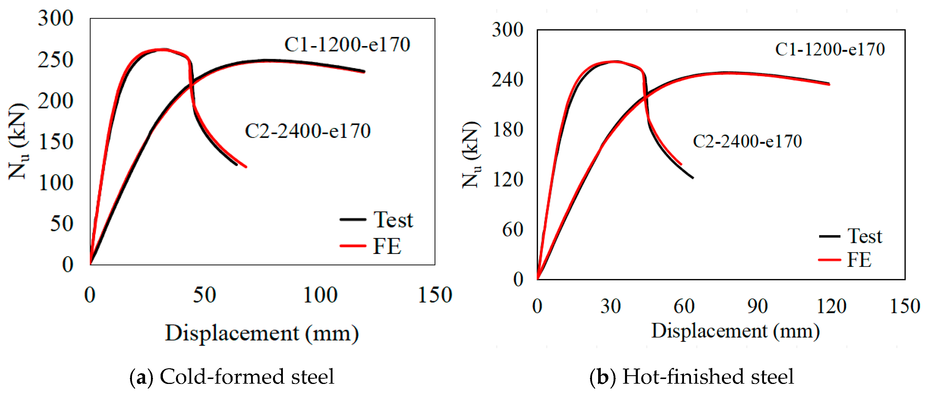
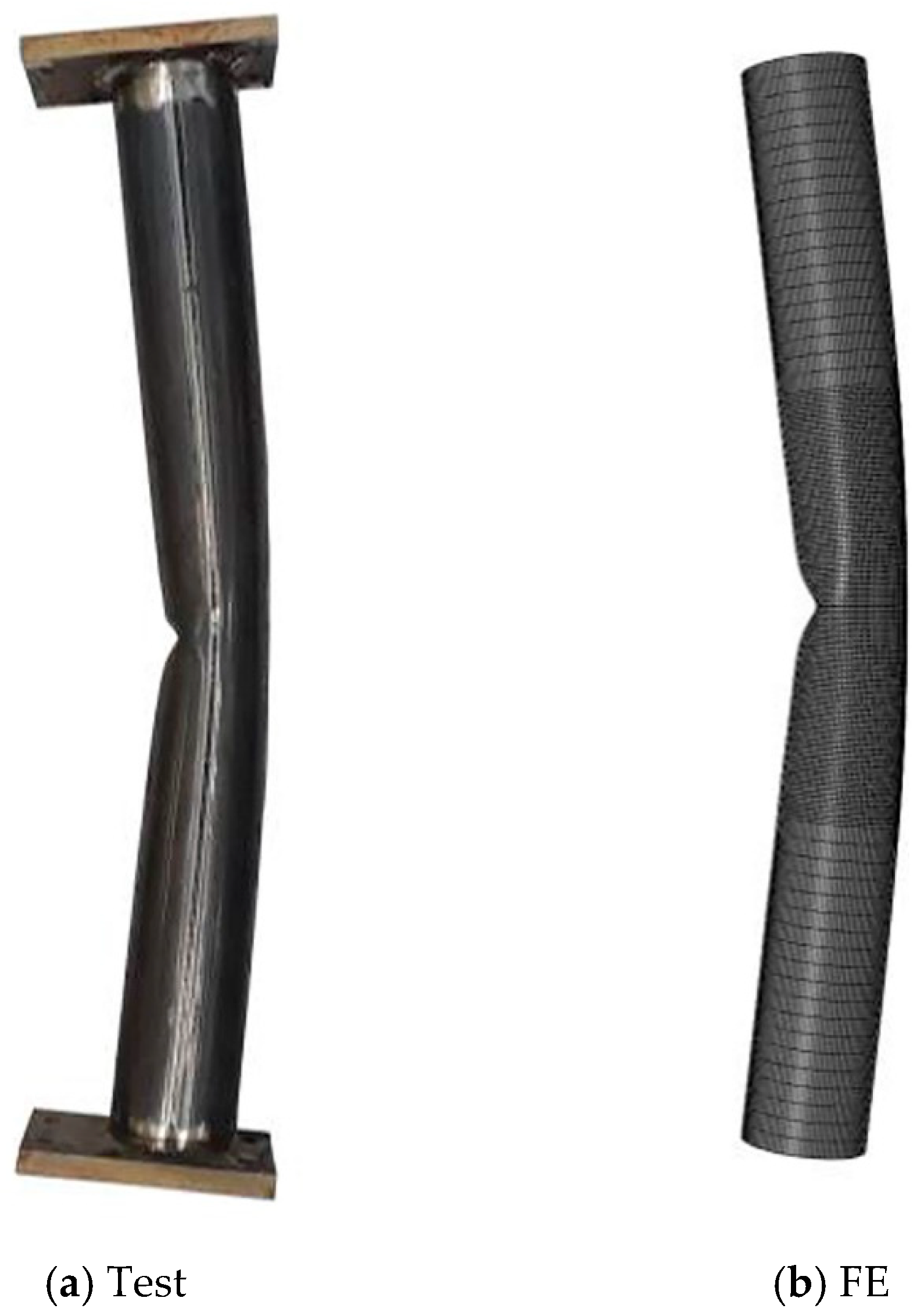
3.2. Validation
3.3. Parametric Studies
4. Results and Discussion
4.1. Cold-Formed Sections
4.2. Hot-Finished Sections
5. Reliability Analysis
6. Conclusions
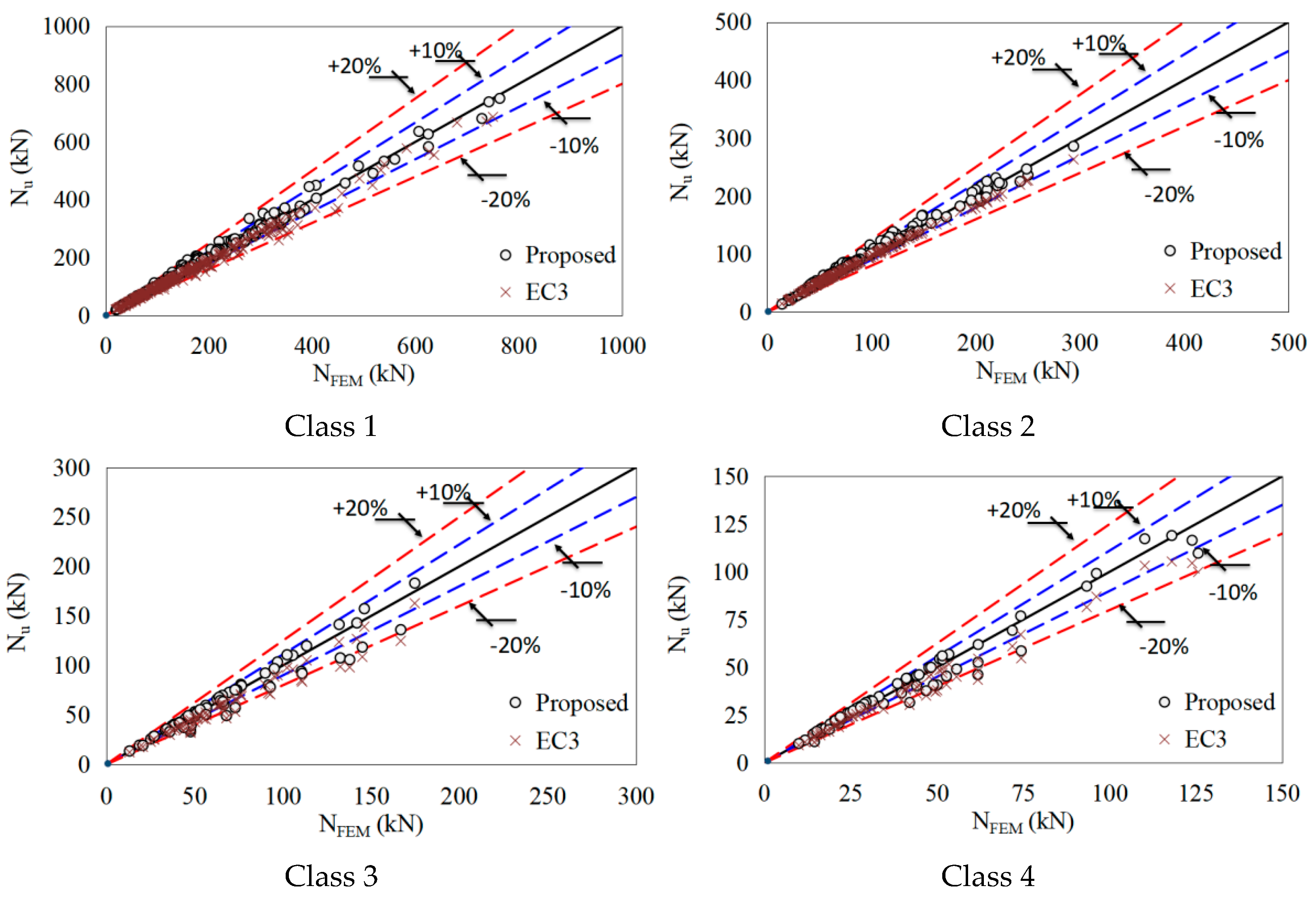
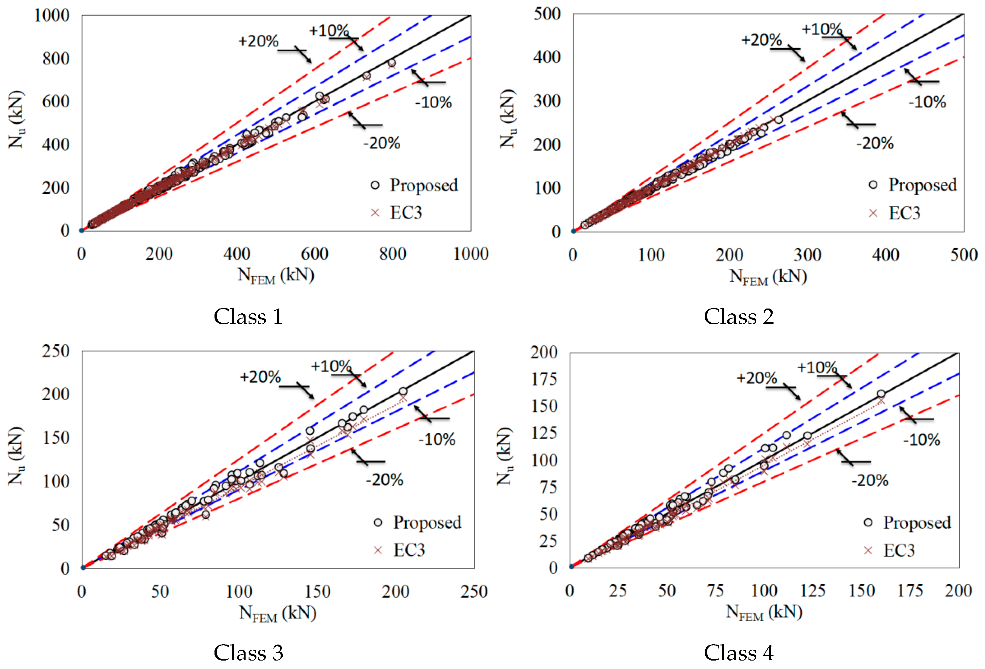
- The existing design provisions in Eurocode 3 clearly underestimate the buckling resistance of CHS beam–columns, with an acceptable level of accuracy for both cold-formed and hot-finished sections. On the other hand, the proposed buckling design approach provides more accurate and consistent resistance predictions compared with Eurocode 3;
- For Eurocode 3, the mean predicted-to-design ratio and RMSE are 0.98 and 11.8 kN for Class 1–2 sections, and 0.91 and 8.4 kN for Class 3–4 sections, respectively;
- For the proposed approach, these values are 0.99 and 8.1 kN for Class 1–2 sections and 1.00 and 6.4 kN for Class 3–4 sections, respectively;
- The reliability analysis suggests a partial safety factor of 1.138 for Eurocode 3 and a slightly lower value of 1.121 for the proposed approach, providing less conservatism in the prediction of the buckling resistance of CHS beam–columns.
Funding
Data Availability Statement
Acknowledgments
Conflicts of Interest
References
- Buchanan, C.; Real, E.; Gardner, L. Testing, simulation and design of cold-formed stainless steel CHS columns. Thin-Walled Struct. 2018, 130, 297–312. [Google Scholar] [CrossRef]
- Xing, Z.; Jiang, M.; San, B.; Wang, J.; Wu, K. Fire behaviour of stainless steel circular hollow section stub columns: Experimental study and design. Thin-Walled Struct. 2024, 196, 111494. [Google Scholar] [CrossRef]
- Rabi, M.; Cashell, K.A.; Shamass, R. Analysis of concrete beams reinforced with stainless steel. In Proceedings of the fib Symposium 2019: Concrete-Innovations in Materials, Design and Structures, Krakow, Poland, 27–29 May 2019; pp. 690–697. [Google Scholar]
- Baddoo, N.; Chen, A. High Strength Steel Design and Execution Guide. SCI—The Steel Construction Institute: Ascot, UK, 2020. [Google Scholar]
- Rabi, M.; Ferreira, F.P.V.; Abarkan, I.; Limbachiya, V.; Shamass, R. Prediction of the cross-sectional capacity of cold-formed CHS using numerical modelling and machine learning. Results Eng. 2023, 17, 100902. [Google Scholar] [CrossRef]
- Rabi, M.; Abarkan, I.; Shamass, R. Buckling resistance of hot-finished CHS beam-columns using FE modelling and machine learning. Steel Constr. 2024, 17, 93–103. [Google Scholar] [CrossRef]
- Sperle, J.; Hallberg, L.; Larsson, J.; Groth, H.; Östman, K.; Larsson, J. The environmental value of high strength steel structures. In Environmental Research Programme for the Swedish Steel Industry, The Steel Eco-Cycle; Jernkontoret: Stockholm, Sweden, 2013; Report No. 88044; pp. 151–171. [Google Scholar]
- Abarkan, I.; Rabi, M.; Ferreira, F.P.V.; Shamass, R.; Limbachiya, V.; Jweihan, Y.S.; Santos, L.F.P. Machine learning for optimal design of circular hollow section stainless steel stub columns: A comparative analysis with Eurocode 3 predictions. Eng. Appl. Artif. Intell. 2024, 132, 107952. [Google Scholar] [CrossRef]
- Wang, J.; Shu, G.; Zheng, B.; Jiang, Q. Investigations on cold-forming effect of cold-drawn duplex stainless steel tubular sections. J. Constr. Steel Res. 2019, 152, 81–93. [Google Scholar] [CrossRef]
- Liu, J.Z.; Fang, H.; Chan, T.M. Investigations on material properties and residual stresses in cold-formed high strength steel irregular hexagonal hollow sections. Thin-Walled Struct. 2022, 176, 109220. [Google Scholar] [CrossRef]
- Yun, X.; Gardner, L. Stress-strain curves for hot-rolled steels. J. Constr. Steel Res. 2017, 133, 36–46. [Google Scholar] [CrossRef]
- Rabi, M. Bond prediction of stainless-steel reinforcement using artificial neural networks. Proc. Inst. Civ. Eng.-Constr. Mater. 2023, 177, 87–97. [Google Scholar] [CrossRef]
- Rabi, M.; Cashell, K.A.; Shamass, R.; Desnerck, P. Bond behaviour of austenitic stainless steel reinforced concrete. Eng. Struct. 2020, 221, 111027. [Google Scholar] [CrossRef]
- Huang, C.; Meng, X.; Buchanan, C.; Gardner, L. Flexural buckling of wire arc additively manufactured tubular columns. J. Struct. Eng. 2022, 148, 04022139. [Google Scholar] [CrossRef]
- Hussein, D.B.; Hussein, A.B. Investigating the Factors Influencing the Strength of Cold-Formed Steel (CFS) Sections. Buildings 2024, 14, 1127. [Google Scholar] [CrossRef]
- Rabi, M.; Shamass, R.; Cashell, K.A. Description of the constitutive behaviour of stainless steel reinforcement. Case Stud. Constr. Mater. 2024, 20, e03013. [Google Scholar] [CrossRef]
- Rabi, M.; Shamass, R.; Cashell, K.A. Structural performance of stainless steel reinforced concrete members: A review. Constr. Build. Mater. 2022, 325, 126673. [Google Scholar] [CrossRef]
- Rabi, M.; Shamass, R.; Cashell, K.A. Experimental investigation on the flexural behaviour of stainless steel reinforced concrete beams. Struct. Infrastruct. Eng. 2023, 19, 1847–1859. [Google Scholar] [CrossRef]
- prEN 1993-1-1:2020; Eurocode 3—Design of Steel Structures—Part 1-1: General Rules and Rules for Buildings, Final Document. European Committee for Standardization (CEN): Brussels, Belgium, 2020.
- Lan, X.; Chen, J.; Chan, T.M.; Young, B. The continuous strength method for the design of high strength steel tubular sections in compression. Eng. Struct. 2018, 162, 177–187. [Google Scholar] [CrossRef]
- Rabi, M.; Jweihan, Y.S.; Abarkan, I.; Ferreira, F.P.V.; Shamass, R.; Limbachiya, V.; Tsavdaridis, K.D.; Santos, L.F.P. Machine learning-driven web-post buckling resistance prediction for high-strength steel beams with elliptically-based web openings. Results Eng. 2024, 21, 101749. [Google Scholar] [CrossRef]
- Taras, A.; Greiner, R.; Unterweger, H. Proposal for amended rules for member buckling and semi-compact cross-section design. Technical report, Consolidated version of documents of the same title submitted to the SC3 Evolution Group 1993-1-1, Paris. 2013. [Google Scholar]
- Xiong, M.X.; Xiong, D.X.; Liew, J.R. Axial performance of short concrete filled steel tubes with high-and ultra-high-strength materials. Eng. Struct. 2017, 136, 494–510. [Google Scholar] [CrossRef]
- Teng, J.G.; Hu, Y.M. Behaviour of FRP-jacketed circular steel tubes and cylindrical shells under axial compression. Constr. Build. Mater. 2007, 21, 827–838. [Google Scholar] [CrossRef]
- Kamba, T. Stub column test of high-strength CHS steel column with small diameter-to-thickness ratio. In Tubular Structures VII; Routledge: London, UK, 1996; pp. 397–404. [Google Scholar]
- Kato, M.; Warizawa, T.; Suzuki, T.; Ogawa, T. Structural properties of high strength structural steel tubes. Trans. Iron Steel Inst. Jpn. 1984, 24, 147–155. [Google Scholar] [CrossRef]
- Toi, Y.; Ine, T. Basic Studies on the Crashworthiness of Structural Elements (Part 5) Axisymmetric crush tests of circular cylinders and finite element analysis. J. Soc. Nav. Archit. Jpn. 1988, 1988, 406–419. [Google Scholar] [CrossRef] [PubMed]
- Ma, J.L.; Chan, T.M.; Young, B. Experimental investigation on stub-column behavior of cold-formed high-strength steel tubular sections. J. Struct. Eng. 2016, 142, 04015174. [Google Scholar] [CrossRef]
- Zhao, X.L. Section capacity of very high strength (VHS) circular tubes under compression. Thin-Walled Struct. 2000, 37, 223–240. [Google Scholar] [CrossRef]
- Jiao, H.; Zhao, X.L. Imperfection, residual stress and yield slenderness limit of very high strength (VHS) circular steel tubes. J. Constr. Steel Res. 2003, 59, 233–249. [Google Scholar] [CrossRef]
- Zhao, X.L.; Tong, L.W.; Wang, X.Y. CFDST stub columns subjected to large deformation axial loading. Eng. Struct. 2010, 32, 692–703. [Google Scholar] [CrossRef]
- Sakino, K.; Nakahara, H.; Morino, S.; Nishiyama, I. Behavior of centrally loaded concrete-filled steel-tube short columns. J. Struct. Eng. 2004, 130, 180–188. [Google Scholar] [CrossRef]
- Sherman, D.R. Inelastic flexural buckling of cylinders. In Steel Structures: Recent Research Advances and Their Applications to Design; Pavlovic, M.N., Ed.; Elsevier Applied Science Publishers: Amsterdam, The Netherlands, 1986; pp. 339–357. [Google Scholar]
- Prasad, J. Hollow Structural Sections in Flexure. Doctoral Dissertation, McMaster University, Hamilton, ON, Canada, 1972. [Google Scholar]
- Ning, K.; Yang, L.; Sun, Y.; Sun, Y. Testing, simulation and design of hot-rolled seamless austenitic stainless steel CHS columns. In Structures; Elsevier: Amsterdam, The Netherlands, 2022; Volume 40, pp. 295–302. [Google Scholar]
- Sherman, D.R. Tests of circular steel tubes in bending. J. Struct. Div. 1976, 102, 2181–2195. [Google Scholar] [CrossRef]
- Sedlacek, G.; Dahl, W.; Stranghöner, N.; Kalinowski, B.; Rondal, J.; Boeraeve, P.H. Investigation of the Rotation Behaviour of Hollow Section Beams; EUR: Luxembourg, 1995. [Google Scholar]
- Jiao, H.; Zhao, X.L. Section slenderness limits of very high strength circular steel tubes in bending. Thin-Walled Struct. 2004, 42, 1257–1271. [Google Scholar] [CrossRef]
- Ma, J.L.; Chan, T.M.; Young, B. Experimental investigation of cold-formed high strength steel tubular beams. Eng. Struct. 2016, 126, 200–209. [Google Scholar] [CrossRef]
- Elchalakani, M.; Zhao, X.L.; Grzebieta, R. Bending tests to determine slenderness limits for cold-formed circular hollow sections. J. Constr. Steel Res. 2002, 58, 1407–1430. [Google Scholar] [CrossRef]
- Gardner, L.; Chan, T.M. Cross-section classification of elliptical hollow sections. Steel Compos. Struct. 2007, 7, 185. [Google Scholar] [CrossRef]
- Khalaf, M.S.; Ibrahim, A.M.; Najm, H.M.; Sabri, M.M.S.; Morkhade, S.; Agarwal, A.; Alamir, M.A.; Alarifi, I.M. Experimental analysis of steel circular hollow section under bending loads: Comprehensive study of mechanical performance. Materials 2022, 15, 4350. [Google Scholar] [CrossRef] [PubMed]
- Meng, X.; Gardner, L.; Sadowski, A.J.; Rotter, J.M. Elasto-plastic behaviour and design of semi-compact circular hollow sections. Thin-Walled Struct. 2020, 148, 106486. [Google Scholar] [CrossRef]
- Nseir, J. Development of a New Design Method for the Cross-Section Capacity of Steel Hollow Sections. Doctoral Dissertation, Université de Liège, Liège, Belgium, 2015. [Google Scholar]
- O’Shea, M.D.; Bridge, R.Q. Local buckling of thin-walled circular steel sections with or without internal restraint. J. Constr. Steel Res. 1997, 41, 137–157. [Google Scholar] [CrossRef]
- Peen, W.Y.; Keong, C.K.; Hassanshahi, O. Behaviour of hollow circular section with multiple perforations under compression, flexure and torsion. Lat. Am. J. Solids Struct. 2019, 16, e169. [Google Scholar] [CrossRef]
- Chen, J.; Chan, T.M. Material properties and residual stresses of cold-formed high-strength-steel circular hollow sections. J. Constr. Steel Res. 2020, 170, 106099. [Google Scholar] [CrossRef]
- Lan, X.; Chen, J.; Chan, T.M.; Young, B. The continuous strength method for the design of high strength steel tubular sections in bending. J. Constr. Steel Res. 2019, 160, 499–509. [Google Scholar] [CrossRef]
- Ma, J.L.; Chan, T.M.; Young, B. 12.18: Experimental investigation on cold-formed high strength steel circular hollow sections under combined compression and bending. ce/papers 2017, 1, 3622–3630. [Google Scholar] [CrossRef]
- Ma, J.L.; Pandey, M.; Chan, T.M.; Young, B. Structural performance of cold-formed high-strength steel circular hollow sections under combined compression and bending. J. Struct. Eng. 2022, 148, 04022148. [Google Scholar] [CrossRef]
- Meng, X.; Gardner, L. Cross-sectional behaviour of cold-formed high strength steel CHS under combined axial compression and bending. In Proceedings of the 8th International Conference on Thin-Walled Structures, Lisbon, Portugal, 25–27 July 2018; pp. 24–27. [Google Scholar]
- Shaker, F.M.; Zarzor, K.; Gaawan, S.; Deifalla, A.; Salem, M. Evaluation of axial compression slenderness limits of high and ultra-high-strength steel circular hollow sections. Buildings 2022, 12, 1093. [Google Scholar] [CrossRef]
- Wang, Y.; Yang, H.; Wang, Y.; Su, A. Testing, numerical modelling and design of S890 and S960 ultra-high strength steel circular hollow sections under combined loading. Thin-Walled Struct. 2023, 192, 111102. [Google Scholar] [CrossRef]
- Ma, J.L.; Chan, T.M.; Young, B. Design of cold-formed high strength steel tubular beams. Eng. Struct. 2017, 151, 432–443. [Google Scholar] [CrossRef]
- Pournara, A.E.; Karamanos, S.A.; Mecozzi, E.; Lucci, A. Structural resistance of high-strength steel CHS members. J. Constr. Steel Res. 2017, 128, 152–165. [Google Scholar] [CrossRef]
- Su, A.; Yang, H.; Wang, Y.; Wang, Y. Experimental and numerical investigations of S960 hot-rolled ultra-high strength steel seamless circular hollow section beam–columns. Thin-Walled Struct. 2024, 200, 111909. [Google Scholar] [CrossRef]
- Hayeck, M.; Nseir, J.; Saloumi, E.; Boissonnade, N. Experimental characterization of steel tubular beam-columns resistance by means of the Overall Interaction Concept. Thin-Walled Struct. 2018, 128, 92–107. [Google Scholar] [CrossRef]
- Linzell, D.G.; Zureick, A.; Leon, R.T. Comparison of measured and predicted response of manufactured circular steel tubular members under concentric and eccentric compressive and tensile loads. Eng. Struct. 2003, 25, 1019–1031. [Google Scholar] [CrossRef]
- Prion, H.G.L.; Birkemoe, P.C. Beam-column behavior of fabricated steel tubular members. J. Struct. Eng. 1992, 118, 1213–1232. [Google Scholar] [CrossRef]
- Dassault Systèmes. Abaqus User’s Guide Manual [Computer Program]. 2016. Available online: https://www.3ds.com/products/simulia/abaqus (accessed on 15 May 2025).
- Meng, X.; Gardner, L. Stability and design of normal and high strength steel CHS beam-columns. Eng. Struct. 2022, 251, 113361. [Google Scholar] [CrossRef]
- Buchanan, C.; Gardner, L.; Liew, A. The continuous strength method for the design of circular hollow sections. J. Constr. Steel Res. 2016, 118, 207–216. [Google Scholar] [CrossRef]
- EN 1990: Eurocode; Basis of Structural Design. European Committee for Standardization: Brussels, Belgium, 2024.

| Class | ||
|---|---|---|
| Class 1–2 | ||
| Class 3–4 |
| Class | ||
|---|---|---|
| Class 1–2 | ||
| Class 3–4 |
| NFE/Ntest | ||||
|---|---|---|---|---|
| Measured ωg | ωg = Lcr/500 | ωg = Lcr/1000 | ωg = Lcr/2000 | |
| Mean | 0.982 | 0.956 | 0.970 | 0.980 |
| CoV | 0.027 | 0.034 | 0.030 | 0.026 |
| De/t | Lcr (mm) | fy (MPa) | e (mm) | |
|---|---|---|---|---|
| Mean | 34.9 | 2894.7 | 355 | 55.16 |
| Maximum | 84.9 | 5311.6 | 355 | 344.93 |
| Minimum | 10.0 | 522.0 | 355 | 2.70 |
| EC3 | Proposed | |||
|---|---|---|---|---|
| Class 1–2 | Class 3–4 | Class 1–2 | Class 3–4 | |
| Mean | 0.98 | 0.91 | 0.99 | 1.00 |
| SD | 0.05 | 0.07 | 0.04 | 0.09 |
| CoV | 0.05 | 0.08 | 0.04 | 0.09 |
| RMSE | 11.82 | 8.39 | 8.11 | 6.39 |
| Max relative error (%) | 6.61 | 1.41 | 7.6 | 11.3 |
| Min relative error (%) | −17.42 | −29.7 | −13.5 | −28.1 |
| Resistance Model | Vr | ||||
|---|---|---|---|---|---|
| EC3 | 1.031 | 3.04 | 1.64 | 0.092 | 1.138 |
| Revised buckling design approach | 0.996 | 3.04 | 1.64 | 0.082 | 1.121 |
Disclaimer/Publisher’s Note: The statements, opinions and data contained in all publications are solely those of the individual author(s) and contributor(s) and not of MDPI and/or the editor(s). MDPI and/or the editor(s) disclaim responsibility for any injury to people or property resulting from any ideas, methods, instructions or products referred to in the content. |
© 2025 by the author. Licensee MDPI, Basel, Switzerland. This article is an open access article distributed under the terms and conditions of the Creative Commons Attribution (CC BY) license (https://creativecommons.org/licenses/by/4.0/).
Share and Cite
Rabi, M. Investigation on the Buckling Behavior of Normal Steel CHS Beam–Columns: A Revised Design Approach with Reliability Analysis. Buildings 2025, 15, 1708. https://doi.org/10.3390/buildings15101708
Rabi M. Investigation on the Buckling Behavior of Normal Steel CHS Beam–Columns: A Revised Design Approach with Reliability Analysis. Buildings. 2025; 15(10):1708. https://doi.org/10.3390/buildings15101708
Chicago/Turabian StyleRabi, Musab. 2025. "Investigation on the Buckling Behavior of Normal Steel CHS Beam–Columns: A Revised Design Approach with Reliability Analysis" Buildings 15, no. 10: 1708. https://doi.org/10.3390/buildings15101708
APA StyleRabi, M. (2025). Investigation on the Buckling Behavior of Normal Steel CHS Beam–Columns: A Revised Design Approach with Reliability Analysis. Buildings, 15(10), 1708. https://doi.org/10.3390/buildings15101708