Article

The Comprehensive Energy and Exergy Analysis on Thermal-Catalytic-Type and Thermal-Catalytic–Photovoltaic-Type Trombe Walls

1
College of Urban Construction, Nanjing Tech University, Nanjing 210009, China
2
Department of Thermal Science and Energy Engineering, University of Science and Technology of China, Hefei 230026, China
*
Author to whom correspondence should be addressed.
These authors contributed equally to this work.
Buildings 2025, 15(10), 1683; https://doi.org/10.3390/buildings15101683
Submission received: 17 March 2025 / Revised: 10 April 2025 / Accepted: 13 May 2025 / Published: 16 May 2025
(This article belongs to the Section Building Energy, Physics, Environment, and Systems)

Abstract

The aim of this study is to address the lack of comprehensive analysis methods for multi-functional Trombe wall systems. The objective is to establish an integrated evaluation system that assesses thermal, purification, and power generation performance. This study introduces a novel multi-objective analysis method coupling energy and exergy efficiency for three types of Trombe wall structures: traditional, thermal-catalytic (TC), and TC–photovoltaic (TC-PV). This study simultaneously monitors heat transfer, formaldehyde degradation, and photovoltaic power generation performance. A key novelty is the introduction of a quantitative index for “purification efficiency” and the revelation of the co-evolution law between PV (photovoltaic) coverage and the three types of efficiency for the first time. This study evaluates three cases: traditional, TC, and TC-PV Trombe walls. The results show that the thermal efficiencies of the three Trombe walls are 47.2%, 41.9%, and 51.7%, respectively, with corresponding thermal exergy efficiencies of 0.59%, 0.49%, and 0.63%. The TC and TC-PV Trombe walls achieve purification efficiencies of 57.0% and 53.0% and purification exergy efficiencies of 2.53% and 2.42%, respectively. The TC-PV Trombe wall has electrical and electrical exergy efficiencies of 16.0% and 12.84%, respectively. System structure optimization analysis indicates that the system achieves the best exergy efficiency when the solar irradiation is 400 W/m2 and the air channel thickness is 0.05 m. Additionally, the purification exergy efficiency increases with higher formaldehyde concentrations, while thermal, purification, and electric exergy efficiencies all increase with greater PV coverage. Exergy loss analysis reveals that the TC layer and heat-absorbing plate are major sources of loss. Therefore, developing catalytic materials with high absorptivity and high catalytic activity could enhance the system’s exergy efficiency.

1. Introduction

According to global energy statistics, the building sector represents a substantial portion of worldwide energy demand, accounting for approximately 30–40% of total energy consumption. This significant share highlights the critical role of buildings in global energy utilization patterns and underscores the importance of energy efficiency measures in this sector [1,2]. The Trombe wall, with its simple structure, is both economical and efficient, making it a highly regarded passive solar technology that has garnered extensive attention [3]. A Trombe wall represents an innovative passive solar architectural technology that serves as an effective thermal energy storage and regulation system. This south-facing structural element, typically constructed with high thermal mass materials, functions as a natural solar collector and heat distribution mechanism, demonstrating the practical application of passive solar design principles in building energy efficiency [4]. Integrating this wall into the building facade can achieve indoor heating and ventilation. Over the past decade, the integration of PV panels, photothermocatalytic coatings, and PCMs has significantly enhanced the functionality, flexibility, and thermal capacity of Trombe walls [5,6,7,8,9].
The conventional Trombe wall system, while representing an environmentally sustainable and structurally straightforward approach to passive solar heating, demonstrates several technical limitations in its thermal performance [10,11,12]. Although the system successfully achieves solar energy conversion for thermal utilization in space heating applications during low-temperature periods, its operational efficiency is significantly constrained during winter months due to suboptimal heat collection capabilities [13]. Furthermore, the system’s inherent design characteristics lead to undesirable thermal consequences in summer conditions, where excessive heat accumulation in the building envelope substantially increases cooling demands, thereby compromising its overall energy efficiency [13,14]. Given these findings, a growing number of researchers have focused on optimizing and enhancing the Trombe wall’s design. Among these efforts, Ji et al. [15] developed an innovative Trombe wall system. Comparative studies between the enhanced Trombe wall and its conventional counterpart demonstrate notable improvements in both performance and functionality. Numerical simulations indicate that the upgraded system significantly enhances the architectural thermal dynamics. Significantly, the optimized Trombe wall configuration attains a remarkable operational efficiency of 33.85%, corresponding to a 56% enhancement compared to traditional system capabilities. Hu et al. [16] introduced an innovative integration of shutters and water channels with the Trombe wall, offering dual functionality by providing both space heating and domestic hot water. This design also addresses the high cooling load associated with traditional Trombe walls during the summer. The system achieves an average thermal efficiency of 52.8% across different seasons, demonstrating significant advancements in both performance and versatility.
Energy analysis is a classical method to analyze the performance of a Trombe wall [17]. Ameni Mokni et al. [18] conducted a thermal analysis of Trombe walls under different climatic conditions. The results indicate that radiative heat transfer dominates over convection, with greater energy losses to the exterior than solar transmission into the interior. The thermal performance analysis reveals that the Trombe wall system can satisfy approximately 80% of heating demand under optimal conditions of clear skies and low wind velocity, while its contribution decreases significantly to merely 14% during periods of dense cloud coverage. Mehran Rabani et al. [19] conducted a numerical analysis of a newly designed Trombe wall and studied its thermal performance, employing energy analysis. The study demonstrates that the newly designed Trombe wall achieves approximately 16% higher average solar irradiance, significantly enhancing traditional system performance.
In complex systems involving multiple energy conversions, exergy analysis can more comprehensively evaluate the performance of each part, such as solar thermal utilization systems, cogeneration, and composite energy systems [20,21,22]. It helps to understand the interaction between the various subsystems and their efficiency losses. As a powerful thermodynamic tool, exergy analysis simultaneously accounts for the energy quality (work potential) and quantity (magnitude) in energy systems, thereby revealing the fundamental mechanisms governing energy transmission, conversion, and utilization processes. This methodology enables a more accurate assessment of system performance by considering the thermodynamic value of energy rather than merely its quantity [23]. Exergy evaluation represents a sophisticated thermodynamic analysis methodology grounded in the second law of thermodynamics which provides a comprehensive assessment of energy systems by simultaneously considering both the quantitative and qualitative aspects of energy [24]. This advanced analytical approach proves particularly effective in uncovering the fundamental thermodynamic characteristics and actual performance limitations of energy conversion systems [25]. Sandra Corasaniti et al. [26] analyzed Trombe–Miche by using the analysis method, which guided optimizing wall performance. Du et al. [27] conducted an exergy analysis on a hybrid PV/T system incorporating plasmonic nanofluids, revealing a 13.3% improvement in exergy efficiency over conventional systems, although their study focused on electrical exergy without considering chemical reaction processes. Saeed Abdul-Ganiyu et al. [14] conducted an exergy analysis to technologically analyze PV and PVT systems. The study yielded significant findings regarding the PVT system’s overall energy efficiency which facilitated detailed economic analyses and comparative assessments of system performance. Despite the substantial body of research conducted by various investigators, the evaluation of Trombe wall systems has advanced through the application of dual analytical approaches—energy analysis and exergy analysis—providing a more rigorous and objective assessment of their thermodynamic characteristics. However, the energy analysis and evaluation of Trombe walls is not comprehensive enough and the exergy analysis of the Trombe wall only stays at the thermal exergy level. A few involve the analysis of electrical exergy, and the exergy analysis of the chemical reaction process of the Trombe wall with a purification function is better than nothing. The analysis method of this study has more advantages in the evaluation of multi-functional systems and provides more comprehensive theoretical support for the design and optimization of the Trombe wall.
Furthermore, current research on the Trombe wall’s purification has primarily focused on isolated assessments of purification efficiency and thermal electrical performance, lacking a comprehensive evaluation framework. This study addresses this gap by conducting a detailed energy and exergy analysis of an innovative Trombe wall system that integrates air purification and photovoltaic power generation functionalities. Through a comparative analysis of energy and exergy efficiencies between the advanced and traditional Trombe wall systems, this research provides a holistic perspective on thermal performance enhancement and structural optimization. The proposed integrated evaluation methodology, combining quantitative metrics with qualitative analysis, offers significant advancements and potential breakthroughs in Trombe wall system design and performance.

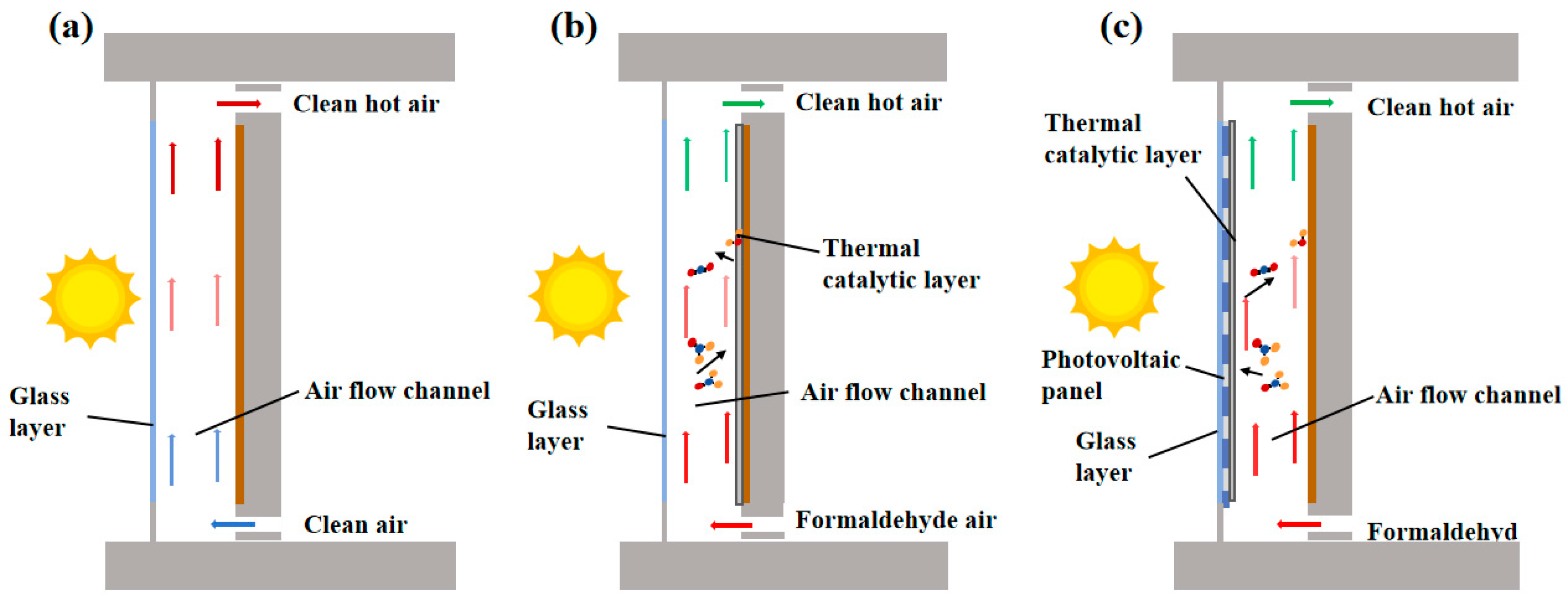
2. The Description of Three Different Types of Trombe Walls
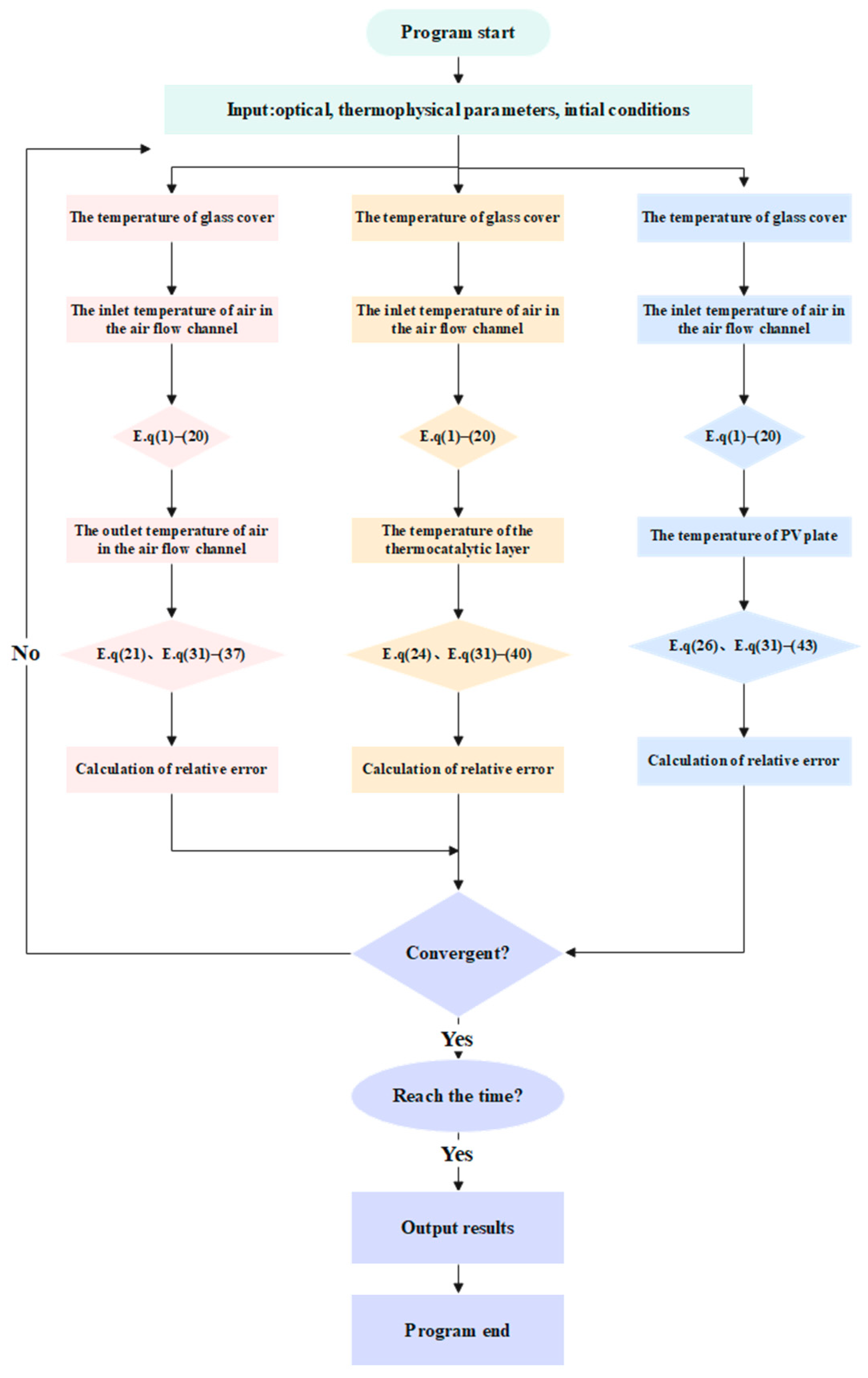
The traditional Trombe wall (Figure 1a) design comprises glass, an air channel, a heat-absorbing plate, and a thermally massive wall [28]. The TC Trombe wall (Figure 1b) represents an advanced modification of the conventional Type I Trombe wall system, incorporating a thermally catalytic layer composed of α-MnO2 nanoparticles deposited on the surface of the heat-absorbing plate. This innovative enhancement significantly improves the system’s thermal performance through catalytic surface reactions and optimized heat transfer characteristics. Under solar irradiation, the thermal catalytic layer heats the Trombe wall’s airflow channel to 60–100 K [29], thereby providing space heating with clean and warm air flowing into the room. The TC-PV Trombe wall (Figure 1c) enhances this system by integrating a photovoltaic panel behind the glass and catalytic material on its back, combining power generation, heat collection, and air purification into a single multifunctional unit. The versatility of this system greatly improves the overall energy efficiency and provides strong technical support for green buildings.

3. Energy Analysis

To make an energy conservation analysis of the Trombe wall, we first make the following assumptions:
(1)
The system operates under steady-state conditions, assuming the air behaves as an ideal gas and the thermophysical parameters within the system remain constant;
(2)
Given the high thermal insulation of the sidewall, heat loss is considered negligible [30];
(3)
Given the tightly bonded nature of the glass and the photovoltaic panel, heat transfer due to irradiation intensity between them is neglected;
(4)
Given the thinness of the glass and its low heat transfer coefficient, the glass is treated as a single node and heat transfer in both the thickness and height directions is neglected.
For Type I Trombe walls, the energy conservation equation is as follows:
Extensive literature review and validation studies indicate that the thermal transport phenomena occurring through the glass plate can be effectively modeled using one-dimensional heat transfer assumptions. This widely accepted approach, consistently demonstrated in multiple research investigations, offers a practical balance between computational efficiency and model accuracy for system analysis purposes.
m g l c g l d T g d t = α g l I + h o u t T a m b T g l + h s g T s k y T g l + h a g T a i r T g l + h x g T x T g l
The heat transfer coefficients are defined as follows: hout (W/m2·K) for environment-to-glass convection (gl, glass cover), hsg (W/m2·K) for sky-to-glass radiation, hag (W/m2·K) for air-to-glass radiation in the airflow channel, and hxg (W/m2·K) for absorber-to-glass radiation. The glass properties include the absorption coefficient (αgl). The temperature parameters comprise the glass plate (Tgl, K), ambient (Tamb, K), sky (Tsky, K), airflow channel air (Tair, K), and heat absorbing plate (Tx, K). The system receives solar irradiation with intensity I (W/m2).
Based on fundamental heat transfer principles and experimental validation, the convective heat transfer coefficient governing the thermal exchange between the glass plate surface and ambient air can be calculated through the following relationship [31], with the parameter uamb (m/s) corresponding to the measured ambient wind speed. This equation has been widely adopted in the thermal analysis of building envelope systems.
h o u t = 6.5 + 3.3 u a m b
The following formula can be used to calculate the sky temperature [32]:
T s k y = 0.0552 T a m b 1.5
The sky-to-glass radiative heat transfer coefficient can be determined through the following equation [33]:
h s g = ε g l σ T s k y 2 + T g l 2 T s k y + T g l
where εgl is the emissivity of glass and σ is the Boltzmann constant.
To calculate the heat transfer coefficient between the heat-absorbing plate and the glass plate, the following formula can be used [34]:
h x g = σ T x 2 + T g l 2 T x + T g l 1 1 / ε g l + 1 / ε x
where εx is the emissivity of the absorber plate.
N u = 0.68 + 0.670 R a 1 / 4 [ 1 + ( 0.492 / P r ) 9 / 16 ] 4 / 9   Ra < 10 9 N u = 0.825 + 0.387 R a 1 / 4 [ 1 + ( 0.492 / P r ) 9 / 16 ] 8 / 27   Ra < 10 9
h a g = N u λ a ir δ a i r
where λair (W/m·K) denotes the air thermal conductivity in the channel. The Prandtl number (Pr), a key dimensionless group in convective heat transfer, quantifies the ratio of viscous to thermal diffusion rates, governing the thermal boundary layer development in fluid systems [35].
The energy conservation equation of air in the air flow channel is
ρ a i r δ a i r c a i r d T a i r d t = h a w T w T a i r + h a g T g l T a i r ρ a i r δ a i r c a i r V a i r d T a i r d y
where ρair (kg/m3), δair (m), and cair (J/kg·K) represent the air density, characteristic thickness, and specific heat capacity, respectively, defining the fundamental thermophysical properties of the air channel.
h a w = N u λ a i r δ a i r
Under natural convection conditions, the air velocity in the airflow channel can be determined using the following calculation formula:
V a i r = 1 2 g β T o u t T i n H C i n A / A i n 2 + C o u t A / A o u t 2 + f H / d e 2
The system parameters include Cin and Cout as the local resistance coefficients at the channel inlet and outlet, respectively, and f as the airflow channel’s friction coefficient. Temperature measurements comprise the channel’s air inlet (Tin, K) and outlet (Tout, K) temperatures. Geometric parameters include the Trombe wall’s flow channel cross-sectional area (A, m2), inlet area (Ain, m2), and outlet area (Aout, m2), along with the channel height (H, m) and hydraulic diameter (de, m). Physical constants consist of gravitational acceleration (g, m/s2) and air’s thermal expansion coefficient (β, 1/K).
The calculation method of f is as follows:
f = 0.3164 R e 0.25
where Re is the Reynolds number.
When the flow is laminar, the formula for calculating the friction coefficient of the flow channel is f = 16 / R e .
When the flow is turbulent, the Blasius equation is used to describe frictional resistance: f = 0.3164 R e 0.25 .
The Type II Trombe wall maintains similar heat transfer mechanisms to Type I, with the catalytic layer replacing the heat-absorbing plate in the thermal process. During energy conservation analysis, the focus shifts from detailed glass plate examination to a comprehensive analysis of the catalytic layer’s heat transfer and air channel purification processes. The thermal transport mechanism within the catalytic layer can be effectively characterized using a one-dimensional steady-state heat transfer model. The governing equation for this thermal process is expressed as follows:
c c t ρ c t W c t δ c t d T c t d t = λ c t δ c t d 2 T c t d y 2 + κ g α c t W c t G + h a c W c t T a i r T c t + h c g W c t T g l T c t + h w c W c t T w T c t
The catalytic layer properties include density (ρct, kg/m3), specific heat capacity (cct, J/kg·K), width (Wct, m), thickness (δct, m), thermal conductivity (λct, W/m·K), and absorptivity (αct). Heat transfer coefficients comprise air-to-catalytic layer convection (hac, W/m2·K), catalytic layer-to-glass radiation (hcg, W/m2·K), and wall-to-catalytic layer conduction (hwc, W/m2·K). The glass emissivity is denoted as κg.
The Trombe wall system incorporating a purification mechanism involves dual processes within the airflow channel: heat transfer and air purification. The coupled heat and mass transfer model governing these processes is structured as follows:
ρ a i r δ a i r c a i r d T a i r d t = h a c T c t T a i r + h a g T g l T a i r ρ a i r δ a i r c a i r V a i r d T a i r d y
L a i r d C H C H O d t + V a i r L a i r d C H C H O d y + h m C H C H O C s = 0
The formaldehyde concentrations are defined as CHCHO (ppb) in the airflow channel and Cs (ppb) at the catalyst layer surface. Additional parameters include the convective mass transfer coefficient (hm, W/m2·K) and the airflow channel height (Lair, m).
The calculation method of Cs [36] can be referred to:
C s = C H C H O 1 + ω H C H O h m C s
The calculation method of ωHCHO [37] is
ω H C H O = h m C H C H O C s
where ωHCHO (ppb m/s) represents the rate of the thermal catalytic reaction for formaldehyde.
In Type III Trombe wall systems, the intricate details of heat transfer and purification processes within the airflow channel are not explicitly incorporated into the model. Instead, the system is characterized by a streamlined energy conservation equation [31] formulated as follows:
ρ g l c g l δ g l d T g l d t = λ g l δ g l d 2 T g l d x 2 + h o u t ( T a m b T g l ) + h s g ( T s k y T g l ) + h a g ( T a i r T g l ) + h p g ( T p v T g l ) + α g I
The system parameters include the PV plate temperature (Tpv, K) and the PV-to-glass radiative heat transfer coefficient (hpg, W/m2·K).
ρ w a l l c w a l l d T w a l l d t = λ w a l l d 2 T w a l l d x 2
where cwall (J/kg·K) is the specific heat capacity of the wall; λwall (W/m·K) is the thermal con-ductility.
The radiative heat transfer coefficient between the PV plate and the glass is expressed by the following Formula (19) [34].
h p g = σ ( T g l 2 + T p v 2 ) ( T g l + T p v ) ξ 1 / ε P V + ξ ( 1 / ε c t 1 ) + 1 ξ 1 / ε pv + ( 1 ξ ) ( 1 / ε c t 1 )
where ξ is considered as the filling factor, and its expression is
ξ = A P V / A g l
where Apv (m2) and Agl (m2) are the area of PV plate and the glass area of Trombe wall.
The following section presents a comprehensive assessment of system performance through three distinct efficiency metrics: thermal efficiency, purification efficiency, and electrical efficiency. Grounded in the first law of thermodynamics, energy efficiency is mathematically expressed as the percentage of utilizable energy output relative to total energy input. The thermal performance of the Trombe wall is determined by the following governing equation [38]:
η t o t a l , I = Q IA g l
Here, Q represents the total heat gained by the air from solar energy in the airflow channel. The calculation method is as follows:
Q = ρ a i r c a i r q a i r ( T o u t T i n )
Here, qair (m3/s) denotes the volume flow rate of air in the airflow channel.
The primary degradation efficiency of formaldehyde can be obtained by the following formula [36].
θ = C i n C o u t C i n
While formaldehyde degradation efficiency and thermal efficiency serve as performance metrics for Trombe walls, they represent fundamentally distinct evaluation perspectives. This dichotomy poses significant challenges in developing a unified framework for comprehensive performance assessment. Consequently, conventional energy analysis proves inadequate for evaluating Type II Trombe walls with purification functionality, as it fails to account for the energy significance of the purification process.
η t o t a l , II = η t o t a l , I
For the type II Trombe wall with catalytic function, we cannot unify it from an energy point of view.
Type III Trombe walls should not only consider the thermal efficiency and formaldehyde purification efficiency but also consider the performance benefits brought by photovoltaic power generation. The calculation formula of electrical efficiency is as follows:
η p v = η r [ 1 0.005 ( T p v 26 ) + 0.085 ln ( I / 1000 ) ]
The reference efficiency of the PV plate at 299 K is defined as ηr = 0.2. Based on the photoelectric effect principle, the comprehensive efficiency of a Type III Trombe wall can be expressed as ηtotal,III [39].
η t o t a l , III = η t o t a l , I + η p v
From Equations (21), (24) and (26), we can see that energy analysis cannot view the energy utilization of the Trombe wall from the same perspective. The indispensable part of energy has not been properly reflected. Therefore, we believe that energy analysis cannot comprehensively view the Trombe wall.

4. Exergy Analysis

Exergy analysis has emerged as a novel methodology in energy system evaluation, providing a comprehensive assessment of energy utilization efficiency. This section applies exergy analysis to evaluate the performance of multifunctional Trombe walls, specifically focusing on their integrated purification, power generation, and heat collection capabilities.
The system’s exergy efficiency is defined as the ratio of useful exergy output to total exergy input.
φ t o t a l = E x i n c o m e E x d i s b u r s e
The thermal exergy efficiency is defined as the ratio of the thermal exergy obtained by the Trombe wall to the thermal exergy of the solar input.
φ = E x t h E x s u n
The definition of chemical exergy is based on the purification function of the Trombe wall and the chemical energy obtained in the chemical process after the catalytic reaction is generated. The chemical exergy efficiency is defined as the ratio of the chemical exergy obtained by Trombe due to purification and the heat exergy of the solar input.
φ = E x chemical E x sun
The electric exergy is defined as the electric energy obtained by the Trombe wall photovoltaic power generation and the electric exergy efficiency is defined as the ratio of the electric exergy output by the Trombe wall to the heat exergy input by the sun.
φ = E x electricity E x sun
The thermodynamic properties, including mass and energy parameters, are quantitatively analyzed using Aspen Plus simulation software V12. For a standard steady-state operational condition, the fundamental mass and energy balance equations can be mathematically expressed as follows:
i n m i n = o u t m o u t
When kinetic and potential exergy components are neglected, the total exergy of a system consists of both physical and chemical exergy components. The physical exergy can be calculated using the established methodology described in reference [40]:
  E x = m [ ( h 1 h 0 ) T 0 ( s 1 s 0 ) ]
The formula incorporates the following thermodynamic parameters: h1 and h0 represent the specific enthalpy values at the current state and reference state, respectively, while s1 and s0 denote the specific entropy values at the corresponding states. The reference temperature T0 is defined as 298.15 K (25 °C) in this calculation.
The energy conservation equation is as follows:
Q s u n = Q t h + P p v + E c h e m i c a l + Q l o s s
In the formula, Qsun is the heat energy absorbed by the Trombe wall from the sun, Qth is the heat energy obtained by the air, Ppv is the electric energy produced by Trombe, Echemical is the chemical energy required by Trombe due to the purification process, and Qloss is the heat energy loss of the system.
The exergy balance equation of the Trombe wall is shown by Equation (34) [41]:
E x s u n = E x t h + E x c h e m i c a l + E x d e s t + E x p v
where Exsun is the heat exergy obtained from solar irradiation intensity. The calculation formula of Exsun [42] is as follows:
E x s u n = 1 4 T a m b 3 T s u n I A
Tsun (K) is the temperature of the sun. Considering the effective temperature of the sun, we think that the temperature of the sun as an energy source is 4500 K [43]. For the traditional Trombe wall, only solar energy is used to heat the air in the air flow channel. There is no chemical reaction process in the air flow channel, so only the part of the exergy that heats the air becomes heat.
The calculation formula of heat exergy is
E x t h = E x o u t a i r E x i n a i r = = ρ f V a i r [ c p ( T o u t T i n ) T a m b ( c v L n T o u t T i n R ln ρ o u t ρ i n ) ]
The thermodynamic properties include ρf (kg/m3), representing the air density; cp (J·kg−1·K−1), denoting the specific heat capacity at constant pressure; cv (J·kg−1·K−1), indicating the specific heat capacity at constant volume; ρin (kg/m3), representing the inlet air density; and ρout (kg/m3), corresponding to the outlet air density.
The Type I wall demonstrates an exergy efficiency [44], representing the ratio of useful energy output to the total exergy input in the system.
φ I = t 1 t 2 E x th d t t 1 t 2 E x sun d t
The redox reaction occurs in the catalytic layer of the Type II Trombe wall, as shown in Formula (38). The purification exergy is the maximum useful work generated by the chemical reaction in the standard state.
H C H O + O 2 C O 2 + H 2 O
The calculation method of purification exergy [45] is
E x p u r = E x c h e m i c a l = x i E i 0 + R T 0 x i ln x i
where xi is the mass fraction of a species in the gas mixture, E i 0 is the standard purification exergy of the substance, and the standard chemical energy is defined as the purification energy and pressure P0 of any energy reference environment of the ambient temperature T standard value, such as 298.15 K and 1 atm [41]. R is the general gas constant.
Compared with the traditional Trombe wall, the TC-Trombe wall can use heat to drive the thermal catalytic layer for formaldehyde purification. This part of the heat used for chemical reactions is available energy, which is reflected in the form of purification exergy. The exergy efficiency of the Type II wall is
φ II = t 1 t 2 ( A gl E x th + E x chemical ) d t A gl t 1 t 2 E x sun d t
The TC-PV Trombe wall greatly improves its exergy efficiency through the photovoltaic effect. The principle of the electro-exergy calculation method is that electrical energy can be 100% converted into available energy. We believe that the generated electrical energy is the electric exergy.
E x p v = E p v
The electrical efficiency of the TC-PV Trombe wall can also be expressed as [46]
η pv = A pv t 1 t 2 E pv d t A gl t 1 t 2 Ex sun d t = A pv t 1 t 2 Ex pv d t A gl t 1 t 2 E sun d t
The exergy efficiency of the TC-PV Trombe wall is [39]
φ III = t 1 t 2 ( A g l E x t h + E x c h e m i c a l + A p v E x p v ) d t A g t 1 t 2 E x s u n d t = t 1 t 2 ( A g l E x t h + E x c h e m i c a l ) d t A g t 1 t 2 E x s u n d t + ξ η p v
Through the systematic analysis based on Equations (21), (24), (37), (40) and (43), we have conducted a comprehensive evaluation of various Trombe wall configurations, examining both quantitative energy performance and qualitative energy characteristics. This analytical approach has enabled the establishment of a clear correlation between energy efficiency and exergy efficiency metrics.
The exergy analysis of Trombe walls requires comprehensive consideration of two primary aspects: internal irreversible processes and external energy interactions. Internally, thermodynamic irreversibilities, including viscous friction and finite temperature difference heat transfer, must be accounted for. Externally, the energy exchange mechanisms between the system and its surrounding environment should be thoroughly evaluated. Through quantitative assessment of these exergy loss components, a more precise evaluation of the system’s energy conversion efficiency and thermodynamic characteristics can be achieved, ultimately leading to optimized thermal performance.
This paper takes the exergy loss calculation of the TC-Trombe wall as an example.
The loss can be calculated according to the following formula [30]:
E x d e s t = E x d e s t 1 + E x d e s t 2 + E x d e s t 3 + E x d e s t 4 + E x d e s t , else
Exdest1 is the loss of exergy caused by thermal radiation caused by glass emission and thermal convection with external air:
E x d e s t 1 = ε gl σ A g l ( T g l 4 T amb 4 ) ( 1 T amb T g l ) + h out A g l ( T g l T amb ) ( 1 T amb T g l ) + I A g l α g l ( T amb T g l T amb T s u n )
Exdest2 is the exergy loss caused by air thermal convection in the air flow channel:
E x d e s t 2 = T amb [ ρ air V air c p l n T o u t T i n Q 1 T g l Q 2 T ct ]
Q 1 = h a g A g l ( T gl T air )
Q 2 = h ac A ct ( T ct T air )
Exdest3 is the exergy loss due to radiation between the glass and the thermocatalytic layer:
E x d e s t 3 = σ A c t ( T c t 4 T g l 4   ) 1 ε c t + 1 ε g l 1   ( T a m b T g l T a m b T c t )
In the formula, εct is the emissivity of the thermal catalytic layer.
Exdest4 is the exergy loss caused by the heat absorption of the thermocatalytic layer:
E x d e s t 4 = I A c t τ g l α c t ( T a m b T c t T a m b T s u n ) E x c h e m i c a l
The Tair calculation method [47] is
T a i r = γ T o u t + ( 1 γ ) T i n
In the formula, γ is 0.74.
In the actual process, there are complex irreversible processes that cause losses. We use Exdest,else to represent these losses, and we think
E x d e s t , else = E x s u n E x t h ( E x d e s t 1 + E x d e s t 2 + E x d e s t 3 + E x d e s t 4 )
The model of the system is solved by MATLAB2023b software and analyzed by test data. We use MATLAB to solve the coupled heat/mass transfer equation and use the finite volume method for discretization (The specific parameters and calculation process are shown in Table 1 and Figure 2).

5. Results and Discussion

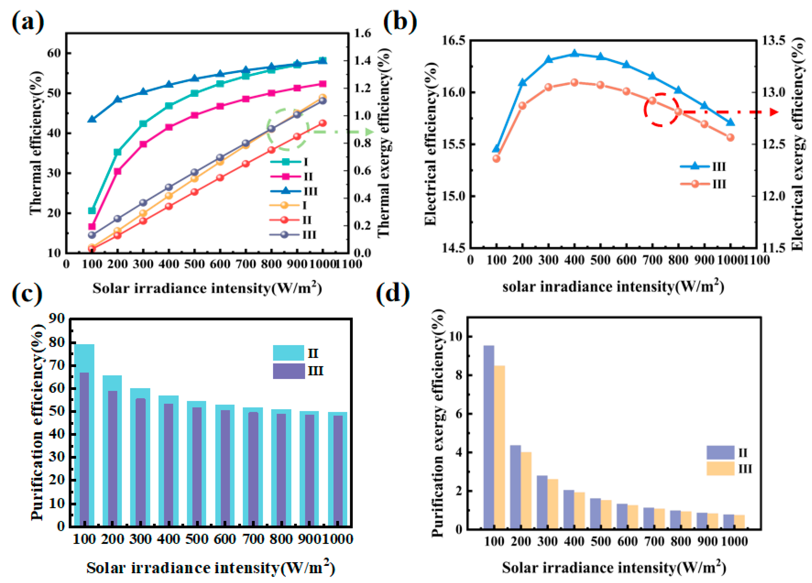
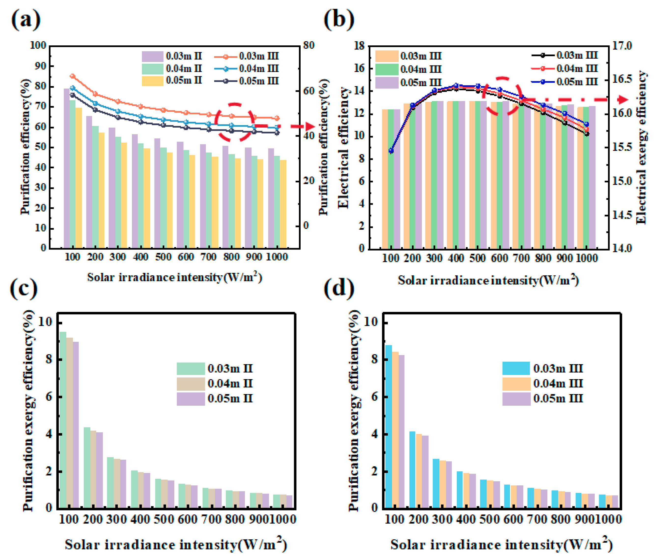
5.1. The Effect of Solar Irradiation Intensity

The comparative thermal exergy performance of the three Trombe wall variants across varying solar intensities is presented in Figure 3a, with experimental data analyzed with existing literature for comprehensive performance evaluation.
Analysis of the performance data demonstrates a clear positive relationship between solar irradiation intensity and thermal efficiency in all Trombe wall variants, with efficiency values stabilizing at higher irradiation levels. The Type III system emerges as the most thermally efficient configuration, owing to its innovative integration of photovoltaic technology. This design achieves dual benefits: enhanced solar energy capture and improved thermal transport in the airflow channel. The system’s thermal dynamics are particularly efficient, with air temperature increases surpassing the rate of solar intensity growth, resulting in significantly amplified thermal efficiency improvements compared to conventional designs.
Comparative analysis reveals distinct thermal performance characteristics between the two Trombe wall configurations. While the Type II system demonstrates superior solar absorption capacity due to its enhanced surface properties, the Type I Trombe wall achieves higher overall thermal efficiency. This apparent paradox can be attributed to the fundamental difference in heat transfer mechanisms: the Type I system’s heat-absorbing plate exhibits more effective solar-to-thermal energy conversion compared to the thermal catalytic material employed in Type II. Consequently, the Type I configuration facilitates more efficient heat transfer from solar radiation to the airflow channel, resulting in superior air heating performance.
These findings are consistent with the literature, which suggests that the design and material composition of Trombe walls significantly impact their thermal performance under varying solar conditions. The results underscore the importance of optimizing the integration of photovoltaic elements and heat-absorbing materials to enhance the overall efficiency of Trombe walls.
In a similar vein, Figure 3b presented the trends of electrical efficiency and electrical exergy efficiency of the Type III Trombe wall as a function of solar irradiation intensity. Both electrical efficiency and electrical exergy efficiency initially increased with solar irradiation but eventually decreased after reaching a peak at around 400 W/m2. This pattern reflected the influence of temperature on photovoltaic module performance. At moderate solar irradiation levels, the efficiency of the photovoltaic panels improved as they absorbed more energy. However, as the intensity continued to rise, the increased temperature caused the photovoltaic panels to heat up, leading to a decrease in conversion efficiency. The drop in efficiency at high solar irradiation intensity could be attributed to the inherent temperature sensitivity of photovoltaic cells. Excessive heat caused increased resistance and lowered the voltage output of the modules, thereby reducing their overall electrical efficiency. This suggested that while solar irradiation intensity played a crucial role in driving both thermal and electrical energy generation in the Trombe wall system, excessive heat may have hindered the performance of the system beyond a certain threshold. This trade-off between energy absorption and temperature effects underscored the need for an optimal balance between solar irradiation and temperature management to maximize the performance of integrated Trombe wall systems (Figure 3b).
Figure 3c,d demonstrate an inverse relationship between solar irradiation intensity and formaldehyde degradation efficiency in Type II and Type III Trombe walls, accompanied by corresponding changes in purification exergy efficiency. This phenomenon can be explained by two interrelated thermal–fluid dynamic effects: (1) Elevated air temperatures reduce formaldehyde adsorption on catalytic surfaces and (2) increased airflow rates decrease reactant residence time. These combined effects lead to fewer formaldehyde molecules interacting with catalytic sites, thereby diminishing both degradation efficiency and purification exergy performance.
The decreased formaldehyde degradation efficiency means that the redox reaction involving formaldehyde (HCHO) was less effective, leading to a reduced conversion rate of HCHO into CO2 and H2O. This, in turn, lowered the purification exergy of the system. Similar findings have been reported in studies involving the photocatalytic degradation of formaldehyde, where excessive heat can interfere with the adsorption and reaction of pollutants on the catalytic surface [48]. The observed decrease in both efficiencies highlights the complexity of the catalytic process concerning solar irradiation intensity, suggesting that excessive heat could interfere with the adsorption and reaction of pollutants on the catalytic surface, ultimately reducing the overall performance of the system. This aligns with previous research indicating that while solar irradiation enhances the photocatalytic activity, there is an optimal range beyond which the efficiency may decline due to the thermal deactivation of the catalyst.

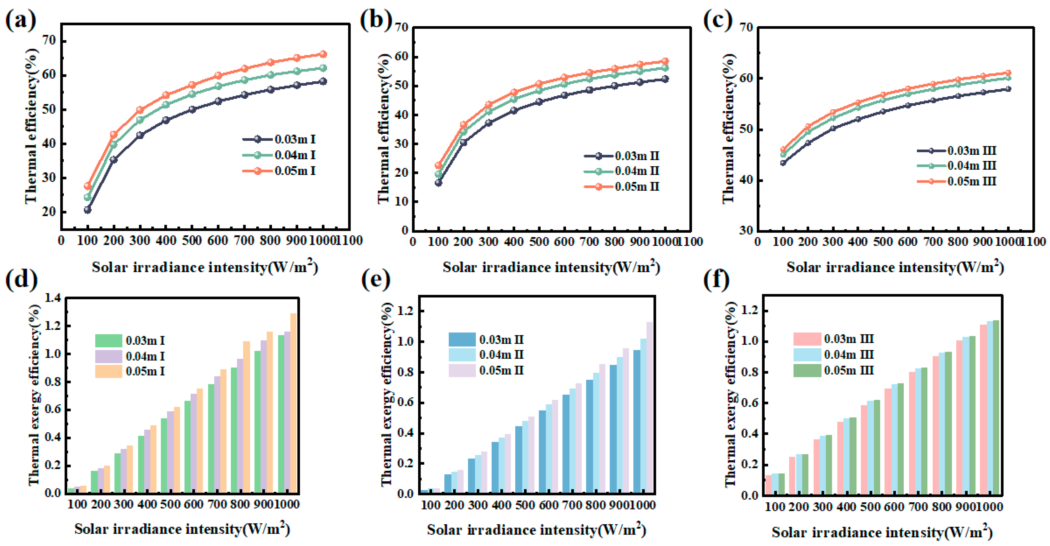
5.2. The Effect of Air Channel Depth

Figure 4a–c presents the thermal performance characteristics of the three Trombe wall configurations as a function of airflow channel thickness, investigated at 0.03 m, 0.04 m, and 0.05 m intervals. The experimental data reveal a positive correlation between channel thickness and thermal efficiency across all systems, with progressively improved heat transfer performance observed as the channel dimension increases. This trend is consistent with the findings of Minoo Askari et al. [49], who studied the thermal performance of a dual phase change material modified Trombe wall and observed that increasing the air flow channel thickness led to better comprehensive thermal performance. This improvement can be attributed to a change in the dominant heat transfer mechanism within the air flow channel. At smaller air flow channel thicknesses (0.03 m), heat transfer was primarily governed by conduction, which is less efficient compared to convection. However, as the channel thickness increased, heat transfer transitioned from conduction to convection. Convective heat transfer, being more efficient, facilitated better energy exchange between the air and surrounding surfaces. This resulted in a more effective heat collection process, thereby increasing the thermal efficiency of the system. This trend emphasizes the importance of optimizing air flow channel thickness to enhance convective heat transfer and improve the overall performance of Trombe wall systems.
Figure 5a illustrates the relationship between formaldehyde degradation efficiency and air channel thickness for Type II and Type III Trombe walls. The experimental data reveal an inverse correlation between channel thickness and degradation efficiency, primarily attributed to reduced airflow velocity in wider channels. This velocity reduction decreases both heat and mass transfer coefficients, limiting the number of formaldehyde molecules reaching the catalytic surface and consequently reducing catalytic activity. Furthermore, the decreased airflow promotes air stagnation within the channel, increasing the formaldehyde concentration that requires treatment while simultaneously reducing the system’s catalytic capacity, ultimately leading to diminished overall degradation performance.
This highlights the importance of optimizing the air flow channel thickness to enhance the effectiveness of formaldehyde degradation in Trombe wall systems.
Figure 5b presents the electrical efficiency characteristics of the Type III Trombe wall as a function of airflow channel thickness. The experimental data demonstrate a positive correlation between channel dimension and electrical performance, primarily attributed to enhanced thermal management. The increased channel volume facilitates greater airflow, which effectively removes heat from the photovoltaic surface through convective cooling, thereby improving the PV cells’ operating conditions and overall electrical conversion efficiency.
Our previous research [31] found that too high a temperature will reduce the electrical efficiency of the photovoltaic cell, and the electrical efficiency of the photovoltaic cell can be effectively improved by reducing the photovoltaic module through air, water, refrigerant, or nanofluids.
Similarly, the trends in thermal exergy efficiency, purification exergy efficiency, and electrical exergy efficiency for the three Trombe walls, with varying air flow channel thicknesses, are presented in Figure 4d–f and Figure 5b–d. These trends followed the same pattern as the energy efficiency changes. According to the concept of exergy, a higher energy efficiency implies that more usable energy is available for work, leading to a higher exergy efficiency. Therefore, as the air flow channel thickness increased and the system’s energy efficiency improved, the corresponding exergy efficiencies—whether thermal, purification, or electrical—also showed an upward trend. This finding underscores the significant performance enhancement achieved through airflow channel optimization in Trombe wall systems, demonstrating simultaneous improvements in both energy conversion efficiency and exergy utilization across all system components. The optimized channel geometry effectively balances thermal and electrical performance, maximizing overall system functionality.

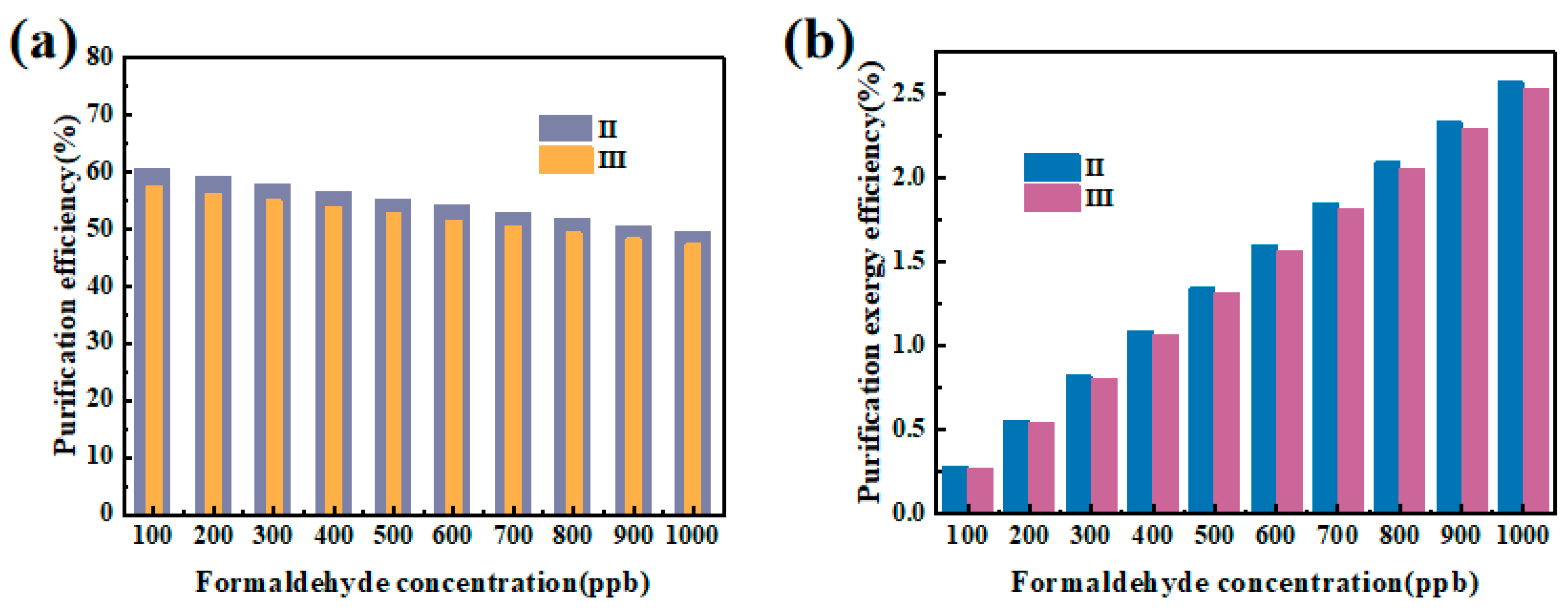
5.3. The Effect of Formaldehyde Concentration

When analyzing the effect of formaldehyde concentration on the performance of the Trombe wall, we focused primarily on the formaldehyde degradation efficiency and purification exergy efficiency while not considering the thermal and electrical effects. This is because changes in formaldehyde concentration do not significantly influence the thermal and electrical performance of the system. Therefore, the impact of formaldehyde concentration on the Trombe wall’s thermal and electrical effects was not analyzed in this study.
The formaldehyde degradation efficiency of the Type II and Type III Trombe walls gradually decreased as the formaldehyde concentration increased (Figure 6a). For a certain amount of catalyst at a certain reaction temperature, the amount of formaldehyde that needs to be degraded increases with the increase of formaldehyde concentration, but the reaction ability of the catalyst is limited by the catalyst quality and reaction temperature, resulting in a decrease in the apparent catalytic efficiency.
A noteworthy phenomenon is that although the catalytic purification efficiency decreases with the increase of formaldehyde concentration (Figure 6a), the purification exergy efficiency increases with the increase of formaldehyde concentration, as shown in Figure 6b. This is due to the increasing formaldehyde concentration, which caused a higher rate of purification exergy generation during the degradation process. The higher the concentration of formaldehyde, the higher the purification energy generated by the unit pollutant. Consequently, the overall purification exergy efficiency increased despite the reduction in degradation efficiency. This indicates that, at higher pollutant concentrations, the exergy generated by the chemical reactions could offset the decrease in efficiency, leading to an increase in purification exergy efficiency.

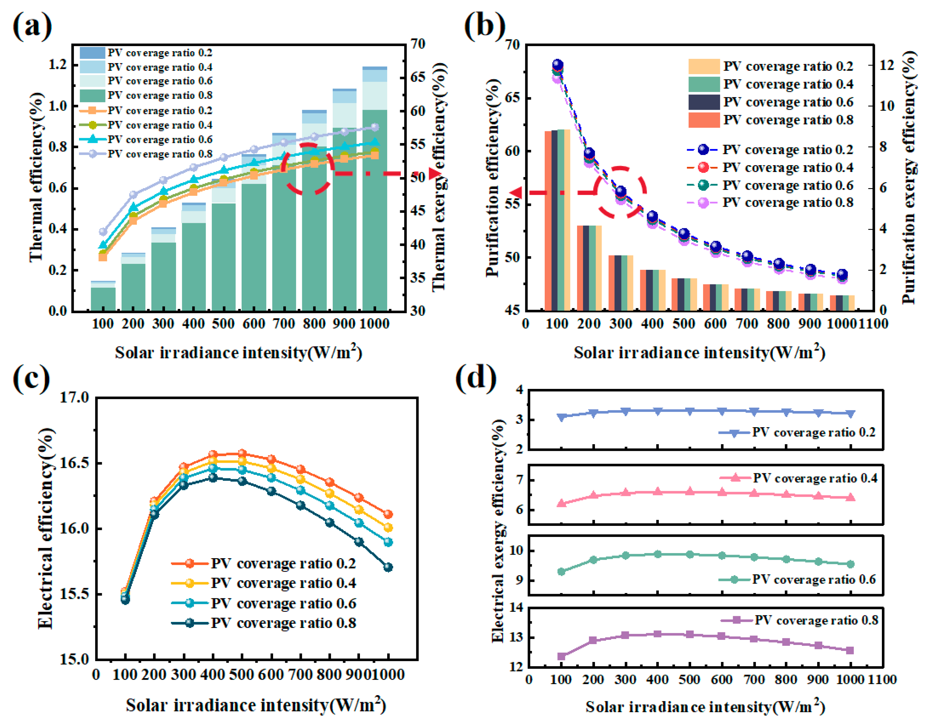
5.4. The Effect of Rate of PV Coverage

Figure 7a demonstrates a positive correlation between photovoltaic coverage ratio and system performance in the Type III Trombe wall, with both thermal efficiency and thermal exergy efficiency showing significant improvement. The expanded photovoltaic surface area facilitates greater solar energy utilization, simultaneously improving thermal performance and exergy recovery through optimized energy conversion processes.
On the other hand, the formaldehyde degradation efficiency and purification exergy efficiency demonstrated a downward trend with the increase in photovoltaic cell coverage, as shown in Figure 7b. This is consistent with our previous research results. With the expansion of photovoltaic cell coverage, the system heat collection is enhanced, increasing air temperature and air flow rate, which in turn leads to a decrease in the adsorption of formaldehyde molecules on the catalytic surface, and ultimately a decrease in the overall formaldehyde degradation efficiency. This, in turn, leads to a reduction in the purification exergy produced by the catalytic reaction, resulting in a decrease in purification exergy efficiency. While the higher photovoltaic coverage improves the thermal performance of the Trombe wall, it also negatively affects the air purification performance, particularly concerning formaldehyde degradation. This trade-off highlights the complex balance between energy collection, heat transfer, and purification efficiency in the integrated system.
The electrical efficiency of the Type III Trombe wall decreased as the photovoltaic cell coverage increased (Figure 7c). This behavior can be attributed to a combination of factors. As the coverage area of the photovoltaic cells grew, the current generated by the cells increased, but the voltage did not scale proportionally. This imbalance between current and voltage led to a diminished output power due to internal resistance, which in turn caused a reduction in the overall electrical efficiency. Additionally, the expansion of the photovoltaic cell area caused a rise in the temperature of the catalytic layer. Higher temperatures typically harm photovoltaic efficiency, as elevated temperatures can reduce the voltage output of the photovoltaic panels. Therefore, while the larger area of photovoltaic cells captured more solar energy, the associated temperature increases and mismatch between current and voltage expansion contributed to the observed decrease in electrical efficiency.
It is worth noting that although the electrical efficiency of the system decreases with the increase of photovoltaic cell coverage, the electrical exergy efficiency of the system increases, as shown in Figure 7d. This is mainly because the power generation of photovoltaic cells is proportional to their surface area. The larger the system coverage ratio, the more solar radiation intensity absorbed and the greater the total power output. The larger photovoltaic area effectively enhances the overall power generation, thus improving the electrical exergy efficiency. Therefore, although the increase of photovoltaic coverage will reduce the electrical efficiency of photovoltaic cells per unit area to a certain extent, it will significantly increase the electrical exergy efficiency of the system, making a larger photovoltaic coverage rate show a better system energy-saving advantage.

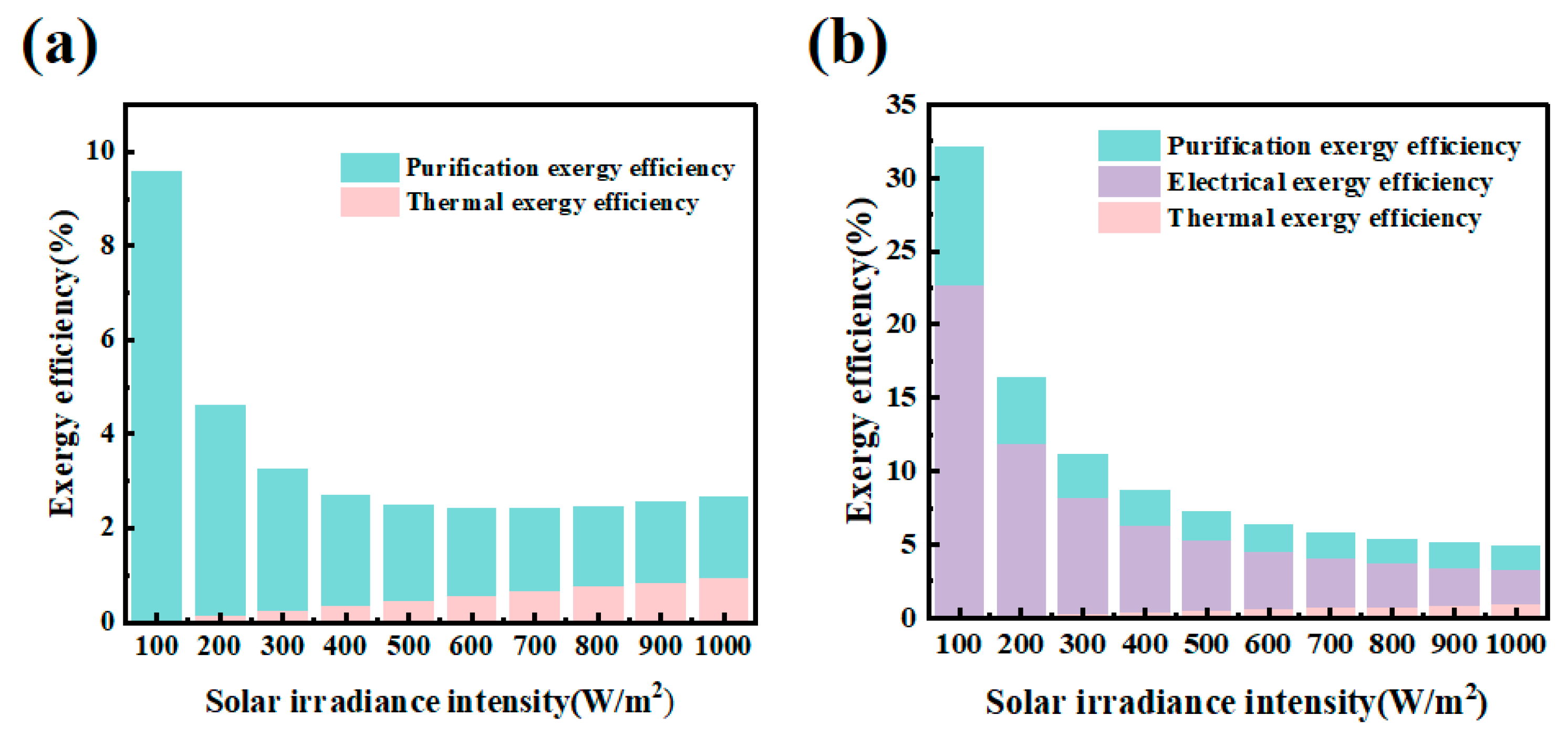
5.5. Gain and Loss of Exergy

The integration of air purification functionality in both TC Trombe wall and TC-PV Trombe wall systems significantly enhanced their energetic performance through additional exergy gains from pollutant degradation. However, thermodynamic analysis based on the second law reveals inherent irreversibilities in these systems, manifested through various transfer resistances and reaction limitations, as illustrated in Figure 8. To optimize system performance, a detailed exergy analysis identifying and quantifying individual component losses is essential for targeted efficiency improvements.
All kinds of temperature difference heat transfer processes and air flow processes in the Trombe wall produced entropy and caused exergy loss.
As detailed in Table 2 and Table 3, the exergy destruction components (Exdest1–4 and Exelse) correspond to Equations (44), (45), (48), (49) and (51), respectively. The data reveal that Exdest4 represents the predominant energy loss mechanism in both TC and TC-PV Trombe walls, accounting for 70% and 73% of total losses, respectively. While all three Trombe wall configurations demonstrate high thermal efficiency, their thermal exergy efficiency remains relatively low due to two fundamental factors: (1) the inherent low-grade nature of thermal energy and (2) significant heat transfer losses throughout the system. The majority of the absorbed solar energy is dissipated through photovoltaic and heat-absorbing panels, with only a minor fraction effectively utilized for air heating, electricity generation, and purification processes. To address these limitations, several optimization strategies are proposed: (1) Implementation of advanced materials with superior thermal properties, (2) enhancement of wall insulation characteristics, (3) geometric optimization of wall design, and (4) improvement of structural sealing integrity. These measures collectively aim to minimize energy losses and maximize solar energy utilization efficiency in Trombe wall systems.
Cao et al. [50] conducted energy analysis and exergy analysis on the photocatalytic Trombe wall purified by visible light photocatalysis. The results showed that the catalytic layer caused the greatest energy damage during the operation of the system. By increasing the absorption rate of the catalyst, increasing the width of the air duct, and adjusting the area of the inlet and outlet air, the energy efficiency of the system can be improved, which is consistent with our research results. The thickening section in Table 3 highlights the important loss section.
We have systematically compared and analyzed the results of this research with the existing literature, as shown in Table 4:

6. Conclusions

A comprehensive performance evaluation of any novel Trombe wall system necessitates a detailed analysis of its multifunctional energy efficiency characteristics. This study introduces an integrated energy–exergy analysis methodology to assess and compare the thermal, purification, and electrical performance of three Trombe wall configurations: traditional, TC Trombe, and TC-PV Trombe walls. The proposed evaluation framework enables systematic optimization of both design and operational parameters, including the solar irradiance intensity, airflow channel dimensions, formaldehyde concentration levels, and photovoltaic coverage ratio. These analyses provide essential insights for the development of optimized composite wall systems with enhanced multifunctional performance.
(1)
The energy efficiencies of three Trombe systems were analyzed. The thermal efficiency of a conventional Trombe wall is 47.2%. The thermal efficiency of a TC Trombe wall is 41.9% and the purification efficiency is 57.0%. The thermal efficiency, purification efficiency, and electrical efficiency of a TC-PV Trombe wall are 51.7%, 53.0%, and 16.0%, respectively.
(2)
The exergy efficiencies of three Trombe systems were analyzed. The traditional Trombe wall has a thermal exergy efficiency of 0.59%. The TC Trombe wall has thermal and purification exergy efficiencies of 0.49% and 2.53%, respectively. The TC-PV Trombe wall has thermal, purification, and electric exergy efficiencies of 0.63%, 2.42%, and 12.84%, respectively. Purification exergy boosts the efficiency of the TC and TC-PV Trombe walls by 3.6 and 0.24 times, respectively.
(3)
Higher solar irradiation and wider air channels boost thermal exergy efficiency but lower purification exergy efficiency. Electrical exergy efficiency peaks at 400 W/m2 solar irradiation and 0.05 m air channel thickness. Purification exergy efficiency rises with formaldehyde concentration and all efficiencies increase with greater PV coverage.
(4)
Exergy loss analysis revealed that the catalytic layer is the main source of exergy loss, accounting for 70% of losses in the TC Trombe wall and 73% of losses in TC-PV Trombe wall. To enhance the system’s overall exergy efficiency, it is crucial to develop materials with high absorptivity and high catalytic activity.

Author Contributions

Conceptualization, W.W. (Weikai Wang) and N.L.; methodology, W.W. (Weikai Wang).; software, N.L.; validation, W.W. (Weikai Wang), N.L. and W.W. (Wei Wei); formal analysis, W.W. (Weikai Wang); investigation, W.W. (Wei Wei); re-sources, J.J.; data curation, W.W. (Weikai Wang); writing—original draft preparation, W.W. (Weikai Wang); writing—review and editing, N.L.; visualization, B.Y.; supervision, B.Y.; project administration, B.Y.; funding acquisition, B.Y. All authors have read and agreed to the published version of the manuscript.

Funding

This research is supported by the National Natural Science Foundation of China (No. 52278004 and No. 52238111) and the Natural Science Foundation of Jiangsu Province (No. BK20221315).

Data Availability Statement

The original contributions presented in the study are included in the article, further inquiries can be directed to the corresponding author.

Conflicts of Interest

The authors declare that they have no known competing financial interests or personal relationships that could have appeared to influence the work reported in this paper.

Abbreviations

Nomenclatureεemissivity
Wwidth, mτtransmittance
Llength, mλthermal conductivity (W/m·K)
Ttemperature, Kηefficiency
Isolar irradiance intensity, W/m2Subscripts
hheat transfer coefficient, W/(m2·K)glglass cover
NuNusslet numberairair
dhydraulic diameter, mwheat storage wall
Vair velocity, m/sambambient
Cformaldehyde concentration, ppbctcatalyst coating
PrPrandtl numberskysky
Aarea, m2ththermal
Hheight, moutoutlet
ReReynolds numberininlet
fresistance factorincomeincome
ξfill factordisbursedisburse
ωreaction rateHCHOformaldehyde
cspecific heat capacity, J/(kg·K)xthermal storage plate
Qcapacityinairairflow is directed into the thermal convection channel
Rmolecular gas constantoutairair flowing out of the air flow channel
henthalpysunsun
sentropypvphotovoltaic
Greekspurpurification
δthickness, micategory
φ exergy efficiency
ρdensity, kg/m3Abbreviation
αabsorptivityTC Trombe wallthermal-catalysis Trombe wall
σStefan–Boltzmann constant, W/(m2·K4)TC-PV Trombe wallthermal-catalysis–photovoltaic Trombe wall

References

  1. Vanaga, R.; Blumberga, A.; Freimanis, R.; Mols, T.; Blumberga, D. Solar facade module for nearly zero energy building. Energy 2018, 157, 1025–1034. [Google Scholar] [CrossRef]
  2. Belaïd, F.; Flambard, V. Boosting buildings energy efficiency: The impact of social norms and motivational feedback. J. Econ. Behav. Organ. 2023, 215, 26–39. [Google Scholar] [CrossRef]
  3. Wang, D.; Hu, L.; Du, H.; Liu, Y.; Huang, J.; Xu, Y.; Liu, J. Classification, experimental assessment, modeling methods and evaluation metrics of Trombe walls. Renew. Sustain. Energy Rev. 2020, 124, 109772. [Google Scholar] [CrossRef]
  4. Sergei, K.; Shen, C.; Jiang, Y. A review of the current work potential of a trombe wall. Renew. Sustain. Energy Rev. 2020, 130, 109947. [Google Scholar] [CrossRef]
  5. Zalewski, L.; Joulin, A.; Lassue, S.; Dutil, Y.; Rousse, D. Experimental study of small-scale solar wall integrating phase change material. Sol. Energy 2012, 86, 208–219. [Google Scholar] [CrossRef]
  6. Xu, B.; Gan, W.-T.; Wang, Y.-L.; Chen, X.-N.; Fei, Y.; Pei, G. Thermal performance of a novel Trombe wall integrated with direct absorption solar collector based on phase change slurry in winter. Renew. Energy 2023, 213, 246–258. [Google Scholar] [CrossRef]
  7. Chen, X.-N.; Gan, W.-T.; Shen, Z.-Q.; Xu, B.; Pei, G. Thermal performance analysis of a double-channel phase change slurry Trombe wall with seasonal switching, solar energy storage and utilization. Renew. Energy 2025, 248, 123218. [Google Scholar] [CrossRef]
  8. Asdaghi, H.; Fayaz, R. The performance of a photovoltaic Trombe wall combined with phase change materials under climate change in Mashhad. Energy 2024, 310, 133250. [Google Scholar] [CrossRef]
  9. Su, X.; Luo, C.; Chen, X.; Jiang, Q.; Yu, Y.; El Shenawy, E.T.; Li, W.; Zhang, H.; Peng, R. Experimental and theoretical analysis of photovoltaic performance and thermal behavior for bifacial PV-Trombe wall system with reversible louvers in summer. Energy 2024, 312, 133663. [Google Scholar] [CrossRef]
  10. Hu, Z.; Liu, R.; Li, K.; Wang, Z.; Gu, K.; He, W. Performance analysis and design optimization of a novel Trombe wall system using CFD and response surface method. Energy 2025, 324, 136031. [Google Scholar] [CrossRef]
  11. Laribi, A.; Bégot, S.; Surdyk, D.; Ait-Oumeziane, Y.; Lepiller, V.; Désévaux, P.; Zein, N.E.; De Carvalho, A.R. Experimental study of the influence of the vents on the thermal performance of a Trombe wall. Energy Build. 2025, 328, 115176. [Google Scholar] [CrossRef]
  12. Li, Y.; Lei, Y.; Yan, Y.; Song, C. Thermal performance analysis of a Trombe wall with the multi-row channel PCM wallboard. Energy 2024, 313, 133796. [Google Scholar] [CrossRef]
  13. Dong, X.; Xiao, H.; Liu, M.; Lin, B.; Wang, W. An innovative Trombe wall with a solar concentrating function. Energy Build. 2024, 325, 114942. [Google Scholar] [CrossRef]
  14. Abdul-Ganiyu, S.; Quansah, D.A.; Ramde, E.W.; Seidu, R.; Adaramola, M.S. Techno-economic analysis of solar photovoltaic (PV) and solar photovoltaic thermal (PVT) systems using exergy analysis. Sustain. Energy Technol. Assess. 2021, 47, 101520. [Google Scholar] [CrossRef]
  15. Ji, J.; Luo, C.; Sun, W.; Yu, H.; He, W.; Pei, G. An improved approach for the application of Trombe wall system to building construction with selective thermo-insulation façades. Chin. Sci. Bull. 2009, 54, 1949–1956. [Google Scholar] [CrossRef]
  16. Hu, Z.; Zhu, M.; Li, K.; Yang, C.; Wang, Z.; He, W. Thermal performance of a novel water blind-Trombe wall system: A comparative experimental investigation. Energy Convers. Manag. 2023, 296, 117677. [Google Scholar] [CrossRef]
  17. Kandilli, C.; Gür, M.; Yilmaz, H.; Öztop, H.F. Experimental and numerical analyses of a model Trombe wall employing the natural zeolite/perlite composite plate as a thermal mass for nearly zero energy buildings. Int. Commun. Heat Mass Transf. 2025, 160, 108386. [Google Scholar] [CrossRef]
  18. Mokni, A.; Lashin, A.; Ammar, M.; Mhiri, H. Thermal analysis of a Trombe wall in various climatic conditions: An experimental study. Sol. Energy 2022, 243, 247–263. [Google Scholar] [CrossRef]
  19. Rabani, M.; Kalantar, V.; Dehghan, A.A.; Faghih, A.K. Experimental study of the heating performance of a Trombe wall with a new design. Sol. Energy 2015, 118, 359–374. [Google Scholar] [CrossRef]
  20. Kanoglu, M.; Dincer, I.; Cengel, Y.A. Exergy for better environment and sustainability. Environ. Dev. Sustain. 2009, 11, 971–988. [Google Scholar] [CrossRef]
  21. Dincer, I. The role of exergy in energy policy making. Energy Policy 2002, 30, 137–149. [Google Scholar] [CrossRef]
  22. Dincer, I.; Rosen, M.A. Thermodynamic aspects of renewables and sustainable development. Renew. Sustain. Energy Rev. 2005, 9, 169–189. [Google Scholar] [CrossRef]
  23. Burghardt, M.D.; Harbach, J.A. Engineering Thermodynamics; HarperCollins College Publishers: New York, NY, USA, 1993. [Google Scholar]
  24. Cai, G.; Zheng, X.; Gao, W.; Guo, J. Self-extinction characteristics of fire extinguishing induced by nitrogen injection rescue in an enclosed urban utility tunnel. Case Stud. Therm. Eng. 2024, 59, 104478. [Google Scholar] [CrossRef]
  25. Huang, F.-P.; Qin, W.-J.; Pan, X.-Y.; Yang, K.; Wang, K.; Teng, Q.-H. Visible-Light-Induced Chemodivergent Synthesis of Tetracyclic Quinazolinones and 3-Iminoisoindoliones via the Substrate Control Strategy. J. Org. Chem. 2024, 89, 4395–4405. [Google Scholar] [CrossRef]
  26. Corasaniti, S.; Manni, L.; Russo, F.; Gori, F. Numerical simulation of modified Trombe-Michel Walls with exergy and energy analysis. Int. Commun. Heat Mass Transf. 2017, 88, 269–276. [Google Scholar] [CrossRef]
  27. Du, M.; Tang, G.H.; Wang, T.M. Exergy analysis of a hybrid PV/T system based on plasmonic nanofluids and silica aerogel glazing. Sol. Energy 2019, 183, 501–511. [Google Scholar] [CrossRef]
  28. Du, L.; Ping, L.; Yongming, C. Study and analysis of air flow characteristics in Trombe wall. Renew. Energy 2020, 162, 234–241. [Google Scholar] [CrossRef]
  29. Duan, X.; Shen, C.; Liu, D.; Wu, Y. The performance analysis of a photo/thermal catalytic Trombe wall with energy generation. Renew. Energy 2023, 218, 119361. [Google Scholar] [CrossRef]
  30. Duan, S.; Jing, C.; Zhao, Z. Energy and exergy analysis of different Trombe walls. Energy Build. 2016, 126, 517–523. [Google Scholar] [CrossRef]
  31. Yu, B.; Jiang, Q.; He, W.; Liu, S.; Zhou, F.; Ji, J.; Xu, G.; Chen, H. Performance study on a novel hybrid solar gradient utilization system for combined photocatalytic oxidation technology and photovoltaic/thermal technology. Appl. Energy 2018, 215, 699–716. [Google Scholar] [CrossRef]
  32. Duffie, J.A.; Beckman, W.A. Solar Engineering of Thermal Processes; Wiley: New York, NY, USA, 1980. [Google Scholar]
  33. Duffie, J.A.; Beckman, W.A.; Blair, N. Solar Engineering of Thermal Processes, Photovoltaics and Wind; John Wiley & Sons: Hoboken, NJ, USA, 2020. [Google Scholar]
  34. Guo, C.; Ji, J.; Sun, W.; Ma, J.; He, W.; Wang, Y. Numerical simulation and experimental validation of tri-functional photovoltaic/thermal solar collector. Energy 2015, 87, 470–480. [Google Scholar] [CrossRef]
  35. Xie, M.; Xu, F.; Wang, Z.; Yin, L.E.; Wu, X.; Xu, M.; Li, X.J.B. Investigating Fire Collapse Early Warning Systems for Portal Frames. Buildings 2025, 15, 296. [Google Scholar] [CrossRef]
  36. Xu, Q.; Zhang, Y.; Mo, J.; Li, X. Indoor Formaldehyde Removal by Thermal Catalyst: Kinetic Characteristics, Key Parameters, and Temperature Influence. Environ. Sci. Technol. 2011, 45, 5754–5760. [Google Scholar] [CrossRef] [PubMed]
  37. Verbruggen, S.W.; Lenaerts, S.; Denys, S. Analytic versus CFD approach for kinetic modeling of gas phase photocatalysis. Chem. Eng. J. 2015, 262, 1–8. [Google Scholar] [CrossRef]
  38. Ziapour, B.M.; Alirezaei, H.; Ghorannevis, S. Energy recovery from the enclosures between the glassing covers in a compact photovoltaic thermal collector. Renew. Energy 2023, 216, 119053. [Google Scholar] [CrossRef]
  39. Ramdani, H.; Ould-Lahoucine, C. Study on the overall energy and exergy performances of a novel water-based hybrid photovoltaic-thermal solar collector. Energy Convers. Manag. 2020, 222, 113238. [Google Scholar] [CrossRef]
  40. Li, G.; Liu, Z.; Liu, F.; Yang, B.; Ma, S.; Weng, Y.; Zhang, Y.; Fang, Y.J.E.C. Management. Advanced exergy analysis of ash agglomerating fluidized bed gasification. Energy Convers. Manag. 2019, 199, 111952. [Google Scholar] [CrossRef]
  41. Baniasadi, E.; Dincer, I.; Naterer, G.F. Exergy and environmental impact assessment of solar photoreactors for catalytic hydrogen production. Chem. Eng. J. 2012, 213, 330–337. [Google Scholar] [CrossRef]
  42. Howell, J.R.; Pinar Mengüc, M.; Daun, K.; Siegel, R. Thermal Radiation Heat Transfer; CRC Press: Boca Raton, FL, USA, 2020. [Google Scholar]
  43. Gakkhar, N.; Soni, M.S.; Jakhar, S. Second law thermodynamic study of solar assisted distillation system: A review. Renew. Sustain. Energy Rev. 2016, 56, 519–535. [Google Scholar] [CrossRef]
  44. Hepbasli, A. A key review on exergetic analysis and assessment of renewable energy resources for a sustainable future. Renew. Sustain. Energy Rev. 2008, 12, 593–661. [Google Scholar] [CrossRef]
  45. Sato, N. Chemical Energy and Exergy: An Introduction to Chemical Thermodynamics for Engineers; Elsevier: Amsterdam, The Netherlands, 2004. [Google Scholar]
  46. Garg, H.P.; Agarwal, R.K. Some aspects of a PV/T collector/forced circulation flat plate solar water heater with solar cells. Energy Convers. Manag. 1995, 36, 87–99. [Google Scholar] [CrossRef]
  47. Hirunlabh, J.; Kongduang, W.; Namprakai, P.; Khedari, J. Study of natural ventilation of houses by a metallic solar wall under tropical climate. Renew. Energy 1999, 18, 109–119. [Google Scholar] [CrossRef]
  48. Yue, Y.; Feng, B.; Du, C.; Wang, Y.; Wang, S. Study on the Photocatalytic Degradation Rate of Indoor Formaldehyde with Nano-TiO2 Coating. IOP Conf. Ser. Earth Environ. Sci. 2021, 791, 012060. [Google Scholar] [CrossRef]
  49. Askari, M.; Jahangir, M.H. Evaluation of thermal performance and energy efficiency of a Trombe wall improved with dual phase change materials. Energy 2023, 284, 128587. [Google Scholar] [CrossRef]
  50. Cao, X.; Wei, W.; Wang, W.; Ji, J.; Yu, B.; Li, N. Energy and exergy analysis of a photocatalytic Trombe wall based on visible-light photocatalytic purification. Renew. Energy 2025, 246, 122942. [Google Scholar] [CrossRef]
  51. Yu, B.; He, W.; Li, N.; Wang, L.; Cai, J.; Chen, H.; Ji, J.; Xu, G. Experimental and numerical performance analysis of a TC-Trombe wall. Appl. Energy 2017, 206, 70–82. [Google Scholar] [CrossRef]
  52. Lin, Y.; Ji, J.; Zhou, F.; Ma, Y.; Luo, K.; Lu, X. Experimental and numerical study on the performance of a built-middle PV Trombe wall system. Energy Build. 2019, 200, 47–57. [Google Scholar] [CrossRef]
Figure 1. Three different types of Trombe walls: (a) Traditional Trombe wall (I). (b) TC Trombe wall (II). (c) TC-PV Trombe wall (III).
Buildings 15 01683 g001
Figure 2. The calculation process of energy efficiency and exergy efficiency of three different types of Trombe walls.
Buildings 15 01683 g002
Figure 3. The variation of Trombe performance with solar irradiation intensity: (a) Thermal efficiency. (b) Purification exergy efficiency and electrical efficiency. (c) Purification efficiency. (d) Thermal exergy efficiency and electrical exergy efficiency.
Buildings 15 01683 g003
Figure 4. The variation of Trombe performance with air channel depth: (a) Thermal efficiency of the Type I Trombe wall. (b) Thermal efficiency of the Type II Trombe wall. (c) Thermal efficiency of the Type III Trombe wall. (d) Thermal exergy efficiency of the Type I Trombe wall. (e) Thermal exergy efficiency of the Type II Trombe wall. (f) Thermal exergy efficiency of the Type II Trombe wall.
Buildings 15 01683 g004
Figure 5. (a) Purification efficiency of the Type II and III Trombe wall. (b) Electrical efficiency and electrical exergy efficiency of the Type III Trombe wall. (c) Purification exergy efficiency of the Type II Trombe wall. (d) Purification exergy efficiency of the Type III Trombe wall.
Buildings 15 01683 g005
Figure 6. The variation of Trombe performance with formaldehyde concentration: (a) Purification efficiency. (b) Purification exergy efficiency.
Buildings 15 01683 g006
Figure 7. The variation of Trombe performance with ratio of PV coverage: (a) Thermal efficiency and thermal exergy efficiency. (b) Purification efficiency and purification exergy efficiency. (c) Electrical efficiency. (d) Electrical exergy efficiency.
Buildings 15 01683 g007
Figure 8. The total exergy of Trombe wall: (a) Thermal exergy efficiency and purification exergy efficiency of the Type II Trombe wall. (b) Thermal exergy efficiency and purification exergy efficiency and electrical exergy efficiency of the Type III Trombe wall.
Buildings 15 01683 g008
Table 1. Detailed calculation parameters for the thermal and mass models of the Trombe wall.
SymbolExplanationUnitValue
Glass coverρg
cg


Density
Specific heat capacity
Refractive index
Extinction coefficient
kg/m3
J/(kg·K)
-
-
2500
750
1.5
4
PV panelρg
cg
αg
εg
Density
Specific heat capacity
Absorptivity
Emissivity
kg/m3
J/(kg·K)
-
-
2300
705
0.9
0.9
Airρa
ca
λa
νa

ua
Density
Specific heat capacity
Thermal conductivity
Kinematic viscosity
Relative humidityua
Air flow velocity
kg/m3
J/(kg·K)
W/(m·K)
m2/s
-
m/s
1.18
1005
0.026
1.58 × 10⁻⁵
0.6
0.2
FormaldehydeC0
D
Concentration
Diffusion coefficient
ppb
m2/s
600
18.6 × 10⁻⁶ m2/s
Air channelAin
Aout
La
l
Air inlet area
Air outlet area
Height
Length
m2
m2
m
m
0.2
0.2
1
0.6
Thermal catalytic layerρg
cg
αg
εg
Density
Specific heat capacity
Absorptivity
Emissivity
kg/m3
J/(kg·K)
-
-
2500
700
0.87
0.75
Table 2. Exergy destruction analysis of a TC Trombe system.
Trombe WallI (W/m2)Exdest1 (W)Exdset2 (W)Exdest3 (W)Exdest4 (W)Exelse (W)
TC Trombe wall1006.40 0.26 0.52 36.66.1
20012.77 1.66 1.29 77.412.6
30019.15 3.22 2.26 116.819.9
40025.53 4.87 3.11 155.627.5
50031.91 6.49 4.71 192.437.0
60038.28 8.14 6.16 229.046.6
70044.66 9.78 7.74 264.756.9
80051.04 11.41 9.45 299.767.8
90057.42 13.03 11.28 334.179.2
100063.79 14.63 13.24 367.891.3
Table 3. Exergy destruction analysis of a TC-PV Trombe system.
Trombe WallI (W/m2)Exdest1 (W)Exdset2 (W)Exdest3 (W)Exdest4 (W)Exelse (W)
TC-PV Trombe wall1006.40 1.25 0.13 39.387.53
20012.77 2.82 0.45 82.1911.17
30019.15 4.48 0.88 123.6015.99
40025.53 6.17 1.41 163.8821.82
50031.91 7.86 2.03 203.1328.58
60038.28 9.55 2.73 241.4836.17
70044.66 11.22 3.51 278.9844.55
80051.04 12.88 4.36 315.7053.64
90057.42 14.52 5.28 351.7063.41
100063.79 16.14 6.26 387.0073.83
Table 4. Comparison of research results.
Source of ResearchWall TypesThermal EfficiencyThermal Efficiency of This Study
Rabani et al. [19] Traditional Trombe35–45%47.2%
Yu et al. [51]TC Trombe41.3%41.9%
Lin et al. [52]PV Trombe48–52%51.7%
Disclaimer/Publisher’s Note: The statements, opinions and data contained in all publications are solely those of the individual author(s) and contributor(s) and not of MDPI and/or the editor(s). MDPI and/or the editor(s) disclaim responsibility for any injury to people or property resulting from any ideas, methods, instructions or products referred to in the content.

