Article

Research on Parametric Modeling and Model Transformation of Proton Hospital Based on BIM

1
China Construction Third Engineering Bureau Group Co., Ltd., Wuhan 430000, China
2
China Construction Third Engineering Bureau Co., Ltd., Northwest Branch, Xi’an 710065, China
3
Civil & Architecture Engineering, Xi’an Technological University, Xuefuzhonglu Avenue, Weiyang District, Xi’an 710021, China
*
Author to whom correspondence should be addressed.
Buildings 2025, 15(10), 1658; https://doi.org/10.3390/buildings15101658
Submission received: 27 March 2025 / Revised: 11 April 2025 / Accepted: 26 April 2025 / Published: 14 May 2025
(This article belongs to the Section Construction Management, and Computers & Digitization)

Abstract

:
Aiming at problems such as difficulty and low efficiency in modeling complex building structures in Revit and Abaqus, Revit and Dynamo visual programming modeling were used to realize rapid parametric modeling of structures, and a Revit–Abaqus model conversion interface was developed. Based on Revit’s API modeling function and Dynamo’s visual programming function, a proton hospital structure model was quickly created, secondary development of Revit conducted on Visual Studio 2022 using C# language, the Revit model exported to a single unified management .sat file, and a corresponding Python script file conforming to Abaqus generated. The script file contained all the .sat file path and parameter information to realize the conversion of the BIM model to Abaqus 2020 finite element software. The proposed modeling method can effectively expand the application range of BIM in a proton hospital project and effectively improve the efficiency of BIM modeling technology. The Revit–Abaqus model conversion interface developed can realize the automatic conversion of a BIM model to a structural analysis model. Compared with the traditional finite element modeling method, this effectively improves the modeling efficiency of structural analysis of proton hospital engineering and makes up for the shortcomings of BIM technology in structural analysis of proton hospital construction.

1. Introduction

With the progress of global carcinogenic technology, proton therapy technology has gradually become a new and more effective tumor treatment model, and is recognized by the global medical community because of its advantages of high efficiency and low side effects. The construction of proton hospitals in China started late, but their development has been rapid, and there are problems such as short development time, limited technical experience, and lack of unified industry standards. The special characteristics of a proton therapy center’s precision equipment and high radiation have brought various challenges and difficulties to the construction of proton therapy center projects. BIM technology has the characteristics of model collaboration, optimization, simulation, and visualization, and can improve the efficiency of design and construction, enhance collaboration and information sharing, etc., and provide innovative solutions in the design and construction process for proton hospital-type buildings with complex structures [1,2]. Revit, one of the most widely used software packages in the BIM system used by the construction industry in our country, has strong parameterization ability and thus supports developers in using a variety of parameters. NET framework programming languages for secondary development, including VB, .NET, C#, and C++, Revit secondary development tools, and Dynamo visual programming technology can significantly improve modeling efficiency and realize rapid modeling [3].
Many scholars at home and abroad have conducted a considerable amount of research on the application of Revit secondary development in parametric design within the civil construction industry. In exploring the application of generative design method in modular buildings in dense urban areas, Wei et al. [4] realized the automatic design of modular building layout in these areas using Dynamo, which improved efficiency, and evaluated the scheme from the perspective of constructability. Hamidavi et al. [5] developed a BIM-based structural design optimization (SDO) prototype using Dynamo for Revit to generate multiple structural models, improving design efficiency and promoting collaboration between architects and structural engineers. Cho et al. [6] proposed using BIM and Dynamo scripts to automatically input concrete pavement maintenance data in Excel into Revit models to improve management efficiency and optimize information acquisition. Zhang et al. [7] proposed a forward parametric modeling method for an aqueduct that simplified the modeling steps and improved design efficiency. Rocha and Mateus [8] used a Dynamo development algorithm to realize automatic reconstruction of BIM-model elements from point cloud data, which improved modeling efficiency and reduced errors. The application of BIM technology in underground engineering has gradually attracted attention. Wang et al. [9] proposed a parametric modeling technology that integrates Revit secondary development tool and Dynamo visual programming to solve the problems of the low efficiency and high cost of BIM modeling in underground engineering. Godes et al. [10] developed an automation method based on BIM and Dynamo to improve building evacuation efficiency by optimizing corridor design, and demonstrated the application potential of BIM in improving safety and realizing sustainable design. Relying on a Dynamo plug-in on Revit, Wen et al. [11] developed a one-click generation and statistical program of steel bar models to improve efficiency and accuracy. Based on Revit and Dynamo development frameworks, Carvalho et al. [12] realized the automatic assessment of the environmental impact and cost of a building’s life cycle and promoted the application of BIM in sustainability analysis. However, in various engineering projects, due to the existence of complex, specially shaped structures, the limitations of Revit in handling horizontal lines, curves, surfaces, and other aspects have indeed increased the difficulty of modeling and affected the accuracy of the model, thus causing difficulties for the implementation of BIM. However, Dynamo, a Revit plugin, can effectively solve these problems [13]. At present, Dynamo parametric modeling is mostly applied in the field of roads and bridges. Some scholars have also conducted parametric research on concrete frame structures, but relatively few studies have been conducted on the parametric design of mass concrete projects in a proton hospital.
In view of the limitations of Revit in structural analysis, finite element software is lacking in 3D model visualization simulation and information management. However, in the current BIM application mode, in addition to establishing a core three-dimensional model, it is also necessary to reestablish a structural analysis model in finite element software, which leads to the problems of low model utilization and low modeling efficiency. Therefore, researchers and software development engineers often adopt intermediate software or IFC-format files as data conversion platforms. Based on this, various interfaces have been developed, such as the interface between Revit and Robot, YJK, STAAD, PKPM, and other software [14,15]. Tang et al. [16] developed a data conversion interface based on BIM and Abaqus to solve the problem of separation between design and structural analysis in road engineering. This method uses Revit for three-dimensional modeling and realizes structural analysis of model data through the interface, effectively enhancing the application ability of BIM technology in pavement design and verification. Jia et al. [17] proposed an automatic generation method of a finite element model based on BIM and ontology combined with IFC technology to realize information extraction and APDL statement generation, which supported automatic reasoning of component types and mesh division and provided technical support for the efficient application of BIM in structural design and analysis. He et al. [18] developed a model conversion program using Revit API and C# language to extract structural information in a BIM model and automatically generate finite element modeling parameters in Midas Civil format. Verified by a continuous beam bridge engineering example, this method significantly improved modeling efficiency and made up for the shortcomings of BIM in bridge structural analysis. Zou et al. [19] proposed a BIM–FEM model conversion method based on DfMA and realized the efficient conversion of a geometric model to a finite element model through Revit and C#. The Wuhan weather radar project has verified the effectiveness of this method in solving the disconnection between design, manufacturing, and construction and improving design standardization and decision support ability. At the same time, it shows the sustainability of engineering life cycle management. In order to realize structural fine modeling and numerical analysis research, Wang et al. [20] developed a Revit–Abaqus model conversion interface based on Revit API and C# that can automatically extract Revit model information and generate INP files identified by Abaqus, providing a new scheme for the application of BIM technology in structural analysis. Although the writing of INP file syntax is simple and the threshold is low, its disadvantages are also very obvious, that is, the file structure is not flexible, and it cannot achieve some basic program logic operation functions (such as loops, judgments, etc.). In practical applications, the modeling of simple structural parts is usually completed by CAE, and for some highly repetitive models, Python scripts are often used to automate the modeling.
At present, proton hospital projects have two problems in building BIM models: (1) how to reduce the repeatability of building a BIM model and establish a BIM model of a proton hospital quickly and accurately; and (2) how to standardize the BIM modeling process. This paper proposes a BIM parametric 3D modeling method and standardization process combining Revit modeling software and Dynamo parametric programming language.
The traditional modeling method of Abaqus may take tens of hours to construct complex models and relies on fixed-size parameters that cannot be driven by global parameters (such as batch modification of aperture and plate thickness), and repeated modeling is required to adjust the design. For problems such as the difficulty and inefficiency of manual modeling of complex structures in Abaqus, combined with Revit’s powerful parametric modeling and secondary development capabilities, as well as Abaqus’s excellent performance in structural computational analysis, a model conversion program was developed. The program can quickly realize the process of complex structures from Revit modeling to the rapid generation of finite element models and assembly in Abaqus, significantly improving the efficiency of modeling and analysis.

2. Revit Secondary Development

Autodesk provides an application programming interface (API) for its Revit family of software that enables third-party developers and users to create custom plug-ins and integrate them into Revit, providing personalized features and services that enhance the usability of the software. Revit API, a secondary development interface, enables one to integrate written applications into Revit to extend and enhance Revit functions. In Revit, some regular components can be quickly modeled through programming to reduce the number of manual operations and thus reduce the error rate, and model information can also be visually processed [21]. Revit supports developers in taking advantage of a variety of bases and NET framework programming languages for secondary development, including VB, .NET, C# and C++.
When using Revit secondary development for model transformation research, developers can choose a variety of programming languages. We chose C#.
Due to the need for secondary development on the Revit 2018 and NET 4.5 framework and the fact that only Visual Studio 2012 and later versions support this framework, we chose Visual Studio 2022 as the development environment, as shown in Figure 1.
Add-In Manager is an external management tool provided by Autodesk for the Revit family of software. With this tool, developers can load a generated .DLL file into the Revit project as an external program interface, as shown in Figure 2 (“Loaded Commands”) and select one of the items to execute the written code. As shown in Figure 3, the Dynamo–Revit–Abaqus workflow in this study adopts a three-layer architecture: (1) the parametric modeling layer drives model generation through Dynamo visual programming; (2) the model transformation layer uses the Revit API to standardize the data; (3) the verification layer completes the verification by generating the Abaqus model.

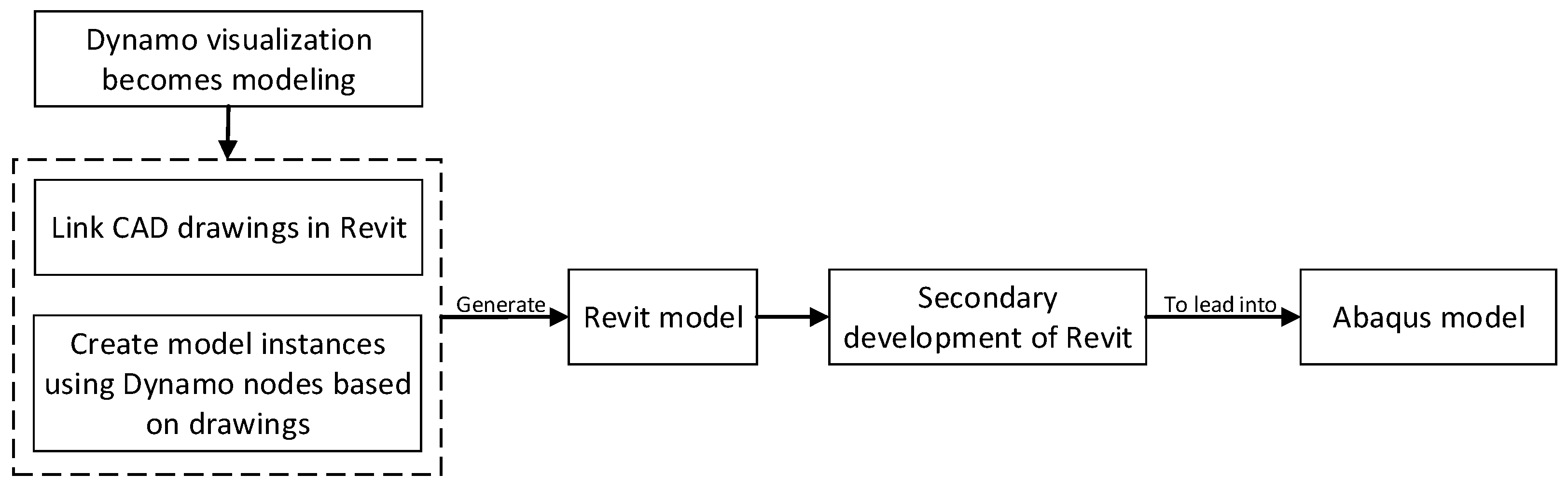
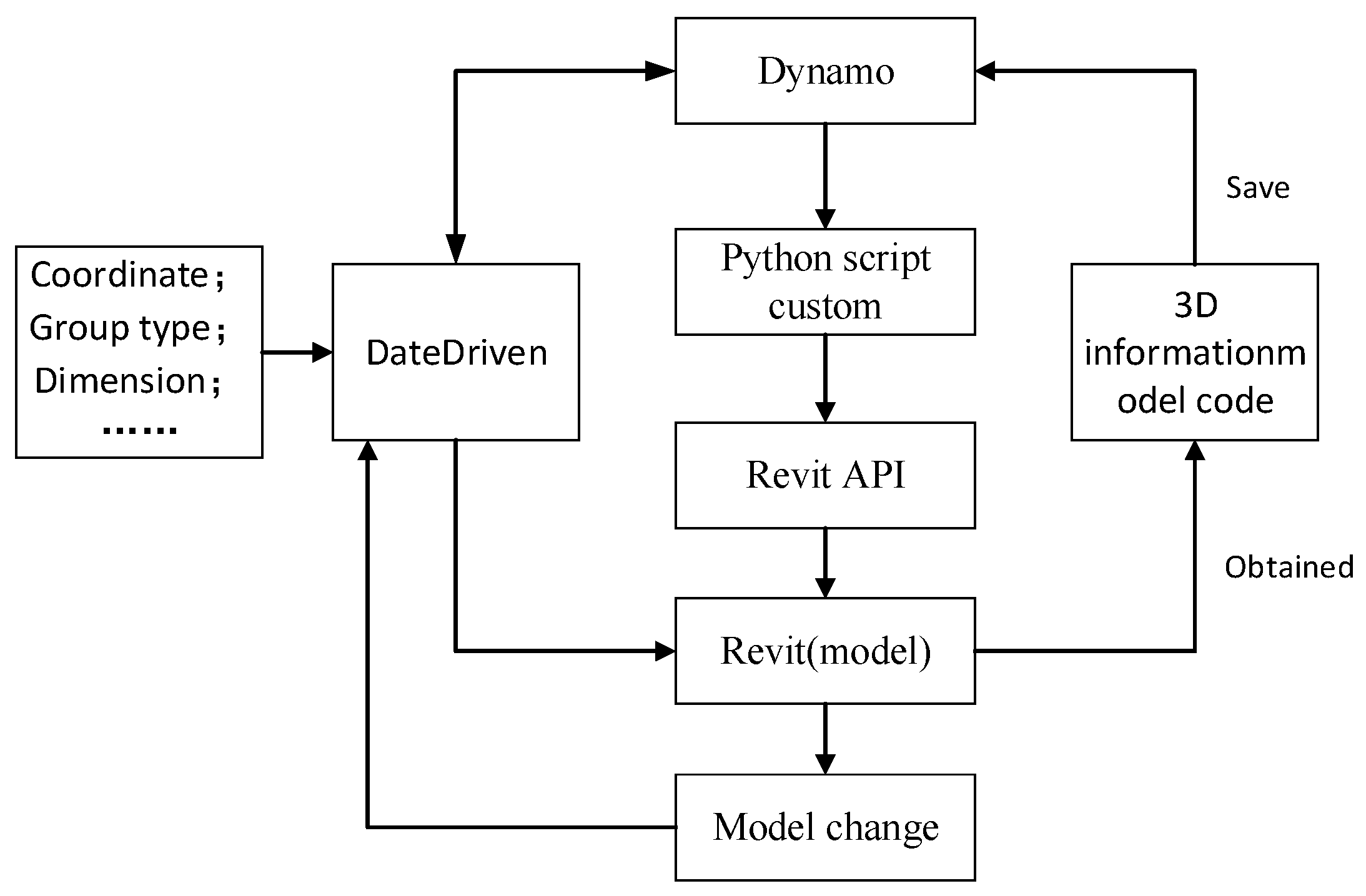
3. Dynamo Visual Programming Modeling Principles

Dynamo, a built-in plugin for Revit 2017 and later, provides direct access to Revit API and parametric interaction with Revit models to generate parametric models. Dynamo’s graphical interface origin is the same as the origin of the Revit project template model, which means that when Dynamo reads a coordinate model in a Revit project, the display area follows the same coordinates. Through Dynamo preset nodes (or custom nodes created using Python 2.7 script), modeling elements of the Revit API interface can be parameterized, including location, family type, and size. Finally, Dynamo-driven data can generate 3D information model code of Revit projects and can be saved as a 3D information model in Revit, as shown in Figure 4. If the project needs the design to be changed at a later stage, then the relevant logical parameters in the Dynamo file just need to be adjusted and the program run, and Revit will be updated to the new model after the change under the drive of Dynamo.
The idea of parametric modeling based on Revit and Dynamo interaction mode is as follows.
In Revit, parametric modeling is realized through Dynamo, which relies on the definition of components by the Revit API. Workflow is created through Dynamo’s visual programming interface, and modeling tasks are automatically completed by directly calling the Revit API. The collaborative workflow of Revit and Dynamo includes: (1) Dynamo and Revit model data docking; (2) writing and saving model logic code in Dynamo; and (3) running Dynamo to trigger Revit to generate a 3D model.
The key steps of modeling in Dynamo include: (1) studying the structural elements of the model defined by the Revit API; (2) selecting the nodes (including function nodes and Python script nodes) needed to build the model structure; (3) obtaining and filtering the relevant data of the defined elements; and (4) running and saving the program to drive Revit to generate models.

4. Project Overview and Modeling Preparation

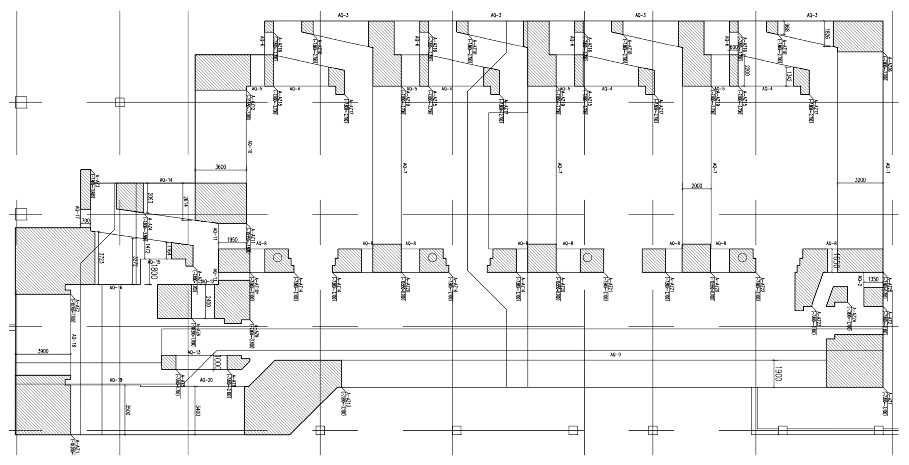
4.1. Project Overview

Xi’an International Medical Center Proton Hospital is located in the Xi’an High-tech Industrial Development Zone, covering an area of 25,880.4 square meters, with one underground floor (two local floors) and one aboveground floor. This study focuses only on the proton area of the proton hospital. In order to prevent the impact of radiation on the human body, most of the walls in the proton area are more than 1 m thick, with the thickest part reaching 3.9 m. The structure diagram of the proton region is shown in Figure 5.

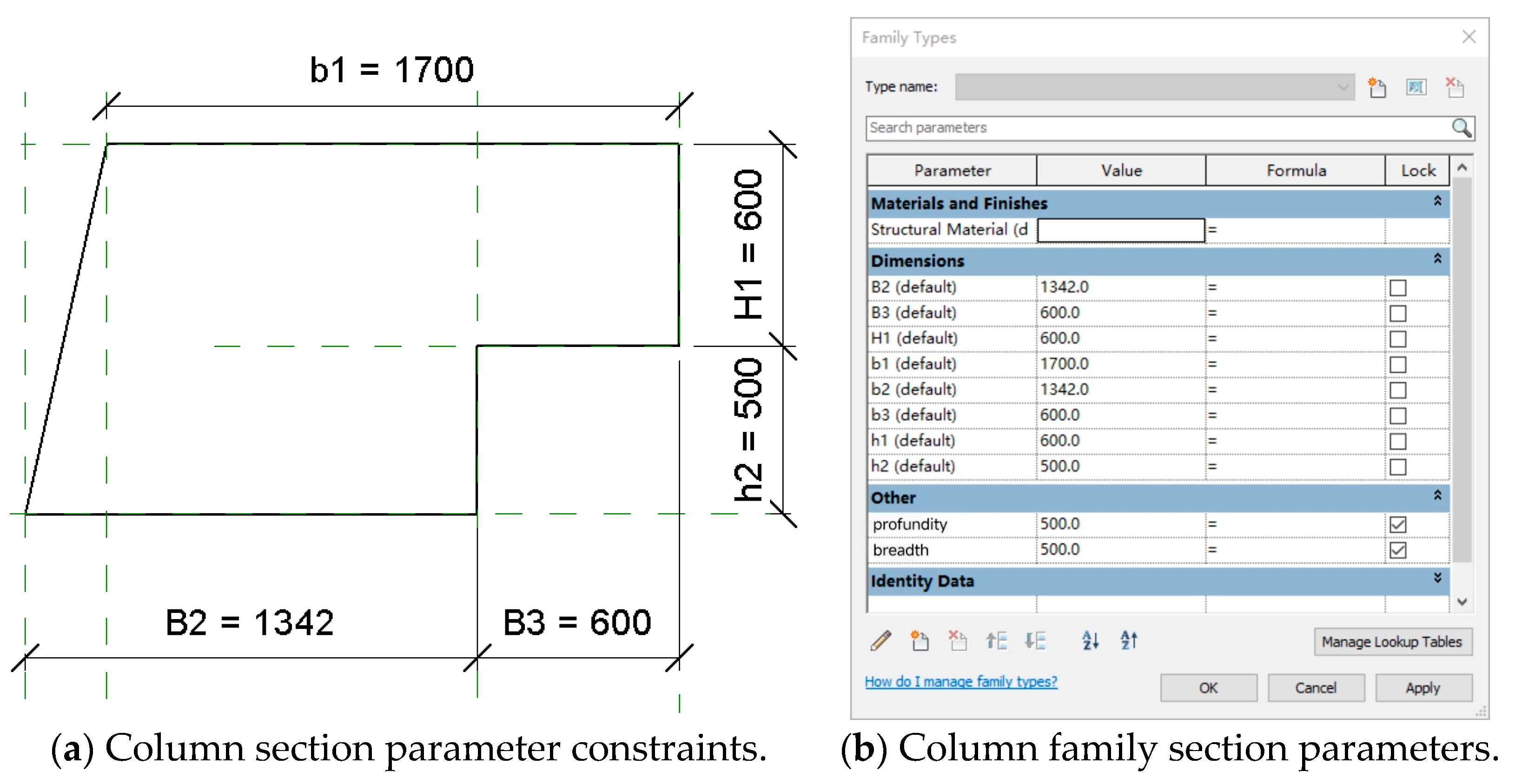
4.2. Create a Parameterized Family of Special-Section Columns

Due to the complex and variable cross sections of proton zone structural columns in the proton hospital, it is necessary to first create cross sections that are not in the Revit family library, such as the specially shaped cross-section columns shown in Figure 6.
First, based on the cross-section characteristics of the specially shaped columns, “metric structure column.rft” is selected as the family sample. Next, in the Working Plane view, use the Line or Rectangle tool to draw the bottom outline of the column and add parameters to control the dimensions as needed. Use the Stretch tool to create a solid model of the column based on the bottom outline, ensuring that the top and bottom constraints of the column are set correctly so that they can be properly aligned to the structural floor or other structural elements when placed in the project. At the turning point of the structural column, the horizontal and vertical reference planes are set and the alignment constraints are imposed by the “Lock” command. Then, dimension the section and set constraints, as shown in Figure 7a, and enter the parameter name and data using the “Add parameters” command to complete the parametric configuration. Lastly, material was assigned to the specially shaped section column, as shown in Figure 7b. The modeling method of other specially shaped section column families is the same, so it will not be described here. After the special-section column family is established, the family data can be directly called upon in the later modeling according to the needs of the work, and similar components can be established by just modifying the corresponding parameters.

5. Dynamo Proton Hospital Automatic Modeling Logic Code

5.1. Structural Column Modeling Process

When creating a structural column in Revit, the required elements, according to the Revit API, include the level, place point, and family type, as shown in Figure 8. In Dynamo, the “FamilyInstance.BypointAndLevel” node is used to model the structural column. This node is suitable for bulk layout components based on coordinates and elevation data information, and node information is shown in Figure 9. Its three inputs match the modeling elements required by the Revit API. Among these, “level” can be obtained by elevation selection nodes, and “point” and “familytype” need to extract the layer lines of structural columns from two-dimensional drawings and obtain them by geometric analysis of the layer contours. The contours of structural columns extracted from CAD drawings need to be processed by combining continuous curves into a group, constructing polygons, and obtaining geometric center points and dimensions of structural columns through polygon geometric analysis. These data will be used as the basis for placement points and matching family types, respectively. Therefore, the parametric modeling of structural columns can be divided into specially shaped column modeling and rectangular column modeling.

5.1.1. Dynamo Parametric Modeling of Specially Shaped Section Column

(1)
Obtain the profile of the specially shaped structural column
First, link the proton hospital CAD drawing in Revit, then open Dynamo in administration. Use the “CAD.CurvesFromCADLayers” node directly in the Dynamo environment (as shown in Figure 10) to read the link file directly and obtain the line data for the specific layer name. Since data may be lost during file transfer, in order to ensure that the desired layer names and data formats are accurately obtained, the “CAD.LayerNames” node can be used to preview the names and order of all layers in the program. Use the “code block” node to select the structure column layer and transfer the target layer data to the corresponding port. In this example, the structure column layer is x[28]. Then connect the “Flatten” and “Group Curves” nodes to obtain the curves of the graph element and flatten them to a one-dimensional list. Finally, connect the “List.Count” node and obtain the sublist items using the node level <@L2>, which is used to determine the graphic criteria by which the graph can be filtered, as shown in Figure 11.
(2)
Calculate the specified corner coordinate data of the profile column section
When extracting the profile of the column section, we obtain a series of straight lines rather than a closed polygon structure, and the geometric analysis needs to be based on the closed figure. Therefore, these line segments must be converted to polygon format. In this process, we first need to make sure that we are extracting pure column profiles from the CAD layer. This can be achieved by using the “List.FilterByBoolMask” node, which can exclude graphs with fewer than six polygon edges (six is the number of sides of a specific column). Then, use “curvely.startpoint” to obtain the starting point of each line to determine the corner points of the polygon. Using the “Polygon.ByPoint” node, create polygons based on these corner points. Finally, use the “list.getitematIndex” node to select the first corner from the corner List and set the index to 0. Figure 12 shows the node configuration diagram.
(3)
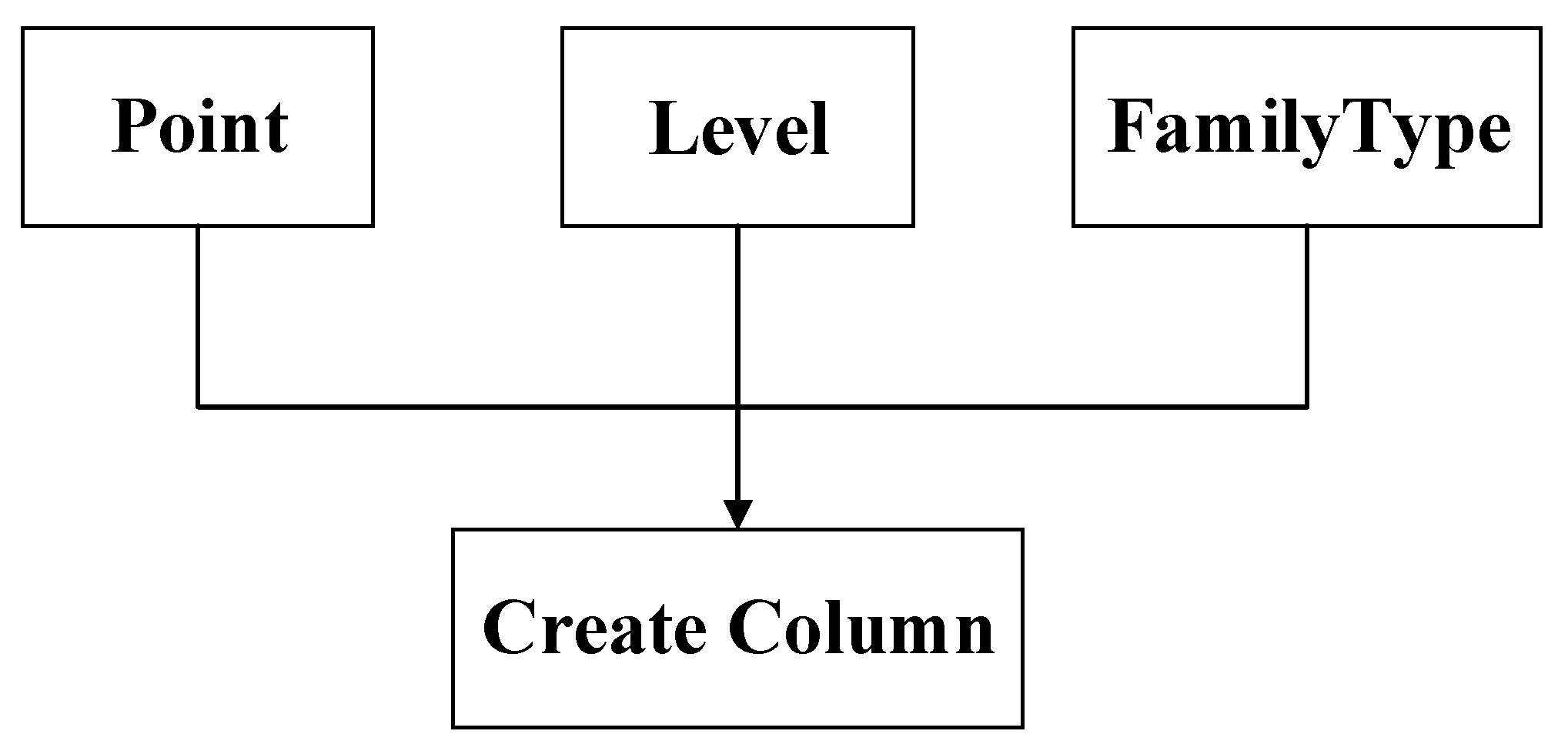
Generate specially shaped column model
Use the FamilyInstance.BypointAndLevel node created column structure model, the structure of the column type, and the column section first corner point coordinate data access input, and specify the corresponding level. Execution can be generated after the structure model of the column. Figure 13 shows the node configuration. The specially shaped column model generated is shown in Figure 14.

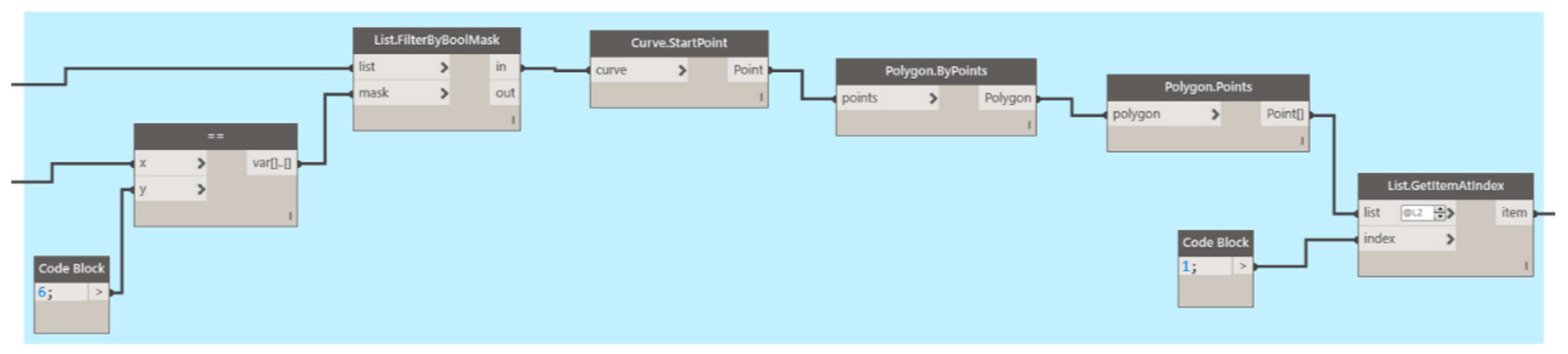
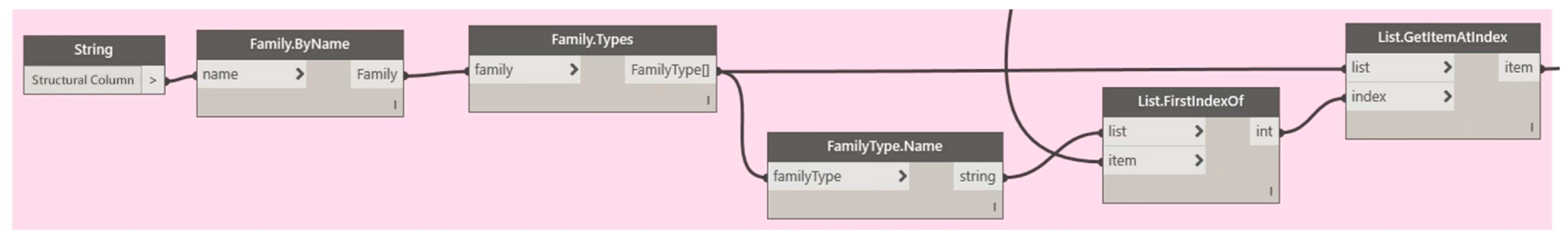
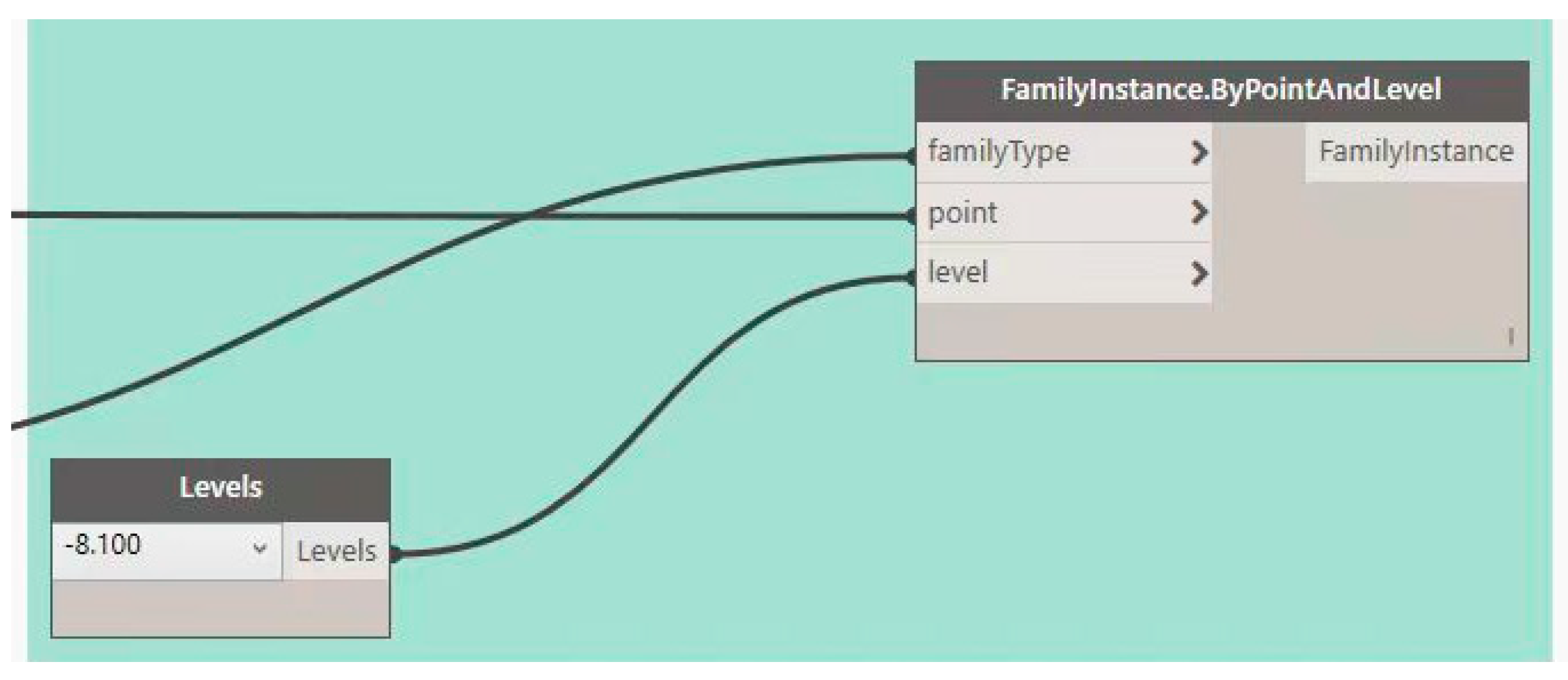
5.1.2. Dynamo Parametric Modeling of Rectangular Section Column

(1)
Obtain the outline of the structural column
As shown in Section 5.1.1 (1) of this study.
(2)
Calculate the coordinate data of the center point of the section of structural column
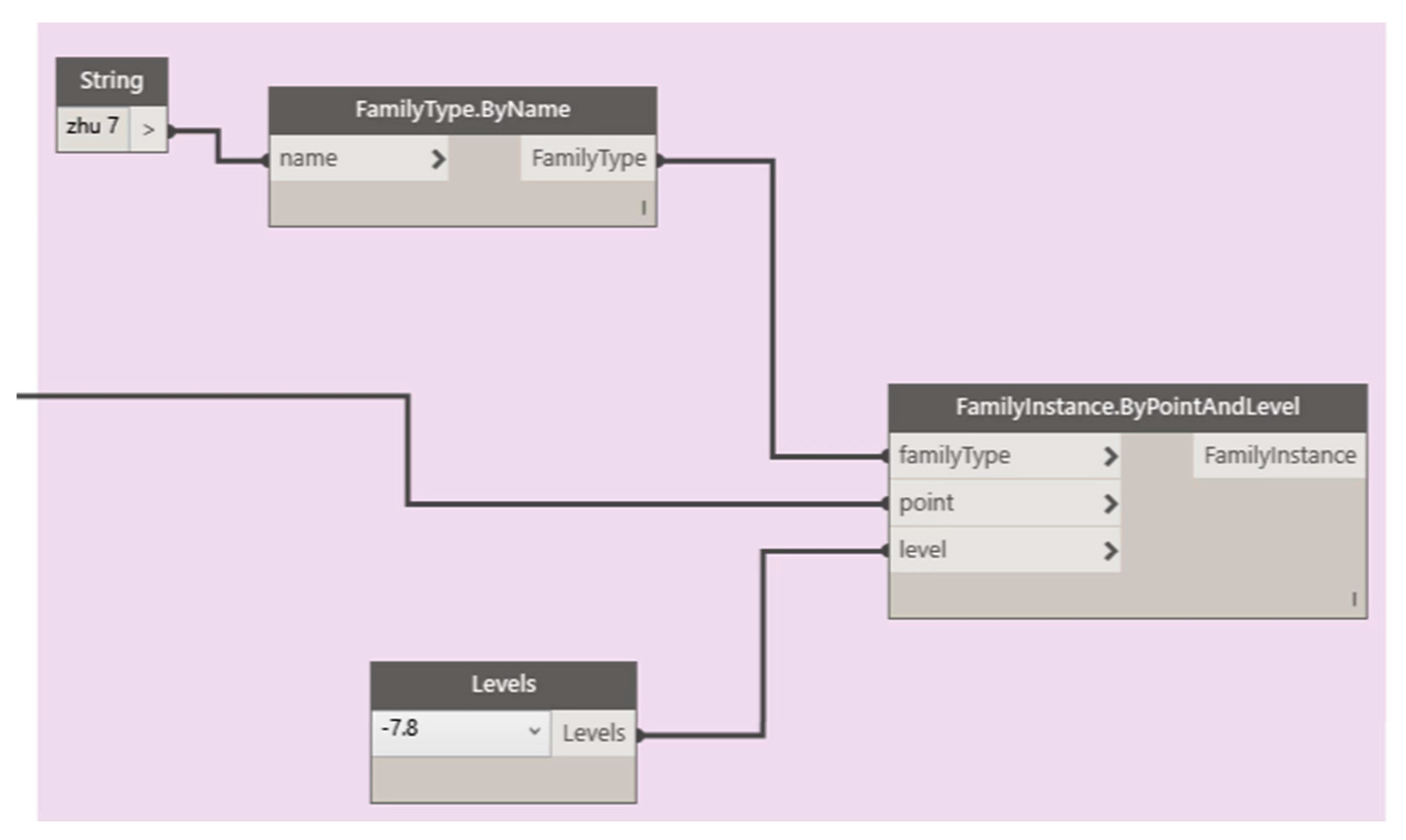
Convert the obtained contours to polygon format according to the previous steps in order to calculate their center points. In this process, we first need to ensure that we are extracting pure column cross-section outlines from the CAD layer. This can be done by using the “list.filterbyboolMask” node to filter out the list items with fewer than four polygon edges (non-rectangular). Then, use “curvely.startpoint” to obtain the starting point of each line to determine the four corner points of the rectangle. Then use the “Polygon.ByPoint” node to create polygons based on these corner points. Finally, the position of the center point of the polygon is calculated through the “polygon.center” node by taking the average of the coordinates of the four vertices. Figure 15 shows the node configuration.
(3)
Obtain the length and width of the structural column
Using the “Rectangle.ByCornerPoints” node, the rectangle is defined according to the starting point coordinates of the column section outline. Then, the Height and Width of the Rectangle are extracted through the “Rectangle.Height” and “rectangle.Width” nodes, and rounded to an integer form, and the rectangle length and width are obtained using the “Math.Round” and “String from Object” nodes, and converted to text. However, Dynamo’s “Math.Round” node generates a floating point number with two decimals, such as 300.00 instead of 300. To eliminate the decimal part, first convert the value to a String, then use the “string.split” node to take the decimal point “.” Delimit splits numbers to form a list of integers and fractional parts, the first part of which is the desired integer. By setting the “List.FirstItem” node to the <@L2> level, you can extract the first item of the level list. Finally, the “Code block” node merges the width and height data into a format of “XXXxXXX mm”, such as “350 × 400 mm”, and saves this data sequence to the TableC list. Figure 16 shows the node configuration.
(4)
Size data matching structure column family type
Select the name of the structural column family to collect all the type names of the family in the project, build the family type list output by “Family.Types”, and name it TableA. Next, convert the family type names in Table 1 into string format, create a new list, and name it TableB. Using the rectangular size data TableC captured by the program combined with the function of “List.firstIndexof” to compare with the string of family-type names in TableB, a list containing corresponding index values is generated and named TableC2. Finally, the function of “List.GetItemAtIndex” is used to retrieve the corresponding family type names from TableB according to the index values in TableC2, and a list of family type names matching the column cross-section contour data is formed, named TableD. These tables are generated by Dynamo nodes. Figure 17 shows the node configuration.
(5)
Generate structural column model
Use the FamilyInstance.BypointAndLevel node created column model structure, the structure column type TableD, and column section center coordinates data access input, and specify the corresponding level. Execution can be generated after the structural model of the column. Figure 18 shows the node configuration. The generated structural column model is shown in Figure 19.

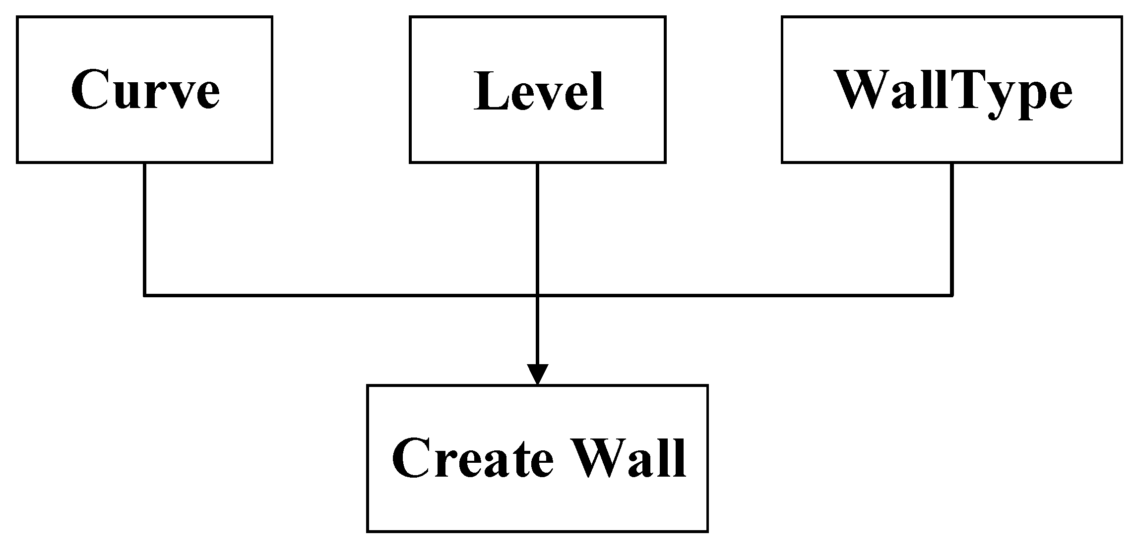
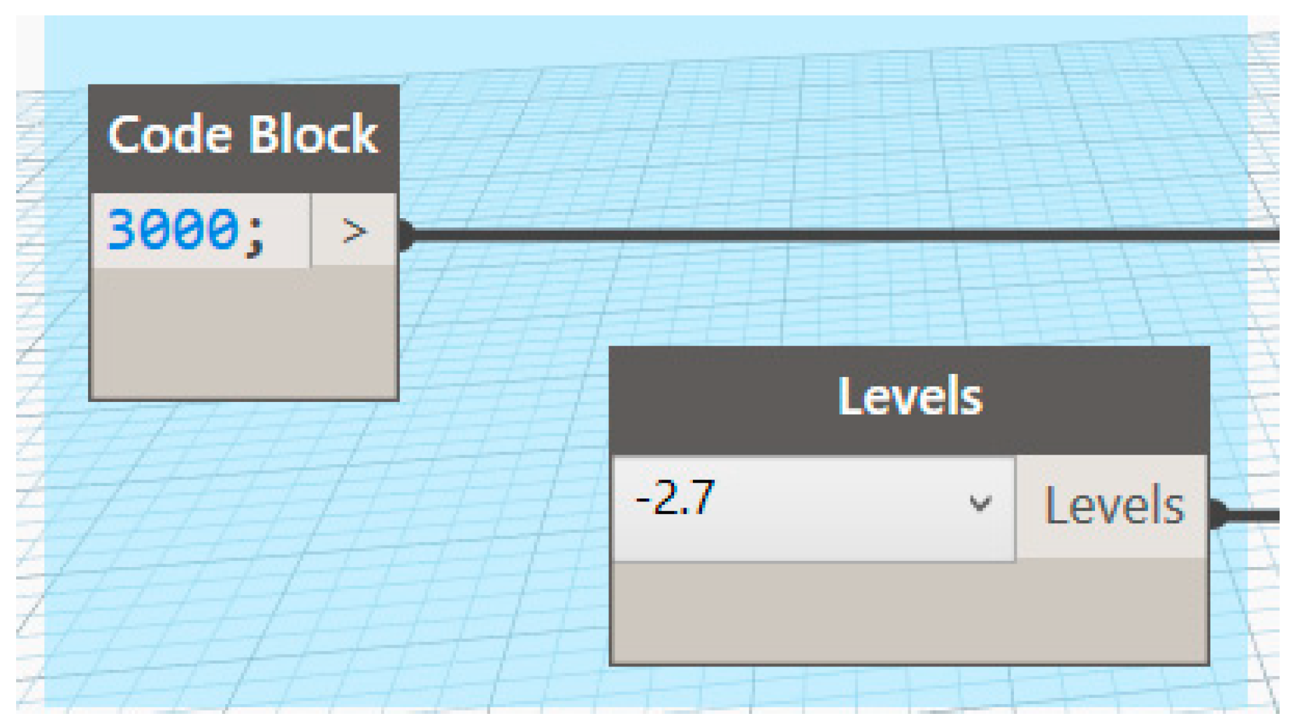
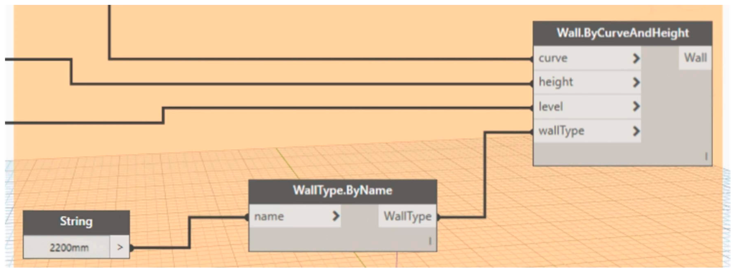
5.2. Structural Wall Modeling Process

Creating a wall in Revit requires the wall center line, base elevation, and family type, which correspond to the input information “curve”, “level”, and “WallType” of the “Wall.ByCurveAndHeight” node in Dynamo. This node is suitable for batch generation of standardized walls based on geometric curves and parametric properties, as shown in Figure 20. The reference elevation is selected according to the elevation of the drawing. The wall center line requires some processing on the drawing, then match with the type of wall family. Since there are many types of structural model walls in the proton hospital, the process of generating structural walls of different thickness by Dynamo visual programming is basically the same, so only one of them is shown here.
(1)
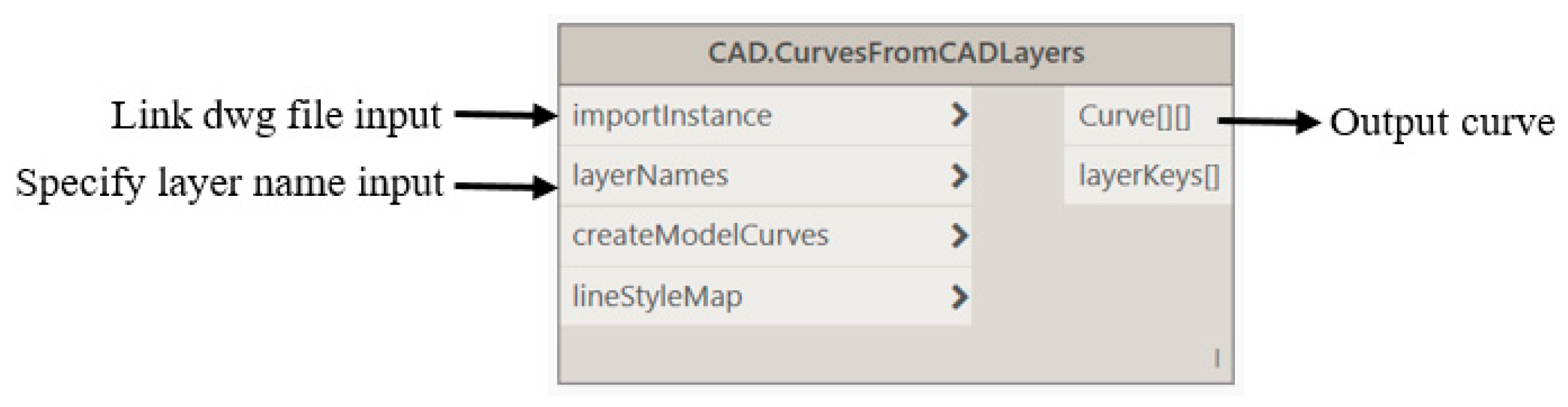
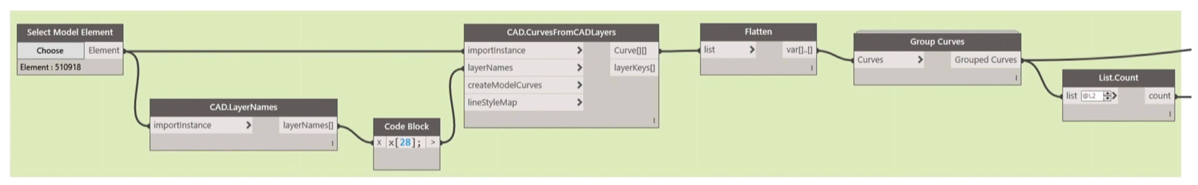
Read CAD objects and extract curve elements
Since there are many layer lines in the wall structure drawings and only the wall center line is required for modeling, CAD layer processing is carried out before Revit 2018 for the drawings, and layer lines other than the wall center line and special-section wall are deleted, as shown in Figure 21.
The processed CAD drawings are imported into Revit 2018 and decomposed into lines. Before starting to generate the structural walls, the “Select Model Elements” node is used to precisely select specific elements in the model. This usually involves selecting the curvilinear elements that represent the contours of the walls in the Revit model, which are the line elements obtained by breaking down the CAD drawings. This can be achieved automatically by clicking the “Select” button in the interface and then selecting the appropriate element in Revit View or by entering the ID of the element. After the model elements are selected, the next step is to use the “CurveElement.Curve” node to extract the curve information for those elements. This node extracts the curve data from the selected model elements, which are used to generate the base outline of the wall. Figure 22 shows the node configuration.
(2)
Set the height and elevation of the wall
The height of the wall is a key parameter, which can be set via the “Code Block” node. In this example, the height of the wall is coded as 3000 mm. This node allows the user to enter a specific value or to dynamically set the height from the output of other nodes. The elevation of the wall determines the vertical position of the wall in the building model. With the “Levels” node, the user can select a specific elevation, such as −2.7, to determine the bottom position of the wall. Figure 23 shows the node configuration.
(3)
Specify the wall type and generate the structural wall
The type of wall determines the material, performance, and other properties of the wall. In this example, the wall type is named “regular-2200 mm”, the “String” node is used to select the wall type, and the “WallType.ByName” node is connected, where the wall type can be specified by entering the name of the wall type. Then, call the node that creates the wall model “Wall.ByCurveAndHeight”, select the corresponding elevation, connect the wall center line and family type, and run to generate the wall model. Figure 24 shows the node configuration. The final wall model creation effect is shown in Figure 25.

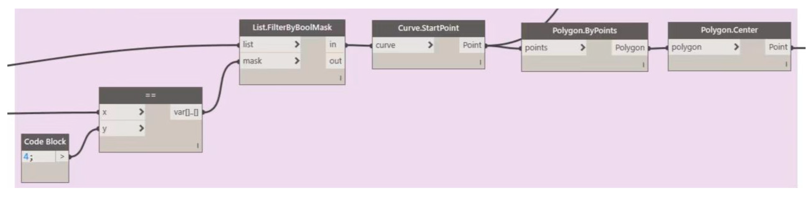
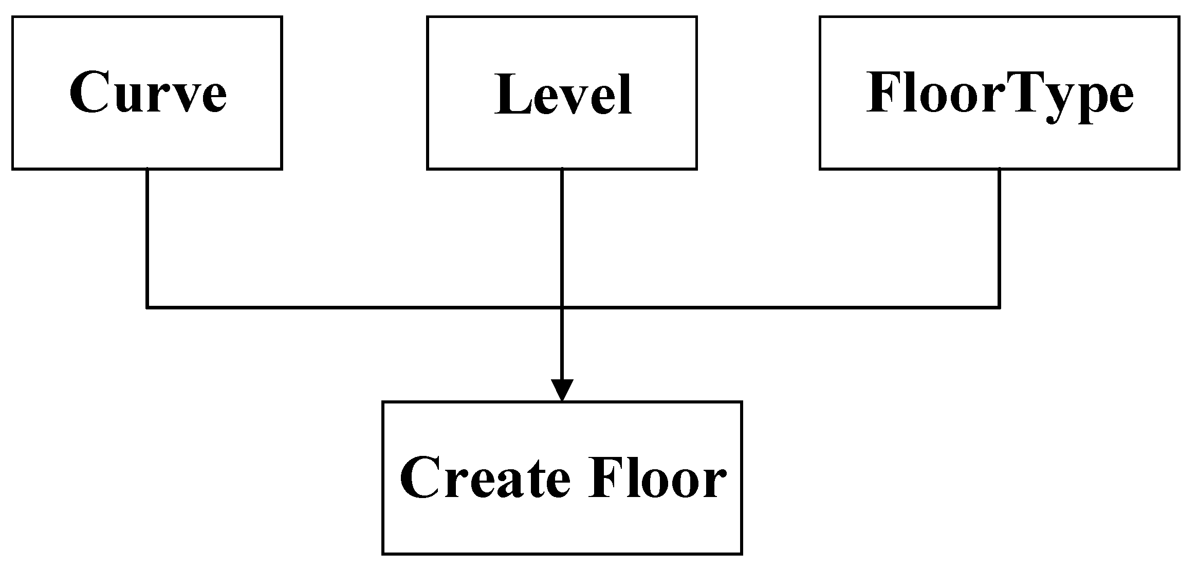
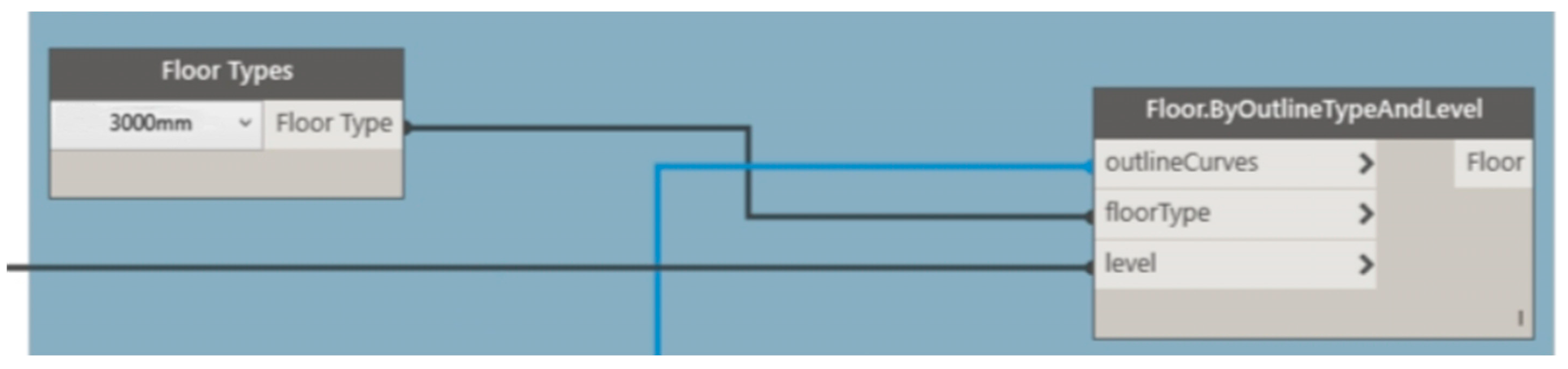
5.3. Structural Floor Modeling Process

In traditional floor modeling, the manual creation process is cumbersome, often requiring identification of the edges of structural columns and beams in combination with CAD drawings and then drawing closed contour curves in Revit to define floor boundaries. Through Dynamo, section planes can be generated using a structural column wall model and corresponding elevation view, edge contour curves can be extracted, and then floor models can be automatically generated, with necessary manual adjustments made according to drawings. In Revit, creating a floor requires a closed contour line, elevation, and floor type, which correspond to the input information “curve”, “level”, and “floorType” of the “Floor.ByOutlineTypeAndLevel” nodes in Dynamo. This node is suitable for batch generation of standardized floor slabs based on geometric profile and elevation information, as shown in Figure 26.
(1)
Obtain the floor boundary line
Call the “Select Model Elements” node to select all structural column wall models, convert them to entities via the “Element.Solids” node, and merge these component entities into one entity. Then, select the elevations of all target floors and use the “Level.Plane” node to obtain the elevations to create a plane. Then, through the “Geomet. Intersect” node, the merged entity is intersected with the created plane list so as to generate the surface of the section of the structural column wall of the corresponding floor. The point configuration is shown in Figure 27.
(2)
Filter the outermost contour line
On the wall and elevation of the structure column section (surface) extract contour line (curve), using “PolySurfac.ByJoinedSurfaces” nodes, connect multiple curve surface composition and reuse node calculation “PolySurface.UnconnectedBoundaries” not connected to the other surface of two-dimensional cell boundaries. Because there will be an extra set of outermost curves in the obtained contour line, these need to be removed by data processing. The outermost curve of each floor contour is usually the longest, so the outermost curve can be removed by deleting the longest line using the “cural.length” node. The “Curve.Length” node is used to sort all contour lines by length, the outermost contour curve is screened out by the “List.MaximumItem” node, and the floor contour data table is obtained by inputting it to “List.FilterByBoolMask”. The node configuration is shown in Figure 28.
(3)
Generate floor model
Using “Floor Types”, select the floor-type node, called node “Floor.ByOutlineTypeAndLevel”, and the connected floor contour list, floor type, and elevation can be run automatically, with node configuration as shown in Figure 29. The results after the automatic generation of the floor are shown in Figure 30.

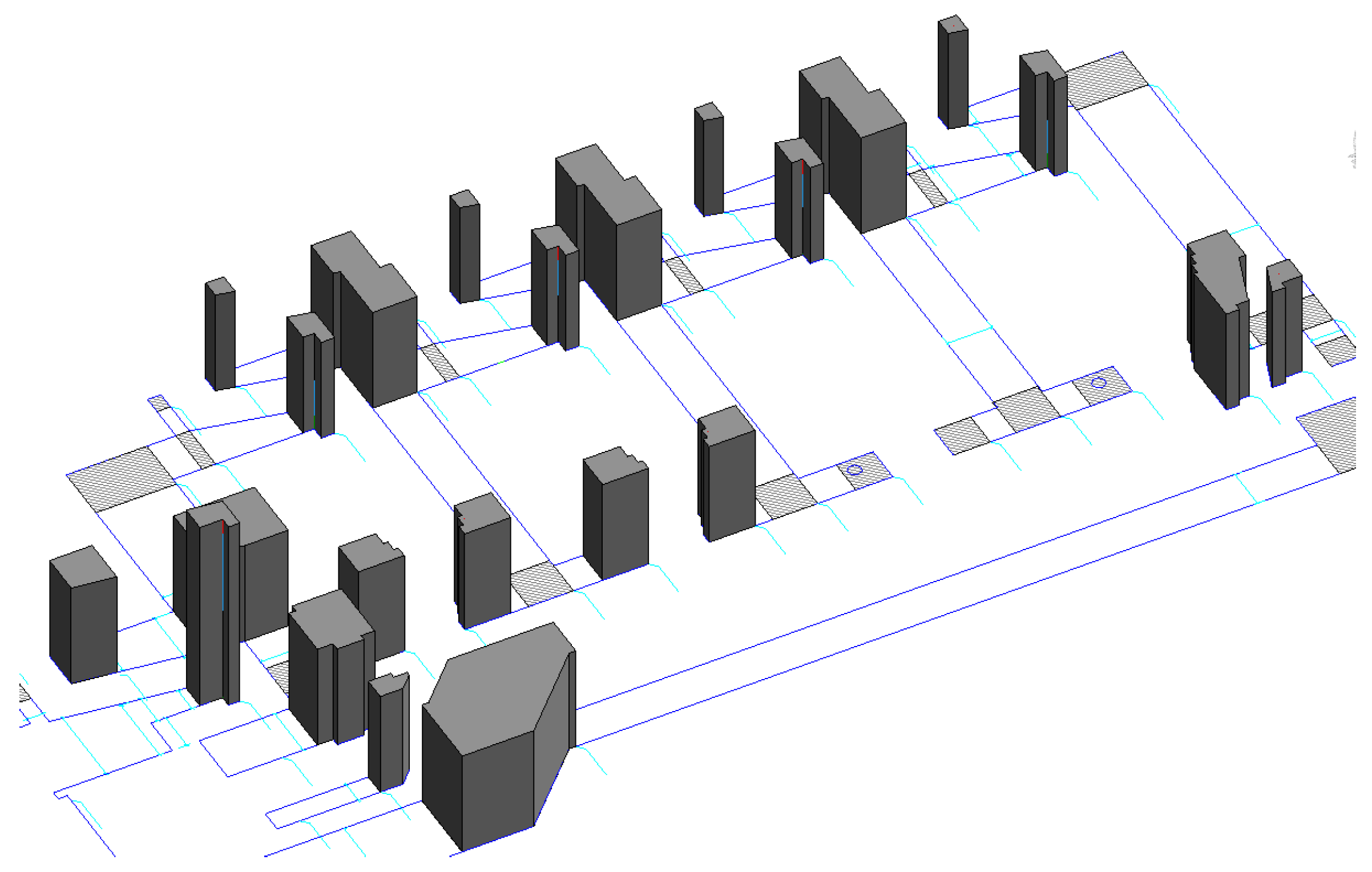
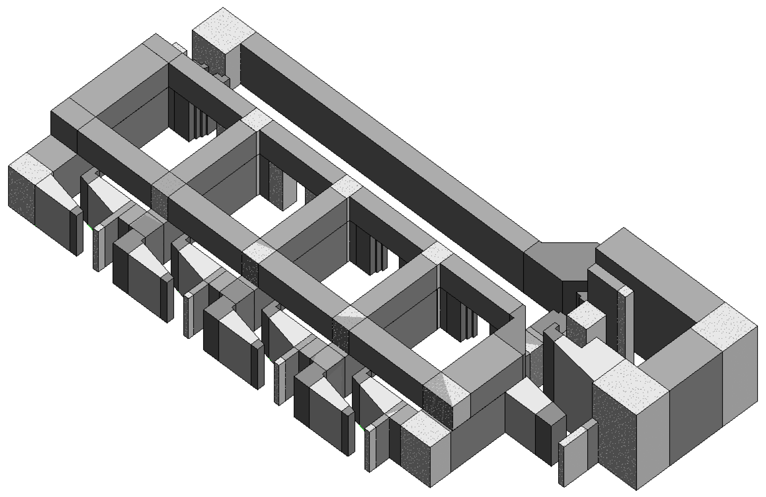
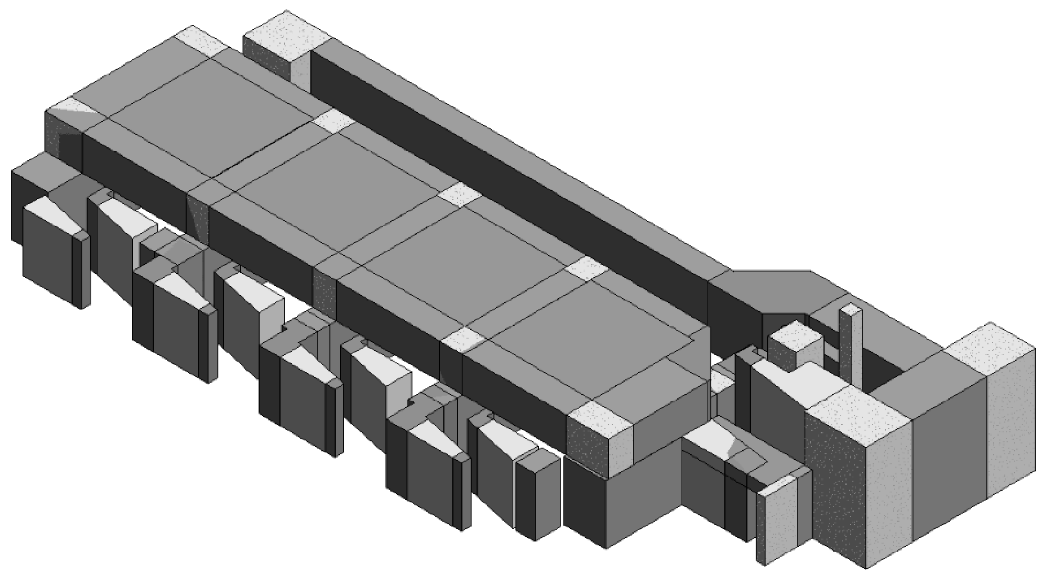
5.4. Generate Proton Hospital Parametric Model

Due to the uniqueness of the specially shaped section wall and the remaining floor slab, the floor type can be manually created according to the drawings, and then the model can be checked according to the drawings. The final overall model creation effect is shown in Figure 31.
Dynamo parametric modeling involves complex computation and data processing in multiple steps. First, data import and preprocessing require parsing and organizing the data, which involve data filtering. Secondly, the positioning and placement of the components requires precise geometric calculations and spatial analysis to ensure the correct placement of the components in the model. In addition, the generation of the model also needs to consider the geometric topological relations and spatial constraints of the components, which increases the complexity of the algorithm.
Parametric modeling of Dynamo is used to optimize data preprocessing and geometric calculation. The CAD data are cleaned and the invalid layer data filtered through the List.FilterByBoolMask node to reduce the amount of subsequent computation. String standardization is also carried out to convert dimensional data into a uniform format (such as 350 × 400 mm), avoid fuzzy matching, etc. The geometric calculation is optimized to use the polygon.center node to directly call the Revit API built-in algorithm to calculate the polygon center point, avoiding manual coordinate summation.
In general, Dynamo’s parametric modeling method significantly improves the efficiency and accuracy of modeling by means of automation and visualization, but its algorithm is also relatively complex, requiring high technical level in data processing, geometric calculation, and spatial analysis.

6. Revit–Abaqus Model Conversion Program Development

The main function of Abaqus/CAE, in addition to preprocessing and postprocessing, is to automate the process. The so-called process automation of Abaqus mainly consists in the following.
(1)
INP files
The most common way to develop Abaqus is through INP files. Writing INP files does have the advantage of simple syntax and low threshold, but its disadvantages are also very obvious, that is, the file structure is not flexible and cannot achieve some basic program logic operation functions (such as loop, judgment, etc.) [22]. INP files can achieve some basic operations in CAE, though with fewer functions.
(2)
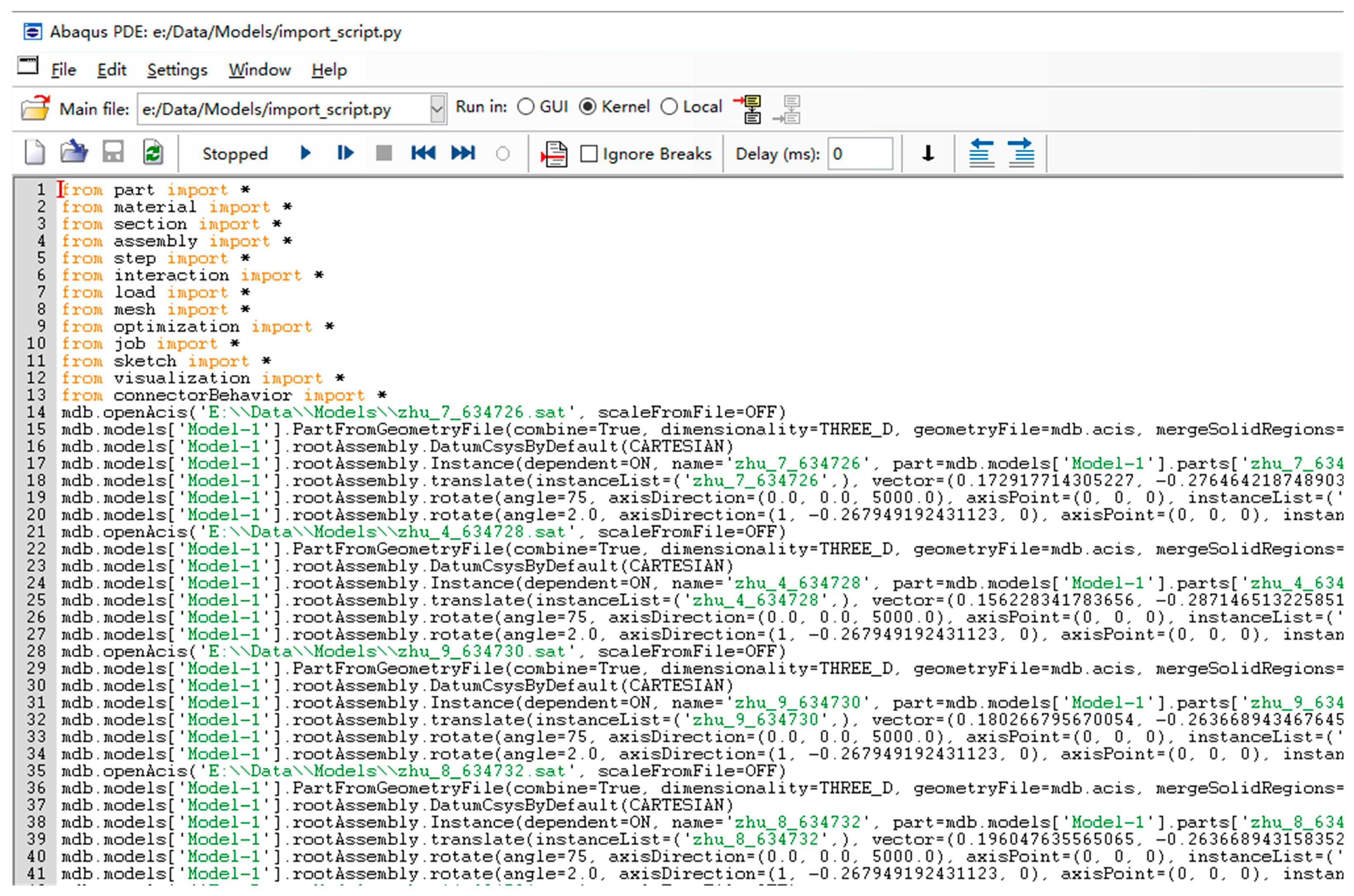
Python language script
Abaqus can implement various operations in CAE by running Python scripts. Abaqus provides Python with related secondary development modules for developers to call, possesses richer file features than INP, and can achieve more freedom of operation. Considering that the function to be implemented involves the import of files outside CAE, INP files can only call resources inside CAE, and external files cannot be imported, more powerful Python scripts for development must be chosen.
There is a common model file interaction format .sat(ACIS) between Revit and Abaqus for model import. There are many practical problems with exporting .sat files directly from Revit and loading them into Abaqus part models, as follows.
Model naming is confusing. Because the .sat file can only retain the geometry information of the Revit model, Abaqus automatically renames the parts in the order in which they were imported. If a small difference model such as a beam element is imported on a large scale, it is likely to appear in the wrong order, making it difficult to distinguish the problem.
(1)
The location information of the model is lost. Different types of model instances in Revit have different ways of representing positions. After studying Revit model instance data, it is found that the object in the location attribute of the general model is a subclass of LocationPoint, and its location is determined by a reference point coordinate. However, the object type in the location attribute of the structural framework model is LocationCurve, which indicates that the model is positioned by a curve. This approach is not a problem in Revit, but neither the .sat documentation nor the Abaqus program supports it. Therefore, when imported into Abaqus, the structural frame loses the position coordinates and placement of angle information. The conventional model also loses information about the placement angle. In fact, the problem and the naming confusion boil down to the same problem: missing parameter information in the .sat file transfer.
(2)
Model export filtering is missing. When you export a .sat file from Revit, the set of exported models is determined by the view. If you do not rely on the program, manual operation needs to manually select the exported model to be isolated into the corresponding view. If the number of models is large, the workload will be relatively large.
(3)
In general, the two problems of model naming confusion and model location information loss can be summarized as the problem of parameter information loss during model import. In the final analysis, it is difficult to adapt a .sat intermediate file to the data structure of various software. In order to solve these problems, the program developed in this paper manages the interaction of the model and uses Python script to realize the automatic generation of the Abaqus model. The core function of this script is to read .sat files of model components extracted from Revit, including key data such as spatial location and cross-section size. Based on these data, the model parts in Abaqus are created automatically. The orderly import function of the model carries relevant parameters. This provides a new idea for the effective import of Revit model into Abaqus.

6.1. Development Process of Model Transformation Program

When Revit exports .sat files, the set of exported models is determined by the view. If there are a large number of models without the help of programs, it will take a lot of work to manually isolate the exported models to corresponding views. In this study, Revit secondary development technology was used to write a program to export the selected model instance into a single .sat file and put all the saved .sat files into the same designated folder for unified storage. The program was used to automatically generate a corresponding Python script, which contained the path information and related parameters of all the .sat files. After Abaqus runs the script, the .sat file is automatically imported and named based on the script data. After the part is imported, the script automatically performs assembly operations based on location parameters. The model transformation program development process is shown in Figure 32.
The process of program design and implementation is as follows:
(1)
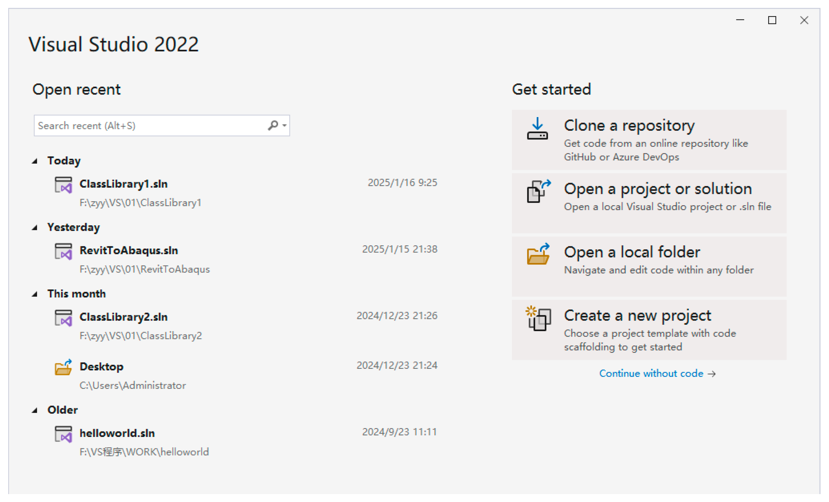
Create a new base in Visual Studio2022 .NET4.7 project, load the class library (. NET framework), and name it.
(2)
Add the RevitAPI.dll and RevitAPIUI.dll assemblies in the project reference options and change their properties to False. Add a namespace to the program interface, such as using Autodesk.Revit.
(3)
Add the TransactionAttribute transaction attribute to the command class.
(4)
Create a new IExternalCommand-derived class and overloaded function Execute() method. Write code.
(5)
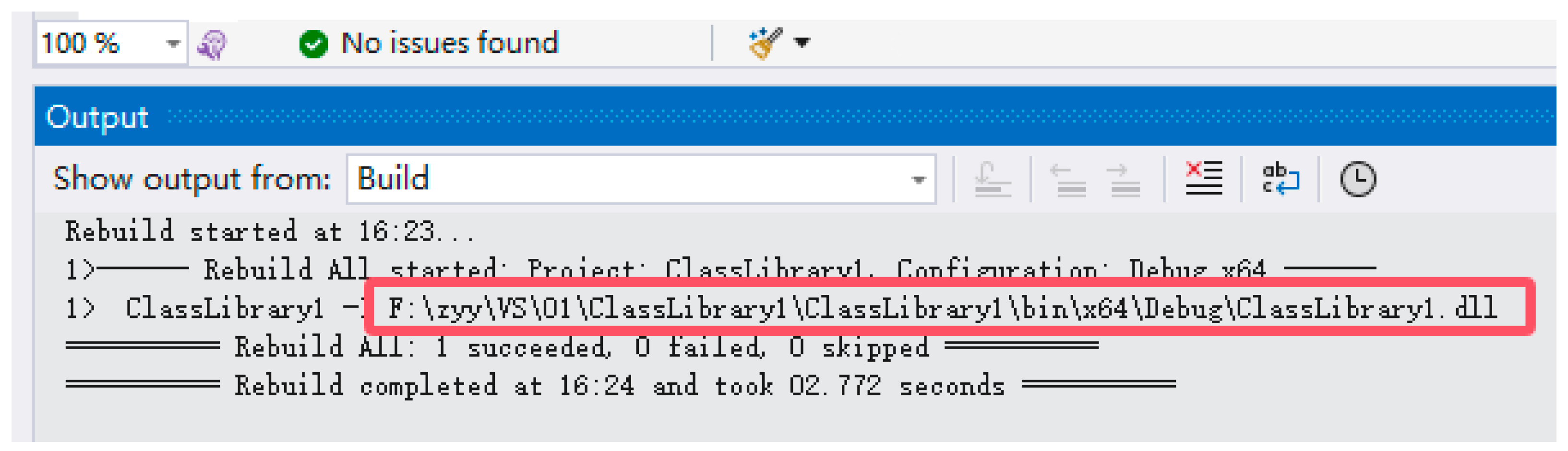
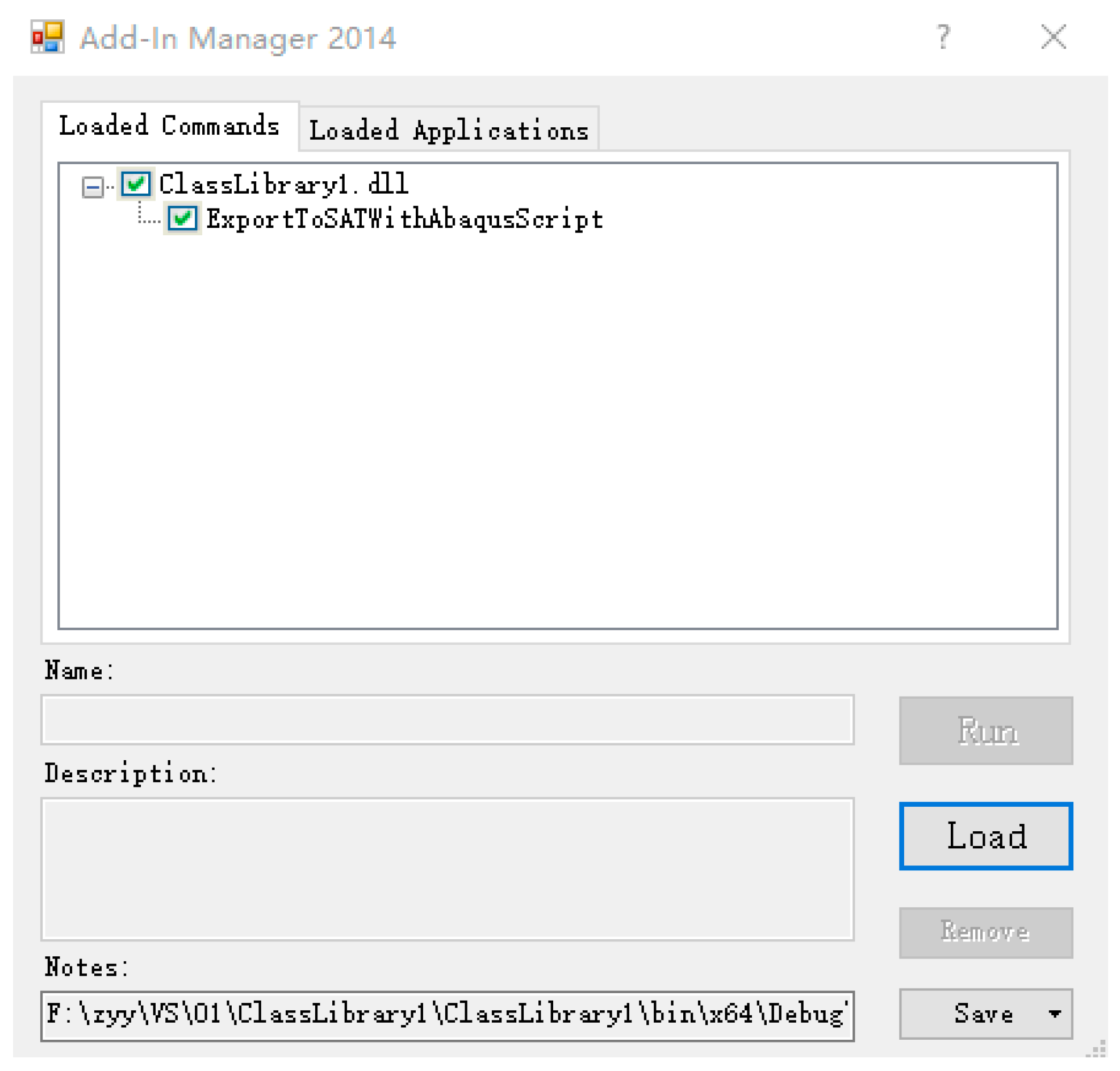
Generate.dll file after successful compilation, and debug the program in Revit.
(6)
After successful debugging, the .sat folder and its corresponding Python script conforming to Abaqus are generated.
(7)
Import the generated Python script into Abaqus and run it to verify that it meets the requirements.
In order to facilitate storing the exported model data, this article sets up the satModel class to store the exported model data. Between the model export method and the script generation method, this class will act as a transfer of data related to the model file. Table 1 shows the attributes set in the satModel class, where “string folderPath” indicates the storage directory path of the specified model export file, and “string elementName” indicates the name of the generated model that conforms to the file naming convention. “XYZ location” refers to the three-dimensional spatial coordinates of the recorded element in the building model. These are essential parts of the code flow. The code for obtaining the path of the .sat file and the name of the imported component is as follows:
string folderPath = @”E:\Data\Models”;
if (!Directory.Exists(folderPath))
{ Directory.CreateDirectory(folderPath); }
string elementName = element.Name.Replace(“ ,” “_”).Replace(“:,” “_”).Replace(“-,” “_”).Replace(.”,” “_”);
if (!char.IsLetter(elementName [0]))
{ elementName = “A_” + elementName; }
string satFileName = $”{elementName}_{id.IntegerValue}.sat”;
string satFilePath = Path.Combine(folderPath, satFileName);
Loop through all instances in the model, hiding all other instances, leaving only the model instance that needs to be exported separately, and then export its .sat file separately. Create the corresponding satModel data object based on its type and place it into a temporary storage list. Resume all instance displays before looping into the next instance element. In this way, each selected model instance is exported separately and its corresponding information is retained.
Once the model is exported, you need to create a Python script based on satModel. You first need to understand the basic components of importing the Python script, where “Part” and “Assembly” are the modules in Abaqus, as shown in Table 2. The code is written using the WriteLine method in the StreamWriter class, referencing the official Syatem.IO namespace. In this paper, only a few basic parameters are introduced to verify the feasibility of the method.
In the script creation method, we also need to involve some parameter calculation content. There is no complicated operation for the input of the coordinate parameters of the model—only the conversion of metric units can be done.

6.2. Verification of Model Transformation Methods

6.2.1. The Main Steps of Interface Development

Take the proton hospital concrete frame as an example. Build its 3D model in Revit and select it, as shown in Figure 31. Writing code in Visual Studio, the key code to obtain the .sat file is as follows:
using (Transaction exportTransaction = new Transaction(doc, “Export SAT File”))
{exportTransaction.Start();
SATExportOptions satOptions = new SATExportOptions();
doc.Export(folderPath, Path.GetFileNameWithoutExtension(satFileName), new List<ElementId> { tempView.Id }, satOptions);
exportTransaction.Commit();}
Copy the .dll file path generated after code compilation (see Figure 33), open the Add-In Manager external tool in Revit additional module, click “Load” to copy the copied.dll file path to the file name (Notes). Then, select “ExportToSATWithAbaqusScript” and click “Run”, as shown in Figure 34. After running the code in Revit, “Models exported and Abaqus script generated successfully!” is displayed, indicating that the specified .sat folder and corresponding Python scripts are generated as required. This example generates 116 .sat model files and 826 lines of corresponding Python scripts.
Open Abaqus, select the generated Python script in Abaqus PDE, and run it, as shown in Figure 35. An error may occur during the running. In this case, check whether the script points to the .sat file correctly or whether the .sat file is exported and named correctly. In addition, Revit model instance names need to be in English or numbers. Otherwise, Python scripts will also run incorrectly. In Revit, a single-story, single-span floor-space concrete frame was built, with a height of 3.5 m and a span of 5 m. C30 concrete was used for beams, plates, and columns. The model obtained by the conversion interface was imported into Abaqus, as shown in Figure 36, and a total of nine independent parts were generated, consistent with the number of model components in Revit.

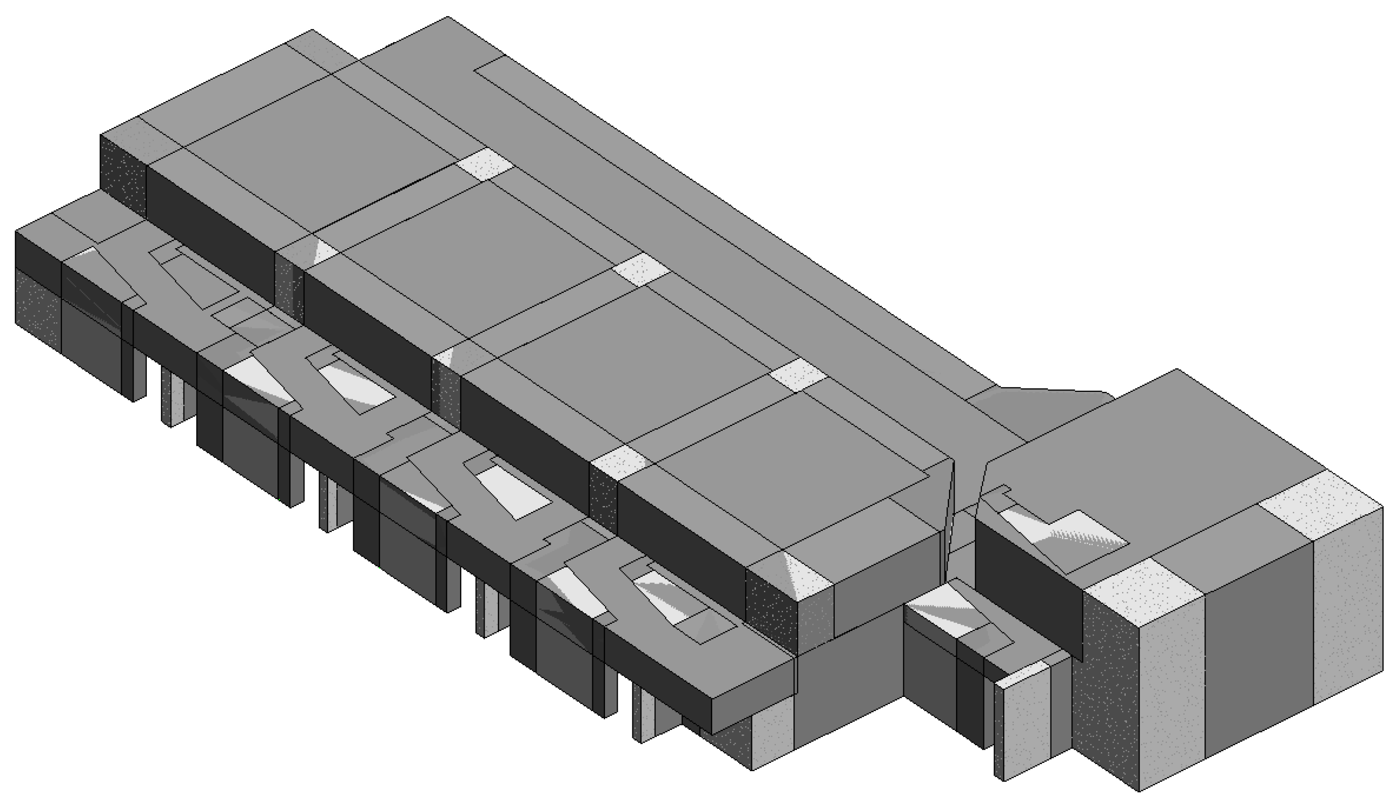
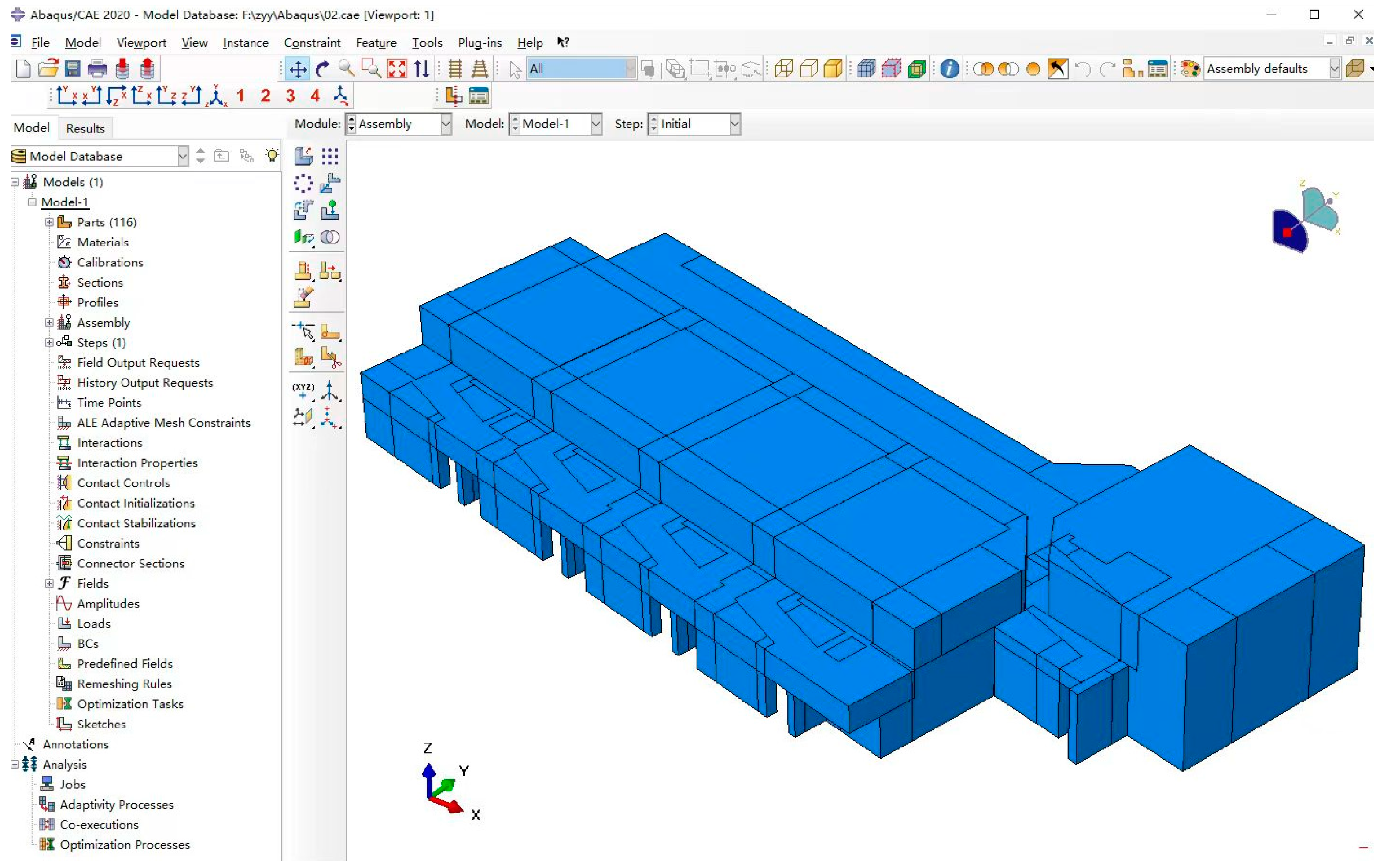
6.2.2. Proton Hospital Model Conversion

The model folder path was set according to the above process, and all models were selected for export. A total of 116 independent parts were generated in the Abaqus modeling interface Models, and the model was assembled according to the correct position, saving a lot of modeling time, as shown in Figure 37. From the whole conversion process, the use of plug-in conversion is faster, taking about 3 to 5 min. From the perspective of the transformed model entity, the model has a high degree of reduction and saves a lot of modeling time. The traditional modeling method of Abaqus is time-consuming and error-prone in the modeling of complex building structures. The model transformation and introduction method significantly improves the analysis efficiency and reliability of complex engineering problems, and makes up for the problem that Abaqus takes a long time in the modeling of complex engineering problems.
In terms of limitations of the current method, when Dynamo script processes very large building models (such as super-high-rise structures), node execution efficiency decreases significantly, memory usage increases exponentially, and there are compatibility differences between the intermediate file formats generated by different versions of Revit, so it is necessary to develop multi-version adaptation plug-ins. The potential direction of future work is to break through cross-platform compatibility, supporting multi-platform data exchange such as with Revit, Archicad, Tekla, etc.

7. Conclusions

This paper gives full play to the advantages of Revit in terms of its high efficiency, 3D visualization, and parametric modeling, and combines the powerful Revit API with the joint application of Revit and Dynamo to create a high-precision and efficient BIM information model, which is easy to adjust and operate.
(1)
By integrating Revit and Dynamo technologies, an automated and parameterized proton hospital structural modeling system was built, and Revit’s rapid modeling in proton hospital design was realized. This method significantly improves the conversion efficiency and accuracy from a traditional 2D design to a 3D BIM model, and provides strong technical support for the design and construction of complex engineering projects such as the proton hospital.
(2)
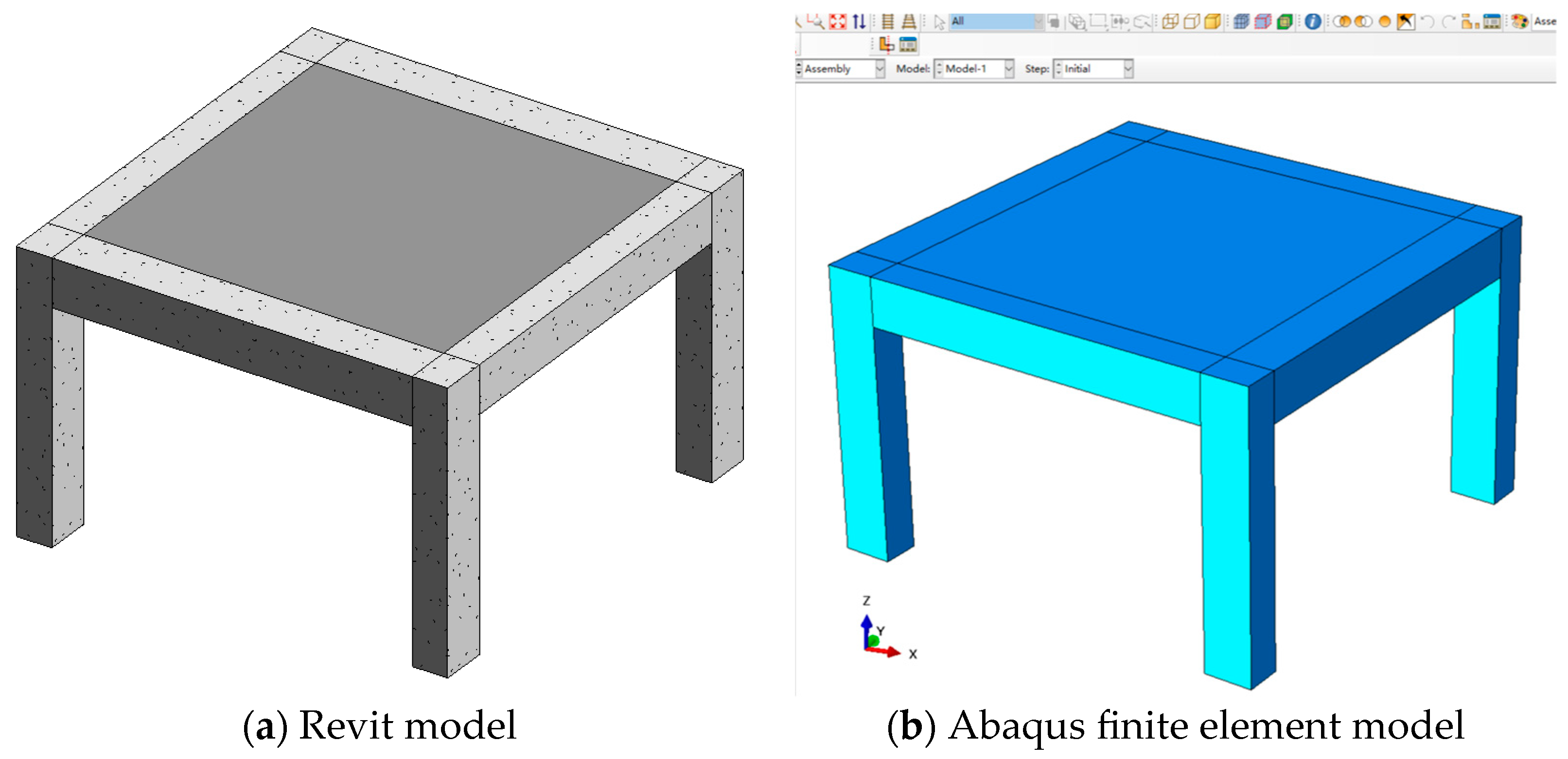
A structural model conversion interface between Revit and Abaqus was developed, and the feasibility of the model conversion method and the effectiveness of the model conversion program were verified through their application to the construction of a proton hospital. The method of directly converting the BIM model into the structural analysis model improves the modeling efficiency of the finite element analysis of the building structure and makes up for the shortcomings of BIM technology in the analysis of the building structure.
(3)
In the future, the acquisition and transfer methods of data information such as load parameters, boundary conditions, shrinkage, and creep during model conversion will be further improved, and a more efficient and comprehensive BIM-CAE model conversion program will be developed to provide a reference for solving problems such as information fault and repetitive work in the engineering design stage of the proton hospital.
(4)
This study systematically addresses the issues of privacy, compliance, equity, and environment in BIM-FEA interoperability by constructing a full-life-cycle ethics governance system.

Author Contributions

Conceptualization, S.L.; investigation, Y.L. (Yang Liu); methodology, W.Q.; software, Y.L. (Yan Li); validation, Y.Z.; formal analysis, T.Y.; resources, S.L.; data curation, B.L.; writing—original draft, S.L.; writing—review and editing, W.Q.; visualization, Y.L. (Yang Liu); supervision, W.Q.; project administration, T.Y.; funding acquisition, Y.L. (Yan Li). All authors have read and agreed to the published version of the manuscript.

Funding

This study was supported by the Natural Science Basic Research Program of Shaanxi Province (grant 2024JC-YBMS-446), the Construction Science and Technology Plan of Xi’an City (grant 2023-07), the Research and Development Project of China Construction Third Engineering Bureau (grant CSCEC3B-2024-28), and the Key Research and Development Project of Shaanxi Province (grant 2024SF-YBXM-618).

Data Availability Statement

The original contributions presented in the study are included in the article. Further inquiries can be directed to the corresponding author.

Conflicts of Interest

Authors Shoufu Li, Tao Yu, Yang Liu, Yan Li and Bo Lei were employed by the company China Construction Third Engineering Bureau Co., Ltd. The remaining authors declare that the research was conducted in the absence of any commercial or financial relationships that could be construed as a potential conflict of interest.

References

  1. Rodrigues, F.; Antunes, F.; Matos, R. Safety Plugins for Risks Prevention Through Design Resourcing BIM. Constr. Innov. 2021, 21, 244–258. [Google Scholar] [CrossRef]
  2. Zeng, Y.; Duan, R.; Huang, S.; Feng, T. Reliability Analysis for Complex Systems Based on Generalized Stochastic Petri Nets and EDA Approach Considering Common Cause Failure. Eng. Comput. 2020, 37, 1513–1530. [Google Scholar] [CrossRef]
  3. Yavan, F.; Maalek, R.; Toğan, V. Structural Optimization of Trusses in Building Information Modeling (BIM) Projects Using Visual Programming, Evolutionary Algorithms, and Life Cycle Assessment (LCA) Tools. Buildings 2024, 14, 1532. [Google Scholar] [CrossRef]
  4. Wei, Y.; Choi, H.; Lei, Z. A Generative Design Approach for Modular Construction in Congested Urban Areas. Smart Sustain. Built Environ. 2022, 11, 1163–1181. [Google Scholar] [CrossRef]
  5. Hamidavi, T.; Abrishami, S.; Ponterosso, P.; Begg, D.; Nanos, N. OSD: A Framework for the Early Stage Parametric Optimisation of the Structural Design in BIM-Based Platform. Constr. Innov. 2020, 20, 149–169. [Google Scholar] [CrossRef]
  6. Cho, J.; Kim, C.; Song, Y.; Kang, J.; Yeon, J. Lumped Record Management Method Using BIM and Dynamo for Spalling Maintenance. Autom. Constr. 2024, 160, 105324. [Google Scholar] [CrossRef]
  7. Zhang, Y.; Jiang, G.H.; Tang, S.Y.; Gu, C.L.; Tian, S.F.; Ma, T.X. Forward Intelligent Modeling Method of Aqueduct Based on Revit Secondary Development. Water Resour. Power 2024, 42, 137–141. [Google Scholar] [CrossRef]
  8. Rocha, G.; Mateus, L. Using Dynamo for Automatic Reconstruction of BIM Elements from Point Clouds. Appl. Sci. 2024, 14, 4078. [Google Scholar] [CrossRef]
  9. Wang, L.; Shi, H.; Li, Y.; Zhang, P.; Feng, C. Parametric Modeling of Urban Tunnel Foundation Pit Integrated with Revit and Dynamo. Chin. J. Undergr. Space Eng. 2023, 19 (Suppl. 1), 254–262. [Google Scholar]
  10. Godes, C.R.; Rodriguez, S.A.; Cho, J.; Song, Y.; Yeon, J. Optimizing Evacuation Efficiency in Buildings: A BIM-Based Automated Approach to Sustainable Design. Sustainability 2024, 16, 9240. [Google Scholar] [CrossRef]
  11. Wen, Z.; Luo, Y.; Wu, Q.; Fan, C.; Zhang, Q. Parametric Design of the Precast Concrete Slab with Truss Rebar Based on Dynamo. Build. Struct. 2022, 52, 128–132. [Google Scholar] [CrossRef]
  12. Carvalho, J.P.; Bragança, L.; Mateus, R. A Systematic Review of the Role of BIM in Building Sustainability Assessment Methods. Appl. Sci. 2020, 10, 4444. [Google Scholar] [CrossRef]
  13. Aziz, R.M.; Nasreldin, T.I.; Hashem, O.M. The Role of BIM as a Lean Tool in Design Phase. J. Eng. Appl. Sci. 2024, 71, 23. [Google Scholar] [CrossRef]
  14. Deng, X.Y.; Chang, T.Y.P.; Liu, X.L. Automatic Generation of Structural Model from IFC-Based Architectural Model. China Civ. Eng. J. 2007, 40, 6–12. [Google Scholar] [CrossRef]
  15. Liu, Z.Q.; Li, Y.G.; Lu, X.L.; Zhang, H.Y. BIM-Based Integrated Information Framework for Architectural and Structural Design Model. J. Tongji Univ. (Nat. Sci.) 2010, 38, 948–953. [Google Scholar] [CrossRef]
  16. Tang, F.; Ma, T.; Guan, Y.; Zhang, Z. Parametric Modeling and Structure Verification of Asphalt Pavement Based on BIM-ABAQUS. Autom. Constr. 2020, 111, 103066. [Google Scholar] [CrossRef]
  17. Jia, J.; Gao, J.; Wang, W.; Ma, L.; Zhang, Z. An Automtic Generation Method of Finite Element Model Based on BIM and Ontology. Buildings 2022, 12, 1949. [Google Scholar] [CrossRef]
  18. He, X.P.; Wang, H.; Zhang, Y.M.; Wang, F.Q.; Mao, J.X.; Xie, Y.S. Revit-Midas/Civil Model Conversion Approach and Its Application. J. Southeast Univ. (Nat. Sci. Ed.) 2021, 51, 813–818. [Google Scholar] [CrossRef]
  19. Zou, Y.; Hu, F.; Yang, H.; Cai, J.; Pan, H.; Zhang, Q. Detailed Design of Special-Shaped Steel Structures Based on DfMA: The BIM-FEM Model Conversion Method. Buildings 2024, 14, 1320. [Google Scholar] [CrossRef]
  20. Wang, X.X.; Huang, Y.L.; Zhao, J.C.; Duan, L.P. Development and Application of Revit-Abaqus Model Exchange Interface. J. Shanghai Jiaotong Univ. 2020, 54, 135–143. [Google Scholar] [CrossRef]
  21. Wang, J.; Wang, X. Research on Modeling Technology from AUTOCAD to REVIT. J. Eng. Technol. 2015, 7, 111–116. [Google Scholar]
  22. He, R.X. Research and Program Development of Curve Bridge Design Modeling Technology Based on BIM. Ph.D. Thesis, Chang’an University, Xi’an, China, 2023. [Google Scholar]
Figure 1. Visual Studio 2022 development interface.
Buildings 15 01658 g001
Figure 2. Add-In Manager plug-in operation page.
Buildings 15 01658 g002
Figure 3. Dynamo–Revit–Abaqus work flowchart.
Buildings 15 01658 g003
Figure 4. Dynamo and Revit interaction modeling principle.
Buildings 15 01658 g004
Figure 5. Structure plan of the proton zone.
Buildings 15 01658 g005
Figure 6. Schematic diagram of structural columns in the proton therapy area (truncated).
Buildings 15 01658 g006
Figure 7. Parameterization of shaped section columns.
Buildings 15 01658 g007
Figure 8. Structure column model definition element diagram.
Buildings 15 01658 g008
Figure 9. Structure column model to create nodes.
Buildings 15 01658 g009
Figure 10. CAD.CurvesFromCADLayers node.
Buildings 15 01658 g010
Figure 11. Obtain the outline code of the structure column.
Buildings 15 01658 g011
Figure 12. Calculating the coordinate data code of the first corner of the profiled column.
Buildings 15 01658 g012
Figure 13. Generate the structural column model code.
Buildings 15 01658 g013
Figure 14. Generating a specially shaped column model.
Buildings 15 01658 g014
Figure 15. Data code of the center point of the calculation structure column.
Buildings 15 01658 g015
Figure 16. Obtain the length and width data code of the structural column.
Buildings 15 01658 g016
Figure 17. Size data matching structure column family-type code.
Buildings 15 01658 g017
Figure 18. Generating the structural column model code.
Buildings 15 01658 g018
Figure 19. Generating a structural column model.
Buildings 15 01658 g019
Figure 20. Structural wall model definition element diagram.
Buildings 15 01658 g020
Figure 21. Example of structural wall modeling drawing format.
Buildings 15 01658 g021
Figure 22. Obtaining the model element and extracting the curve element code.
Buildings 15 01658 g022
Figure 23. Set the height and elevation code of the wall.
Buildings 15 01658 g023
Figure 24. Specifying wall type and generating structural wall code.
Buildings 15 01658 g024
Figure 25. Generating a structural wall model.
Buildings 15 01658 g025
Figure 26. Structural floor model definition element diagram.
Buildings 15 01658 g026
Figure 27. Obtaining the floor boundary code.
Buildings 15 01658 g027
Figure 28. Filtering the outermost contour code.
Buildings 15 01658 g028
Figure 29. Automatic generation of floor code.
Buildings 15 01658 g029
Figure 30. Automatic floor rendering.
Buildings 15 01658 g030
Figure 31. Overall model creation effect.
Buildings 15 01658 g031
Figure 32. Model transformation program development process.
Buildings 15 01658 g032
Figure 33. .dll file path generated after code compilation.
Buildings 15 01658 g033
Figure 34. Add-In Manager external tool.
Buildings 15 01658 g034
Figure 35. The generated Python script displayed in Abaqus PDE.
Buildings 15 01658 g035
Figure 36. Model transformation results.
Buildings 15 01658 g036
Figure 37. Proton hospital structure model introduced into Abaqus.
Buildings 15 01658 g037
Table 1. satModel class attributes.
Attribute ClassAttribute NamingAttribute Meaning
stringfolderPathSat file path
stringelementNameThe name of the import component
XYZLocationComponent placement reference point information
Table 2. Generating the components of a Python script.
ComponentFeature
Import moduleImport the Python module provided by Abaqus
Import modelExample Import the .sat file in the specified path to Abaqus
Create PartCreate the corresponding Part in the name of the elementName parameter
Import AssemblyImport the Part into Assembly
Disclaimer/Publisher’s Note: The statements, opinions and data contained in all publications are solely those of the individual author(s) and contributor(s) and not of MDPI and/or the editor(s). MDPI and/or the editor(s) disclaim responsibility for any injury to people or property resulting from any ideas, methods, instructions or products referred to in the content.

