1. Introduction
In recent years, with the continuous development of the country, the construction of infrastructure has become the focus of national attention. More and more long-span bridges have emerged. In recent years, mass concrete has gradually become the focus of attention in the engineering field due to its wide application requirements. In general, if the minimum size of the concrete structure reaches or exceeds 1 m, or the internal and external temperature difference is too large due to the hydration heat of cement, there is a risk of cracking. This can be classified as mass concrete [
1].
In the process of bridge construction [
2], the core of ensuring the quality of mass concrete is the effective control of temperature. Due to the limited thermal conductivity of concrete, it is difficult to diffuse internal heat in a timely manner; the internal temperature will therefore rise sharply during the hydration reaction. Subsequently, as the ambient temperature decreases, the concrete is affected by internal and external constraints, creating an uneven cooling process. The internal constraints are caused by the mutual constraints between the various parts of the concrete itself, while the external constraints may come from the surrounding solidified concrete or foundation, and these constraints will cause temperature stress. In some cases, the stress caused by temperature changes [
3] may exceed the stress caused by external loads, thereby increasing the risk of cracks in concrete structures.
In recent years, the integration of artificial intelligence and intelligent construction technology has promoted innovative breakthroughs in the field of concrete structure monitoring and construction control. At the level of structural monitoring, the deep neural network-attention mechanism fusion model developed by the Wang team [
4] achieves accurate prediction of the nonlinear displacement behavior of continuous rigid frame bridges through historical monitoring data, which significantly improves the generalization ability under dynamic conditions. Li’s team [
5] innovatively combines convolutional neural networks with infrared thermal imaging technology to construct an intelligent identification system for concrete cracks, which provides an efficient visualization solution for early damage diagnosis. Although these data-driven technologies focus on structural response monitoring, their core goal of enhancing structural safety and state awareness has formed a technical synergy with the temperature control and stress control studied in this paper.
In the structural health monitoring system, the identification of outliers is a key step. Abnormal values may come from sensor errors, environmental interference or other external factors. If these abnormal data cannot be eliminated in time, it will affect the accuracy of establishing a health baseline, and then interfere with the effect of damage detection. As WK Ao etc. [
6] discussed the authenticity and stability of monitoring data can be effectively guaranteed by systematically evaluating commonly used methods (such as minimum covariance discrimination). Similarly, the research by Connor O’Higgins etc. also pointed out that the use of a variety of anomaly detection strategies can help to improve the recognition rate of the basic model for early abnormal changes in damage. As the mass concrete temperature control system also relies on high-quality temperature monitoring data, this study introduces a similar anomaly detection idea in the data preprocessing stage. We draw on the theoretical methods of the above literature to ensure that the abnormal data are effectively eliminated when establishing the temperature field health baseline so as to provide a reliable basis for the optimization of the subsequent temperature control strategy.
In addition to static crack control, temperature changes also have a significant impact on the dynamic performance of concrete structures, such as long-span bridges. The ambient temperature and internal temperature gradient will change the material stiffness, prestress effect, and mass distribution, and then cause changes in the natural frequency, damping ratio, and vibration mode of the structure. A number of studies have revealed the mechanism of this coupling effect and its challenge to the accuracy of health monitoring.
Jin et al. [
7] reviewed the effects of temperature on vibration properties of bridge structures and pointed out that the changes in modal parameters due to temperature variations can be comparable to the effects of damage. Connor O’Higgins et al. [
8] developed a low-cost SHM system using MID methods, discussing the compensatory effects of temperature sensitivity through the optimization of input parameters. Rothschild A. Antunes et al. [
9] presented a case study at the SHMII-9 conference, demonstrating the effectiveness of temperature compensation strategies for modal identification using synchronized accelerometers. Connor O’Higgins et al. [
10] introduced a method to maximize the information obtained from low signal-to-noise ratio data by optimizing SSI-COV parameters, offering new insights for decoupling temperature effects from dynamic responses.
In addition, Dehui City is located in the northeast of China, which belongs to the severe cold climate zone [
11]. In this environment, low temperature conditions will accelerate the heat loss on the surface of the cap concrete, making it more prone to surface cracking due to the temperature difference effect. These cracks not only damage the weight-bearing capacity and appearance of the structure, but also may have a long-term impact on its safety and durability. Studies have shown that when the ambient temperature is lower than 5 °C, the mismatch between the internal hydration heat release rate and the surface heat dissipation rate of the concrete may cause a nonlinear temperature gradient, which in turn induces structural cracks. In order to cope with this challenge, scholars at home and abroad have proposed a variety of temperature control technologies. For example, the application of phase change material (PCM) provides a new idea for the temperature control of concrete in low temperature environment [
12]. Miao et al. incorporated microcapsule fossil wax into concrete and found that it can adjust the internal temperature fluctuation by absorbing and releasing heat, allowing the temperature difference to be controlled within 10 °C [
13]. In addition, in terms of material modification, the composite use of nano-SiO
2 and fly ash shows a good temperature control synergistic effect. Experiments show that the addition of 2% nano-silica can reduce the adiabatic temperature rise of concrete by 18% and increase the early tensile strength (Zhang et al., 2023) [
14]. However, the optimization of a cooling water pipe design in a low temperature environment is still a core engineering problem. Yuan et al. (2023) [
15] proposed through full-scale experiments that a metal water pipe with spiral fins to enhance heat transfer can increase the heat exchange efficiency by up to 30% and is suitable for extreme environments below −15 °C. In summary, the existing research focuses on the improvement of single temperature control measures, but there is still a lack of systematic analysis of the multi-factor synergistic mechanism of material modification.
Therefore, in this study, the temperature control and crack prevention measures of bridge mass concrete in severe cold areas are discussed in depth, including layered pouring, cooling water pipes and their layout, cooling water inflow speed, and other aspects. Based on this, this study realizes the real-time closed-loop correction of the thermal-mechanical coupling model in the construction process of mass concrete for the first time through the dynamic interactive verification of finite element analysis and on-site temperature monitoring data, and improves the simulation accuracy to the practical level of engineering. Aiming at the problems of large temperature difference and stress concentration caused by the hydration heat of mass concrete under the complex climatic conditions of high and cold climate, the temperature control bottleneck of the traditional one-time pouring process is broken through, and the coordinated temperature control system of ‘layered pouring-active cooling’ is innovatively proposed. On the one hand, layered progressive pouring technology is adopted. By releasing the hydration heat in stages, the temperature rise rate in the core area is reduced by 37%, and the phenomenon of temperature stress concentration is effectively alleviated. On the other hand, the metal cooling water pipe network is arranged in four directions inside the concrete, and the water parameters are dynamically adjusted according to the climatic characteristics, so that the peak temperature of the core area is reduced by 21 °C. Through the establishment of a temperature-stress dual control index system, numerical simulation and physical engineering verification show that the system successfully controls the maximum tensile stress within the safety threshold, and the crack incidence rate is reduced by more than 85%.
In order to improve the robustness of the system, a quantitative analysis method of parameter sensitivity is introduced to apply ±10% disturbance to key parameters, such as thermal conductivity and convective heat transfer coefficient. The results show that under the condition of extreme temperature difference fluctuation (−30~15 °C), the temperature control system can still maintain the technical standard of temperature gradient ≤18 °C/m in the core area. Subsequent research intends to integrate Bayesian model updating technology to construct a probabilistic prediction model that considers the time-varying characteristics of materials and the randomness of the environment, and further promote the transformation of concrete construction from “experience-driven” to “digital twin” intelligent management and control mode. This technical path of deep integration of physical mechanism and data science provides an innovative paradigm for the life-cycle performance guarantee of concrete structures in complex environments.
In this study, for the first time, aiming at the temperature control problem in the pouring process of mass concrete in severe cold areas, the temperature control strategy combining layered pouring and multi-layer metal cooling water pipe layout is systematically studied. Compared with the traditional temperature control method, this study not only introduces the BIM model in the finite element simulation to improve the geometric accuracy, but also optimizes the cooling parameters (cooling water pipe diameter, flow rate, material, etc.) in combination with the field monitoring data, which provides a more reliable temperature control scheme for concrete construction in cold environment.
2. Engineering Summary
The project is located in Dehui City, Jilin Province, which belongs to the cold continental monsoon climate zone. The extreme low temperature in winter reaches −39 °C. The main bridge adopts a continuous prestressed concrete box girder structure across the Beijing–Harbin Railway, and the whole bridge deck width is 23 m. The formation is dominated by Quaternary alluvial layers, including soft plastic silty clay (11~14 m thick, σ0 = 0.15 MPa), hard plastic silty clay (17 m thick, σ0 = 0.18 MPa), and a dense gravel sand layer (2.5 m thick, σ0 = 0.3 MPa). The bearing capacity of locally strongly weathered mudstone reaches 1000 kPa. In view of the severe cold environment, the box girder adopts C50 concrete (cement ≥ 350 k/m3, W8 frost resistance, Cl ≤ 0.06%), the pile cap adopts C40 concrete and implements cooling water circulation temperature control. The groundwater level is 6.2~8.0 m, and the weak corrosive H1 environment uses polypropylene fiber concrete, an anti-corrosion package, and a thickened protective layer to improve durability. The project is designed according to VI-degree seismic resistance (0.05 g) and first-level safety level, with a base period of 100 years. All structural design and construction are comprehensively considered according to the synergistic control of durability and temperature control, and the dual control system of temperature control and durability is integrated to ensure structural safety.
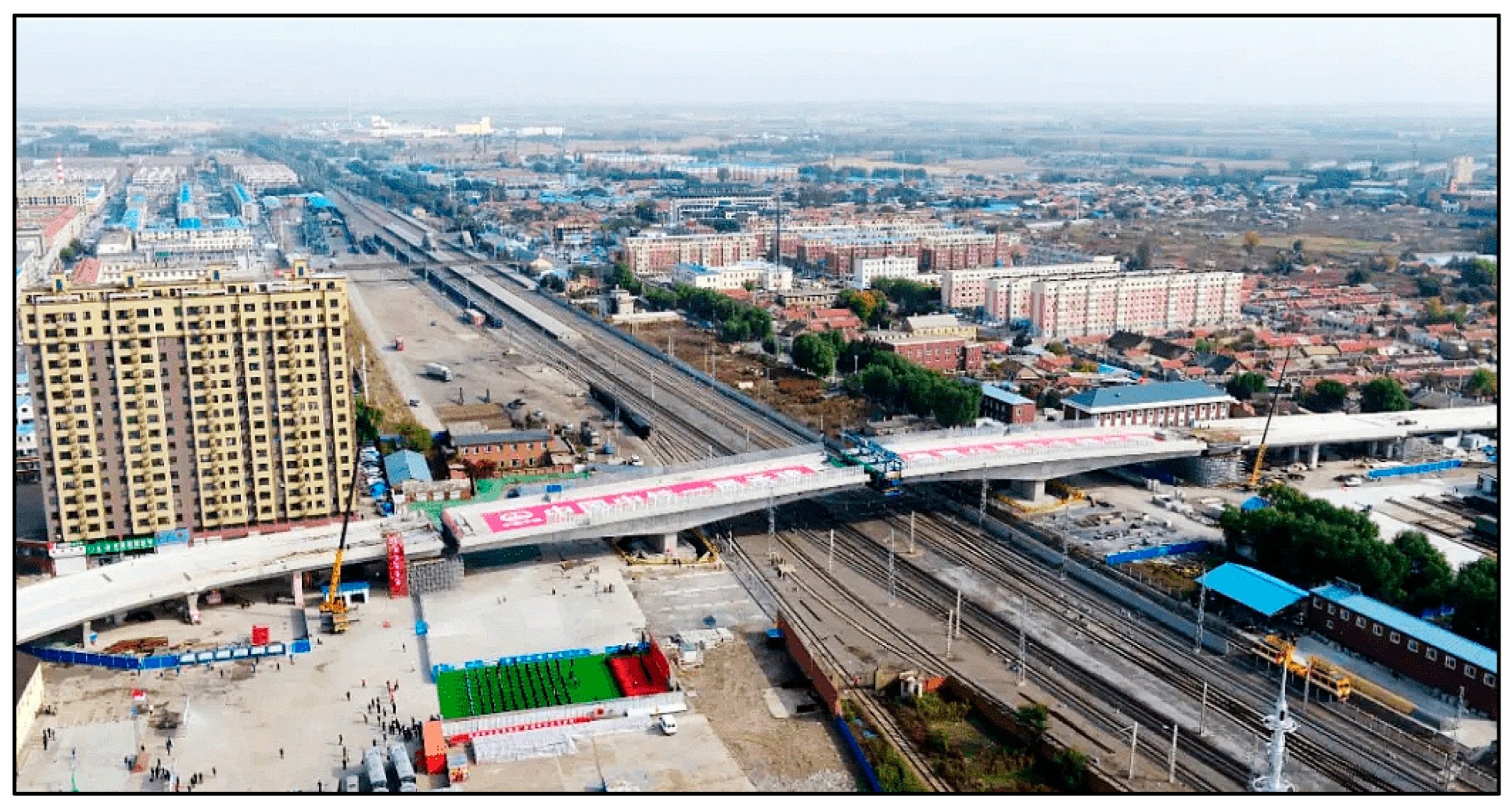
The project spans the throat area of Dehui Station, with a total length of 1140 m. As the bridge spans nine railway lines, including the main line of Beijing–Harbin Railway, construction is difficult. In view of the special working conditions of the adjacent existing railway line construction, in order to ensure the safety of the operating line and effectively control the structural deformation, the project innovatively adopts the horizontal rotation method construction technology to implement the cross-line operation. The main structure is designed as a three-span prestressed concrete continuous box girder system (span arrangement 60 + 100 + 60 m).
Figure 1 shows the actual layout of the bridge swivel construction site. The middle two joint positions are the swivel bridge cap parts. It can be seen that there are complex equipment installation and narrow construction space on the site, which provides a real basis for the implementation of subsequent temperature control measures.
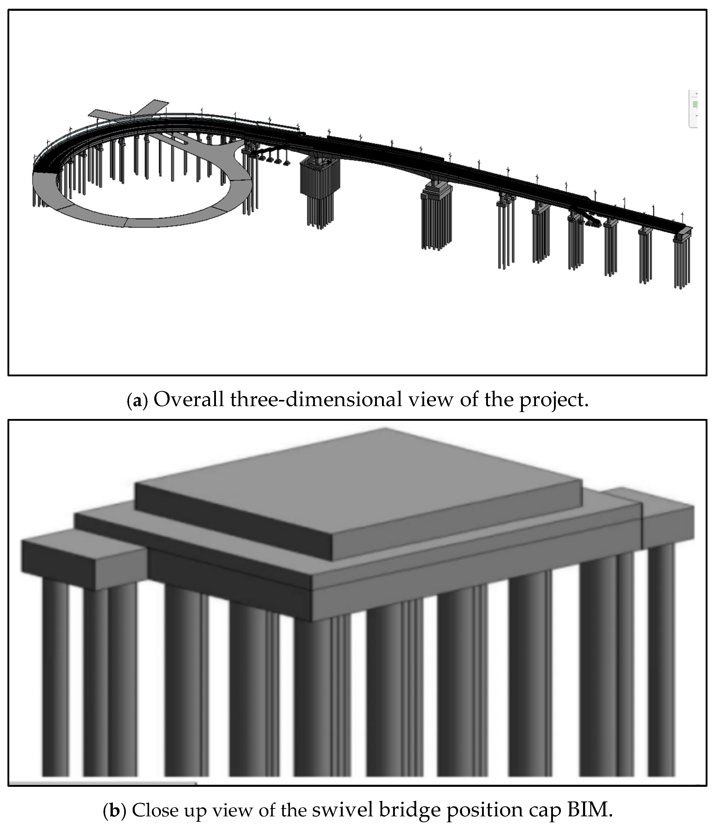
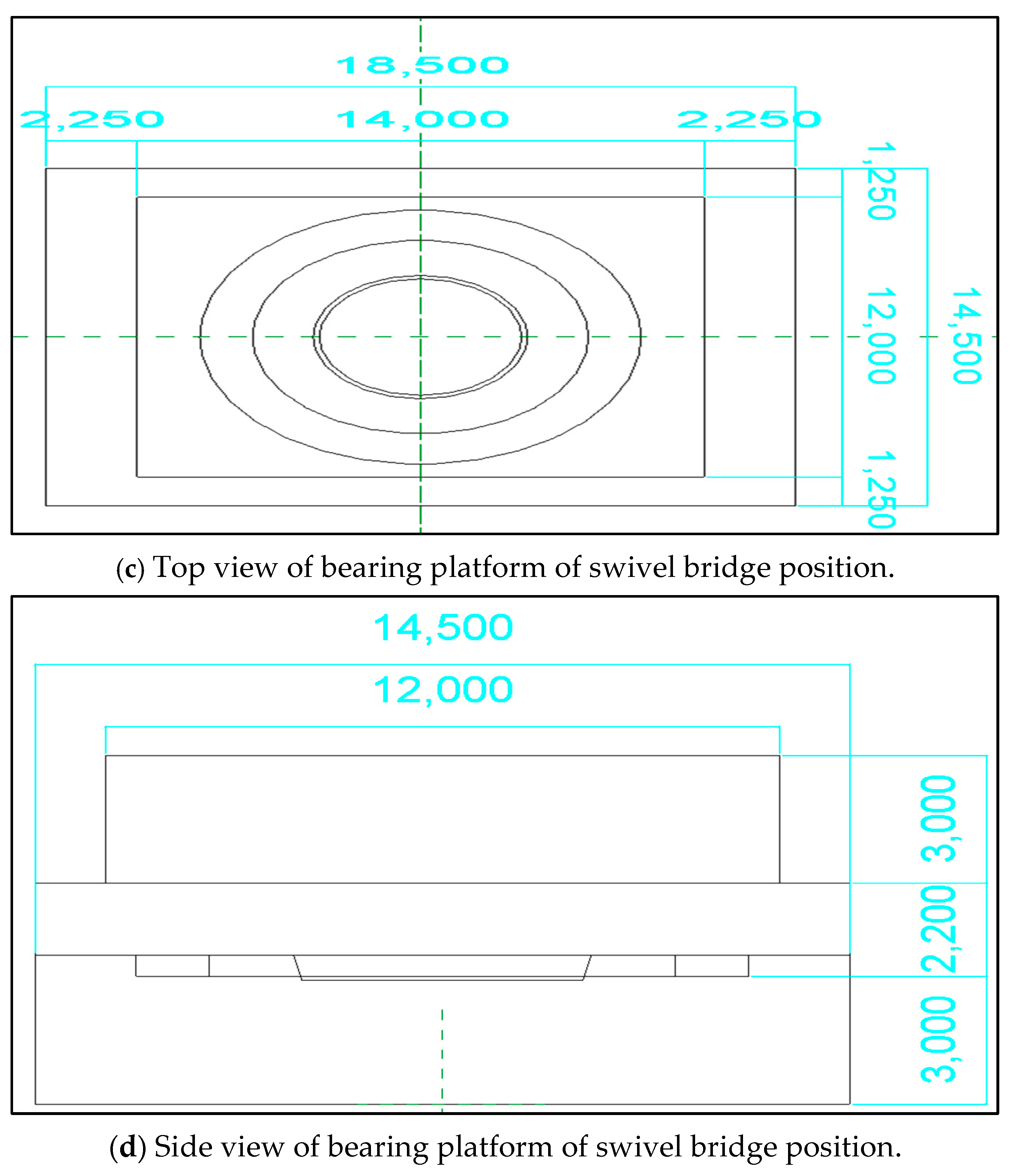
Taking No. 13 main pier as an example, its cap structure is divided into upper and lower parts. Specifically, the lower cap extends 14.5 m along the bridge direction, the lateral size is 18.5 m, and the overall height is 3.5 m. The upper cap is extended by 12 m along the bridge direction, with a lateral width of 14 m and a height of 3 m. As the volume of the upper cap is much smaller than that of the lower cap, this paper mainly analyzes the lower cap. In addition, considering that the lower pile cap area must reserve space for the installation of rotating system devices such as lower ball hinges and slideways, the actual height of the lower pile cap is determined to be 3 m, and C40 concrete grade is selected.
Temperature Control Requirements of Pile Cap
As the project is located in a cold area, the ambient temperature is low, and the weight of the swivel member is large, and given the specific position of the ball hinge, the traditional concrete curing method is difficult to implement. In order to achieve the goal of national high-quality engineering construction [
16], this project puts forward stricter control requirements for the temperature rise, inner surface temperature difference, and cooling rate of the cap [
17], and the detailed standards are shown in
Table 1.
Table 1 lists the national temperature control standard for mass concrete construction (GB 50496-2018) and the specific temperature control requirements of this project. As the aim of this project is the construction of the swivel bridge’s bearing platform, the overall requirements for the bearing platform will be very high. Stricter control standards are put forward for temperature rise and internal and external temperature difference (core temperature ≤ 40 °C, internal and external temperature difference ≤ 15 °C).
4. Pile Cap Mass Concrete Temperature Control
In this study, the hydration heat during the construction of the pile cap was simulated and analyzed by modifying the scheme of layered pouring, with or without a cooling water pipe and cooling water pipe arrangement. Under the premise of constant concrete material characteristics, initial temperature, time and boundary conditions, the layered pouring method was adopted, and the pouring height of each layer was 1.5 m.
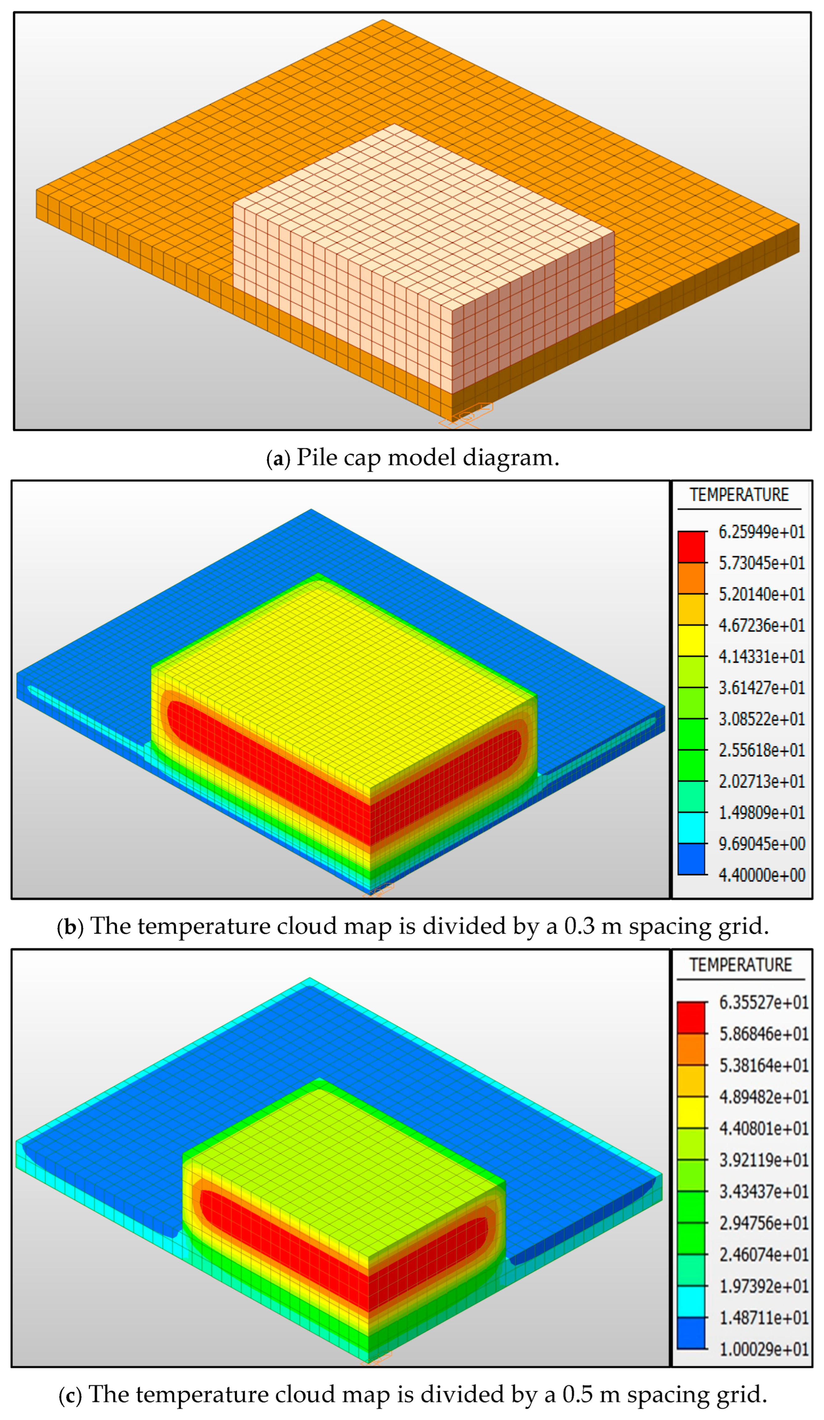
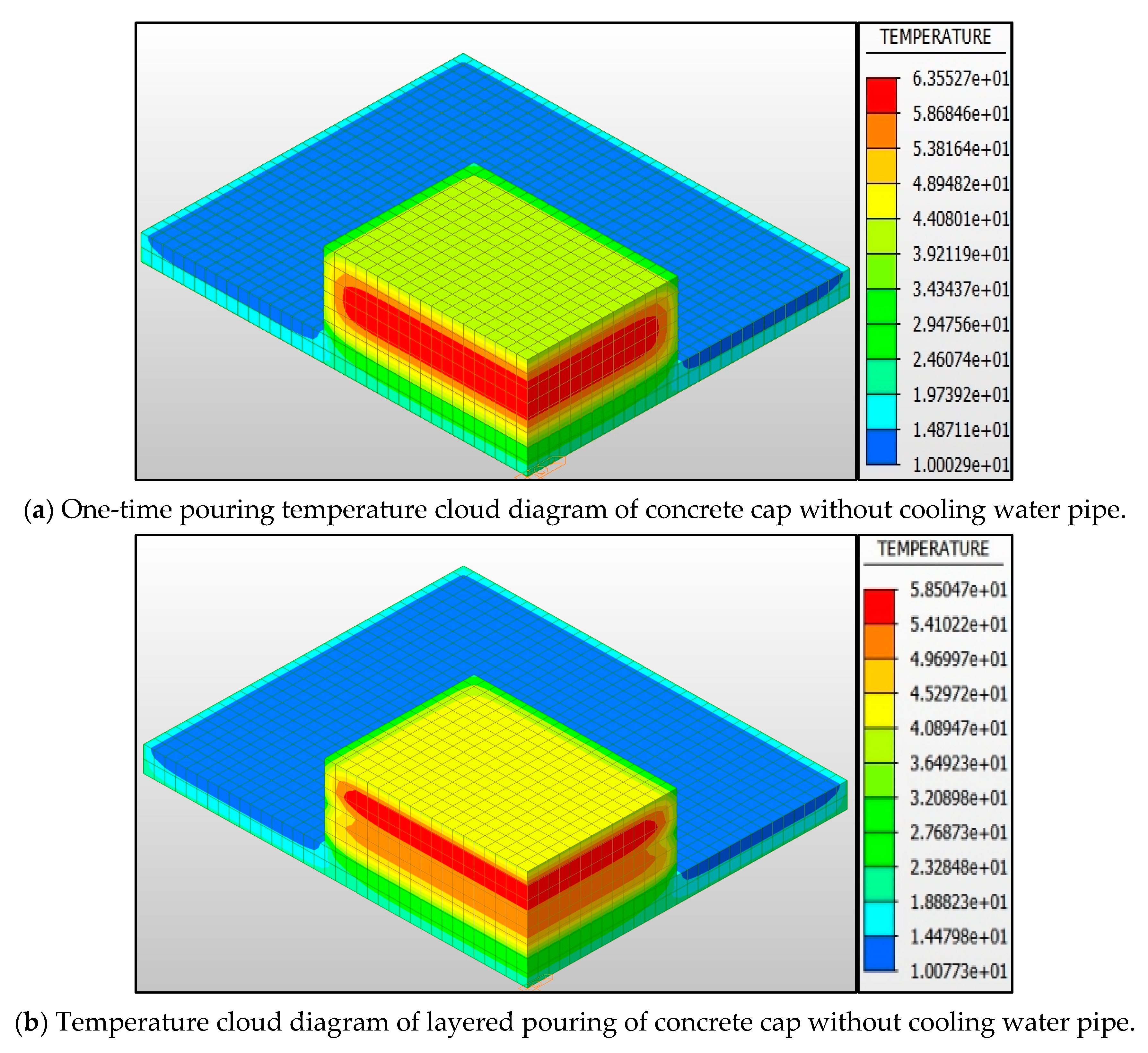
Figure 4a shows the temperature field distribution of mass concrete pile cap after 720 h of pouring.
Figure 4a shows the temperature cloud diagram of single pouring without a cooling water pipe. It can be seen that the temperature in the core area of concrete is concentrated, and the local maximum temperature reaches 63.55 °C.
Figure 4b shows the temperature field after the layered pouring method; the temperature distribution is more uniform, the high temperature zone shrinks, and the external temperature is significantly lower than the core area. It can be seen from
Figure 4a that the maximum temperature of concrete in single-layer pouring reaches 63.55 °C. This occurs under the condition of a pouring temperature of 10 °C, which exceeds the upper limit of temperature specified in ‘GB 50496-2018 Mass Concrete Construction Standard’ 3.0.4. After the layered pouring shown in
Figure 4b, the peak temperature is reduced to 58.50 °C, which meets the specified requirement of ≤50 °C. Therefore, the layered pouring method is selected to control the hydration heat [
22]. However, in order to make the project meet the ‘national quality project’ standard, the temperature rise still needs to be further controlled, keeping it within ≤40 °C.
In view of the pouring construction of mass concrete, the temperature and stress results under the above two working conditions will be compared and analyzed [
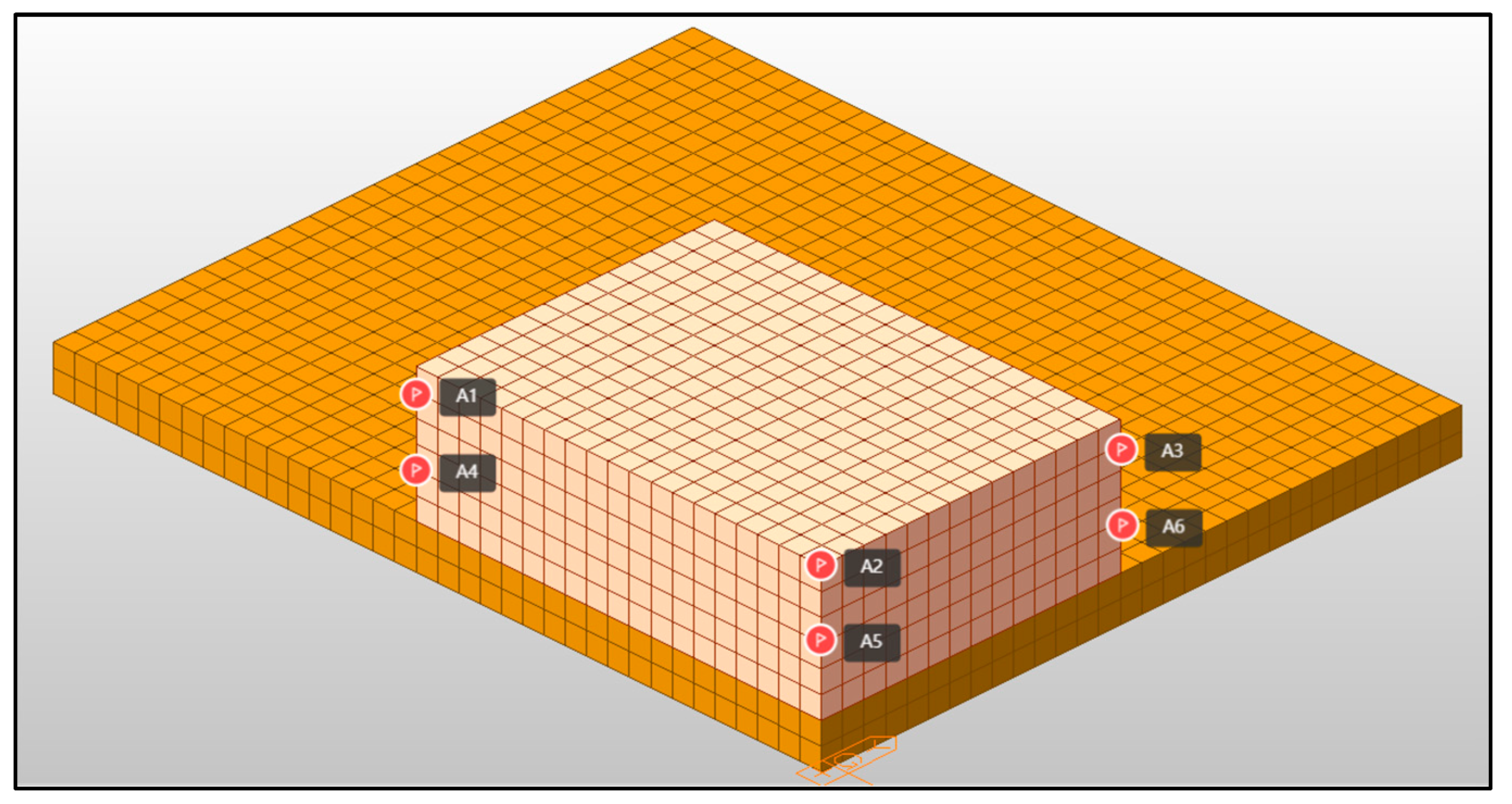
23]. To evaluate the influence of hydration heat more accurately, six representative measuring points of A1–A6 are selected for research, and the specific location is shown in
Figure 5. The measuring points A1 to A6 shown in
Figure 5 are distributed in the cap, in which A1 is located at the top, A5 is located in the central core area, and the remaining measuring points are arranged on the key section to fully reflect the temperature field distribution.
The position coordinates of A1–A6 measuring points are as follows:
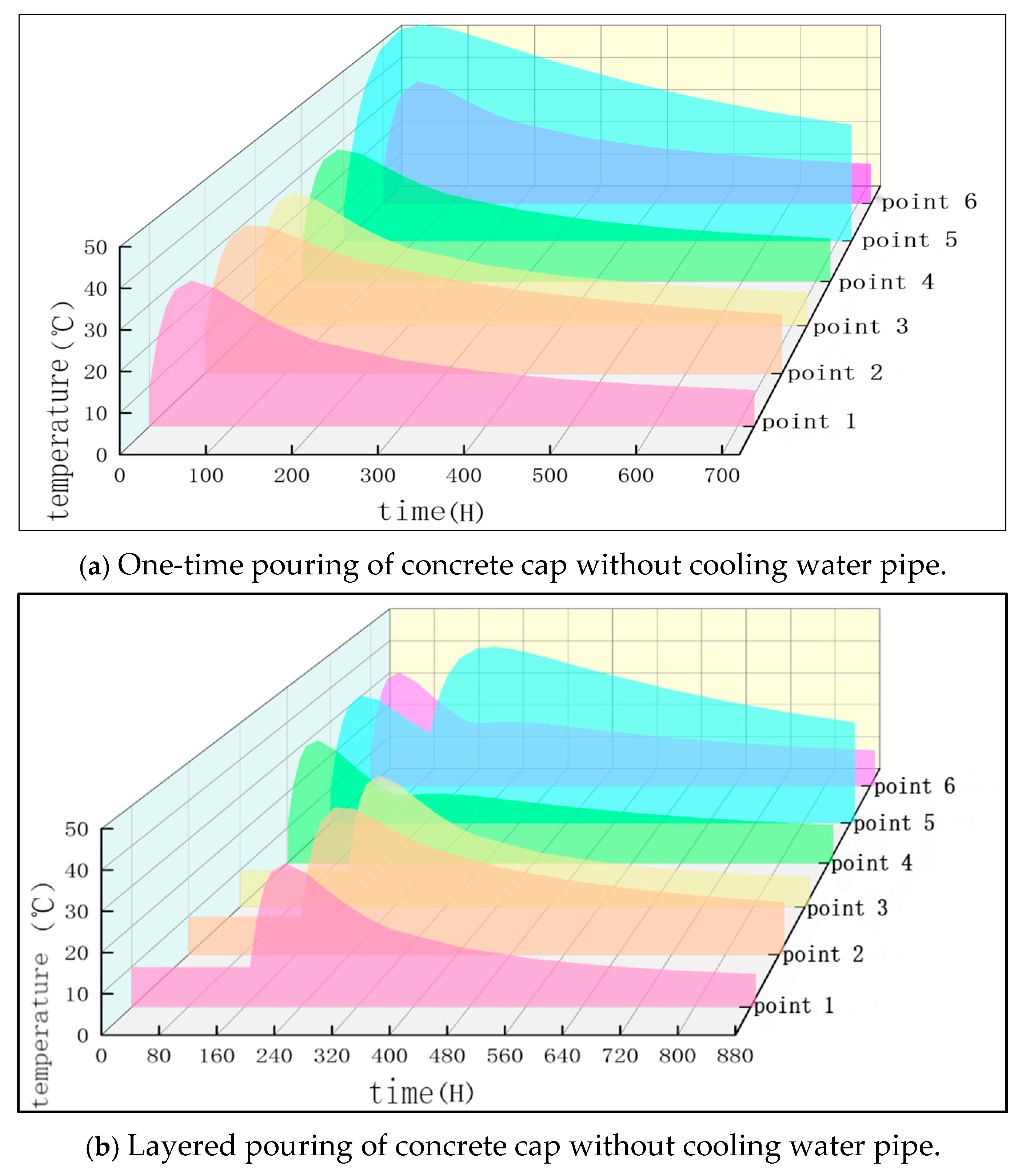
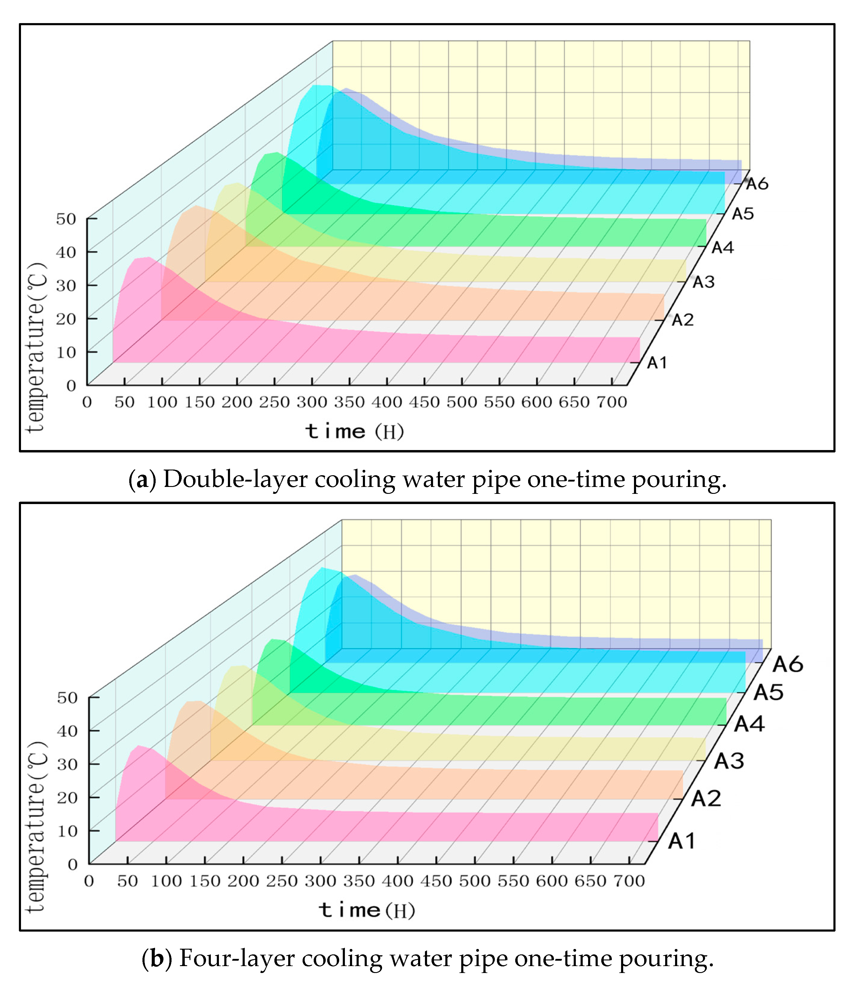
Figure 6 reveals the temperature evolution law of mass concrete pile cap under single pouring (
Figure 6a) and layered pouring conditions (
Figure 6b). Both of the two conditions show the three-stage characteristics of ‘rapid heating–peak platform–slow cooling’, but the temperature distribution and the degree of heat accumulation in the core area are significantly different. Specifically:
- (1)
During single pouring (
Figure 6a), the temperature of each measuring point rises rapidly within 50 h after pouring, and the peripheral measuring point reaches the peak at 50 h (such as the peak of measuring point 1–4 is about 55–58 °C), while measuring point 5 in the core area continues to heat up to 110 h due to the thermal inertia delay, reaching 63.55 °C (
Figure 6a) and exceeding the limit of 3.0.4 for “construction standard of mass concrete” (JGB 50496-2018), which states that the maximum temperature inside mass concrete should not exceed 60 °C. In addition, the heating rate (3.2 °C/h) and peak temperature of measuring point 5 are significantly higher than those of peripheral measuring points (1.8–2.1 °C/h), indicating that there is serious heat accumulation in the core area during single pouring.
- (2)
During layered pouring (
Figure 6b), the temperature curves of the first layer of concrete measuring points (4–6) are similar, with a peak of about 45 °C (168 h). However, the temperature of measuring point 5 in the core area after the second layer of pouring continues to rise, reaching a peak of 52.11 °C at 278 h. Although it is lower than the single pouring peak, it is still higher than other measuring points in the same period (peak of about 40 °C, 218 h). In the cooling stage (278–888 h), the temperature drop at measuring point 5 lags significantly, and its temperature (30 °C) at 888 h is about 3 times that of the peripheral measuring point (10 °C), indicating that although layered pouring can reduce the temperature difference between the core area and the periphery (the maximum temperature difference of single pouring is 28.5 °C vs. layered pouring 20.1 °C), it is still difficult to completely control the temperature rise of the core area by relying solely on the layered process (
Figure 6b).
It can be seen from
Figure 6a,b that layered pouring can effectively optimize the uniformity of temperature distribution, the peak temperature in the core area is 18.1% lower than that of single pouring, and the temperature gradient is reduced by 32% (single pouring gradient 1.8 °C/cm vs. layered pouring 1.2 °C/cm), which meets the requirements of
Section 3.1 of the specification that the temperature gradient should not be greater than 1.5 °C/cm. However, the thermal delay effect in the core region exists in both conditions, which needs to be supplemented by a cooling system or an extended temperature control cycle (e.g., the cooling rate in the core region is only 0.03 °C/h during layered pouring, and additional intervention is required). The research results emphasize that layered pouring combined with active temperature control measures should be given priority in the construction of thick and large concrete structures to simultaneously meet the dual requirements of the specification for temperature rise limit and temperature gradient.
This study is based on the material properties of C40 concrete, and its 28-day tensile strength standard value is 2.39 MPa (according to GB50010-2010 [
24]). Considering the temporary load combination coefficient 1.6 and the material partial coefficient 1.45 during the construction period, the basic allowable tensile stress σ
allow = 2.39/(1.45 × 1.6) = 1.65 MPa is calculated. For the single pouring condition, the early strength reduction coefficient is superimposed to be 0.62 (3d strength development), and the final allowable value is corrected to be 2.64 MPa. Due to the interface effect of construction joints, the interface strength reduction factor of 0.63 is adopted in the layered pouring condition, and the allowable value is adjusted to 1.66 MPa.
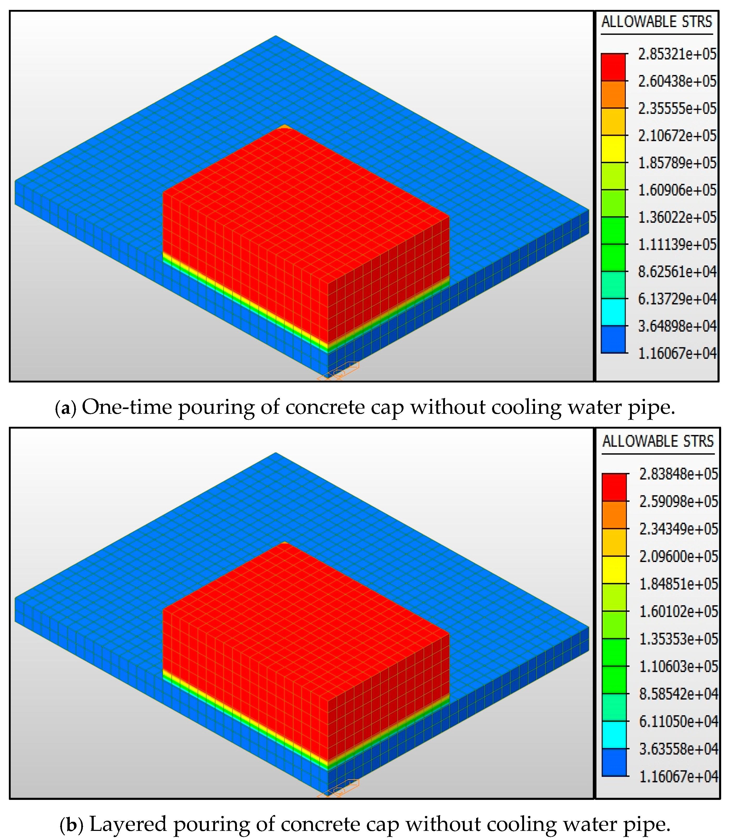
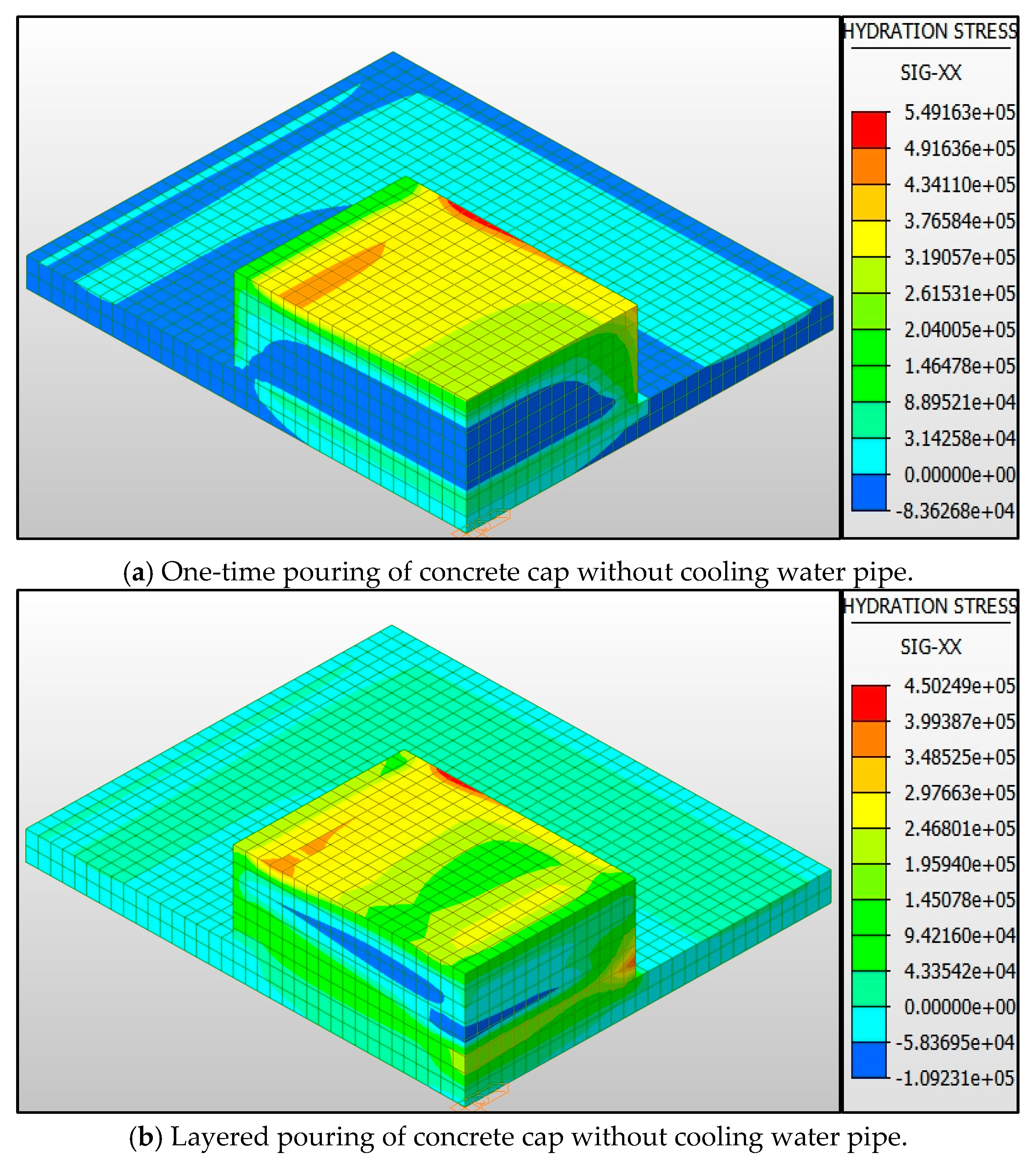
By comparing the stress distribution characteristics of the contour map in
Figure 7, it can be found that, in the single pouring condition (
Figure 7a), the maximum allowable tensile stress of the concrete cover plate is 2.85 MPa, and the high stress area is elliptically concentrated in the central area of the structure. The stress gradient obviously changes, and the contour line begins to be dense at the 1/4 span from the edge; the maximum allowable tensile stress of the layered pouring condition (
Figure 7b) is 2.83 MPa, and the stress distribution presents a dual-core feature. The high stress zone shifts to both sides by about 15%. The isoline spacing is more uniform than that of a single pouring, and the stress concentration phenomenon is alleviated.
By analyzing the time-history stress cloud diagram in
Figure 8, it can be seen that the maximum tensile stress of the single pouring condition (
Figure 8a) under the action of concrete hydration heat is 5.49 MPa, which exceeds the allowable value of 2.64 MPa by 92.47%. At this time, the stress contour diffuses around in a concentric circle, forming a dark high stress core with a diameter of about 2 m in the center of the structure, and the distance between the contour lines in the edge area is significantly larger than that in the center area. Compared with the layered pouring condition (
Figure 8b), the maximum stress value is reduced to 4.50 MPa, but the allowable value of 1.66 MPa is still exceeded by 58.62%. It is worth noting that the stress distribution after layered pouring shows layered characteristics, and the contour line shows an obvious turning point at the construction joint. The area of high stress area is about 40% less than that of single pouring, and the maximum stress point shifts to the surface layer by 0.5–0.8 m. This shows that the layered pouring can effectively reduce the stress concentration in the core area by changing the temperature gradient distribution so that the equivalent stress distribution tends to be uniform.
In terms of controlling the peak temperature and stress of the concrete of the pile cap and reducing the temperature gradient, the layered pouring has more advantages than the one-time pouring, which can reduce the risk of cracks caused by the temperature stress. However, whether it is in terms of temperature or stress, it is still impossible to achieve the goal of the specification and the ‘national high-quality project’ by relying solely on the layered technology. Therefore, it is necessary to introduce the cooling water pipe [
25] device to control and analyze the concrete temperature.
4.1. Design and Research of Cooling Water Pipe Device
How to accurately consider the cooling effect of water pipes is still a key issue in the simulation analysis of temperature control of mass concrete caps [
26]. The convective heat transfer coefficient of the cooling water pipe directly affects the accuracy of the calculation results, which reflects the heat exchange capacity between the concrete and the cooling water. In order to improve the accuracy of numerical calculation, this paper adopts the calculation model proposed in Reference [
27], which can evaluate the convective heat transfer coefficient of cooling water pipe more comprehensively. This method not only considers the flow rate of cooling water, but also combines the material characteristics of the cooling water pipe and the influence of geometric parameters (such as pipe diameter, wall thickness, etc.) on the heat transfer process. Based on the law of conservation of energy and the theory of forced convection heat transfer [
28], the formula for calculating the convective heat transfer coefficient of the cooling water pipe is derived as follows [
29].
In the formula above, and are the outer radius and inner radius of the pipe, respectively; is the thermal conductivity of the cooling water pipe; u is the flow rate; is the ratio of the outer diameter to the inner diameter of the cooling water pipe; and is an adjustment coefficient related to the material and geometric size of the cooling water pipe.
The amount of heat dissipation is also a very important index that can reflect the degree of temperature control of the cooling device. The calculation formula of the heat dissipation of the cooling water pipe is:
In Formula (8), Q represents the heat dissipation of the cooling water pipe per unit time; h represents the convective heat transfer coefficient of the cooling water pipe; A represents the surface area of the cooling water pipe; and ΔT is the temperature difference between the outlet of the cooling water pipe and the inlet water temperature.
4.1.1. Study of the Diameter of Cooling Water Pipe
When studying the influence of different parameters of cooling water pipe on hydration heat, the pouring method of the concrete cap is controlled to be the same; these are all the case in one-time pouring.
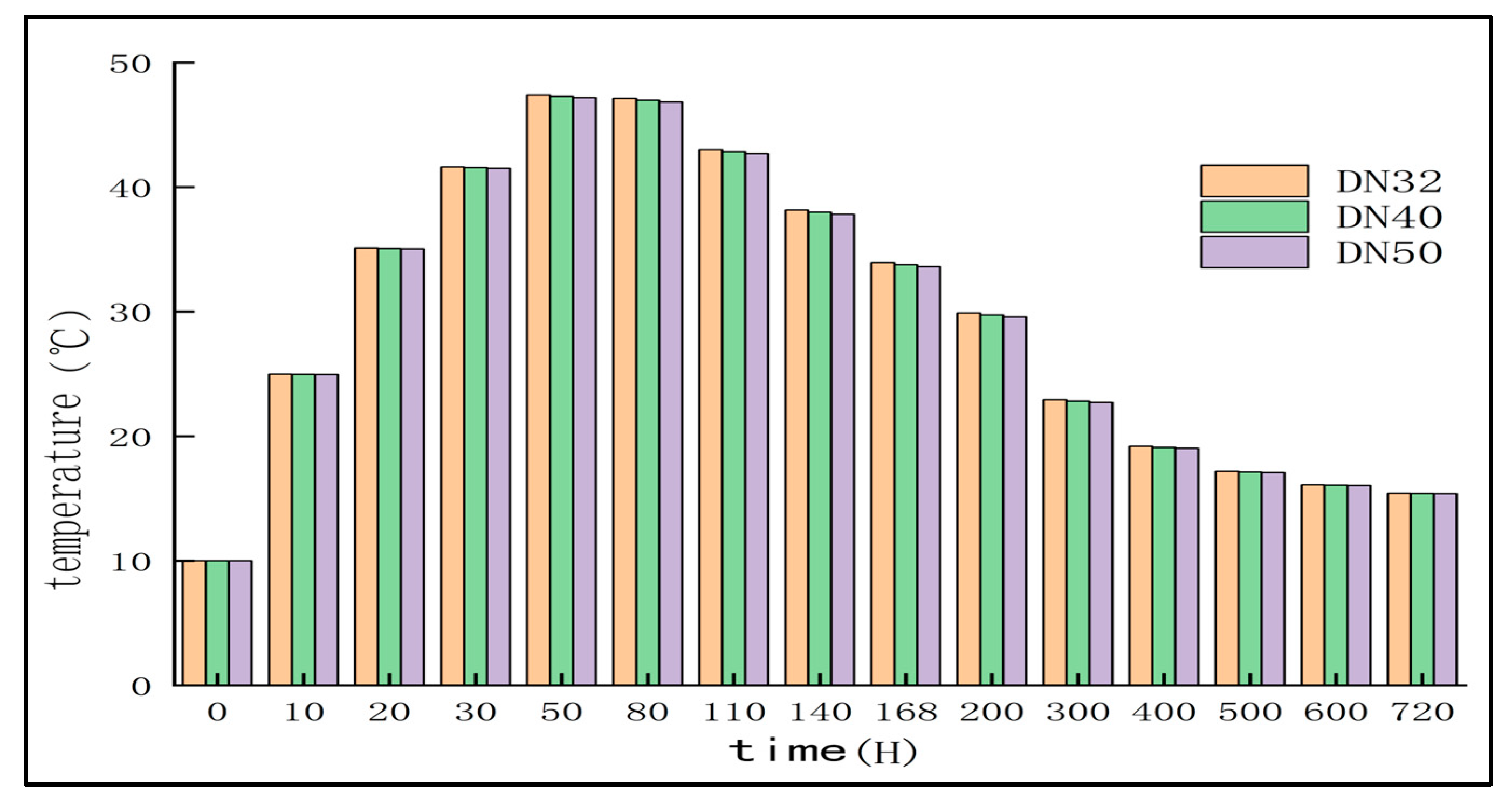
Select the measuring point A5 [
30] as the analysis point. The cooling water inflow temperature is set to 15 °C [
31], the flow rate is set to 1.2 m
3/h, and the diameter of the cooling water pipe is set to DN32, DN40, and DN50; the convection coefficient corresponding to different pipe diameters is shown in
Table 3. Bring this coefficient into the finite element software Midas Civil for simulation and obtain the temperature change diagram of the measuring point A5 under different pipe diameters, as shown in
Figure 9.
The bar chart of
Figure 9 shows that, when all conditions other than the diameter of the cooling water pipe are the same, the following phenomenon becomes visible: the larger the diameter of the cooling water pipe, the lower the hydration heat temperature of the concrete at the A5 measuring point. The three diameter cooling water pipes all reached the highest temperature after 50 h. At this time point, the peak hydration heat temperature of the DN50 cooling water pipe only decreased by 1.19% compared with that of DN25 cooling water pipe. With the passage of time, the cooling water pipes of DN25, DN40, and DN50 had little difference in cooling speed.
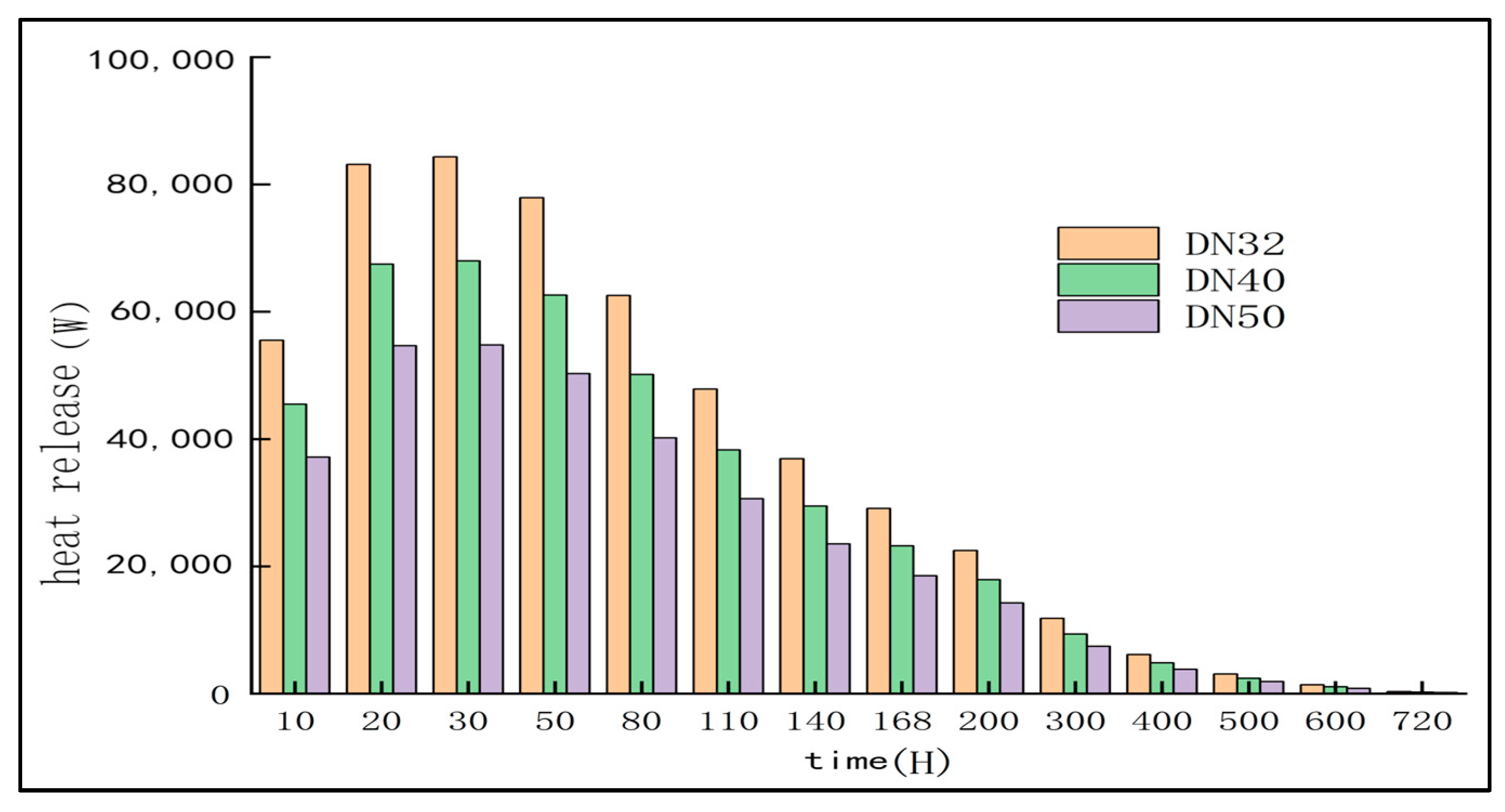
The heat dissipation of the cooling water pipe device with three different pipe diameters is compared. It can be seen from
Table 4 and
Figure 10 that the heat dissipation is large in DN32. The temperature comparison shows that the larger the pipe diameter is, the better the temperature control effect is, but the change of the pipe diameter is not particularly obvious for the concrete cooling effect. Therefore, it is not necessary to excessively pursue the increase of the pipe diameter of the cooling water pipe. Considering the cost-effectiveness, it is more appropriate to choose the DN40 cooling water pipe.
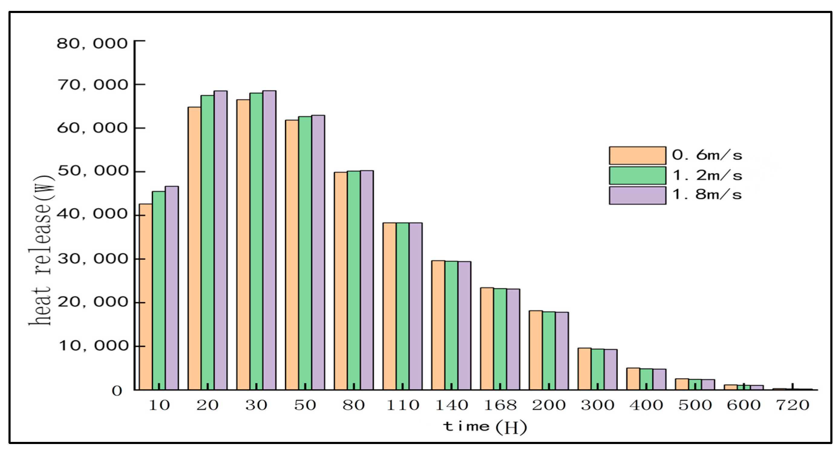
4.1.2. Study on the Flow Velocity of Cooling Water Pipe
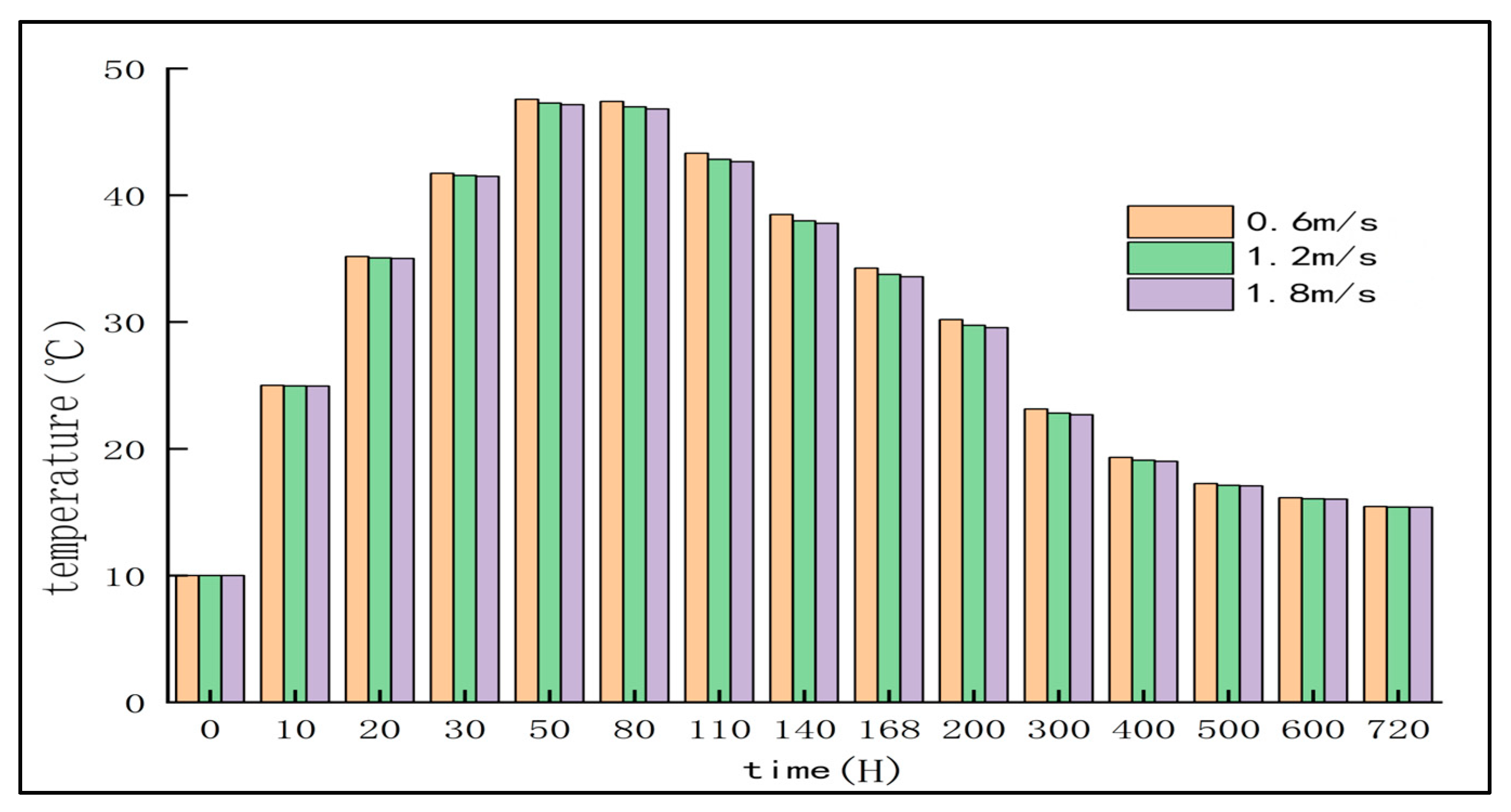
In order to study the influence of different water flow rates on the temperature distribution of the pile cap when the cooling water pipe is flowing through the water under the premise that other conditions remain unchanged, three flow rates of 0.6 m/s, 1.2 m/s and 1.8 m/s were selected, and the corresponding convective heat transfer coefficients were calculated (see
Table 5) [
32]. These parameters are substituted into the finite element software for calculation, and the temperature change curve of A5 measuring point under different flow velocity conditions is obtained by simulation (as shown in
Figure 11).
The simulation results show that the influence of adjusting the flow rate of cooling water on the hydration heat temperature of concrete is limited. From the perspective of cost-effectiveness, the economic benefit of increasing the flow rate is not obvious. When the flow rate increased from 0.6 m/s to 1.8 m/s, the peak value of hydration heat temperature decreased only by 0.89%.
The heat dissipation of the cooling water pipe device with three different flow rates is compared. It can be seen from
Table 6 and
Figure 12 that the heat dissipation of the cooling water pipe device can be changed by changing the cooling water flow rate in the first 80 h, and the maximum increase rate of the heat dissipation is 9.55%. However, the heat dissipation changes little by changing the cooling water flow rate within 80–720 h. At the same time, the overall heat dissipation trend is similar under the three cooling water flow rates. Therefore, it is not necessary to excessively pursue the increase of water flow rate, and the flow rate of about 1.2 m/s is enough to meet the demand.
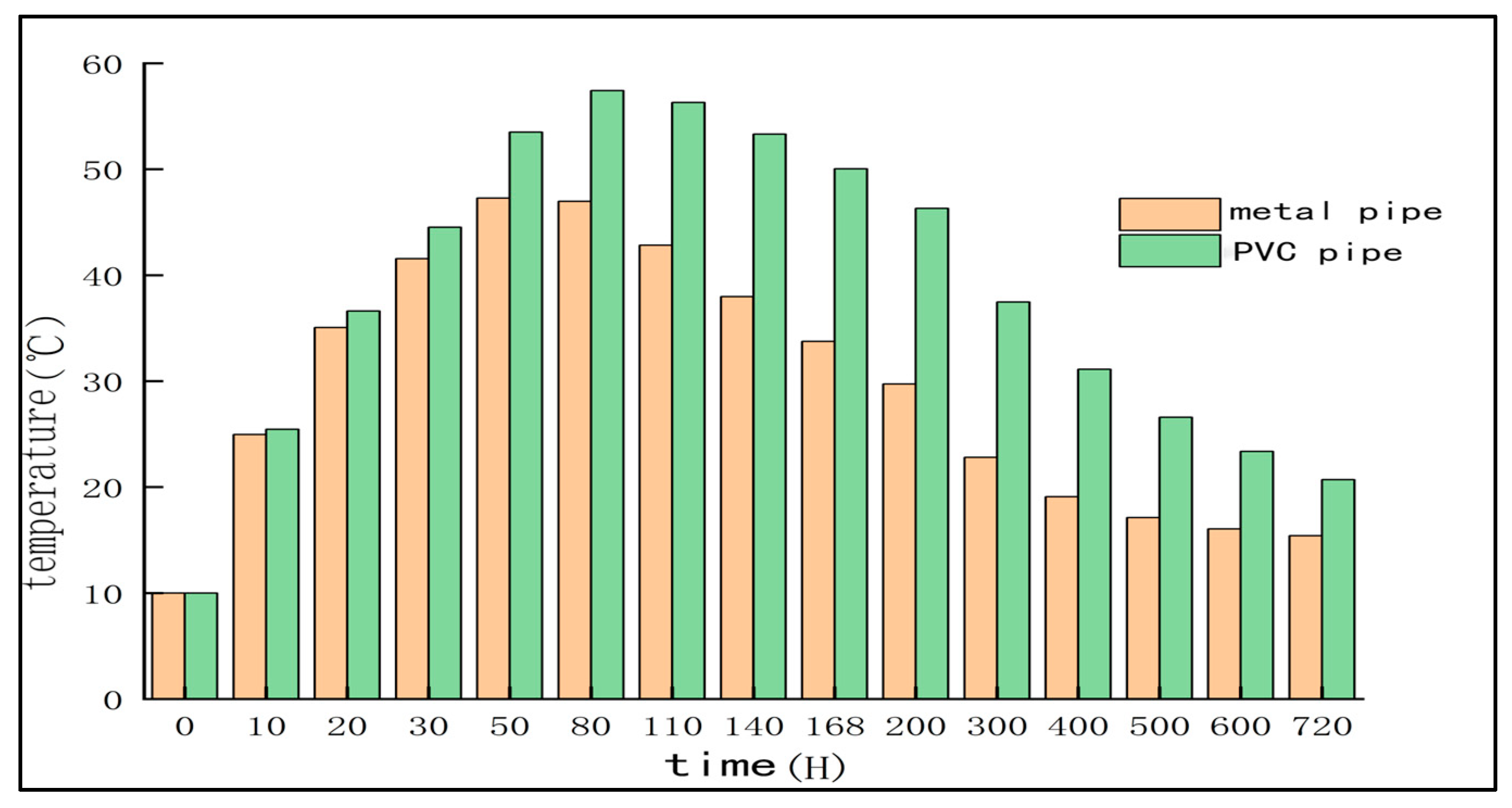
4.1.3. Study on the Material of Cooling Water Pipe
The point A5 was selected to change the material of the cooling water pipe while maintaining the type and flow rate of the cooling water pipe to be DN40 and 1.2 m/s, respectively. The metal water pipe and PVC water pipe were selected for comparison. The parameters of the two pipes are shown in
Table 7, and the temperature change diagram is shown in
Figure 13.
The bar chart of
Figure 13 shows that the metal water pipe shows a better cooling effect when compared to the PVC water pipe. This may be because the thermal insulation performance of the metal water pipe is relatively weak, which promotes heat exchange with the concrete. The temperature of concrete using the metal water pipe peaked at 50 h, while the temperature of concrete using the PVC water pipe was still rising and peaked at 80 h. Specifically, the maximum temperature of the pile cap with metal water pipe at the A5 measuring point is 47.27 °C, while that of the PVC water pipe is 57.42 °C, and the temperature peak of the metal water pipe is 10.15 °C lower than that of the PVC water pipe.
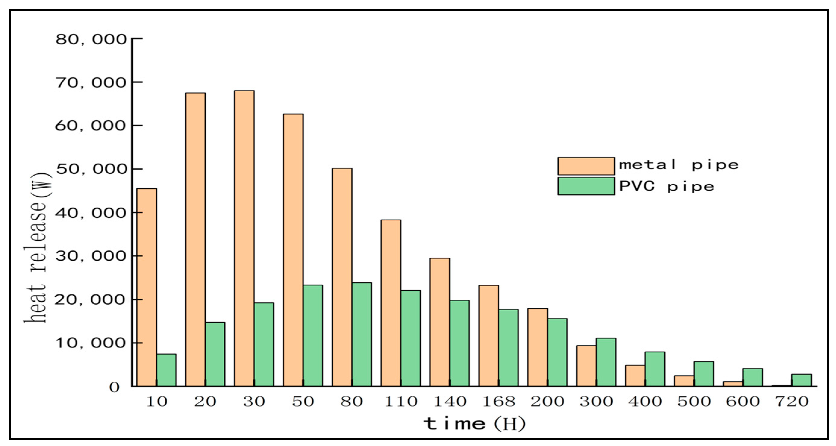
By comparing the heat dissipation of cooling water pipes with different materials as shown in
Table 8 and
Figure 14, it can be seen that, within 720 h, the heat dissipation of metal water pipes first increases and then decreases, which is in line with the trend of concrete hydration heat. At the same time, the heat dissipation of the metal pipe device has always been higher than that of the PVC pipe device within 200 h. Within 300–720 h, the heat dissipation of the metal pipe is less than that of the PVC pipe. This occurs because the hydration heat reaction of the concrete of the pile cap has been controlled by the metal pipe device during this period, so the temperature difference between the inlet and outlet of the water pipe device is small, while the PVC pipe has increased for up to 720 h. The temperature of the concrete pile cap cannot be stably controlled. Because the thermal conductivity of the metal tube is significantly higher than that of the PVC tube, the metal tube can transfer the heat inside the concrete more quickly, thus showing a better cooling effect. It can be seen that metal water pipe is more suitable than a PVC water pipe.
In addition to technical performance, we also compared the performance of metal pipes and PVC pipes in terms of economy and environmental impact. Although the initial cost of PVC pipe is low, it has disadvantages in long-term durability and maintenance, and its manufacturing and disposal process may bring greater environmental pollution. On the contrary, although the purchase cost of metal pipe is slightly higher, it has longer service life and lower maintenance cost, which meets the requirements of mass concrete engineering in severe cold areas. Therefore, it is more reasonable to choose metal pipes in this scheme.
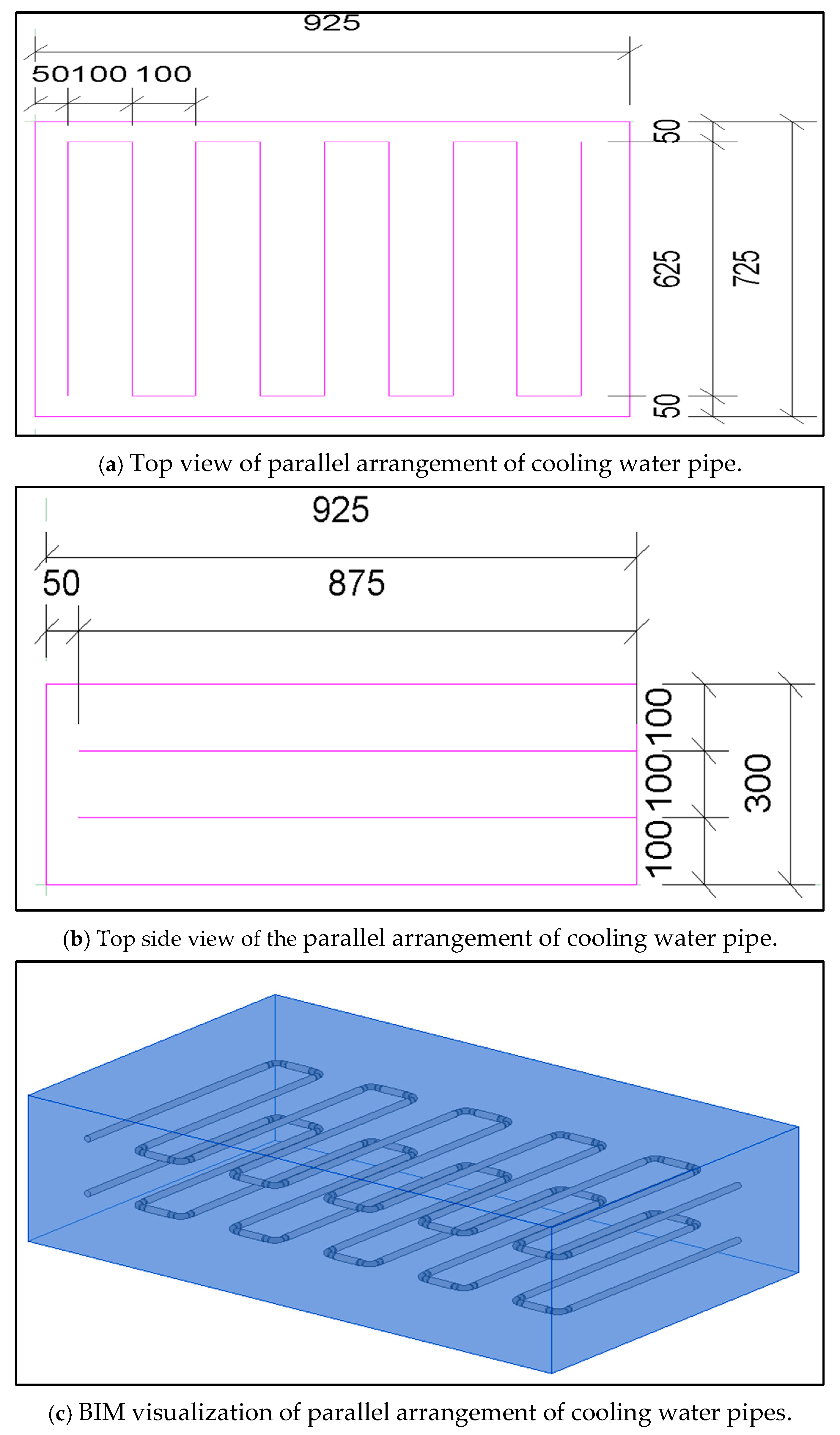
4.1.4. Study on the Arrangement of Cooling Water Pipe
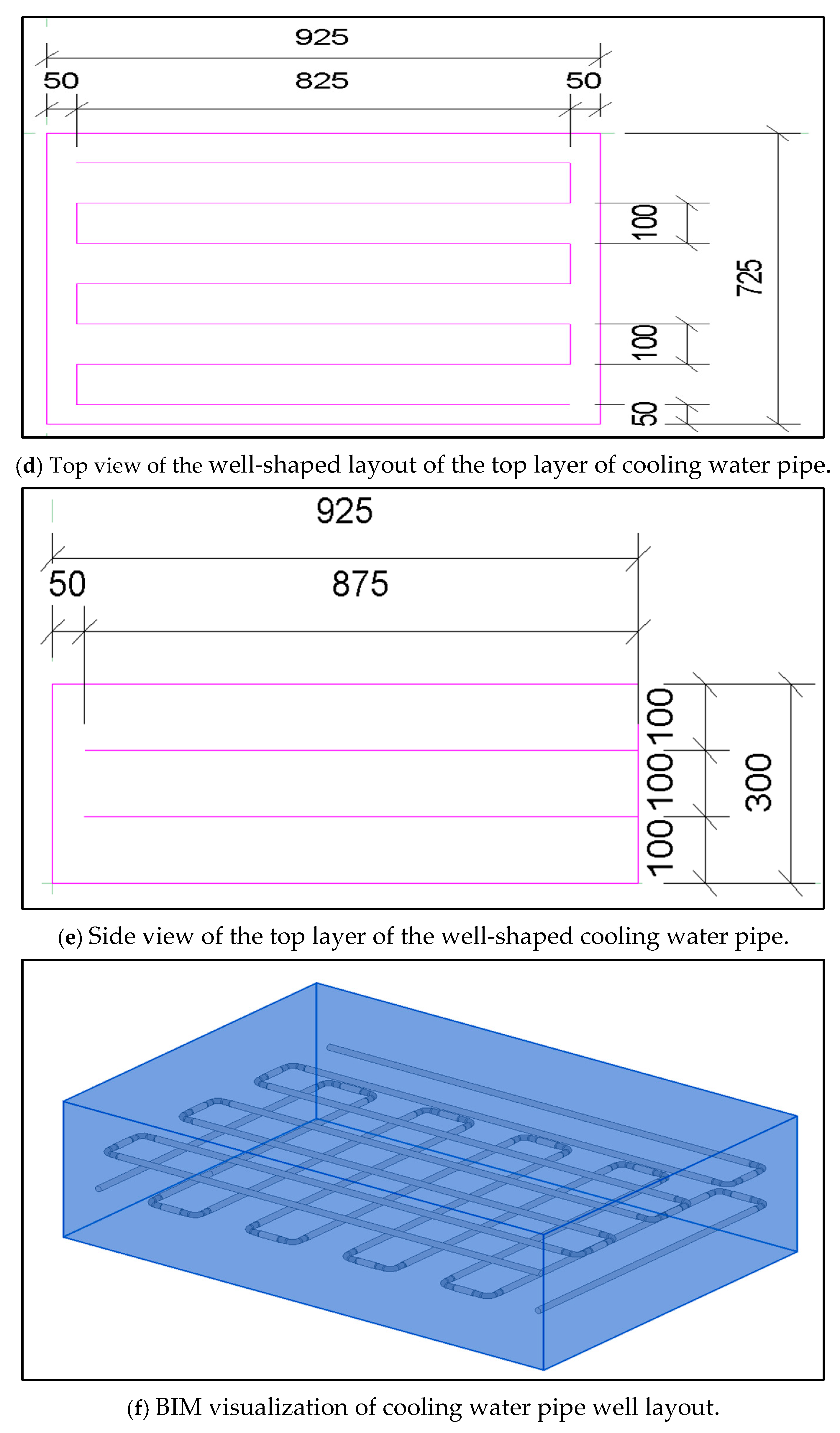
There are usually two ways to bury the traditional concrete cooling water pipe: ring and snake. In this paper, the serpentine layout is selected, and the serpentine layout is divided into parallel layout and well-shaped layout (see
Figure 15) [
33]. As shown in the
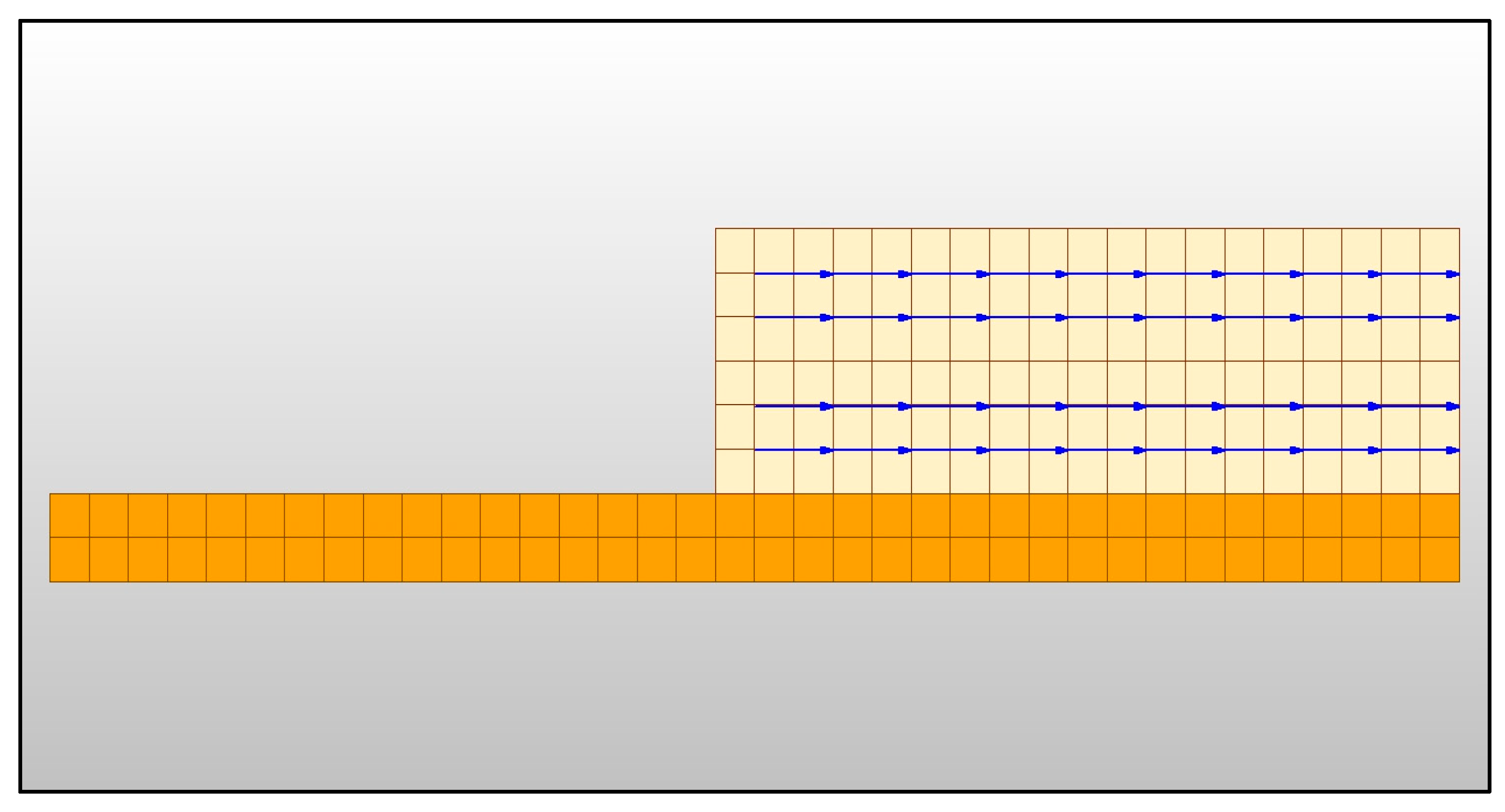
Figure 15, for the parallel arrangement of cooling water pipes, the requirement is that the upper water pipe is 1 m from the top of the concrete, and the lower layer is 1 m from the upper edge of the foundation, and the distance between the two is 1 m. The horizontal spacing is 1 m, and the two sides are 0.5 m away from the concrete edge. The water pipe is arranged vertically, and the single pipe is 6.25 m long. For the arrangement of well-shaped cooling water pipes, the spacing between the upper and lower layers and the arrangement of the lower water pipes require parallel arrangement to be consistent. The upper water pipes are arranged horizontally. The length of a single pipe is 8.25 m, the spacing between the two water pipes is 1 m, and the distance between the two sides is 0.5 m from the outer edge of the concrete.
Under the conditions of fixed water pipe model DN40, flow rate 1.2 m/s, water inlet temperature 15 °C, and metal material, the analysis is carried out by changing the layout of the cooling water pipe (as shown in
Figure 16).
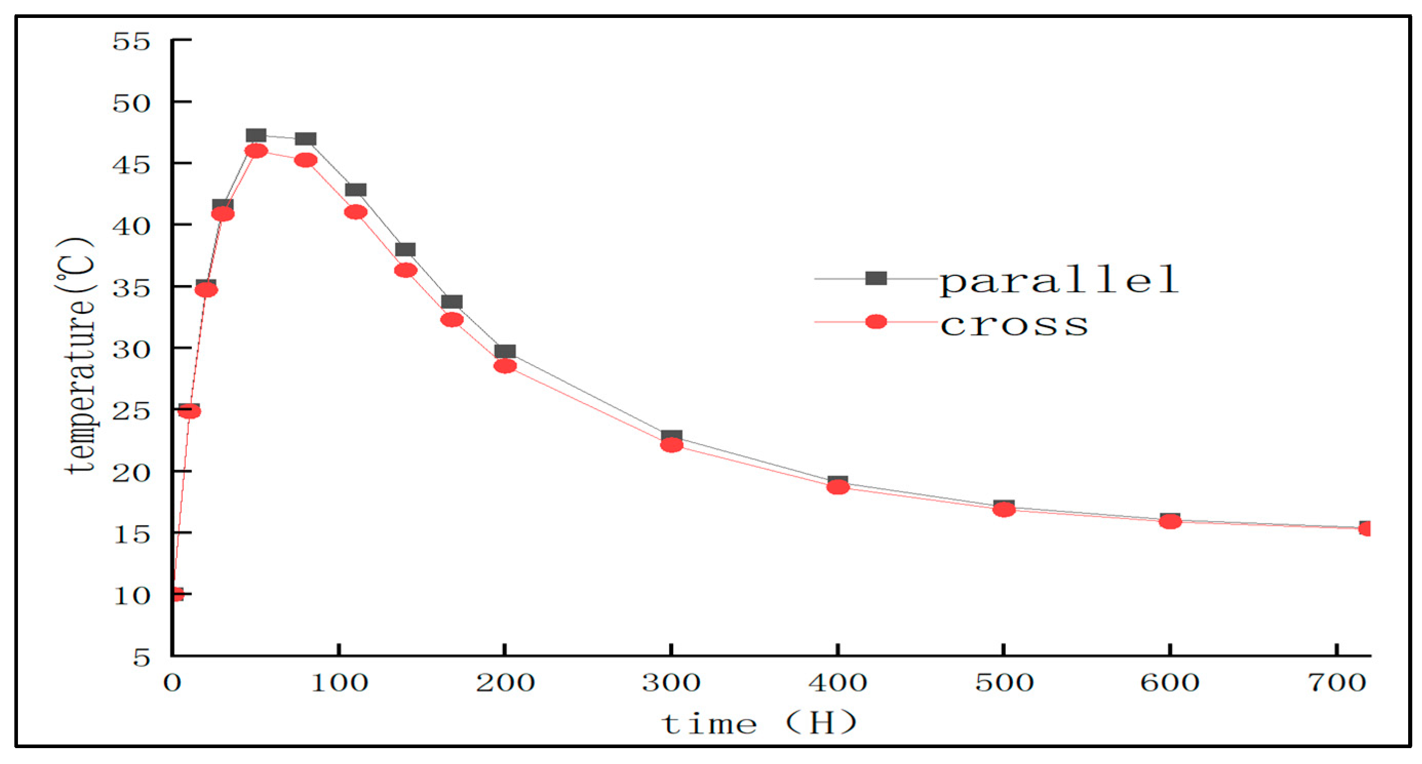
The finite element simulation results show that the hydration heat of mass concrete at the A5 measuring point reaches the peak value 50 h after the water is passed, and the temperature change values under different arrangement modes are almost the same, indicating that at this stage, the two arrangement modes have the same control effect on the hydration heat temperature. In this stage, the maximum temperature of the parallel arrangement of A5 measuring points is 47.2 °C, and the maximum temperature of the well-shaped arrangement is 46.01 °C. The temperature is reduced by 1.25 °C, which is reduced by 2.6%.
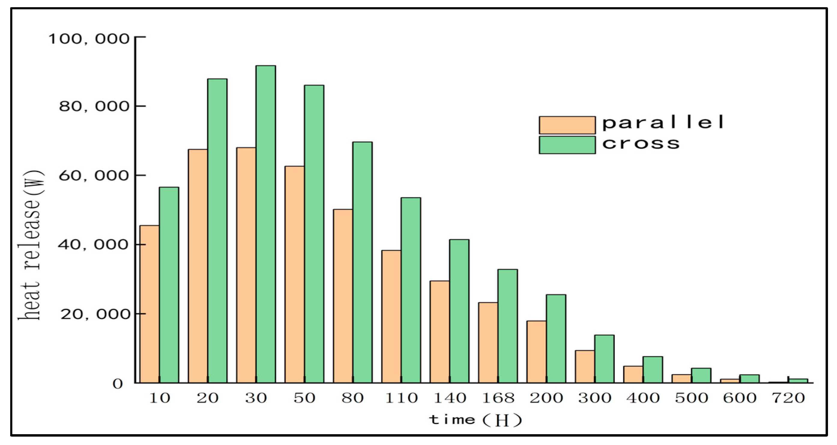
By comparing the heat dissipation of different arrangement devices, as shown in
Figure 17, it can be seen that the heat dissipation of the well-shaped arrangement device has always been higher than that of the parallel arrangement device, especially in the early stage. The effect is more obvious, but the temperature control effect reflected in the temperature angle is not much different from that of the parallel arrangement. Although the two arrangements are geometrically different, the heat dissipation results are similar because they both fully cover the key areas inside the concrete, and the fluid state is basically the same. In general, the parallel arrangement and the well-shaped arrangement cooling water pipe have little effect on the hydration heat of concrete. Considering the difficulty of on-site construction and construction cost, the parallel arrangement cooling water pipe device is selected.
According to the above comparative experiments, the final choice of cooling water pipe parameters for the water pipe model DN40, flow rate 1.2 m/s, the inflow temperature is 15 °C, and the material is the metal water pipe with parallel arrangement. The specific plan is as follows.
After determining the above parameters, we designed four schemes to carry out the concrete pile cap. In Scheme 1 (see
Figure 15a,b and
Figure 18), a one-time pouring of 3 m thick concrete is adopted. The requirement is that the upper water pipe is 1 m from the top of the concrete, the lower layer is 1 m from the upper edge of the foundation, and the distance between the two is 1 m. The horizontal spacing is 1 m, and the two sides are 0.5 m away from the edge of the concrete. The water pipe is arranged vertically, and the length of the single pipe is 6.25 m.
Scheme 2 (see
Figure 15a and
Figure 19) also adopts one-time pouring of 3 m thick concrete, but four layers of cooling water pipes are arranged inside; the upper water pipe is 0.5 m from the top of the cap [
34], the lower water pipe is 0.5 m from the top of the foundation, and the middle two layers of water pipes are separated by 1 m [
35].
Schemes 3 and 4: Layered pouring scheme.
Corresponding to the two-layer and four-layer cooling water pipe layout, the thickness of each layer is 1.5 m, and the internal water pipe layout is set according to the position in Scheme 1 or Scheme 2.
4.2. Temperature Field Analysis
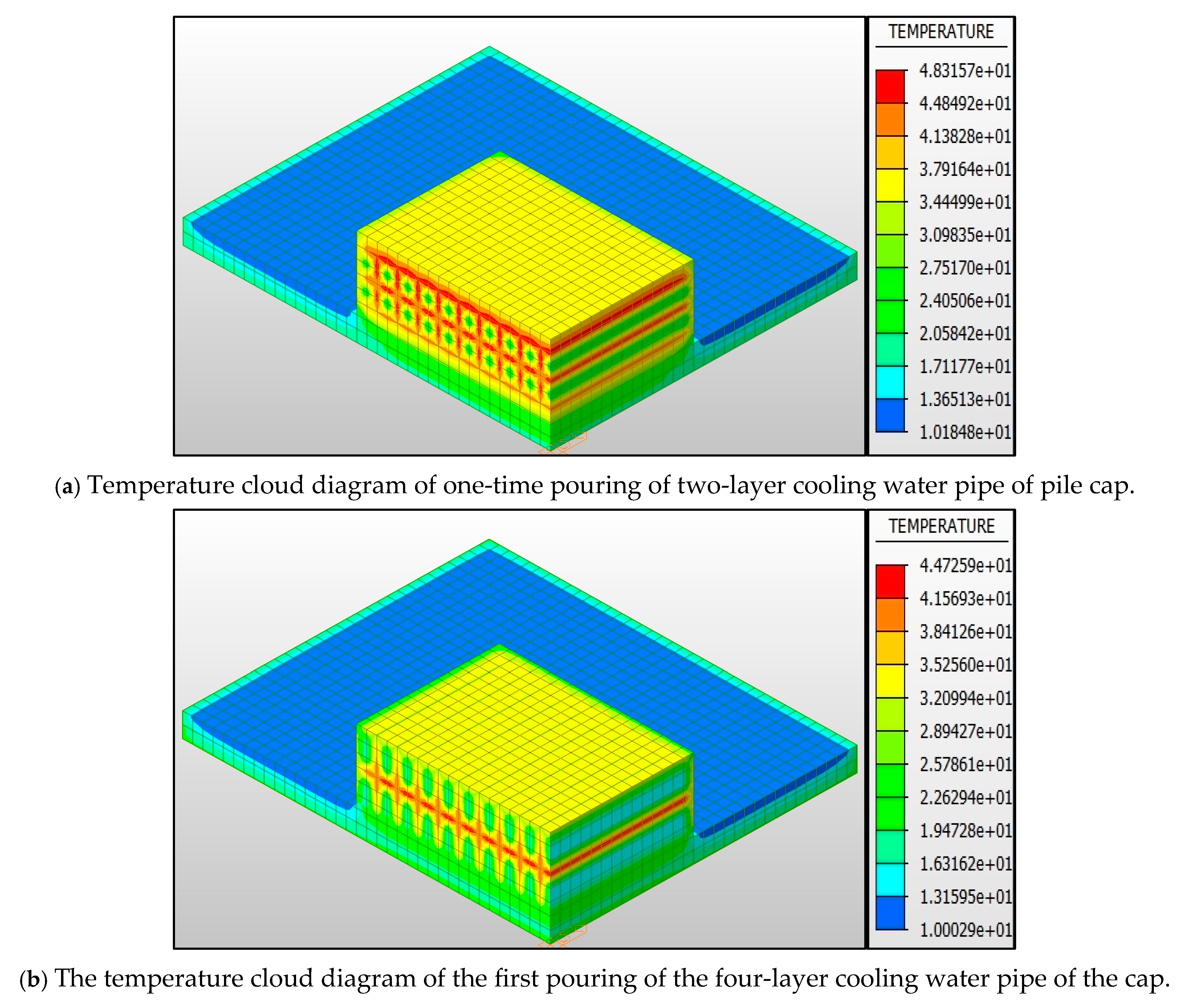
Figure 20 shows the temperature contours of these four schemes after pouring for 720 h. It can be seen from
Figure 20a that the maximum temperature of the scheme with one-time pouring and two-layer cooling water pipes is 48.32 °C, which is 15.23 °C lower than that of the scheme without cooling water pipes.
Figure 20b shows that the maximum temperature of scheme 2 (one-time pouring + four layers of cooling water pipe) is 44.73 °C, which is 4.02 °C lower than that of two layers under the same conditions, which proves that the setting of cooling water pipe inside the concrete pile cap can effectively reduce the peak value of hydration heat.
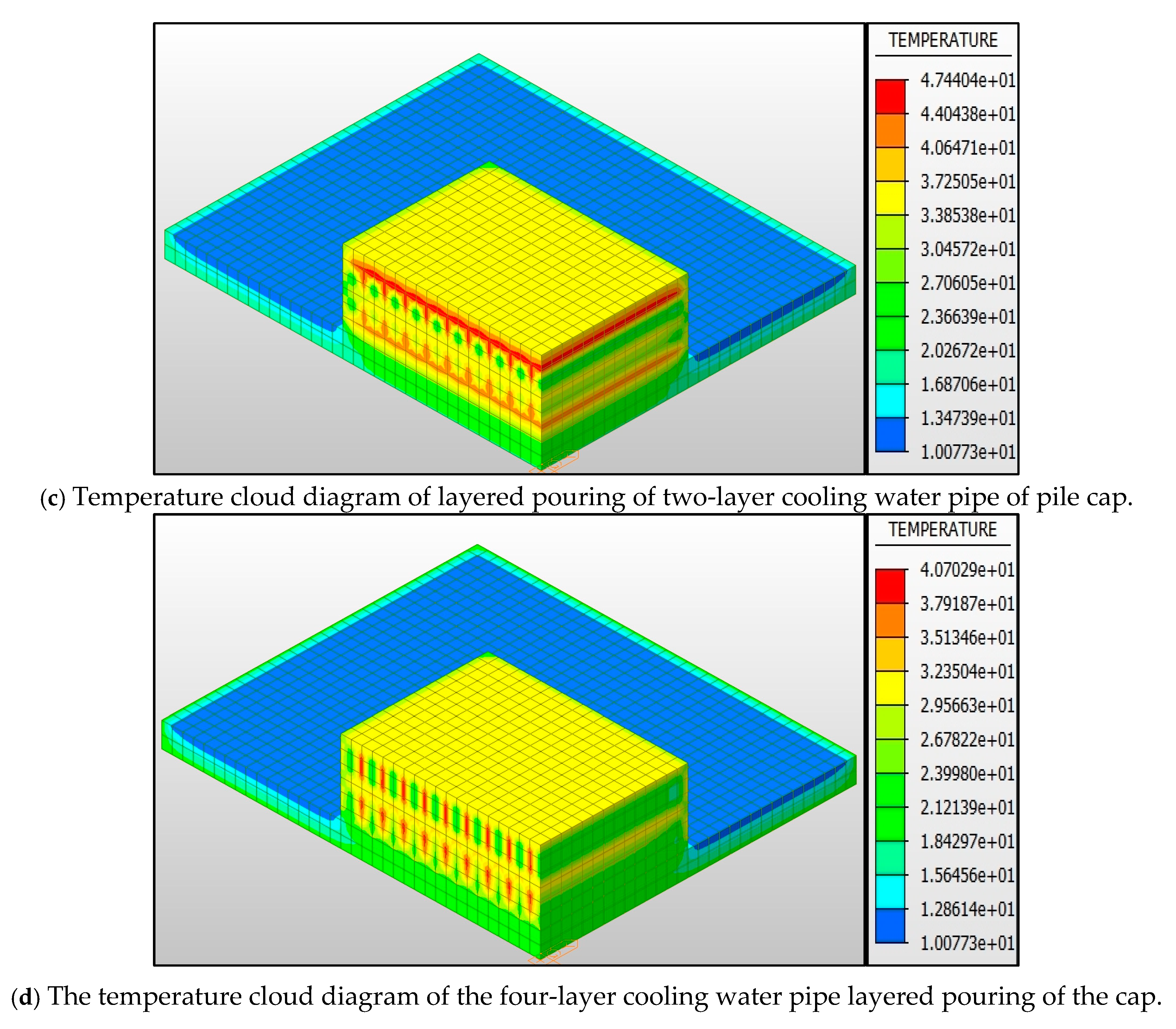
Figure 20c and
Figure 20d correspond to the scheme of layered pouring with two and four layers of cooling water pipes, respectively. The maximum temperatures are 47.44 °C and 40.70 °C, respectively, which are 0.88 °C and 4.03 °C lower than those of the scheme with the same number of layers during one-time pouring. The four schemes all meet the requirements of temperature control of mass concrete construction in ‘national high-quality project’. During the construction of mass concrete pile caps, the key is to ensure that the temperature rise of the concrete body does not exceed 40 °C, and the internal and surface temperature difference is controlled within 15 °C. The measures of layered pouring and internal installation of cooling water pipes can significantly reduce the heat generated by hydration reaction and achieve the goal of temperature control.
In order to visually display the variation law of the internal and surface temperature of the cap, this paper draws the temperature changes of the observation points A1 to A6 under different schemes and time into a line chart [
36].
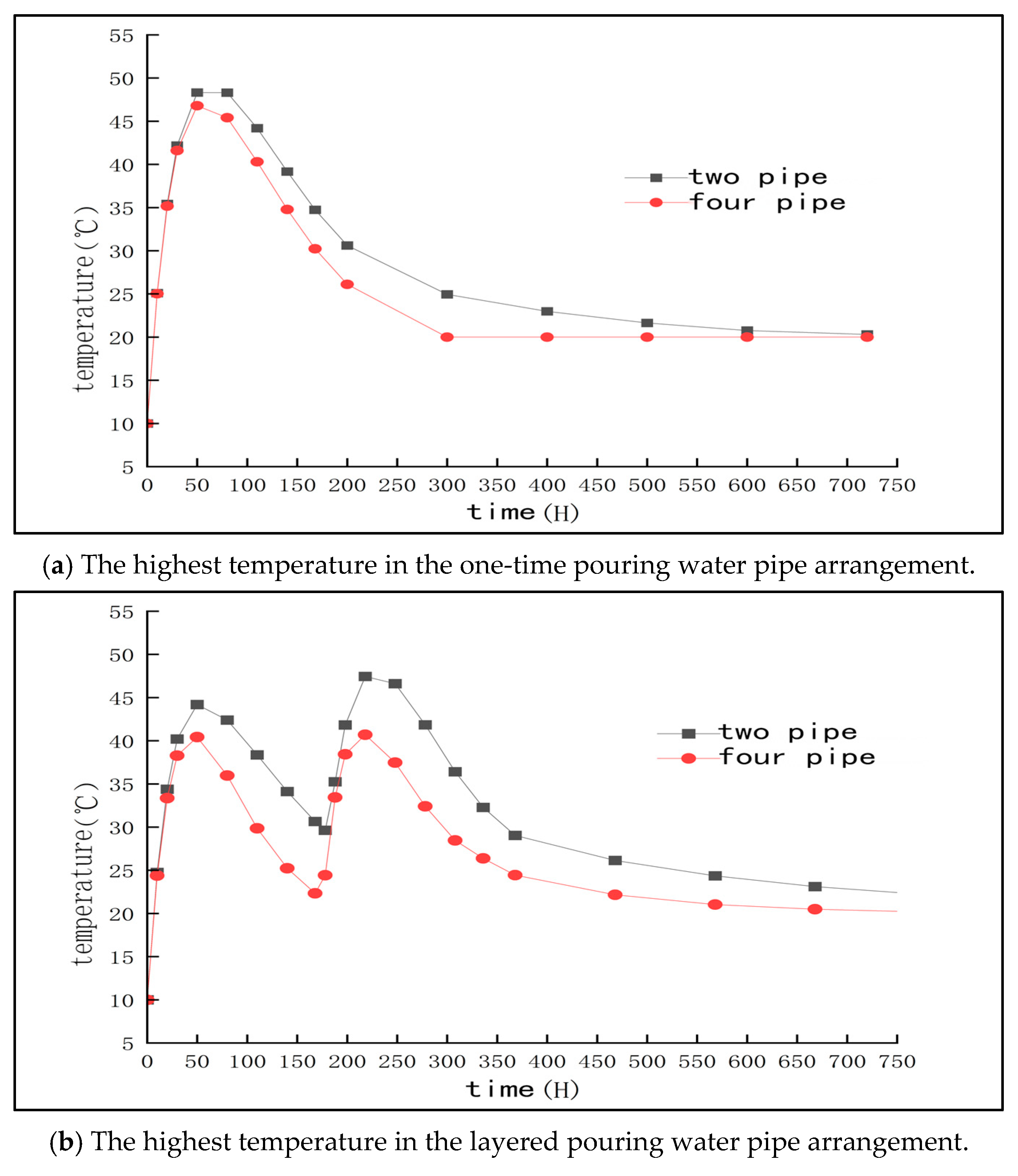
Figure 21 shows the temperature change curves of each measuring point inside the concrete under four temperature control schemes. It can be seen that the temperature evolution process of mass concrete pile caps generally shows the trend of ‘rapid heating first and then slow cooling’, and the heating rate is significantly higher than the cooling rate. In Scheme 1, the temperature of the core measuring point A5 rises rapidly and reaches a peak of 63.55 °C at about 50 h, which is the highest among all schemes, with the largest temperature gradient and the highest risk. In scheme 2, the peak temperature of the A5 point is reduced to 47.27 °C, and the temperature curve becomes relatively flat. Scheme 3 further reduces the temperature of point A5 to 36.62 ° C, and the cooling effect is significantly improved. The temperature control effect of scheme 4 is the best, and the temperature of point A5 is only 32.77 °C. The change trend of temperature curve is basically the same as that of other measuring points, indicating that the temperature rise process in the core area has been effectively suppressed. In addition, in scheme 4, the temperature distribution is more uniform and the temperature difference control is more reasonable, which is beneficial for reducing the temperature stress concentration. On the whole, the maximum temperature change curve and the highest temperature point of the central core point A5 of the pile caps with one-time pouring and two- and four-layer cooling water pipes are significantly higher than those of the other observation points, while the pile caps with layered pouring and two- and four-layer cooling water pipes are adopted. The highest temperature change curve and the highest temperature point of the A5 core point are similar to the other observation points.
Figure 22 is a comparative line chart of the maximum temperature per hour of the four schemes. It can be further observed that, with the increase in the number of layers of cooling water pipes, the peak temperature appears earlier, but the temperature control effect is more significant: the multi-layer cooling system can quickly establish a heat exchange channel, so that the core heat can be released in time to avoid long-term temperature retention in the high temperature area, showing good overall thermal control performance.
4.3. Stress Field Analysis
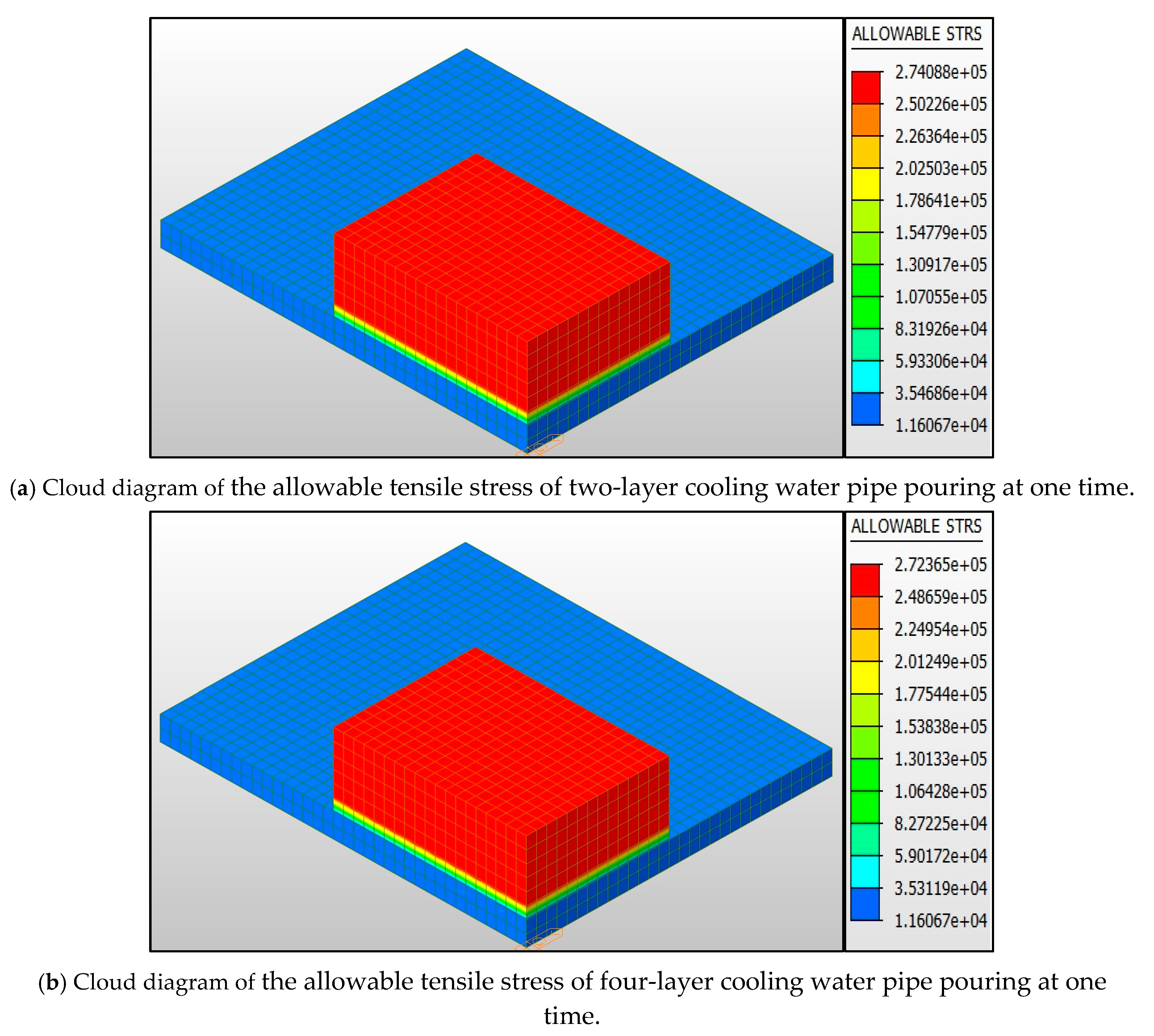
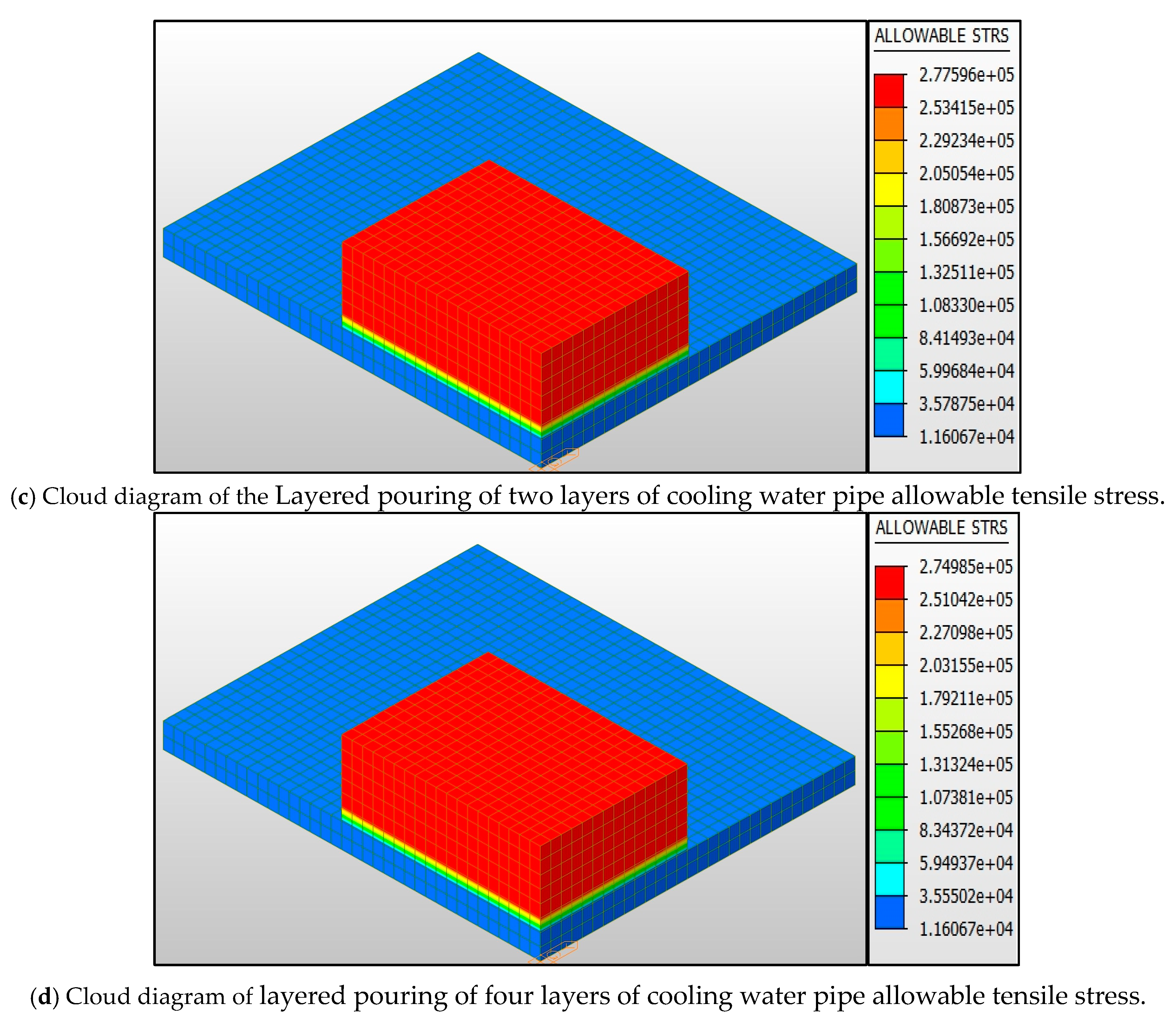
Through the analysis of finite element software (
Figure 23), the allowable tensile stress of scheme 1 to scheme 4 was found to be 2.74 MPa, 2.72 MPa, 2.76 MPa, and 2.75 MPa, respectively. It is worth noting that scheme 3 allows the highest stress value but the phenomenon of over-limit occurs, which is closely related to the spatial distribution characteristics of the maximum tensile stress. Through the analysis of the stress cloud diagram in
Figure 24,
Figure 25,
Figure 26 and
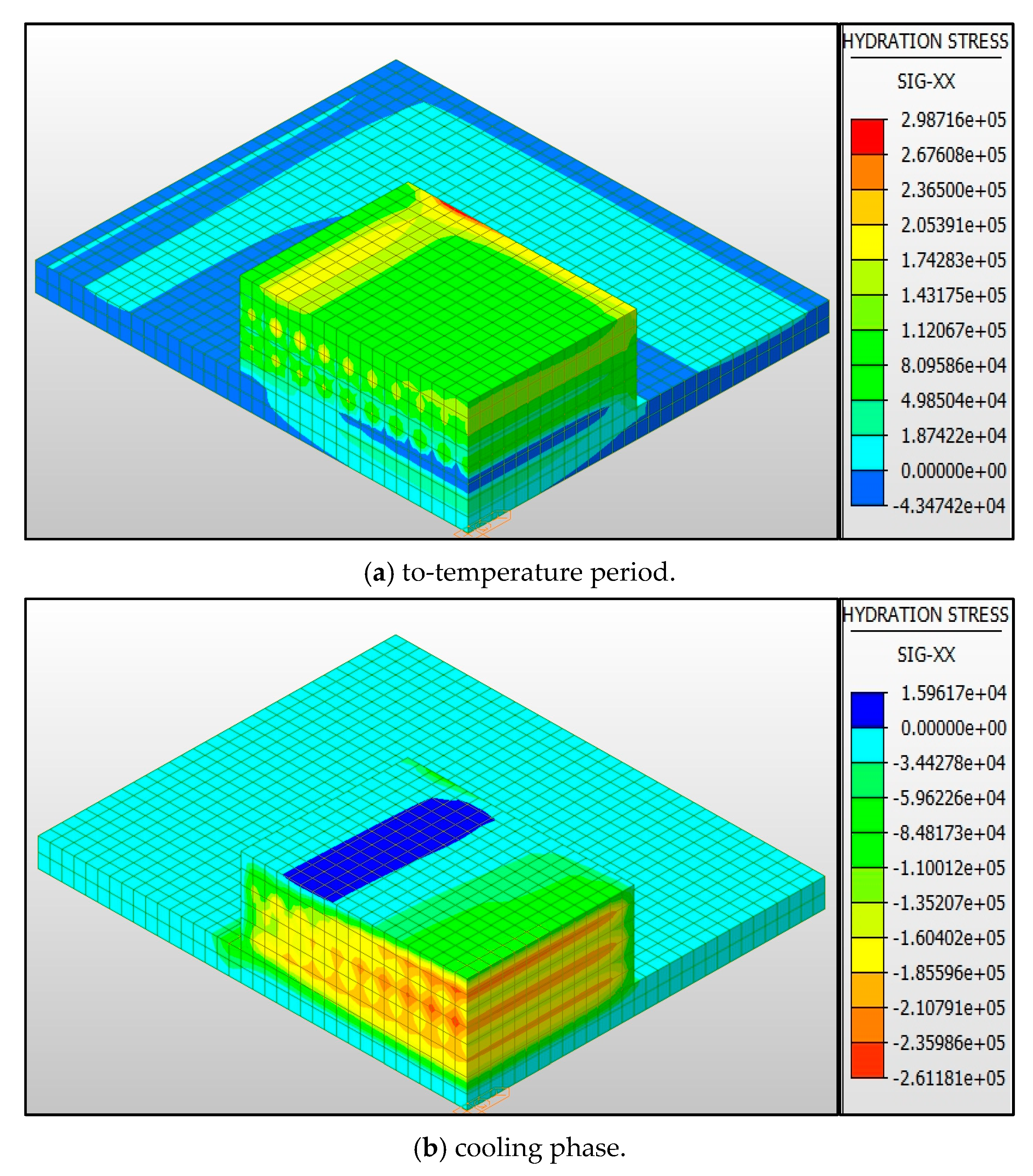
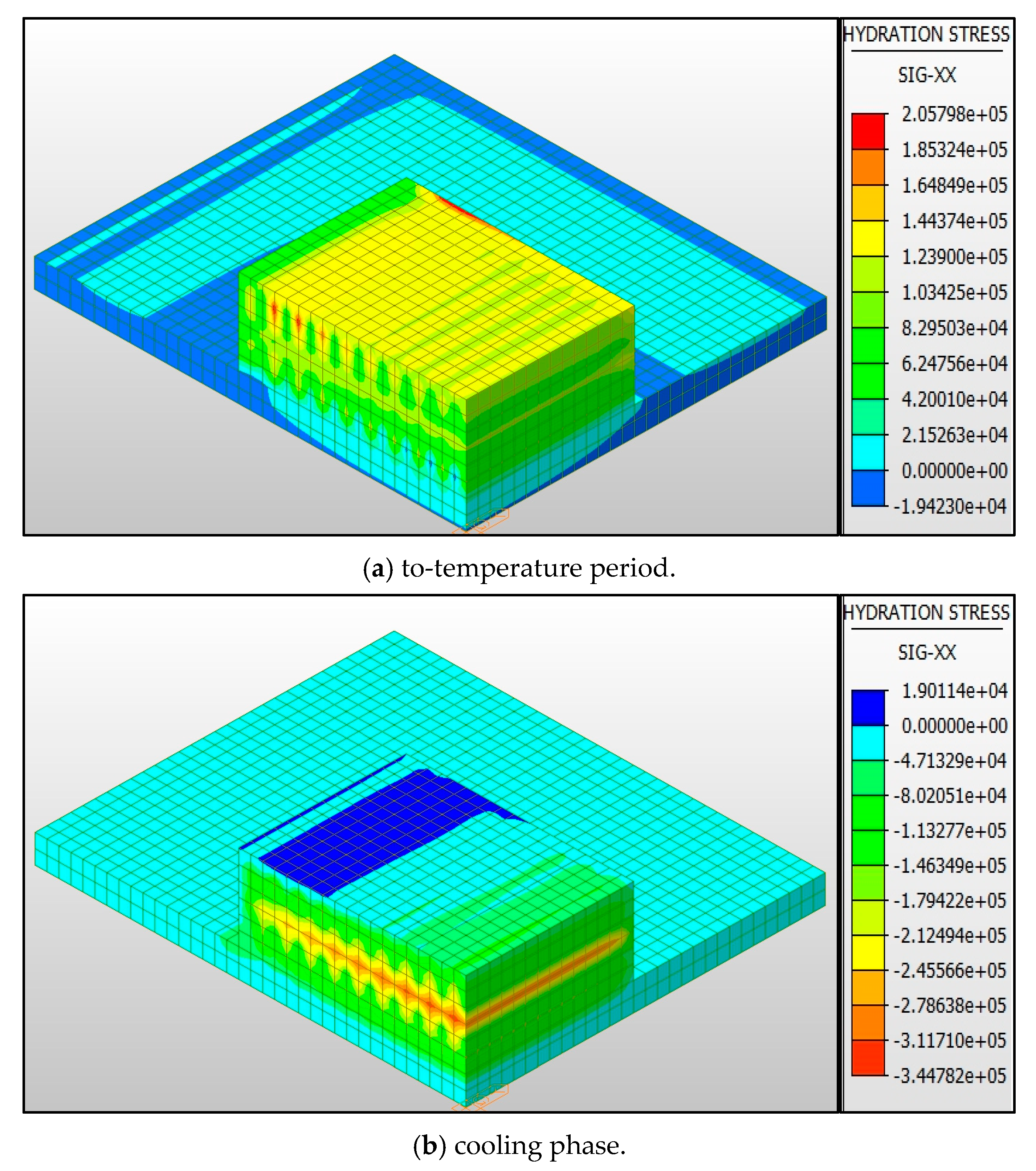
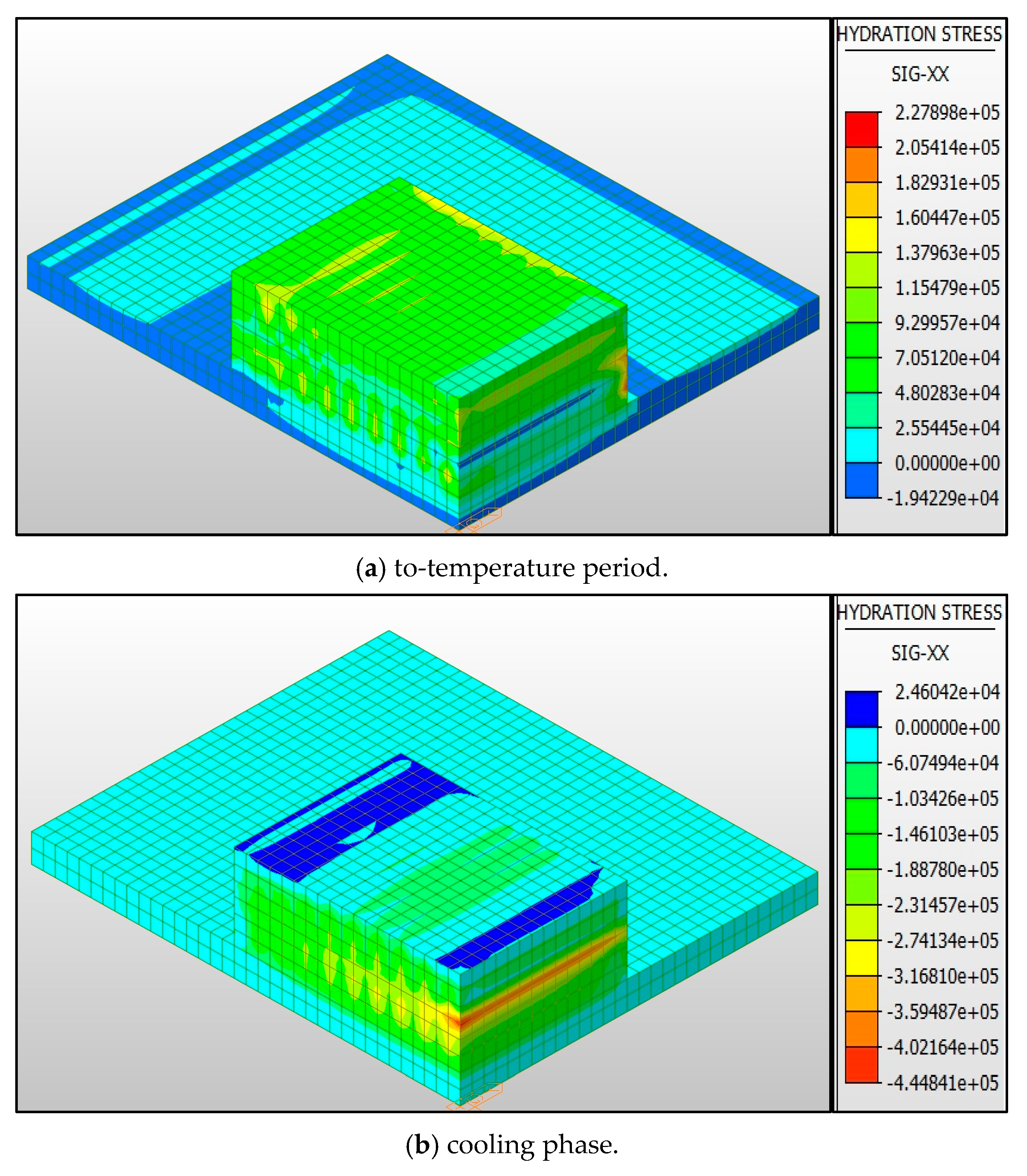
Figure 27, it is found that the maximum tensile stress (2.99 MPa) of scheme 1 in the heating stage of concrete is concentrated in the central area of the top surface, and the temperature gradient at this position reaches 12.5 °C/m, forming an obvious three-dimensional constraint effect. The maximum stress (2.06 MPa) of scheme 2 is transferred to the edge of the bottom plate, which is significantly constrained by the foundation, but the stress value is reduced by 24.4% through the arrangement of double-layer cooling pipes. Although the allowable stress of scheme 3 is higher, the butterfly-shaped stress concentration zone (maximum 2.85 MPa) is formed in the core area due to the single-layer cooling pipe, and the stress development shows obvious time-varying characteristics, reaching the peak value at 72 h after pouring. In scheme 4, the maximum stress (2.28 MPa) is distributed in the middle construction joint area through the synergistic effect of four-layer cooling pipe and three-layer pouring, and the stress non-uniformity coefficient along the thickness direction is reduced from 0.67 to 0.38 in scheme 1.
From the stress development curve, it can be seen that each scheme presents different evolution laws: the stress growth rate of scheme 1 reaches 0.12 MPa/h within 48 h after initial setting, which is significantly higher than that of other schemes; scheme 2 postpones the occurrence time of maximum stress to 96 h through early cooling control. In Scheme 3, the stress superposition phenomenon occurs after the second layer is poured, resulting in a local stress increase of 18%. Scheme 4 shows the best stress coordination ability, and the stress increase in each construction stage is controlled within 5%. This difference is due to the regulation of the cooling pipe arrangement on the hydration heat dissipation path of concrete. The multi-layer pipe group can establish a multi-dimensional heat dissipation channel, which reduces the coupling effect of temperature field and stress field by more than 37%.
It is worth noting that at the structural turning points (such as the junction of pile cap and pile cap), scheme 1 has obvious stress concentration (local stress amplification factor 2.1), while scheme 4 reduces this factor to 1.3 by layered pouring process. At the same time, the stress attenuation law of each scheme in the depth direction shows that the stress attenuation gradient of the single-layer cooling scheme (schemes 1 and 3) is 0.45 MPa/m, while the attenuation gradient of the multi-layer cooling scheme (schemes 2 and 4) is reduced to 0.28 MPa/m, which proves that the stratified cooling can effectively improve the uniformity of the cross-section stress distribution.
The above analysis shows that the synergistic effect of layered pouring and multi-layer cooling pipe controls cracks through the following mechanisms: (1) Establish a multi-stage heat dissipation system to reduce the temperature gradient in the core area (ΔTmax is reduced from 42 °C to 28 °C); (2) Optimize the construction stress path to avoid the superposition of constraint stress between different pouring layers; (3) Reconstruct the stiffness distribution of the structure to improve the stress concentration at the turning point. This composite control strategy improves the structural crack safety factor from 0.92 in scheme 1 to 1.21 in scheme 4, which provides an important reference for similar projects.
In order to discuss the variation of the stress of the center and surface joints of the pile cap with time, pouring method, and the number of layers of different cooling water pipes in more detail, the stress curves of A1, A2, A4, and A5 joints are drawn from
Figure 28,
Figure 29,
Figure 30 and
Figure 31. It can be observed from the figure that the surface stress of the cap is generally higher than the internal center area. At the same time, when layered pouring is adopted and four layers of cooling water pipes are set, the stress fluctuation of each observation point is more stable. Compared with other schemes, the fluctuation of tensile stress is smaller, and it is more difficult for cracks to form.
The analysis results reveal that the maximum tensile stress appears on the outer surface of the mass concrete of the pile cap, while the compressive stress is mainly concentrated in the middle and lower parts of the pile cap. This stress distribution phenomenon is mainly due to the heat generated during the hydration process inside the concrete, which causes the temperature to rise, resulting in internal volume expansion. When the inner concrete is trying to expand due to thermal expansion, the outer surface concrete is subjected to tensile stress due to the restriction of the internal expansion force.
Specifically, under this scheme, the stress of the cap tends to be stable after 350 h of pouring, and the fluctuation range is also small. In general, the arrangement of four layers of cooling water pipes can ensure that the stress caused by temperature change inside the pile cap is always within the specified safe range, and the surface temperature stress is effectively controlled within 350 h. The change trend is consistent with the temperature change, which is in line with the conventional engineering law. This also suggests that, after the completion of concrete pouring, appropriate thermal insulation measures still need to be taken to maintain the quality of concrete and reduce the possibility of crack formation.
4.4. Analysis of Measured Data
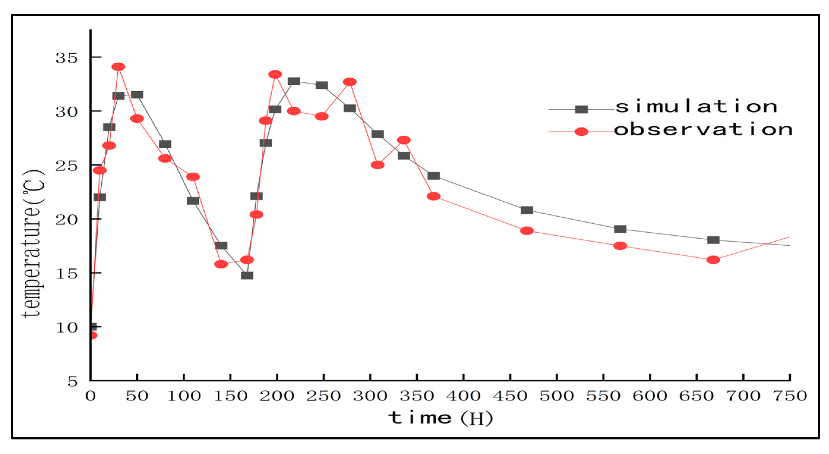
In order to verify the reliability of the numerical simulation, this study carried out on-site monitoring of the core temperature during the construction of the pile cap of the No. 13 pier of the swivel bridge in Dehui City, and compared the simulation results of the layered pouring combined with the four-layer cooling water pipe scheme, as shown in
Figure 32. The measured data acquisition frequency was once per hour, and the embedded temperature sensor (accuracy ±0.5 °C) was used to record the temperature changes of the core area (measuring point A5) and other measuring points.
It can be seen from
Figure 32 that the overall trend of the measured temperature curve is consistent with the simulation results. The measured value in the temperature rise stage (0–50 h) is 1.2–2.8 °C higher, mainly because the initial temperature of the cooling water during construction is higher than the design value (15 °C). The temperature rose to 18.2 °C, resulting in a decrease in heat exchange efficiency. In addition, the fluctuation of cement batch activity (the measured heat release rate of cementitious materials is 6.7% higher than the preset value) further aggravates the early temperature rise. In the peak stage (50–200 h), the measured maximum temperature of 42.15 °C (232 h) lags behind the simulated value by 14 h. In-depth analysis shows the following. On the one hand, the cooling water pipe is fouling. The field test shows that there is about 3% fouling on the surface of the cooling water pipe, which reduces the heat exchange efficiency between the cooling pipe and the concrete, resulting in a slower temperature release rate and a certain time delay. On the other hand, the environmental humidity fluctuates, and there is a large fluctuation in the actual environmental humidity on site. When the humidity is high, the air heat transfer efficiency decreases, which will also adversely affect the overall heat dissipation performance of the temperature control system and aggravate the delay effect of the temperature response.
However, these results all occur within the allowable range of design specifications. The measured temperature peak is reduced by 33.8% compared with the uncontrolled condition, and the maximum stress is 2.19 MPa, which is lower than the allowable value, and no structural cracks appear. The results show that the synergistic effect of layered pouring and four-layer cooling water pipe is effective, and the prediction accuracy of the model meets the engineering requirements in severe cold areas.
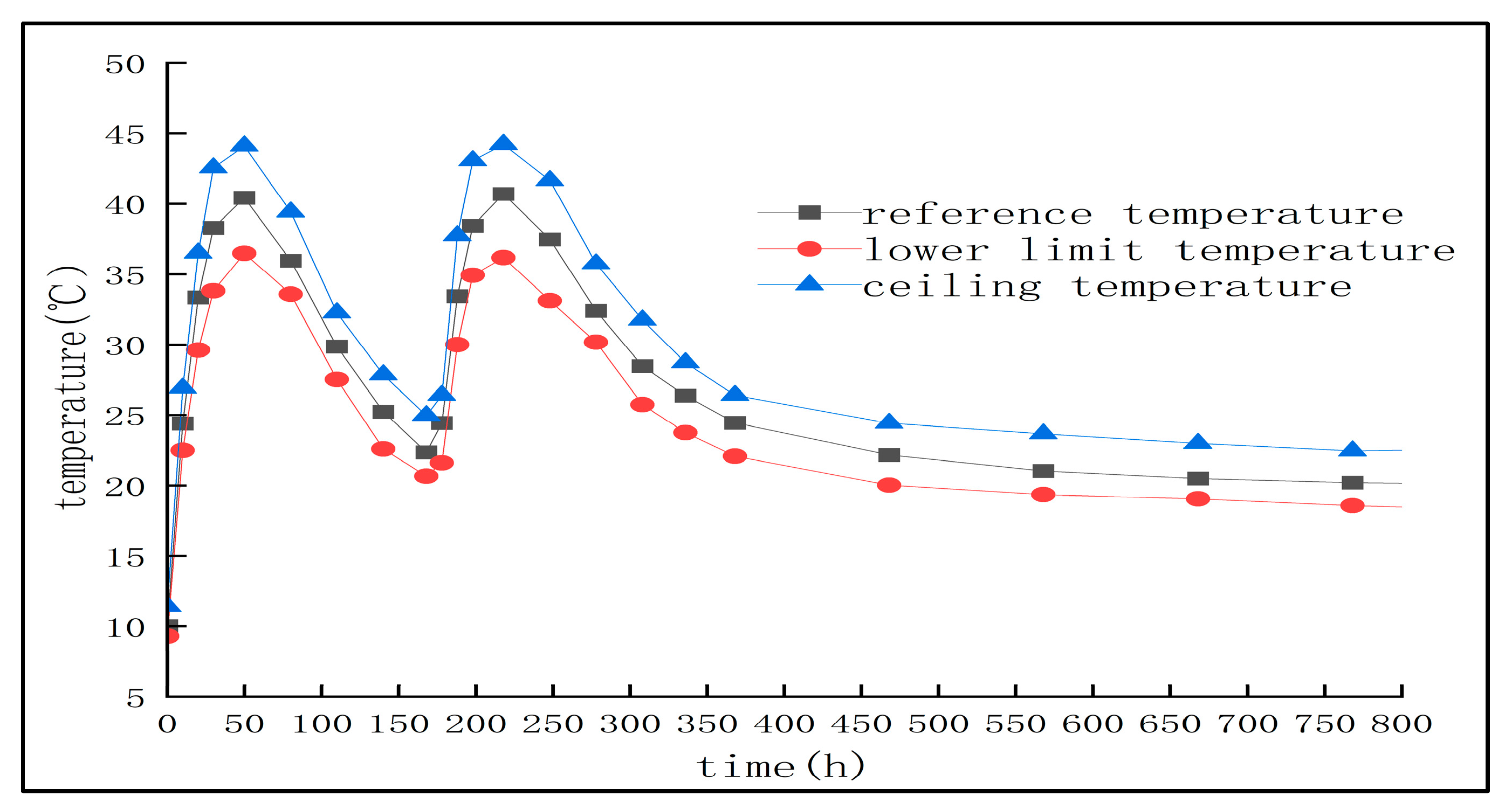
4.5. Uncertainty Discussion and Error Analysis
In order to verify the stability of the temperature control strategy proposed in this study under the fluctuation of actual construction conditions, we performed a ±10% perturbation analysis on the key parameters (such as concrete thermal conductivity and convective heat transfer coefficient) in the numerical model. Combined with the temperature data obtained from the simulation, we use the conventional sensitivity analysis method to determine the temperature peak. The results show that the peak temperature of the concrete core is about 40.7 °C at the DN40 pipeline, the flow rate is 1.2 m/s, and the error range is ±5%. The 720 h temperature curve is shown in
Figure 33. This shows that, even if there is a certain deviation in the external environment temperature or material properties, the scheme still has good temperature control effect and robustness.
4.6. Pile Cap Construction Safety Inspection
In process of constructing large concrete caps, especially in severe cold and harsh climate conditions, temperature rise control is not only related to the quality of the project, but also directly related to structural safety and long-term durability. Therefore, in the design of a layered pouring and cooling water pipe scheme, this study strictly refers to national standards, such as the ‘Technical Code for Mass Concrete Construction’, to ensure that the internal temperature rise, temperature difference, and stress of concrete during construction are within the design requirements and regulatory standards.
In addition, in order to ensure construction safety, the concrete pile cap temperature monitoring system is introduced in the project implementation stage, and the concrete temperature field and stress field are detected and recorded, and finally compared with the finite element simulation data. At the same time, when the monitoring data deviates from or exceeds the safety range, the emergency plan should be enacted immediately. Measures such as adding an insulation layer, adjusting cooling water flow, or locally correcting the pouring process should be taken to ensure the safety of the overall structure.
It is worth noting that, although the existing scheme has met the specification requirements in numerical simulation and field monitoring, in practical engineering, due to the fluctuation of external environment and the uncertainty of material parameters, it may be necessary to adjust the control strategy according to the specific situation, and maintain close communication with the relevant regulatory authorities during the construction process to ensure that the project can meet the safety and regulatory requirements throughout the entire process.


