Performance Degradation Law and Model Construction of Hydraulic Concrete Under Freeze-Thaw Cycles: A Comprehensive Review


Abstract
1. Introduction
2. Theory and Characterization Methods of FT Damage for Concrete
2.1. Theory of FT Damage
2.2. Effect of Air Content on FT Performance
2.3. Characterization of FT Damage Based on CT Technology
3. Fracture Characteristics of Concrete Under FT Cycles
4. Tensile Characteristics of Concrete Under FT Cycles
5. Triaxial Test and Numerical Simulation of Concrete Under FT Action
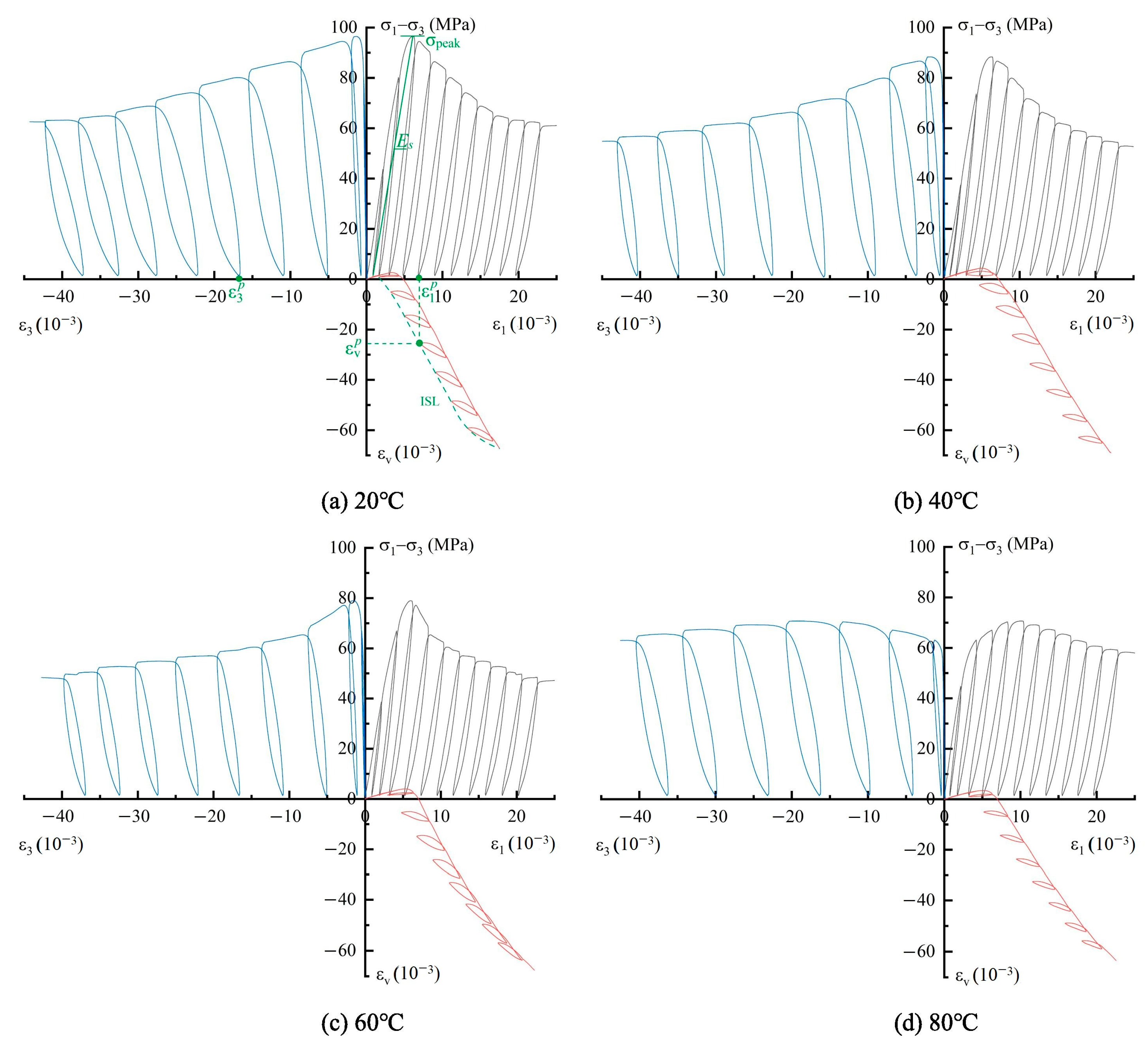
5.1. Static Triaxial Characteristics
5.2. Dynamic Triaxial Characteristics
5.3. Numerical Analysis
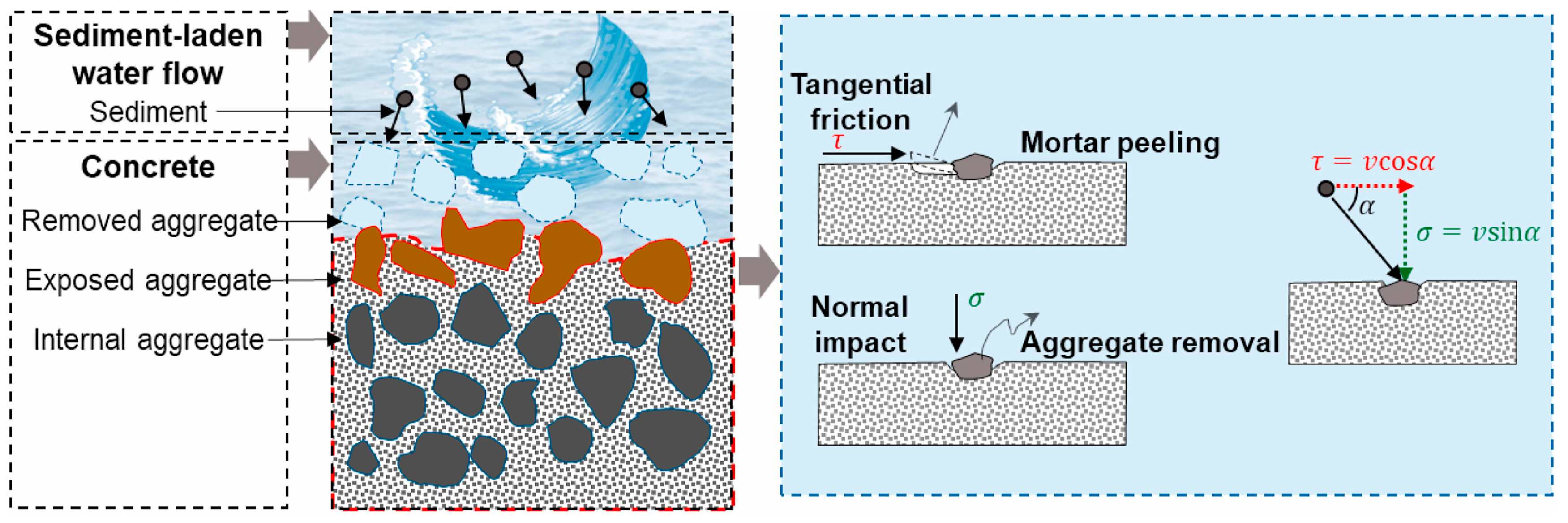
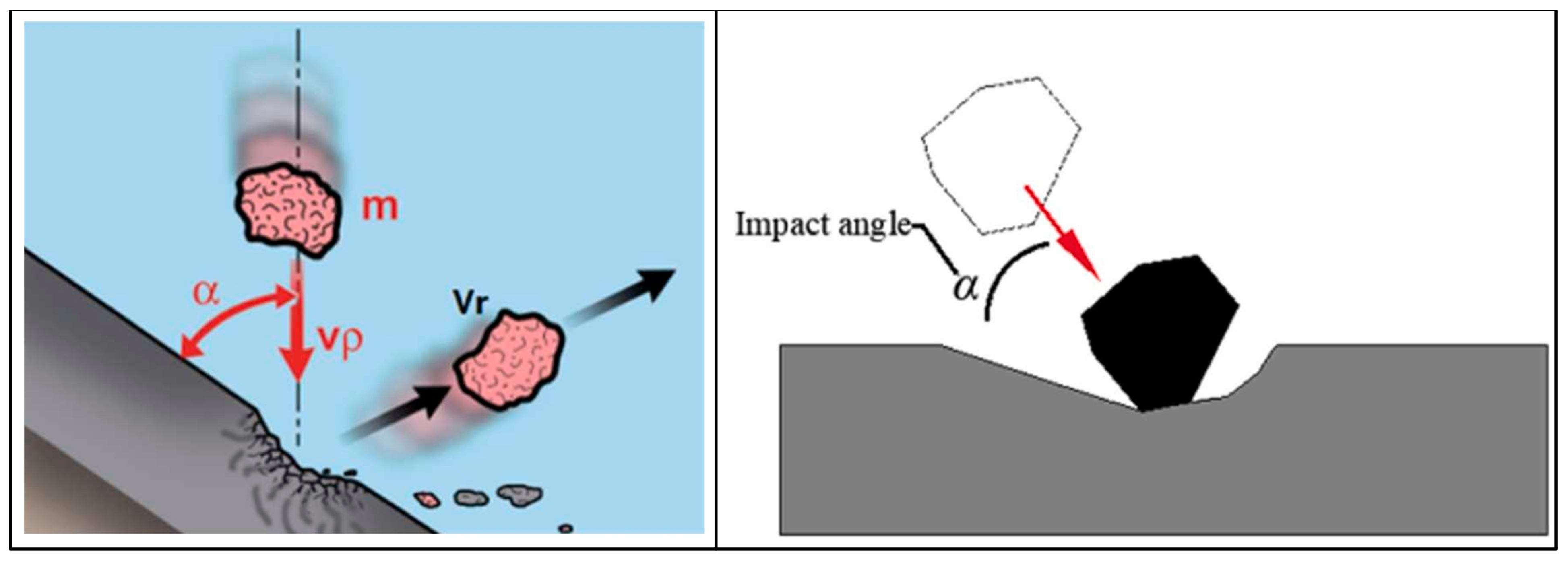
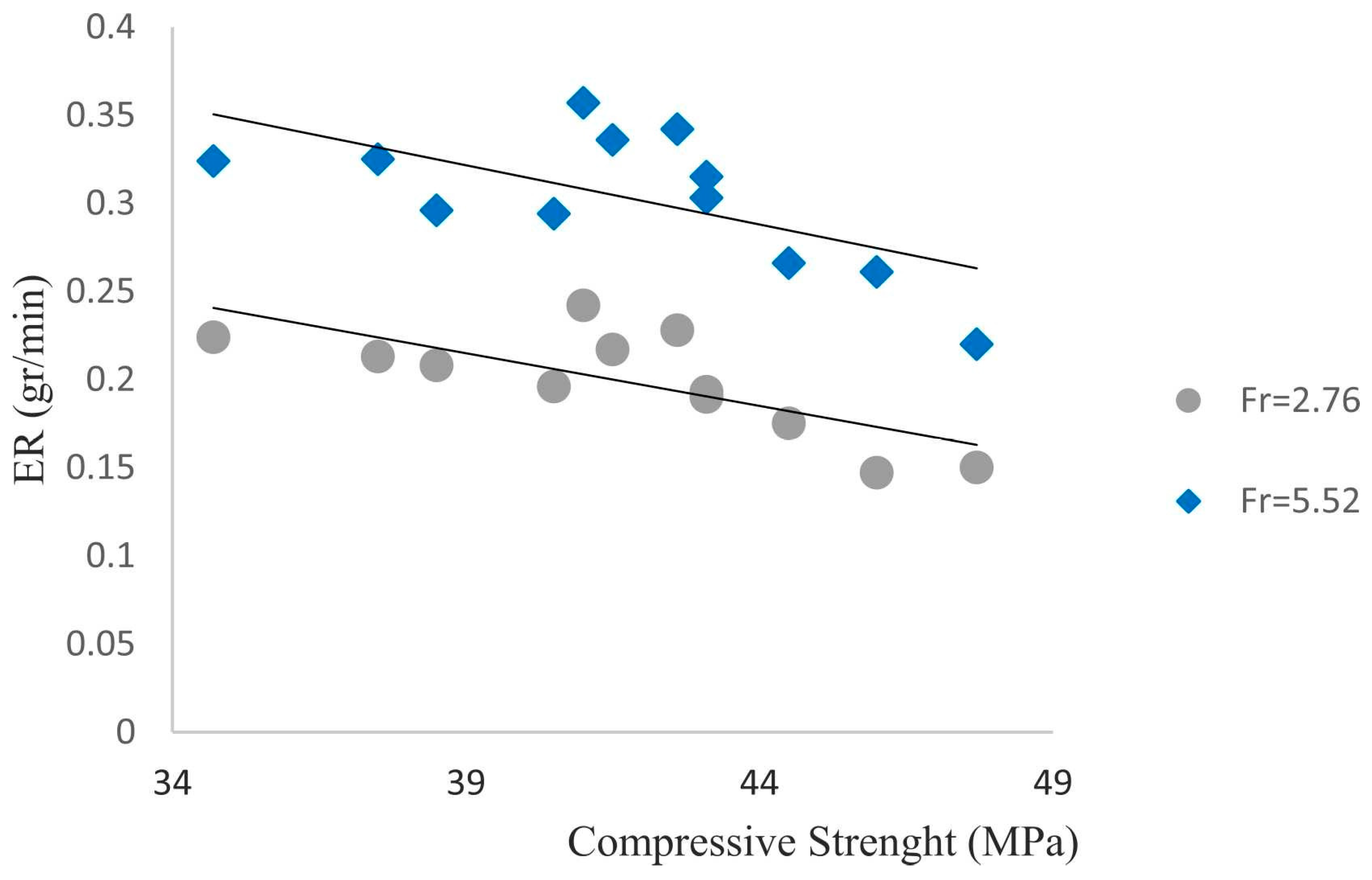
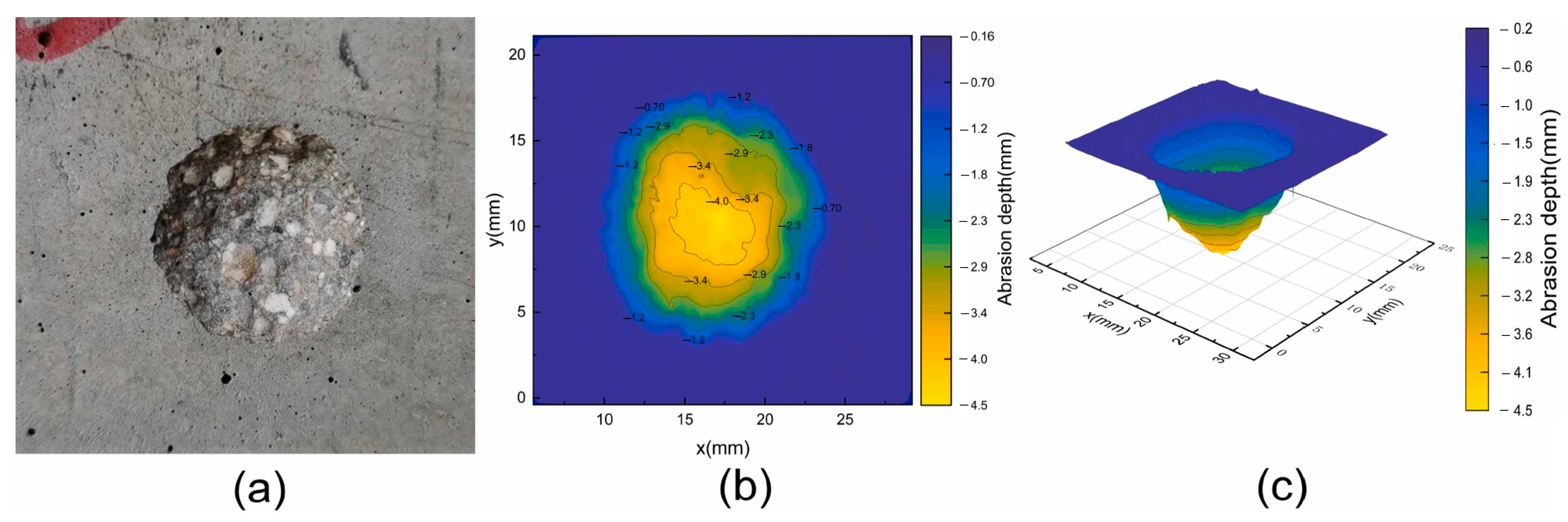
6. Wear Resistance Characteristics and Prediction Model of Concrete Under FT Cycles
7. Conclusions and Perspectives
Author Contributions
Funding
Conflicts of Interest
References
- Sicat, E.; Gong, F.; Zhang, D.; Ueda, T. Change of the coefficient of thermal expansion of mortar due to damage by freeze thaw cycles. J. Adv. Concr. Technol. 2013, 11, 333–346. [Google Scholar] [CrossRef]
- Jiang, W.Q.; Shen, X.H.; Xia, J.; Mao, L.X.; Yang, J.; Liu, Q.F. A numerical study on chloride diffusion in freeze-thaw affected concrete. Constr. Build. Mater. 2018, 179, 553–565. [Google Scholar] [CrossRef]
- Zhang, Z.; Liu, Q.; Wu, Q.; Xu, H.; Liu, P.; Oeser, M. Damage evolution of asphalt mixture under freeze-thaw cyclic loading from a mechanical perspective. Int. J. Fatigue 2021, 142, 105923. [Google Scholar] [CrossRef]
- Hasan, M.; Okuyama, H.; Sato, Y.; Ueda, T. Stress-strain model of concrete damaged by freezing and thawing cycles. J. Adv. Concr. Technol. 2004, 2, 89–99. [Google Scholar] [CrossRef]
- Li, B.; Mao, J.; Shen, W.; Liu, H.; Liu, X.; Xu, G. Mesoscopic cracking model of cement-based materials subjected to freeze-thaw cycles. Constr. Build. Mater. 2019, 211, 1050–1064. [Google Scholar] [CrossRef]
- Fan, B.; Guo, B.; Gao, Y.; Yu, J.; Hu, S. Study of fracture parameters and complete fracture process of concrete at low temperatures using an energy approach. Eng. Fract. Mech. 2022, 263, 108274. [Google Scholar] [CrossRef]
- Chen, X.; Chen, C. Experimental study on damage evolution behavior of self-compacting rubberized concrete under direct tensile fatigue loading. KSCE J. Civ. Eng. 2020, 24, 3300–3308. [Google Scholar] [CrossRef]
- Shi, L.; Wang, L.; Song, Y.; Shen, L. Dynamic multiaxial strength and failure criterion of dam concrete. Constr. Build. Mater. 2014, 66, 181–191. [Google Scholar] [CrossRef]
- Yang, S.Q.; Fan, J.C.; Liu, M.T.; Li, D.N.; Li, J.L.; Han, L.H.; Wang, J.J.; Yang, S.Y.; Dai, S.W.; Zhang, L.B. Research on the solid particle erosion wear of pipe steel for hydraulic fracturing based on experiments and numerical simulations. Pet. Sci. 2024, 21, 2779–2792. [Google Scholar] [CrossRef]
- Xu, S.; Reinhardt, H.W. A simplified method for determining double-K fracture parameters for three-point bending tests. Int. J. Fract. 2000, 104, 181–209. [Google Scholar] [CrossRef]
- Mindess, S.; Young, J.F.; Darwin, D. Concrete; Prentice Hall PTR: Upper Saddle River, NJ, USA, 2003. [Google Scholar]
- Sfer, D.; Carol, I.; Gettu, R.; Etse, G. Study of the behavior of concrete under triaxial compression. J. Eng. Mech. 2002, 128, 156–163. [Google Scholar] [CrossRef]
- Kothandaraman, S.; Kandasamy, S. The effect of controlled permeable formwork (CPF) liner on the surface quality of concretes. Cem. Concr. Compos. 2017, 76, 48–56. [Google Scholar] [CrossRef]
- Powers, T.C. A working hypothesis for further studies of frost resistance of concrete. J. Proc. 1945, 41, 245–272. [Google Scholar]
- Powers, T.C.; Willis, T.F. The air requirement of frost-resistant concrete. In Highway Research Board, Proceedings of the 29th Annual Meeting, Washington, DC, USA, 13–16 December 1949; National Academy of Sciences-National Research Council: Washington, DC, USA, 1950; Volume 29. [Google Scholar]
- Coussy, O.; Monteiro, P.J. Poroelastic model for concrete exposed to freezing temperatures. Cem. Concr. Res. 2008, 38, 40–48. [Google Scholar] [CrossRef]
- Powers, T.C.; Helmuth, R.A. Theory of volume changes in hardened portland-cement paste during freezing. In Highway Research Board, Proceedings of the Thirty-Second Annual Meeting, Washington, DC, USA, 13–16 January 1953; Highway Research Board: Washington, DC, USA, 1953; Volume 32. [Google Scholar]
- Valenza, J.J., II; Scherer, G.W. A review of salt scaling: II. Mechanisms. Cem. Concr. Res. 2007, 37, 1022–1034. [Google Scholar]
- Fagerlund, G. The Critical Spacing Factor; Report TVBM-7058; Lund Institute of Technology, Division of Building Materials: Lund, Sweden, 1993. [Google Scholar]
- Fagerlund, G. The international cooperative test of the critical degree of saturation method of assessing the freeze/thaw resistance of concrete. Matér. Constr. 1977, 10, 231–253. [Google Scholar] [CrossRef]
- Fagerlund, G. A Service Life Model for Internal Frost Damage in Concrete; Report TVBM-3119; Lund University: Lund, Sweden, 2004. [Google Scholar]
- Snyder, K.A. A numerical test of air void spacing equations. Adv. Cem. Based Mater. 1998, 8, 28–44. [Google Scholar] [CrossRef]
- Hasholt, M.T. Air void structure and frost resistance: A challenge to Powers’ spacing factor. Mater. Struct. 2014, 47, 911–923. [Google Scholar] [CrossRef]
- Zeng, Q.; Fen-Chong, T.; Dangla, P.; Li, K. A study of freezing behavior of cementitious materials by poromechanical approach. Int. J. Solids Struct. 2011, 48, 3267–3273. [Google Scholar] [CrossRef]
- Mayercsik, N.P.; Vandamme, M.; Kurtis, K.E. Assessing the efficiency of entrained air voids for freeze-thaw durability through modeling. Cem. Concr. Res. 2016, 88, 43–59. [Google Scholar] [CrossRef]
- Wei, Y.; Chen, X.; Chai, J.; Qin, Y. Correlation between mechanical properties and pore structure deterioration of recycled concrete under sulfate freeze-thaw cycles: An experimental study. Constr. Build. Mater. 2024, 412, 134794. [Google Scholar] [CrossRef]
- Powers, T.C. The Mechanism of Frost Action in Concrete; Road Research Laboratory Publication: London, UK, 1965. [Google Scholar]
- Liu, Z.; Hansen, W. A geometrical model for void saturation in air-entrained concrete under continuous water exposure. Constr. Build. Mater. 2016, 124, 475–484. [Google Scholar] [CrossRef]
- Moradllo, M.K.; Qiao, C.; Hall, H.; Ley, M.T.; Reese, S.R.; Weiss, W.J. Quantifying fluid filling of the air voids in air entrained concrete using neutron radiography. Cem. Concr. Compos. 2019, 104, 103407. [Google Scholar] [CrossRef]
- Yang, C.; Zhang, J.; Wang, J.; Guo, M. Post-evaluation of frost resistance of cement concrete entities based on pore spacing factors of hardened concrete. Constr. Build. Mater. 2024, 411, 134342. [Google Scholar] [CrossRef]
- Peng, G.F.; Ma, Q.; Hu, H.M.; Gao, R.; Yao, Q.F.; Liu, Y.F. The effects of air entrainment and pozzolans on frost resistance of 50–60 MPa grade concrete. Constr. Build. Mater. 2007, 21, 1034–1039. [Google Scholar] [CrossRef]
- Xu, L.; Zhang, C.; Wang, J.; Du, Z.; Hu, X.; Yang, Q.; Li, F.; Li, Z.; He, P. Service life prediction of concrete with combined air-entraining admixture and fibers under freeze-thaw cycles based on critical water saturation theory. J. Mater. Civ. Eng. 2024, 36, 04024274. [Google Scholar] [CrossRef]
- Du, P.; Yao, Y.; Wang, L.; Xu, D.; Zhou, Z.; Sun, J.; Cheng, X. Using strain to evaluate influence of air content on frost resistance of concrete. Cold Reg. Sci. Technol. 2019, 157, 21–29. [Google Scholar] [CrossRef]
- Farooq, M.A.; Sato, Y.; Niitani, K. Experimental investigation of monotonic behavior and stress-strain models of AE and non-AE high strength concrete with BFS fine aggregates under freezing and thawing. Constr. Build. Mater. 2020, 249, 118679. [Google Scholar] [CrossRef]
- Wu, Z.; Libre, N.A.; Khayat, K.H. Factors affecting air-entrainment and performance of roller compacted concrete. Constr. Build. Mater. 2020, 259, 120413. [Google Scholar] [CrossRef]
- Shang, H.S.; Yi, T.H. Freeze-thaw durability of air-entrained concrete. Sci. World J. 2013, 2013, 650791. [Google Scholar] [CrossRef]
- Hang, M.; Cui, L.; Wu, J.; Sun, Z. Freezing-thawing damage characteristics and calculation models of aerated concrete. J. Build. Eng. 2020, 28, 101072. [Google Scholar] [CrossRef]
- Shang, H.; Song, Y.; Ou, J. Behavior of air-entrained concrete after freeze-thaw cycles. Acta Mech. Solida Sin. 2009, 22, 261–266. [Google Scholar] [CrossRef]
- Shang, H. Triaxial T-C-C behavior of air-entrained concrete after freeze-thaw cycles. Cold Reg. Sci. Technol. 2013, 89, 1–6. [Google Scholar] [CrossRef]
- Liu, K.; Yan, J.; Hu, Q.; Sun, Y.; Zou, C. Effects of parent concrete and mixing method on the resistance to freezing and thawing of air-entrained recycled aggregate concrete. Constr. Build. Mater. 2016, 106, 264–273. [Google Scholar] [CrossRef]
- Wang, R.; Hu, Z.; Li, Y.; Wang, K.; Zhang, H. Review on the deterioration and approaches to enhance the durability of concrete in the freeze-thaw environment. Constr. Build. Mater. 2022, 321, 126371. [Google Scholar] [CrossRef]
- He, R.; Nantung, T.; Lu, N.L. Unraveling microstructural evolution in air-entrained mortar and paste: Insights from MIP and micro-CT tomography amid cyclic freezing-thawing damage. J. Build. Eng. 2024, 94, 109922. [Google Scholar] [CrossRef]
- Li, X.; Sun, G. Optimal freeze-thaw resistance air-entrained concrete with designed nanoparticle stabilised bubble system. Constr. Build. Mater. 2024, 435, 136769. [Google Scholar] [CrossRef]
- Wang, Y.; Hu, Z.; Liu, J. Freeze-thaw resistance of concrete containing azodicarbonamide expansive agent. Constr. Build. Mater. 2023, 367, 130335. [Google Scholar] [CrossRef]
- Mac, M.J.; Yio, M.H.; Desbois, G.; Casanova, I.; Wong, H.S.; Buenfeld, N.R. 3D imaging techniques for characterising microcracks in cement-based materials. Cem. Concr. Res. 2021, 140, 106309. [Google Scholar] [CrossRef]
- Dong, X.; Yu, T.; Zhang, Q.; Natarajan, S. A framework to model freeze/thaw-induced crack propagation in concrete based on a fatigue phase-field method. Eng. Fract. Mech. 2024, 306, 110260. [Google Scholar] [CrossRef]
- Khan, R.M.A.; Shafighfard, T.; Ali, H.Q.; Mieloszyk, M.; Yildiz, M. Strength prediction and experimental damage investigations of plain woven CFRPs with interacting holes using multi-instrument measurements. Polym. Compos. 2023, 44, 3594–3609. [Google Scholar] [CrossRef]
- Fan, S.; Ren, H.; Hong, S.; Xing, F.; Hou, D.; Dong, B. Interfacial mechanical bond characterization between cement pastes and porous aggregates through a coupled XCT and DVC technique. Cem. Concr. Compos. 2023, 142, 105158. [Google Scholar] [CrossRef]
- Miarka; Kytýř, D.; Koudelka, P.; Bílek, V. Damage localisation in fresh cement mortar observed via in situ (timelapse) X-ray μCT imaging. Cem. Concr. Compos. 2024, 154, 105736. [Google Scholar] [CrossRef]
- Feng, L.; Chen, X.; Feng, Z.; Ning, Y. Mesoscale damage detection and surface deterioration of Freeze-Thawed concrete cores using 3D CT scanning and roughness quantification. J. Mater. Civ. Eng. 2024, 36, 04023592. [Google Scholar] [CrossRef]
- Shields, Y.; Garboczi, E.; Weiss, J.; Farnam, Y. Freeze-thaw crack determination in cementitious materials using 3D X-ray computed tomography and acoustic emission. Cem. Concr. Compos. 2018, 89, 120–129. [Google Scholar] [CrossRef]
- Sokhansefat, G.; Moradian, M.; Finnell, M.; Behravan, A.; Ley, M.T.; Lucero, C.; Weiss, J. Using X-ray computed tomography to investigate mortar subjected to freeze-thaw cycles. Cem. Concr. Compos. 2020, 108, 103520. [Google Scholar] [CrossRef]
- Chen, J.; Deng, X.; Luo, Y.; He, L.; Liu, Q.; Qiao, X. Investigation of microstructural damage in shotcrete under a freeze-thaw environment. Constr. Build. Mater. 2015, 83, 275–282. [Google Scholar] [CrossRef]
- Luo, Q.; Liu, D.X.; Qiao, P.; Feng, Q.G.; Sun, L.Z. Microstructural damage characterization of concrete under freeze-thaw action. Int. J. Damage Mech. 2018, 27, 1551–1568. [Google Scholar] [CrossRef]
- Paswan, R.; Das, S. Elucidating the evolution of pore structure. microstructural damage, and micromechanical response in cement pastes containing microencapsulated phase change materials under freeze-thaw conditions. Cem. Concr. Compos. 2024, 154, 105743. [Google Scholar] [CrossRef]
- Promentilla, M.A.B.; Sugiyama, T. X-ray microtomography of mortars exposed to freezing-thawing action. J. Adv. Concr. Technol. 2010, 8, 97–111. [Google Scholar] [CrossRef]
- Liu, M.; Qiao, P.; Sun, L. Dependence of chloride ion diffusivity on evolution of pore-structures in freeze-thawed shotcrete: Multiscale characterization and modeling. Cem. Concr. Compos. 2021, 123, 104222. [Google Scholar] [CrossRef]
- Hain, M.; Wriggers, P. Computational homogenization of micro-structural damage due to frost in hardened cement paste. Finite Elem. Anal. Des. 2008, 44, 233–244. [Google Scholar] [CrossRef]
- Atasham, M.; Xia, P.; Khan, S.; Tahir, M.; Hassam, M.; Gong, F.; Zhao, Y. Characterizations and quantification of freeze-thaw behaviors of recycled brick aggregate concrete. J. Build. Eng. 2024, 86, 108821. [Google Scholar] [CrossRef]
- Zhuang, L.D.; Wu, S.; Wang, W.; Huang, Y. Development of a novel crack-resistance technique for concrete slab in the hogging moment region of continuous composite beam. Eng. Struct. 2025, 322, 119111. [Google Scholar] [CrossRef]
- Kazemi, F.; Shafighfard, T.; Yoo, D.Y. Data-driven modeling of mechanical properties of fiber-reinforced concrete: A critical review. Arch. Comput. Methods Eng. 2024, 31, 2049–2078. [Google Scholar] [CrossRef]
- Lang, L.; Luo, Z.; Yuan, Q.; Zhu, Z.; Zhou, L.; Xu, Q.; Tang, X.; Gao, H.; Cao, J.; Gan, Z. Crack arrest characteristics and dynamic fracture parameters of moving cracks encountering double holes under impact loads. Int. J. Impact Eng. 2025, 195, 105158. [Google Scholar] [CrossRef]
- Xu, Y.; Chen, H.; Liang, Y.; Shen, J.; Yang, H. Study on fracture characteristics and fracture mechanism of fully recycled aggregate concrete using AE and DIC techniques. Constr. Build. Mater. 2024, 419, 135540. [Google Scholar] [CrossRef]
- Pigeon, M.; Marchand, J.; Pleau, R. Frost resistant concrete. Constr. Build. Mater. 1996, 10, 339–348. [Google Scholar] [CrossRef]
- Šelih, J. Performance of concrete exposed to freezing and thawing in different saline environments. J. Civ. Eng. Manag. 2010, 16, 306–311. [Google Scholar] [CrossRef]
- Liu, L.; Shen, D.; Chen, H.; Sun, W.; Qian, Z.; Zhao, H.; Jiang, J. Analysis of damage development in cement paste due to ice nucleation at different temperatures. Cem. Concr. Compos. 2014, 53, 1–9. [Google Scholar] [CrossRef]
- Liu, M.; Lu, J.; Ming, P.; Yu, J. Study on the fracture properties of concrete considering salt-freeze-thaw damage. Constr. Build. Mater. 2024, 448, 138147. [Google Scholar] [CrossRef]
- Jóźwiak-Niedźwiedzka, D. Scaling resistance of high performance concretes containing a small portion of pre-wetted lightweight fine aggregate. Cem. Concr. Compos. 2005, 27, 709–715. [Google Scholar] [CrossRef]
- Hanjari, K.Z.; Utgenannt, P.; Lundgren, K. Experimental study of the material and bond properties of frost-damaged concrete. Cem. Concr. Res. 2011, 41, 244–254. [Google Scholar] [CrossRef]
- Zhou, D.; Chen, D.; Yang, F.; Mei, J.; Yao, Y.; Deng, Y. Freeze-thaw damage analysis and life prediction of modified pervious concrete based on Weibull distribution. Case Stud. Constr. Mater. 2024, 20, e03305. [Google Scholar] [CrossRef]
- Reis, J.M.L.; Ferreira, A.J.M. Freeze-thaw and thermal degradation influence on the fracture properties of carbon and glass fiber reinforced polymer concrete. Constr. Build. Mater. 2006, 20, 888–892. [Google Scholar] [CrossRef]
- Kanellopoulos, A.; Farhat, F.A.; Nicolaides, D.; Karihaloo, B.L. Mechanical and fracture properties of cement-based bi-materials after thermal cycling. Cem. Concr. Res. 2009, 39, 1087–1094. [Google Scholar] [CrossRef]
- Xu, H.; Bu, J.; Chen, X.; Chen, Q.; Xu, B. Fracture behavior of dredged sand concrete under freeze-thaw cycles. Constr. Build. Mater. 2023, 366, 130192. [Google Scholar] [CrossRef]
- Kosior-Kazberuk, M. Variations in fracture energy of concrete subjected to cyclic freezing and thawing. Arch. Civ. Mech. Eng. 2013, 13, 254–259. [Google Scholar] [CrossRef]
- Ma, Z.; Zhao, T.; Yang, J. Fracture behavior of concrete exposed to the freeze-thaw environment. J. Mater. Civ. Eng. 2017, 29, 04017071. [Google Scholar] [CrossRef]
- Dong, Y.; Su, C.; Qiao, P.; Sun, L.Z. Microstructural damage evolution and its effect on fracture behavior of concrete subjected to freeze-thaw cycles. Int. J. Damage Mech. 2018, 27, 1272–1288. [Google Scholar] [CrossRef]
- Wang, X.; Petrů, M. Mode I fracture evaluation of CFRP-to-concrete interfaces subject to aggressive environments agents: Freeze-thaw cycles, acid and alkaline solution. Compos. Part B Eng. 2019, 168, 581–588. [Google Scholar] [CrossRef]
- Zhou, Z.; Qiao, P. Durability of air-entrained shotcrete exposed to cyclic freezing and thawing effect. Cold Reg. Sci. Technol. 2019, 164, 102778. [Google Scholar] [CrossRef]
- Shen, B.; Paulino, G.H. Identification of cohesive zone model and elastic parameters of fiber-reinforced cementitious composites using digital image correlation and a hybrid inverse technique. Cem. Concr. Compos. 2011, 33, 572–585. [Google Scholar] [CrossRef]
- Di Bella, C.; Michel, A.; Stang, H.; Lura, P. Early age fracture properties of microstructurally-designed mortars. Cem. Concr. Compos. 2017, 75, 62–73. [Google Scholar] [CrossRef]
- Xie, H.; Yang, L.; Zhang, X.; Yu, Z.; Ma, L. Mode-I dynamic fracture evolution and energy dissipation of basalt fiber reinforced reactive powder concrete. J. Build. Eng. 2024, 98, 111011. [Google Scholar] [CrossRef]
- Carpinteri, A.; Xu, J.; Lacidogna, G.; Manuello, A. Reliable onset time determination and source location of acoustic emissions in concrete structures. Cem. Concr. Compos. 2012, 34, 529–537. [Google Scholar] [CrossRef]
- Noorsuhada, M.N. An overview on fatigue damage assessment of reinforced concrete structures with the aid of acoustic emission technique. Constr. Build. Mater. 2016, 112, 424–439. [Google Scholar] [CrossRef]
- Chen, H.; Xu, Y. Fracture properties and acoustic emission characteristics of manufactured sand recycled fine aggregate concrete. Theor. Appl. Fract. Mech. 2024, 133, 104633. [Google Scholar] [CrossRef]
- Desmorat, R. Anisotropic damage modeling of concrete materials. Int. J. Damage Mech. 2016, 25, 818–852. [Google Scholar] [CrossRef]
- Wardeh, M.A.; Toutanji, H.A. Parameter estimation of an anisotropic damage model for concrete using genetic algorithms. Int. J. Damage Mech. 2017, 26, 801–825. [Google Scholar] [CrossRef]
- Almeida, L.P.R.; Atroshchenko, E.; Leonel, E.D. Viscous-cohesive fracture parameters quantification by the coupling of 3D dipole-based BEM formulation and Bayesian updating model. Eng. Struct. 2025, 322, 119136. [Google Scholar] [CrossRef]
- Ding, X.H.; Luo, B.; Zhou, H.T.; Chen, Y.H. Generalized solutions for advection–dispersion transport equations subject to time-and space-dependent internal and boundary sources. Comput. Geotech. 2025, 178, 106944. [Google Scholar] [CrossRef]
- Zhou, R.; Chen, H.M. Mesoscopic investigation of size effect in notched concrete beams: The role of fracture process zone. Eng. Fract. Mech. 2019, 212, 136–152. [Google Scholar] [CrossRef]
- Wang, X.; Zhang, M.; Jivkov, A.P. Computational technology for analysis of 3D meso-structure effects on damage and failure of concrete. Int. J. Solids Struct. 2016, 80, 310–333. [Google Scholar] [CrossRef]
- Trawiński, W.; Tejchman-Konarzewski, A.; Bobiński, J. A three-dimensional meso-scale approach with cohesive elements to concrete fracture based on X-ray μCT images. Eng. Fract. Mech. 2018, 189, 27–50. [Google Scholar] [CrossRef]
- Burlion, N.; Gatuingt, F.; Pijaudier-Cabot, G.; Daudeville, L. Compaction and tensile damage in concrete: Constitutive modelling and application to dynamics. Comput. Methods Appl. Mech. Eng. 2000, 183, 291–308. [Google Scholar] [CrossRef]
- Liu, H.Z.; Lin, J.S.; He, J.D.; Xie, H.Q. Discrete elements and size effects. Eng. Fract. Mech. 2018, 189, 246–272. [Google Scholar] [CrossRef]
- Nitka, M.; Tejchman, J. A three-dimensional meso-scale approach to concrete fracture based on combined DEM with X-ray μCT images. Cem. Concr. Res. 2018, 107, 11–29. [Google Scholar] [CrossRef]
- Rucka, M.; Knak, M.; Nitka, M. A study on microcrack monitoring in concrete: Discrete element method simulations of acoustic emission for non-destructive diagnostics. Eng. Fract. Mech. 2023, 293, 109718. [Google Scholar] [CrossRef]
- Xu, W.; Chen, B.; Chen, X.; Chen, C. Influence of aggregate size and notch depth ratio on fracture performance of steel slag pervious concrete. Constr. Build. Mater. 2021, 273, 122036. [Google Scholar] [CrossRef]
- Zhou, Z.; Qiao, P. Durability of ultra-high performance concrete in tension under cold weather conditions. Cem. Concr. Compos. 2018, 94, 94–106. [Google Scholar] [CrossRef]
- Zhou, Z.; Xie, R.; Qiao, P.; Lu, L. On the modeling of tensile behavior of ultra-high performance fiber-reinforced concrete with freezing-thawing actions. Compos. Part B Eng. 2019, 174, 106983. [Google Scholar] [CrossRef]
- Jin, L.; Lu, B.; Yu, W.; Xie, C.; Du, X. Direct tensile failures of concrete with various moisture contents and sizes at low temperatures via mesoscale simulations with ice explicit modelling. Constr. Build. Mater. 2024, 449, 138300. [Google Scholar] [CrossRef]
- Komar, A.J.K.; Boyd, A.J. Evaluating freeze-thaw deterioration with tensile strength. IOP Conf. Ser. Mater. Sci. Eng. 2017, 216, 012024. [Google Scholar] [CrossRef]
- Wang, Z.; Gong, F.; Zhang, D.; Wang, Y.; Ueda, T. RBSM based analysis on mechanical degradation of non-air entrained concrete under frost action—A general prediction with various water cement ratio, lowest temperatures and FTC numbers. Constr. Build. Mater. 2019, 211, 744–755. [Google Scholar] [CrossRef]
- Shi, S. Effect of freezing-thawing cycles on mechanical properties of concrete. China Civ. Eng. J. 1997, 30, 35–42. [Google Scholar]
- Hasan, M. The damage mechanism and strain induced in frost cycles of concrete. Annu. Proc. Concr. Eng. 2003, 25, 401–406. [Google Scholar]
- Shang, H.S.; Song, Y.P. Experimental study of strength and deformation of plain concrete under biaxial compression after freezing and thawing cycles. Cem. Concr. Res. 2006, 36, 1857–1864. [Google Scholar] [CrossRef]
- Ji, X. Effect of freeze-thaw cycles on bond strength between steel bars and concrete. J. Wuhan Univ. Technol.-Mater. Sci. Ed. 2008, 23, 584–588. [Google Scholar] [CrossRef]
- Kaklauskas, G.; Ghaboussi, J. Stress-strain relations for cracked tensile concrete from RC beam tests. J. Struct. Eng. 2001, 127, 64–73. [Google Scholar] [CrossRef]
- Chen, X.; Bu, J.; Zhou, W.; Wang, Q. Effect of pre-cyclic damage and high temperature on residual tensile behavior of concrete. Fire Saf. J. 2019, 108, 102853. [Google Scholar] [CrossRef]
- Shang, H.S.; Song, Y.P.; Ou, J.P. Performance of plain concrete under biaxial tension-compression after freeze-thaw cycles. Mag. Concr. Res. 2010, 62, 149–155. [Google Scholar] [CrossRef]
- Zeng, J.J.; Hu, X.; Sun, H.Q.; Liu, Y.; Chen, W.J.; Zhuge, Y. Triaxial compressive behavior of 3D printed PE fiber-reinforced ultra-high performance concrete. Cem. Concr. Compos. 2025, 155, 105816. [Google Scholar] [CrossRef]
- Imran, I.; Pantazopoulou, S.J. Experimental study of plain concrete under triaxial stress. ACI Mater. J.-Am. Concr. Inst. 1996, 93, 589–601. [Google Scholar]
- Mahboubi, A.; Ajorloo, A. Experimental study of the mechanical behavior of plastic concrete in triaxial compression. Cem. Concr. Res. 2005, 35, 412–419. [Google Scholar] [CrossRef]
- Chen, D.; Yu, X.T.; Shen, J.; Zhang, Y. Investigation of the curing time on the mechanical behavior of normal concrete under triaxial compression. Constr. Build. Mater. 2017, 147, 488–496. [Google Scholar] [CrossRef]
- Chen, D.; Yu, X.; Liu, R.; Li, S.; Zhang, Y. Triaxial mechanical behavior of early age concrete: Experimental and modelling research. Cem. Concr. Res. 2019, 115, 433–444. [Google Scholar] [CrossRef]
- Zhou, W.; Feng, P.; Lin, H. Constitutive relations of coral aggregate concrete under uniaxial and triaxial compression. Constr. Build. Mater. 2020, 251, 118957. [Google Scholar] [CrossRef]
- Folino, P.; Xargay, H. Recycled aggregate concrete–Mechanical behavior under uniaxial and triaxial compression. Constr. Build. Mater. 2014, 56, 21–31. [Google Scholar] [CrossRef]
- Chen, Y.; Li, P.; Zhang, S. Experimental investigation on triaxial mechanical properties of coral coarse aggregate-sea sand seawater concrete. Constr. Build. Mater. 2023, 409, 134213. [Google Scholar] [CrossRef]
- Farnam, Y.; Moosavi, M.; Shekarchi, M.; Babanajad, S.K.; Bagherzadeh, A. Behaviour of slurry infiltrated fibre concrete (SIFCON) under triaxial compression. Cem. Concr. Res. 2010, 40, 1571–1581. [Google Scholar] [CrossRef]
- Fantilli, A.P.; Vallini, P.; Chiaia, B. Ductility of fiber-reinforced self-consolidating concrete under multi-axial compression. Cem. Concr. Compos. 2011, 33, 520–527. [Google Scholar] [CrossRef]
- Chen, Y.; Liu, X.; Ye, P.; Zhang, W.; Ji, Y. Mechanical properties of recycled aggregate concrete reinforced with steel fibers under triaxial loading. J. Build. Eng. 2024, 92, 109541. [Google Scholar] [CrossRef]
- Lim, J.C.; Ozbakkaloglu, T.; Gholampour, A.; Bennett, T.; Sadeghi, R. Finite-element modeling of actively confined normal-strength and high-strength concrete under uniaxial, biaxial, and triaxial compression. J. Struct. Eng. 2016, 142, 04016113. [Google Scholar] [CrossRef]
- Williams, B.; Heard, W.; Graham, S.; Nie, X. Effect of specimen geometry on triaxial compressive response of high-strength concrete. Constr. Build. Mater. 2020, 244, 118348. [Google Scholar] [CrossRef]
- Song, C.; Li, G.Q.; Wang, Y.B.; Liew, J.R. An improved constitutive model for steel tube-confined ultra-high-strength concrete. Eng. Struct. 2024, 298, 117049. [Google Scholar] [CrossRef]
- Meng, E.; Yu, Y.; Zhang, X.; Su, Y. Experimental and theoretical research on the mechanical performance of totally recycled concrete under triaxial compression after high temperatures. Constr. Build. Mater. 2020, 261, 120012. [Google Scholar] [CrossRef]
- Zhang, X.; Shen, Y.; Fan, Y.; Gao, X. Experimental study on the triaxial compression mechanical performance of basalt fiber-reinforced recycled aggregate concrete after exposure to high temperature. Case Stud. Constr. Mater. 2024, 20, e03026. [Google Scholar] [CrossRef]
- Yurtdas, I.; Xie, S.Y.; Burlion, N.; Shao, J.F.; Saint-Marc, J.; Garnier, A. Influence of chemical degradation on mechanical behavior of a petroleum cement paste. Cem. Concr. Res. 2011, 41, 412–421. [Google Scholar] [CrossRef]
- Luo, W.; Jin, X.G.; Zhang, Z.Y. Triaxial test on concrete material containing accelerators under physical sulphate attack. Constr. Build. Mater. 2019, 206, 641–654. [Google Scholar]
- Tresca, H. Sur I’ecoulement des corps solids soumis a de fortes pression. Comptes Rendus Hebd. Séance l’Acad. Scriences 1870, 70, 473–480. [Google Scholar]
- Drucker, D.C. Limit analysis of two and three-dimensional soil mechanics problems. J. Mech. Phys. Solids 1953, 1, 217–226. [Google Scholar] [CrossRef]
- Willam, K.J. Constitutive model for the triaxial behaviour of concrete. Proc. Int. Assoc. Bridge Struct. Eng. 1975, 19, 1–30. [Google Scholar]
- Yang, W.H. A generalized von Mises criterion for yield and fracture. J. Appl. Mech. 1980, 47, 297–300. [Google Scholar] [CrossRef]
- Ottosen, N.S. A failure criterion for concrete. J. Eng. Mech. Div. 1977, 103, 527–535. [Google Scholar] [CrossRef]
- Chen, Y.; Zhang, L.; Xu, L.; Zhou, S.; Luo, B.; Ding, K. In-situ investigation on dynamic response of highway transition section with foamed concrete. Earthq. Eng. Eng. Vib. 2025, 1–17. [Google Scholar] [CrossRef]
- Sun, L.; Liu, S.; Zhao, H.; Muhammad, U.; Chen, D.; Li, W. Dynamic performance of fiber-reinforced ultra-high toughness cementitious composites: A comprehensive review from materials to structural applications. Eng. Struct. 2024, 317, 118647. [Google Scholar] [CrossRef]
- Poinard, C.; Malecot, Y.; Daudeville, L. Damage of concrete in a very high stress state: Experimental investigation. Mater. Struct. 2010, 43, 15–29. [Google Scholar] [CrossRef]
- Piotrowska, E.; Malecot, Y.; Ke, Y. Experimental investigation of the effect of coarse aggregate shape and composition on concrete triaxial behavior. Mech. Mater. 2014, 79, 45–57. [Google Scholar] [CrossRef]
- Lokuge, W.P.; Sanjayan, J.G.; Setunge, S. Triaxial test results of high-strength concrete subjected to cyclic loading. Mag. Concr. Res. 2003, 55, 321–329. [Google Scholar] [CrossRef]
- Lu, X.; Hsu, C.T.T. Tangent Poisson’s ratio of high-strength concrete in triaxial compression. Mag. Concr. Res. 2007, 59, 69–77. [Google Scholar] [CrossRef]
- Schmidt, M.J.; Cazacu, O.; Green, M.L. Experimental and theoretical investigation of the high-pressure behavior of concrete. Int. J. Numer. Anal. Methods Geomech. 2009, 33, 1–23. [Google Scholar] [CrossRef]
- Zhu, X.; Lei, P.; Chen, X.; Bu, J. Influence of steam curing on cyclic triaxial characteristics of recycled aggregate concrete: Experimental analysis and DEM simulation. Eng. Fract. Mech. 2024, 312, 110643. [Google Scholar] [CrossRef]
- Wang, J.; Vorel, J.; Botte, W.; Pelessone, D.; Wan-Wendner, R. Efficient approaches for modeling and simulating the mechanical behavior of concrete using lattice discrete particle models. Comput. Struct. 2024, 305, 107557. [Google Scholar] [CrossRef]
- Lin, S.; Liu, J.; Liu, C.; Liu, K.; Liu, P.; Su, Y. Triaxial compressive behaviour of ultra-high performance geopolymer concrete (UHPGC) and its applications in contact explosion and projectile impact analysis. Constr. Build. Mater. 2024, 449, 138394. [Google Scholar] [CrossRef]
- Li, F.; Feng, J.L.; Chen, X. Modeling of the fracture behaviors of concrete using 3D discrete element method with softening effect. Theor. Appl. Fract. Mech. 2024, 133, 104597. [Google Scholar] [CrossRef]
- Ren, X.; Tang, C.; Xie, Y.; Long, G.; Ma, G.; Wang, H.; Tang, Z. 3D mesoscale study on the effect of ITZ and aggregate properties on the fracture behaviors of concrete based on discrete element method. J. Build. Eng. 2024, 83, 108450. [Google Scholar] [CrossRef]
- Arulrajah, A.; Baghban, H.; Narsilio, G.A.; Horpibulsuk, S.; Leong, M. Discrete element analysis of recycled concrete aggregate responses during repeated load triaxial testing. Transp. Geotech. 2020, 23, 100356. [Google Scholar] [CrossRef]
- Benniou, H.; Accary, A.; Malecot, Y.; Briffaut, M.; Daudeville, L. Discrete element modeling of concrete under high stress level: Influence of saturation ratio. Comput. Part. Mech. 2021, 8, 157–167. [Google Scholar] [CrossRef]
- Wang, P.; Gao, N.; Ji, K.; Stewart, L.; Arson, C. DEM analysis on the role of aggregates on concrete strength. Comput. Geotech. 2020, 119, 103290. [Google Scholar] [CrossRef]
- Kim, H.; Wagoner, M.P.; Buttlar, W.G. Numerical fracture analysis on the specimen size dependency of asphalt concrete using a cohesive softening model. Constr. Build. Mater. 2009, 23, 2112–2120. [Google Scholar] [CrossRef]
- Tran, V.T.; Donzé, F.V.; Marin, P. A discrete element model of concrete under high triaxial loading. Cem. Concr. Compos. 2011, 33, 936–948. [Google Scholar] [CrossRef]
- Song, Z.; Konietzky, H.; Herbst, M. Three-dimensional particle model based numerical simulation on multi-level compressive cyclic loading of concrete. Constr. Build. Mater. 2019, 225, 661–677. [Google Scholar] [CrossRef]
- Ren, J.; Tian, Z.; Bu, J. Simulating tensile and compressive failure process of concrete with a user-defined bonded-particle model. Int. J. Concr. Struct. Mater. 2018, 12, 56. [Google Scholar] [CrossRef]
- Sinaie, S. Application of the discrete element method for the simulation of size effects in concrete samples. Int. J. Solids Struct. 2017, 108, 244–253. [Google Scholar] [CrossRef]
- Liu, Q.; Andersen, L.V.; Zhang, M.; Wu, M. Abrasion damage of concrete for hydraulic structures and mitigation measures: A comprehensive review. Constr. Build. Mater. 2024, 422, 135754. [Google Scholar] [CrossRef]
- Su, F.; Ma, X.; Lin, Y.; He, T. Exploring the factors influencing the abrasion resistance of hydraulic concrete based on underwater steel ball test. Case Stud. Constr. Mater. 2024, 20, e03020. [Google Scholar] [CrossRef]
- Xia, J.; Chen, J.J.; Liu, K.; Peng, Y. Theoretical modeling of concrete friction-impact deterioration using water-borne sand abrasion experiment. Wear 2024, 548, 205382. [Google Scholar] [CrossRef]
- Yao, D.; Li, J.; Xiao, H.; Yang, W.; Liu, R. Research on the surface abrasion resistance performance of basalt fiber reinforced concrete. J. Build. Eng. 2024, 88, 109125. [Google Scholar] [CrossRef]
- Liu, Q.; Li, L.; Andersen, L.V.; Wu, M. Studying the abrasion damage of concrete for hydraulic structures under various flow conditions. Cem. Concr. Compos. 2023, 135, 104849. [Google Scholar] [CrossRef]
- Ristić, B.S.N.; Grdić, Z.; Topličić-Ćurčić, G.; Grdić, D.; Krstić, D. Mechanisms of hydro-abrasive damage and methods of examination of hydro-abrasive resistance of concrete in hydraulic structures. In Proceedings of the SFERA 2017 Tehnologije Betona, Opatija, Croatia, 23 March 2017; pp. 106–111. [Google Scholar]
- Horszczaruk, E. Abrasion resistance of high-strength concrete in hydraulic structures. Wear 2005, 259, 62–69. [Google Scholar] [CrossRef]
- Horszczaruk, E. Mathematical model of abrasive wear of high performance concrete. Wear 2008, 264, 113–118. [Google Scholar] [CrossRef]
- Mohebi, R.; Behfarnia, K.; Shojaei, M. Abrasion resistance of alkali-activated slag concrete designed by Taguchi method. Constr. Build. Mater. 2015, 98, 792–798. [Google Scholar] [CrossRef]
- Dandapat, R.; Deb, A. A probability based model for the erosive wear of concrete by sediment bearing water. Wear 2016, 350, 166–181. [Google Scholar] [CrossRef]
- Wang, L.; Zhou, S.H.; Shi, Y.; Tang, S.W.; Chen, E. Effect of silica fume and PVA fiber on the abrasion resistance and volume stability of concrete. Compos. Part B Eng. 2017, 130, 28–37. [Google Scholar] [CrossRef]
- Lv, X.; Lin, Y.; Chen, X.; Shi, Y.; Liang, R.; Wang, R.; Peng, Z. Environmental impact, durability performance, and interfacial transition zone of iron ore tailings utilized as dam concrete aggregates. J. Clean. Prod. 2021, 292, 126068. [Google Scholar] [CrossRef]
- Omranian, S.A.; Eftekhar, M.R. A comprehensive study on the abrasion behavior of different types of fiber reinforced concrete in hydraulic structures. Constr. Build. Mater. 2024, 426, 135991. [Google Scholar] [CrossRef]
- Liu, Y.W.; Yen, T.; Hsu, T.H. Abrasion erosion of concrete by water-borne sand. Cem. Concr. Res. 2006, 36, 1814–1820. [Google Scholar] [CrossRef]
- Pyo, S.; Abate, S.Y.; Kim, H.K. Abrasion resistance of ultra high performance concrete incorporating coarser aggregate. Constr. Build. Mater. 2018, 165, 11–16. [Google Scholar] [CrossRef]
- Yen, T.; Hsu, T.H.; Liu, Y.W.; Chen, S.H. Influence of class F fly ash on the abrasion–erosion resistance of high-strength concrete. Constr. Build. Mater. 2007, 21, 458–463. [Google Scholar] [CrossRef]
- Hu, X.G.; Momber, A.W.; Yin, Y.; Wang, H.; Cui, D.M. High-speed hydrodynamic wear of steel-fibre reinforced hydraulic concrete. Wear 2004, 257, 441–450. [Google Scholar] [CrossRef]
- Wang, X.; Luo, S.Z.; Hu, Y.A.; Qiang, Y.; Wang, H.S.; Zhao, L.H. High-speed flow erosion on a new roller compacted concrete dam during construction. J. Hydrodyn. Ser. B 2012, 24, 32–38. [Google Scholar] [CrossRef]
- Siddique, R.; Kapoor, K.; Kadri, E.H.; Bennacer, R. Effect of polyester fibres on the compressive strength and abrasion resistance of HVFA concrete. Constr. Build. Mater. 2012, 29, 270–278. [Google Scholar] [CrossRef]
- Deng, Q.; Zhang, R.; Liu, C.; Duan, Z.; Xiao, J. Influence of fiber properties on abrasion resistance of recycled aggregate concrete: Length, volume fraction, and types of fibers. Constr. Build. Mater. 2023, 362, 129750. [Google Scholar] [CrossRef]
- Lin, H.; Zhang, H.; Li, Y.; Huo, J.; Deng, H.; Zhang, H. Method of 3D reconstruction of underwater concrete by laser line scanning. Opt. Lasers Eng. 2024, 183, 108468. [Google Scholar] [CrossRef]
- Sansoni, G.; Trebeschi, M.; Docchio, F. State-of-the-art and applications of 3D imaging sensors in industry, cultural heritage, medicine, and criminal investigation. Sensors 2009, 9, 568–601. [Google Scholar] [CrossRef] [PubMed]
- Xiao, J.; Huang, L.; He, Z.; Qu, W.; Li, L.; Jiang, H.; Zhong, Z.; Long, X. Probabilistic models applied to concrete corrosion depth prediction under sulfuric acid environment. Measurement 2024, 234, 114807. [Google Scholar] [CrossRef]
- Hasan, M.S.; Li, S.S.; Zsaki, A.M.; Nokken, M.R. Measurement of abrasion on concrete surfaces with 3D scanning technology. J. Mater. Civ. Eng. 2019, 31, 04019207. [Google Scholar] [CrossRef]
- Sarker, M.; Dias-da-Costa, D.; Hadigheh, S.A. Multi-scale 3D roughness quantification of concrete interfaces and pavement surfaces with a single-camera set-up. Constr. Build. Mater. 2019, 222, 511–521. [Google Scholar] [CrossRef]
- Xiong, B.; Yang, M.; Lu, X.; Chen, B.; Tian, B. Characteristics and model of mortar abrasion damage considering the influence of sediment characteristics. Constr. Build. Mater. 2024, 443, 137681. [Google Scholar] [CrossRef]
- Wardeh, G.; Mohamed, M.A.S.; Ghorbel, E. Analysis of concrete internal deterioration due to frost action. J. Build. Phys. 2011, 35, 54–82. [Google Scholar] [CrossRef]
- Medina, C.; de Rojas, M.I.S.; Frías, M. Freeze-thaw durability of recycled concrete containing ceramic aggregate. J. Clean. Prod. 2013, 40, 151–160. [Google Scholar] [CrossRef]
- Kazmi, S.M.S.; Munir, M.J.; Wu, Y.F.; Patnaikuni, I.; Zhou, Y.; Xing, F. Effect of different aggregate treatment techniques on the freeze-thaw and sulfate resistance of recycled aggregate concrete. Cold Reg. Sci. Technol. 2020, 178, 103126. [Google Scholar] [CrossRef]
- Huang, Y.; Shao, C.; Yu, Z.; Wei, H.; Li, Z.; Zhu, Z. Study of freeze-thaw deterioration of saturated and unsaturated hydraulic concrete based on measured strain. J. Build. Eng. 2024, 97, 110771. [Google Scholar] [CrossRef]
- Zou, D.; Wang, Z.; Shen, M.; Liu, T.; Zhou, A. Improvement in freeze-thaw durability of recycled aggregate permeable concrete with silane modification. Constr. Build. Mater. 2021, 268, 121097. [Google Scholar] [CrossRef]
- Wu, Y.; Xu, W.; Yu, T.; Ji, Y. Multiscale Study of the Damage Evolution Mechanism of Polyurethane Concrete under Freeze–Thaw Conditions. J. Mater. Civ. Eng. 2024, 36, 04024352. [Google Scholar] [CrossRef]
- Rad, S.A.M.; Modarres, A. Durability properties of non-air entrained roller compacted concrete pavement containing coal waste ash in presence of de-icing salts. Cold Reg. Sci. Technol. 2017, 137, 48–59. [Google Scholar] [CrossRef]
- Ismail, M.K.; Hassan, A.A.A. Abrasion and impact resistance of concrete before and after exposure to freezing and thawing cycles. Constr. Build. Mater. 2019, 215, 849–861. [Google Scholar] [CrossRef]
- Eriksson, D.; Wahlbom, D.; Malm, R.; Fridh, K. Hygro-thermo-mechanical modeling of partially saturated air-entrained concrete containing dissolved salt and exposed to freeze-thaw cycles. Cem. Concr. Res. 2021, 141, 106314. [Google Scholar] [CrossRef]
- Qin, C.; Gong, J.; Xie, G. Modeling hydration kinetics of the Portland cement based cementitious systems with mortar blends by non-assumptive projection pursuit regression. Thermochim. Acta 2021, 705, 179035. [Google Scholar] [CrossRef]
- Yang, Z.; Yang, W.; Yang, H.; Liu, L.; He, J. Study of stress-strain relationship of hydraulic asphalt concrete at low to intermediate temperatures based on experimental data regression. Constr. Build. Mater. 2023, 409, 134059. [Google Scholar] [CrossRef]
- Durocher, M.; Chebana, F.; Ouarda, T.B.M.J. Delineation of homogenous regions using hydrological variables predicted by projection pursuit regression. Hydrol. Earth Syst. Sci. 2016, 20, 4717–4729. [Google Scholar] [CrossRef]
- Allahbakhshian-Farsani, P.; Vafakhah, M.; Khosravi-Farsani, H.; Hertig, E. Regional flood frequency analysis through some machine learning models in semi-arid regions. Water Resour. Manag. 2020, 34, 2887–2909. [Google Scholar] [CrossRef]
- Gong, J.; Zheng, R.; Qin, C.; Chen, R.; Cao, G. Prediction of thermal conductivity ofconcrete under variable temperatures in cold regions using projection pursuit regression. Cold Reg. Sci. Technol. 2022, 203, 103642. [Google Scholar] [CrossRef]
- Gong, J.; Jiang, C.; Tang, X.; Zheng, Z.; Yang, L. Optimization of mixture proportions in ternary low-heat Portland cement-based cementitious systems with mortar blends based on projection pursuit regression. Constr. Build. Mater. 2020, 238, 117666. [Google Scholar] [CrossRef]


| Literature | Standard | FT Temperature (°C) | Water-Cement Ratio | Pore Content (%) | Measurement Parameter |
|---|---|---|---|---|---|
| Shi [102] | ASTM C666-84 | −30~10 | 0.35 | /(Air-entraining) | fc, E, fts, τ, Gs |
| Hasan [103] | ASTM C666-97 | −17.8~4.4 | 0.50 | /(Air-entraining) | RDEM, ft, E, Gs |
| Shang and Song [104] | GBJ82-85 | −15~6 | 0.50 | 1.7 | RDEM, ∆m, fts, fc, E |
| Ji et al. [105] | GBJ82-85 | −17~8 | 0.5 | 1.9 | fc, E, fts |
| Hanjari et al. [69] | RILEM TC 176-IDC | / | 0.57 | /(Non-air-entraining) | RDEM, fc, E, fts |
| Curing Temperature | Failure Modes for the Test | Failure Modes for DEM Simulation |
|---|---|---|
| 40 °C | 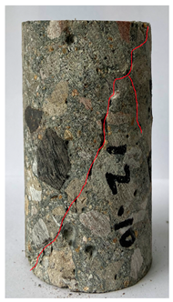 | 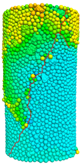 |
| 60 °C |  | 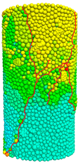 |
| 80 °C | 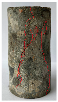 | 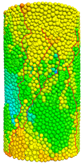 |
| Function Type | Model | Related Parameters | Concrete Type |
|---|---|---|---|
| Linear | ER: Wear erosion rate; fc: Compressive strength. | Polypropylene and steel fiber-reinforced concrete [164] | |
| fab: Wear resistance; fc: Compressive strength. | PVA fiber-reinforced concrete [162] Dam concrete mixed with iron tailings aggregates [163] | ||
| War: Wear rate; fc: Compressive strength. | Ordinary concrete [165] | ||
| D: Wear depth; t: Wear time. | Ultra-high-performance concrete [166] | ||
| Power | D: Wear depth; fc: Compressive strength. | High-strength concrete [167] | |
| War: Wear rate; vb: Flow velocity. | Steel fiber-reinforced hydraulic concrete [168] Rolled dam concrete [169] | ||
| Exponential | M1: Mass loss; fc: Compressive strength. | Ultra-high-performance concrete [166] | |
| Logarithmic | M1: Mass loss; fc: Compressive strength. | Polyester fiber fly ash concrete [170] | |
| Polynomial | M1: Mass loss; ff/t: Flexural or tensile strength. | Recycled aggregate concrete [171] | |
| D: Wear depth; fc: Compressive strength. | High-strength hydraulic concrete [158] |
Disclaimer/Publisher’s Note: The statements, opinions and data contained in all publications are solely those of the individual author(s) and contributor(s) and not of MDPI and/or the editor(s). MDPI and/or the editor(s) disclaim responsibility for any injury to people or property resulting from any ideas, methods, instructions or products referred to in the content. |
© 2025 by the authors. Licensee MDPI, Basel, Switzerland. This article is an open access article distributed under the terms and conditions of the Creative Commons Attribution (CC BY) license (https://creativecommons.org/licenses/by/4.0/).
Share and Cite
Zhu, X.; Zhou, X.; Xia, Y.; Chen, X. Performance Degradation Law and Model Construction of Hydraulic Concrete Under Freeze-Thaw Cycles: A Comprehensive Review. Buildings 2025, 15, 1596. https://doi.org/10.3390/buildings15101596
Zhu X, Zhou X, Xia Y, Chen X. Performance Degradation Law and Model Construction of Hydraulic Concrete Under Freeze-Thaw Cycles: A Comprehensive Review. Buildings. 2025; 15(10):1596. https://doi.org/10.3390/buildings15101596
Chicago/Turabian StyleZhu, Xiangyi, Xiaohe Zhou, Yuxuan Xia, and Xudong Chen. 2025. "Performance Degradation Law and Model Construction of Hydraulic Concrete Under Freeze-Thaw Cycles: A Comprehensive Review" Buildings 15, no. 10: 1596. https://doi.org/10.3390/buildings15101596
APA StyleZhu, X., Zhou, X., Xia, Y., & Chen, X. (2025). Performance Degradation Law and Model Construction of Hydraulic Concrete Under Freeze-Thaw Cycles: A Comprehensive Review. Buildings, 15(10), 1596. https://doi.org/10.3390/buildings15101596