Article

Research on the Rapid Testing Method of Influence Lines for Beam Bridges and Its Engineering Applications

1
School of Architectural Engineering, Zhengzhou Shengda University, Zhengzhou 451191, China
2
School of Civil Engineering, Zhengzhou University, Zhengzhou 450001, China
3
Henan Transportation Research Institute Co., Ltd., Zhengzhou 450015, China
*
Authors to whom correspondence should be addressed.
Buildings 2025, 15(10), 1595; https://doi.org/10.3390/buildings15101595
Submission received: 19 March 2025 / Revised: 22 April 2025 / Accepted: 6 May 2025 / Published: 9 May 2025
(This article belongs to the Section Building Structures)

Abstract

Bridges are critical nodes in transportation networks, and the evaluation of their service performance is of vital importance. Rapid assessment techniques based on the theory of influence lines have become a significant research topic. This study proposes a rapid testing method for the influence lines of beam-type bridges, with the synchronous monitoring of dynamic vehicle positions and a wireless network of multiple sensors. Field testing on a 30 m span T-beam bridge revealed that the measured vertical displacement during slow continuous driving corresponded with the static load test data within a deviation of ±6%, with the entire testing process completed in only 5 min, demonstrating efficiency and minimal traffic interference. Based on the measured influence lines, rapid bridge bearing capacity assessments and finite element model updating were researched. A case study of a simply supported T-beam bridge composed of prefabricated prestressed concrete showed that the calculated values using the proposed rapid assessment method deviated from traditional load test values between −5.68% and 4.69%, indicating a small error margin. After applying this method to the model updating of a (25 + 45 + 25) m continuous beam bridge on a highway, the inversion errors of the concrete elastic modulus and prestress were 1.40% and 1.20%, respectively, confirming the reliability of the precision. The rapid testing method for influence lines can be applied to bridge inspection, evaluation, and model updating.

1. Introduction

The evaluation of the bearing capacity of bridge structures and the analysis of their load responses are significant research topics in the field of civil engineering [1]. As key nodes in highway, railway, and urban transportation networks, beam bridges are subjected to complex dynamic loads throughout their long-term service life. The degradation of their mechanical properties directly impacts the reliability of the infrastructure system [2,3,4,5]. Influence line theory, an important tool for structural analysis, can effectively characterize the mechanical response laws of key bridge sections under moving loads. It also provides a theoretical basis for determining the most unfavorable load arrangements, identifying structural damage, and evaluating bearing capacity [6,7,8,9]. In terms of theoretical development, since Müller-Breslau proposed the construction method of the influence line based on the principle of virtual work [10], scholars have successively developed generalized influence line theory and its applications suitable for continuous beam bridges [11,12,13,14,15]. Simplified assumptions of the influence line in existing codes may lead to calculation deviations of 10% to 15%, especially in multi-span continuous beam bridges, where significant systematic errors can occur [12,16,17,18].
As bridges are critical nodes within modern transportation networks, the assessment of their structural service performance faces increasingly formidable technical challenges. Statistical data reveal that approximately 23% of global beam bridges suffer from an insufficient load-bearing capacity [19,20,21,22]. In this context, rapid evaluation technology based on influence line theory has emerged as a prominent research focus [23,24,25,26]. Xu Zheng et al. [27] introduced the development and application of bridge influence lines and presented various mathematical models for bridge influence line identification. Zhi-Wei Chen et al. [28] proposed an identification method that can automatically determine the regularization coefficient and quantify the uncertainty of identification results of bridge influence lines. Ning-Bo Wang et al. [29] proposed a numerical method for accurately extracting bridge influence lines from the dynamic responses of bridge structures and verified its feasibility and accuracy through experimental research. To achieve the rapid testing of bridge influence lines, Yu Zhou et al. [30] took the cable-stayed bridge structure as an example and proposed a method for indirectly identifying the operating modal frequencies and deflection influence lines of bridge structures from axial dynamic responses. By inferring structural characteristics such as stiffness and strength from dynamic responses to moving loads, this technology enables the rapid assessment of bridge bearing capacity, thereby enhancing the efficiency of maintenance measures and ensuring structural safety. However, dynamic effects and speed-related factors associated with actual moving loads often distort measured influence line shapes. Particularly under high-speed, heavy-duty traffic conditions, the discrepancy between the output of theoretical models and measured data can exceed 20% [31]. Moreover, obtaining accurate actual influence lines for bridge structures requires field experiments that disrupt road traffic, presenting significant challenges for bridges with high traffic volumes.
In light of the manifold challenges confronting existing bridges and the inherent limitations of traditional assessment approaches, the development of an efficient novel method for evaluating bridge bearing capacity is of utmost urgency. Against this backdrop, grounded in the theoretical analysis of influence lines, this study puts forward a rapid testing methodology for bridge structure influence lines. This methodology ingeniously integrates the synchronous monitoring of dynamic vehicle positions with the wireless networking of diverse sensors. It boasts several remarkable advantages, such as high sampling efficiency, a high degree of equipment integration, and remarkable ease of on-site operation. Leveraging the rapidly and accurately measured influence lines, this method can be effectively applied to the rapid assessment of bridge bearing capacity and the modification of finite element models.

2. Concept, Application, and Testing Methods of the Influence Line

2.1. Concept and Solution Method of the Influence Line

The influence line is a graphical tool for analyzing the mechanical effects of structures under moving loads. It is defined as a curve that shows the variation law of any response of a structure as a unit concentrated load moves on it, with the load position as the independent variable. This curve has the position of the load action as the abscissa and the value of the target mechanical quantity (the influence coefficient) generated by the unit load at the corresponding position as the ordinate. Through the superposition principle, the effect of the live load can be transformed into the sum of the products of each load value and the corresponding ordinate value of the influence line, as well as the product of the distributed load and the area of the influence line [32,33]. The sign rule of the influence line takes the direction of the unit load action as the positive direction. For example, for a horizontal member, the influence line of the gravitational load is drawn downward as positive, which essentially reflects the dynamic characteristics of the structural response during the movement of the load.
The solution methods of the influence line have evolved through the combination of classical mechanical analysis and computer numerical solutions, forming a multi-level solution system. Early research was based on the static equilibrium method [32]. By establishing equilibrium equations in a section-by-section manner, the internal force responses of statically determinate structures were calculated point by point. Although this method is intuitive, its calculation efficiency is limited. In 1886, Müller-Breslau proposed the principle of virtual displacement, transforming the solution of the influence line into the deformation curve of the structure after removing the constraints [34]. This breakthrough, systematically expounded by Hibbeler [33], has become key to dealing with statically indeterminate structures. Its essence lies in the equivalence of the energy efficiency between the load action and the virtual displacement under the principle of virtual work. With the development of matrix theory, Kassimali [35] combined the force method with the flexibility matrix and solved the distribution of redundant constraint forces through a compatibility equation, realizing the parametric expression of the influence line of complex statically indeterminate structures. In modern engineering practice, finite element numerical simulation, through discretized modeling and load traversal algorithms (such as the moving-load module in ANSYS), can efficiently solve the influence line or influence surface of structures with material nonlinearity and abrupt geometric changes. However, the verification of its accuracy still depends on classical theories.

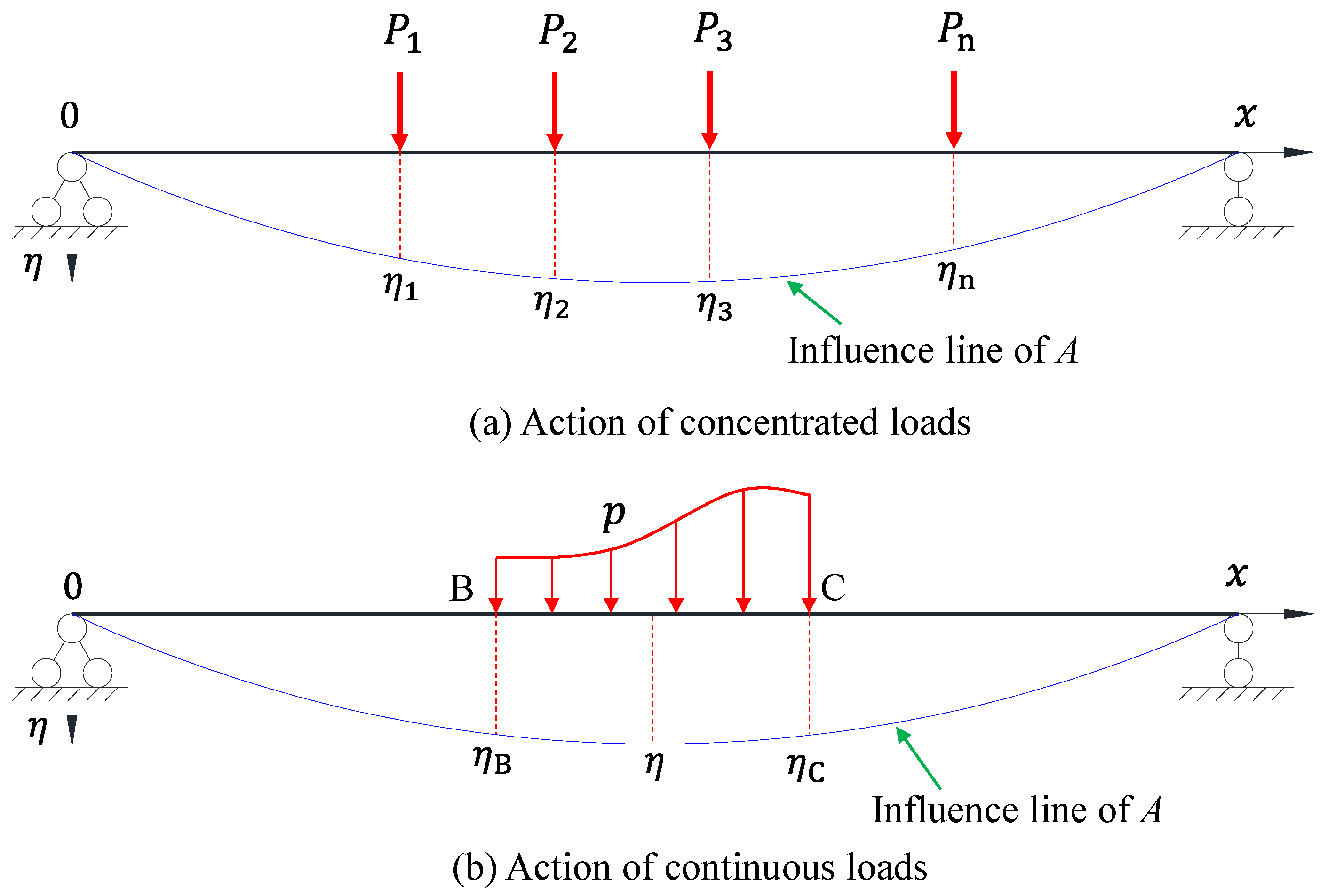
2.2. Application of the Influence Line of Beams

In engineering applications, typical curves, such as the influence lines of the internal forces and displacements of continuous-beam sections, can intuitively reveal the extreme value positions and variation laws of mechanical quantities under the action of moving loads. This provides a basis for determining the most unfavorable load conditions. It is an important method in structural mechanics for connecting the analysis of load actions and mechanical responses. As shown in the beam model in Figure 1, η represents the ordinate (the influence coefficient) of the influence line of any mechanical response when a unit concentrated load acts vertically on the beam and moves along the beam’s length direction.
In Figure 1a, under the action of concentrated loads P 1 , P 2 P n , a certain mechanical response A (such as the bending moment, shear force, axial force, displacement, or support reaction) at a certain position of the beam can be calculated using Equation (1):
A = η 1 P 1 + η 2 η P 2 + + η n P n = i = 1 n η i P i
In Figure 1b, when the structure is subjected to a continuous distributed load with an intensity of p between B and C, a certain mechanical response A at a certain position of the structure can be calculated using Equation (2):
A = B C η p d x

2.3. Methods for Testing Bridge Influence Lines

Although influence line theory provides a basic framework for evaluating the live load effect, actual bridge structures are affected by various factors during their long-term service, such as material property degradation, construction errors, and environmental changes. As a result, their mechanical responses often deviate from those of the ideal model. Therefore, measurement-based research considering the influence line has become an important part of engineering applications. By deploying equipment like strain gauges and displacement sensors and collecting the dynamic response data of target sections under the action of moving loads, the influence line of the structure can be measured in practice.
Currently, there are mainly four types of methods for testing the influence line of beam bridges: the dynamic response separation and regularization inversion method, the millimeter-wave radar multi-point synchronous testing method, the rapid detection method of the quasi-static influence line, and the computer vision fusion method [26,36,37,38,39]. The dynamic response separation and regularization inversion method utilizes Empirical Mode Decomposition (EMD) and Tikhonov regularization for data processing [15,40]. It has proven effective for simply supported beam bridges. Nevertheless, it is highly sensitive to vehicle operation conditions and likely to cause the loss of high-frequency modes. The millimeter-wave radar multi-point synchronous testing method enables the synchronous collection of deflection influence lines of multiple main girders via high-frequency sampling and can be applied for damage assessment. However, it is restricted by the alignment of the measurement points and the use of relevant algorithms. The rapid detection method of the quasi-static influence line uses a uniformly moving loading vehicle to simulate static loading and combines displacement and strain measurements, thereby shortening the detection time. Its accuracy, nonetheless, depends on the synchronism and precision of the moving vehicle and the testing instruments. The computer vision fusion method integrates a surrogate model with deep learning and is applicable to complex scenarios. However, it has high equipment costs and is limited by lighting conditions. These methods commonly encounter problems such as the insufficient suppression of dynamic interference, an excessive reliance on equipment, and a lack of uncertainty quantification. There is an urgent need to integrate multi-source data with adaptive algorithms to improve the accuracy and applicability of influence line testing.

3. Rapid Testing Method of Influence Line for Beam Bridges

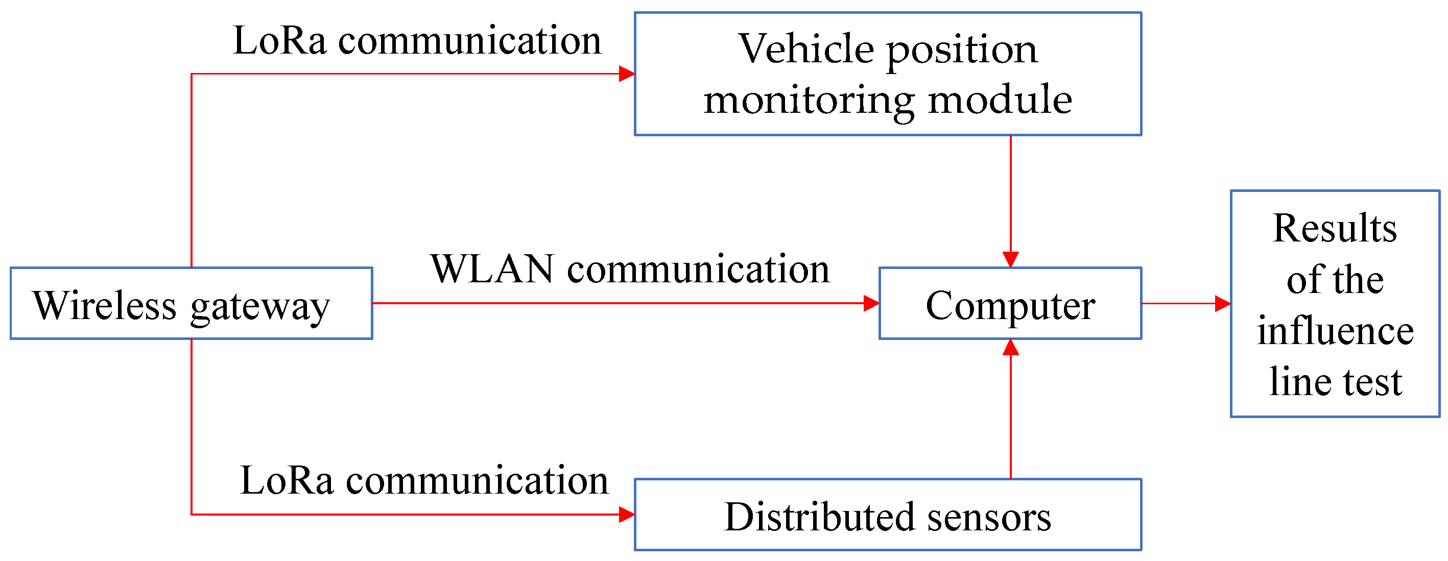
3.1. The Composition of the Testing System

Based on the rapid detection method of a quasi-static influence line, this paper proposes a rapid testing system for the influence lines of bridge structures. This system integrates the synchronous monitoring of dynamic vehicle positions with the wireless networking of multiple sensors. As shown in Figure 2, the system mainly consists of five components: a loading vehicle, vehicle position monitoring module, distributed sensor module, wireless gateway, and handheld acquisition terminal. The system also employs a sensor self-diagnosis function. When the system is started, the sensors automatically conduct a comprehensive self-check. In terms of hardware, real-time monitoring is carried out based on certain parameters, such as the voltage, current, and operating temperature of key components like the power supply circuit, signal conditioning circuit, and microcontroller. Once the parameters exceed the normal range, an alarm is triggered immediately. At the software level, the data acquisition algorithm and communication protocol stack are verified by running an internal diagnostic program to ensure that the program runs without any abnormalities.
The vehicle position monitoring module monitors the rotational speed of the wheels through a rotary encoder installed on the wheel hub. Utilizing the diameter of the wheels and the principles of circular motion, it can calculate the linear displacement of the vehicle, determine the vehicle’s position in real time, and then, in combination with a LoRa wireless communication module, upload the data to the gateway. The position monitoring module is calibrated before the test to ensure its accuracy. The selected LoRa wireless communication module operates in the 470 MHz frequency band. In an open environment, its communication distance can reach 2–5 km, meeting the long-distance data transmission requirements between sensors and the gateway in bridge testing scenarios. The communication stability of the LoRa module in a complex electromagnetic environment is of crucial importance to the testing system, especially in scenarios with strong electromagnetic interference sources such as those close to high-voltage power lines. Therefore, a continuous 24 h test was conducted on the networking system with the LoRa module in an environment close to a 110 kV high-voltage power line. The transmitting power of the module was 20 dBm, and the receiving sensitivity was −137 dBm. The test results show that, in this electromagnetic environment, the data transmission success rate of the LoRa module always remained above 97%, ensuring stable and reliable data transmission in complex electromagnetic environments.
As shown in Figure 2, distributed sensors, including high-precision displacement sensors and strain sensors, were arranged at key sections such as the mid-span, quarter-span, and supports of the bridge. Among them, the displacement sensors were arranged at the support positions to measure the settlement of the supports so as to correct the deflection of the bridge for the support settlement. The strain sensors are resistive strain gauges, which have high sensitivity and good stability and are easy to install and operate. The sensitivity of the strain gauges is 500 με/(mV/V), the maximum sampling frequency is 128 kHz, the measurement range is ±3000 με, and the working temperature ranges from −20 °C to +80 °C. For the displacement measurements, a multi-point dynamic displacement detection instrument was used. Its measurement accuracy is ±0.02 mm (at a distance of 10 m), and the maximum sampling frequency is 500 kHz. The dynamic response data of the structure were synchronously collected with high-precision displacement sensors and strain sensors to capture the structural deformation and stress changes. After signal conditioning, multi-node data aggregation was achieved through wireless networking, as shown in Figure 3.

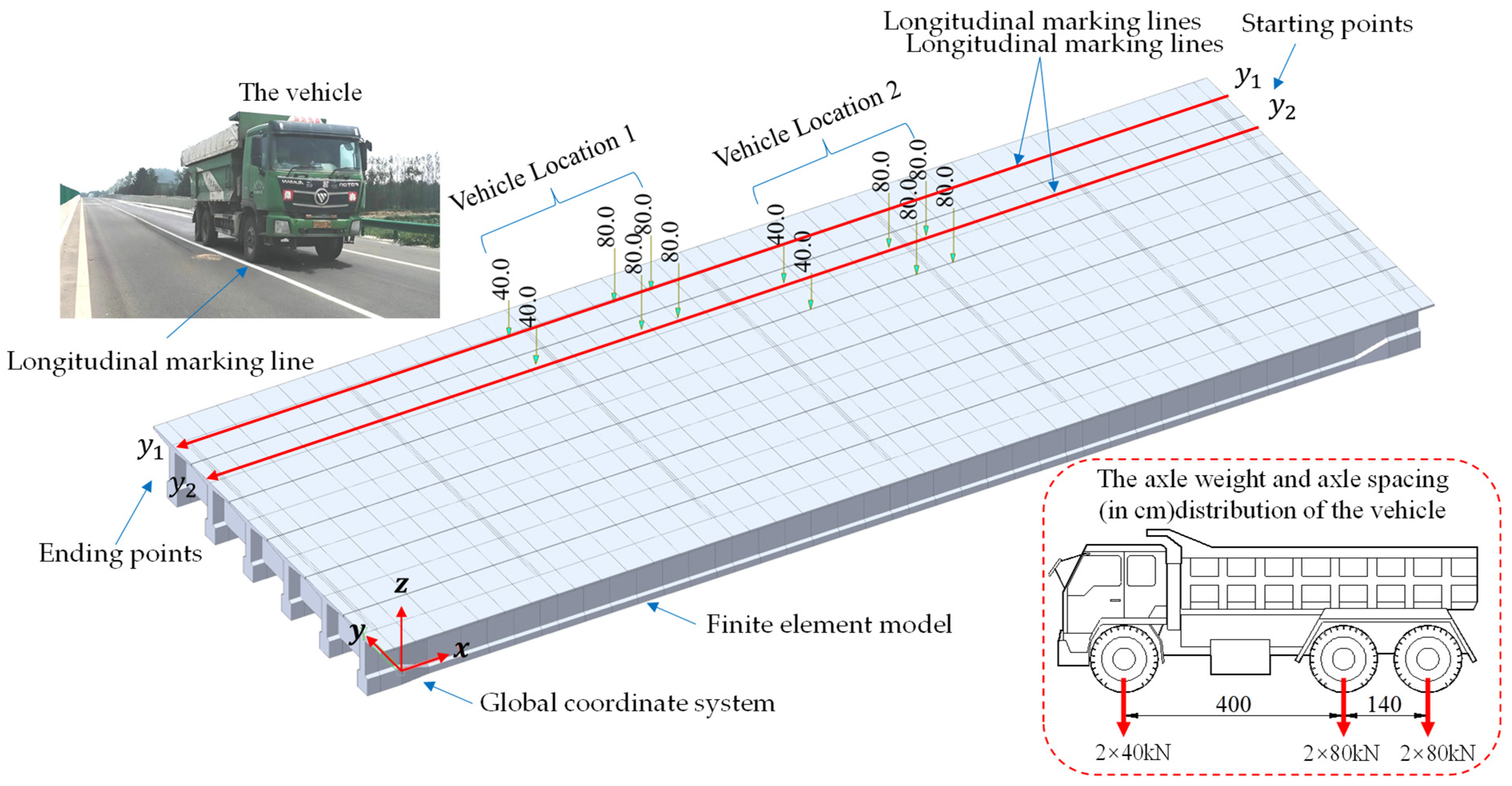
3.2. Loading Mode and Simplification of Vehicle Load

As shown in Figure 4, before the test, a global coordinate system was established, with the longitudinal direction of the bridge as the x-axis, the transverse direction as the y-axis, and the direction perpendicular to the bridge deck as the z-axis. The origin was set at a fixed point on the bridge deck, providing a reference for the load position. Before the test, longitudinal lines (along the x-axis direction) were marked at the transverse y-coordinates of the bridge (such as y 1 and y 2 in Figure 4). During the test, the vehicle traveled along the marked line (in the x-axis direction), and its transverse position remained unchanged. Therefore, only the longitudinal position (in the x-axis direction) of the vehicle needed to be recorded during a single test. Similarly, in the finite element analysis, the moving direction of the vehicle load was also defined in this way. The y-coordinate of the vehicle’s path was set for each test to represent different transverse positions. When the transverse position of the vehicle changed, the strain and deflection responses recorded by the sensors at the key positions on the beam also changed. The measured responses correlated with the transverse position of the load, and statistical analysis was carried out to establish the relationship between the load position and the structural response.
According to the provisions of the standard “Load Test Methods for Highway Bridge” [41], when conducting load tests with vehicle loading, three-axle freight vehicles are preferably used. Since the vehicle has a certain length and this length cannot be ignored in relation to the length of the bridge, the test three-axle vehicle cannot be simply regarded as a concentrated load. In static and fatigue analyses, wheel loads are often simplified as concentrated loads [42,43]. As shown in Figure 4, the three-axle vehicle is simplified and simulated as six concentrated loads; that is, each tire position is regarded as a concentrated load. During the test, the center of the right rear wheel of the vehicle is taken as the position recording point, and the positions of the loads of the remaining wheels are calculated according to the longitudinal and transverse wheelbases of the vehicle. Similarly, in the finite element model, the load of one vehicle is also simulated as six concentrated forces.

3.3. Control Measures for Test Measurement Errors

There are inevitably errors in any testing method. The main errors in the rapid testing process of the influence line mainly come from the dynamic amplification effect of the driving vehicle, the measurement errors of the instruments and equipment, and the delay errors in data collection. Therefore, it is necessary to reduce the errors in terms of controlling the driving speed, calibrating the instruments and equipment, and eliminating the delay in data collection.

3.3.1. Control of Driving Speed

When a vehicle is driving on a bridge, it will cause an impact effect of dynamic amplification. Such a dynamic effect will change the stress of the bridge and affect the accuracy of the data. Therefore, during the rapid testing process of the influence line, the vehicle speed needs to be controlled within a reasonable range. When the vehicle passes through the bridge deck at a uniform speed of ≤8 km/h, the impact effect generated by the vehicle can be ignored [43,44]. Therefore, during the test, the vehicle speed should be controlled not to exceed 8 km/h, and the vehicle should be kept running at a constant speed.

3.3.2. Calibration of Instruments and Equipment

Before the test, the rotary encoder used to measure the vehicle’s position is calibrated. First, the loading vehicle is allowed to drive slowly along a flat and straight road section of a known length, and this process is repeated at least three times. During the driving process, the number of pulses generated when the truck moves along this straight line is recorded through the rotary encoder. Then, the driving distance is calculated based on the encoder pulses, and a calibration curve between the number of encoder pulses and the actual driving distance is established through linear regression analysis. This calibration curve is used to convert the original encoder pulse data into accurate speed and displacement values during the bridge test. There is no need to calibrate the encoder separately for each bridge. It is sufficient to calibrate the rotary encoder before a group of related bridge tests. However, if there are any significant changes in the test conditions, such as changes in tire pressure, tire replacement, or vehicle replacement, the encoder needs to be recalibrated.
Before the resistive strain gauge is put into use, it should be calibrated according to relevant metrological standards to establish the corresponding relationship between the output of the strain gauge and the standard strain, ensuring that the measurement accuracy meets the requirements. Within each six-month usage cycle, at least one intermediate check should be carried out. Through comparative tests with calibrated and stable-performing strain gauges, it should be verified whether there is any drift in its measurement performance. If the strain gauge experiences extreme environmental conditions (such as exceeding the working temperature range) or is subjected to strong vibrations and impacts, it must be recalibrated before it can be used again. Similarly, before the multi-point dynamic displacement detection instrument is used, it should be calibrated with a high-precision displacement standard device to ensure the accuracy of the measurement results. The multi-point dynamic displacement detection instrument should be sent to a qualified metrological verification institution for a comprehensive verification every 12 months. Professional personnel will conduct strict tests on key performance indicators of the instrument, such as measurement accuracy and sampling frequency, in accordance with relevant verification regulations to ensure the accuracy and reliability of the measurement data.

3.3.3. Elimination of Data Delay Errors

This system eradicates the time delay difference between the vehicle movement and structural response via a spatio-temporal synchronization algorithm and actually measures the influence line with the assistance of a handheld terminal and customized software. The detailed steps of the spatio-temporal synchronization algorithm are as follows:
  • First, the rotary encoder in the vehicle position monitoring module collects real-time vehicle position information and creates a preliminary record with a timestamp. Simultaneously, the distributed sensor module collects the dynamic response data of the structure and attaches corresponding timestamps.
  • Next, the two types of data are aggregated at the gateway. With the use of the GPS time synchronization module as the main clock source, time is distributed to each sensor node through the PTP protocol to calibrate the time deviation between each sensor and the vehicle position data.
  • Then, based on the relationship between the vehicle’s driving trajectory and the position of the sensors, a spatial mapping model is constructed. Through spatial coordinate transformation, the vehicle position and structural response data collected at different times are precisely aligned in space and time.
  • Finally, the influence line is measured with the aid of the handheld terminal and customized software.

3.4. Data Collection and Processing Methods

During the data collection process, the dynamic threshold sliding window algorithm is used to judge the continuity and rationality of real-time data. Based on the mechanical characteristics of the bridge, historical monitoring data, and calculated and analyzed data, a threshold range is set for the sensor data. If a data point exceeds the threshold and the proportion of abnormal data among 10 consecutive data points exceeds 30%, the data during this period are determined to be abnormal. After confirming the abnormal data, the system adopts an interpolation algorithm based on adaptive weighted fusion to accurately correct or replace the abnormal data according to the changing trends in the preceding and following normal data points.
Each sensor module records strain and displacement data at a sampling rate of 100 Hz or greater. The gateway employs a dynamic routing protocol to calibrate the time of the multi-source data packets. Finally, within the handheld terminal, the optimal fitting curve of the discrete measured values is obtained based on the regularization algorithm. Its mathematical model can be expressed as
y = m i n x A x b 2 + α x 2
In Equation (3), A is the vehicle position matrix, where the rows correspond to the sampling moments and the columns correspond to the discrete segment positions of the bridge; b is the sensor response vector, which contains the measured values of strain/displacement; and α is the Tikhonov regularization coefficient, which controls the smoothness and noise resistance of the solution.

4. Verification of the Accuracy of the Rapid Testing of Influence Lines and Its Application Research

4.1. Verification of the Accuracy of the Rapid Testing of Influence Lines

4.1.1. Bridge Overview and Verification Method

As shown in Figure 5, the superstructure of a certain highway bridge is composed of 6 × 30 m prefabricated prestressed concrete simply supported T-beams, with six T-beams arranged transversely across the bridge. The bridge’s design load grades are Vehicle-Super 20 Grade and Trailer-120 Grade, and the pedestrian load is specified as 3.5 kN/m2.
As shown in Figure 6, the mid-span section of the first span of the structure was selected for the influence line test. A total of six strain measuring points and six displacement measuring points were placed at this mid-span section. A three-axle loading vehicle with a total weight of 400 kN was used to perform the loading operation in the lane adjacent to the sidewalk. The influence lines of the main girders were measured using two methods: the static load test method (Working Condition 1), where each section was tested sequentially, and the rapid testing method proposed in this paper (Working Condition 2). Subsequently, a comparative analysis was carried out to verify the accuracy of the rapid testing technology.
Before the test, a global coordinate system was first established, with the inner point of the sidewalk at the bridge’s starting point as the origin. At a distance of 2.5 m from the edge of the sidewalk (y = 2.5), a longitudinal line was marked along the longitudinal direction of the bridge (on the x-axis), and points were marked at intervals of 3.75 m on this line. In Working Condition 1, the calibrated loaded vehicle was driven to the positions of each marked point and stopped for loading. Subsequently, the pre-installed sensors were used to measure the strain and deflection of the main girder. Loading was carried out point by point to test the structural responses at different positions. In Working Condition 2, the loaded vehicle was guided to accurately travel along the marked line at a speed of 5 km/h. By using the sensors installed on the main girder, the strain and deflection of the main girder during the vehicle’s movement were continuously measured synchronously, and the structural responses when the vehicle load moved longitudinally were recorded.

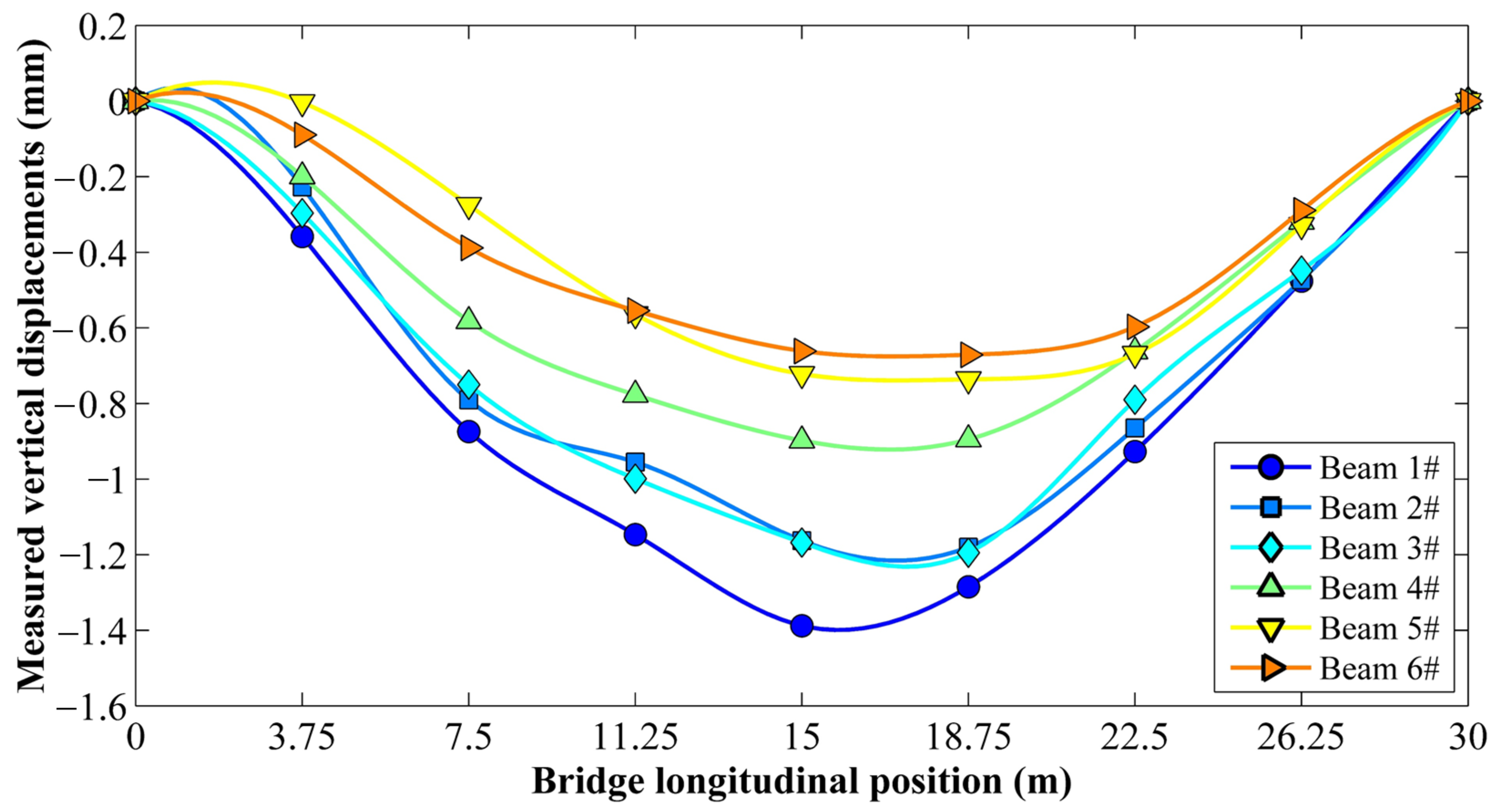
4.1.2. Analysis of the Verification Test Results

It took approximately 70 min to complete all the tests in Working Condition 1, while it only took 5 min to finish the tests in Working Condition 2. For the mid-span section of the bridge, the measured curves under Working Condition 1 and Working Condition 2 exhibited an excellent match. The peak values of the strain influence lines both occurred when the vehicles traversed the mid-span. The displacement influence lines displayed typical parabolic characteristics, and the deflection test results for the two working conditions were essentially the same.
Considering the large volume of test data, this study conducted an analysis using the measured displacement as an example. Figure 7 and Figure 8 present the measured displacements for Working Condition 1 and Working Condition 2, respectively, while Table 1 shows the measured deviations between the two working conditions. The longitudinal positions of the bridge in Figure 7 and Figure 8 and Table 1 refer to those of the right rear wheel of the vehicle along the bridge.
The data comparison and deviation analysis indicate that the vertical displacements measured using the rapid influence line testing method are in close agreement with those obtained using the static load test method. All measured deviations are within ±6%. Considering the actual engineering application scenarios and testing purposes comprehensively, the measured deviation within ±6% is completely acceptable. The proposed rapid influence line test requires only 5 min for a 30 m span beam bridge, providing an efficient and low-interference on-site solution for determining the actual influence line of a bridge.

4.2. Rapid Evaluation of Bridge Bearing Capacity Based on the Measured Influence Lines

4.2.1. Methods and Steps for Bearing Capacity Assessment

In assessments of bridge bearing capacity, displacement and strain are frequently employed as detection indices. The actual influence lines are measured by running a single vehicle load either once or multiple times. Subsequently, the strain and displacement of the structure under the design load are computed utilizing the actual influence lines, and the bearing capacity is evaluated in accordance with relevant specifications. For prefabricated bridges, during the influence line test, a slow-running vehicle test is generally conducted lane by lane. Each group of tests yields a set of influence lines, whereas the traditional load test typically uses two or more trains for loading. Therefore, when evaluating the bridge bearing capacity according to the checking calculation method, it is essential to take into account the combination of influence line test working conditions.
The main implementation steps for the rapid evaluation of the bridge bearing capacity based on the measured influence lines are as follows:
  • Conduct a rapid test on beam bridges, and measure the strain and displacement influence lines of each measuring point in the control section. Multiple tests can be carried out according to the lateral lane position of the vehicle.
  • As depicted in Figure 9, position the test load of the static load test on the measured influence lines, and obtain the static load–test load response according to Equation (4).
    w = P i η i
  • Combine the loading working conditions during the traditional load test based on multiple loading tests, superimpose and calculate the measured values of each beam, and use the ratio in the theoretical calculation to represent the structural calibration coefficient η.
  • Evaluate the bearing capacity of the bridge in line with relevant specifications [41,45,46].

4.2.2. Case Analysis of Rapid Assessment of Bearing Capacity

As an illustrative example, the first span of the 6 × 30 m prefabricated prestressed concrete simply supported T-beam bridge described in Section 4.1.1 was chosen. The rapid assessment method based on the measured influence line and the traditional load testing approach were compared to verify the feasibility of the former. Focusing on the vertical displacement at the mid-span cross-section of the bridge, the displacement values calculated from the measured influence line were compared with the measured values under the corresponding working conditions of the load test, and the results are shown in Table 2.
The data analysis in Table 2 shows that the deviation is minimal between the calculated values obtained using the rapid assessment method and the measured values from the traditional load test, ranging from −5.68% to 4.69%. This finding demonstrates the reliability of the rapid assessment method, suggesting that it can, to a certain extent, replace the traditional load test. Moreover, the calibration coefficients of the rapid assessment method are similar to those of the traditional load test. This indicates that both methods produce comparable results when evaluating the degree of structural response, thus validating the applicability of the rapid assessment method for bridge bearing capacity evaluation.
Compared with the traditional load test, the proposed rapid bearing capacity assessment method has significant advantages. Regarding impact on traffic, the traditional test requires 2 to 3 h of traffic control, which seriously affects traffic flow. By comparison, the rapid method requires no more than 10 min of traffic control for a single test, greatly reducing the impact on the bridge’s traffic. In terms of economy, the traditional test incurs high costs for equipment leasing and labor, as well as indirect costs due to traffic control. The rapid method features the use of simple equipment, low manpower requirements, and no additional expenses for traffic control, with the cost being only about 30% of that of the traditional method.

4.3. Finite Element Model Updating of Bridges Using Measured Influence Lines

4.3.1. Methods and Steps of Model Correction

For the finite element model’s updating based on measured influence lines, the actual measured influence lines are mainly employed as benchmarks. By adjusting the model parameters, a benchmark model that can accurately reflect the actual structural conditions to the greatest extent possible is obtained. Model updating takes the measured influence line data as its core. Through the iterative optimization of model parameters, a benchmark model that conforms to the actual mechanical behavior of the bridge is established. Compared with traditional dynamic characteristic updating methods (such as those based on frequency and mode shape updating), the influence line method is more sensitive to local stiffness degradation and is particularly suitable for identifying bearing capacity losses caused by issues like main girder cracking and bearing settlement [47,48,49].
The core steps of updating bridge models based on measured influence lines are as follows:
  • Influence line measurement: The actual influence lines of beam bridges are rapidly measured by running a single vehicle load either once or multiple times, and the displacement and strain influence line data of key cross-sections of the main girder are collected.
  • Initial model establishment: A finite element model is constructed according to the design drawings and material parameters. The parameters to be updated, such as the elastic modulus, prestress loss, and boundary conditions, are set, and a calculation analysis is conducted to solve the influence lines of the initial finite element simulation.
  • Objective function construction: The root mean square error (RMSE) between the measured and simulated influence lines is defined as the optimization objective, with the following equation:
    R M S E = 1 n i = 1 n   η measured i η simulated i 2
  • Iterative update analysis: The Sobol index is utilized to screen sensitive parameters [50], and intelligent optimization algorithms are employed to iteratively update key parameters, such as the elastic modulus and prestress loss, until the shape error of the influence lines calculated with the finite element method converges within the threshold range.

4.3.2. Case Analysis of Continuous Beam Bridge Model Updating

A three-span prestressed concrete continuous beam bridge on a certain expressway was completed in 2006. Its span arrangement is (25 + 45 + 25) m. The main girder is a variable cross-section box girder constructed with C50 concrete. The bridge model was established using Midas/Civil 2021 finite element software.
As depicted in Figure 10, an influence line test was conducted with a three-axle loading vehicle weighing a total of 400 kN moving at a constant speed of 5 km/h. A total of nine displacement measuring points and nine strain measuring points were set up at the key cross-sections (mid-span and quarter-span) of the main girder. The data acquisition frequency was 100 Hz. During the test, the displacement and strain influence lines under the action of the moving load were synchronously recorded for model updating.
The parameters of the bridge model were updated using the measured influence lines. The updated data results are presented in Table 3, where the relative error is calculated as follows: ∣(updated value − measured value)/measured value∣ ×100%. The theoretical elastic modulus of C50 concrete is 34.5 GPa; considering the long-term modulus growth of concrete, the initial value of the elastic modulus was set to 45.0 GPa, which is 1.3 times the theoretical value [51,52]. The updated value of the elastic modulus was 42.5 GPa, with an error of 1.4% relative to the measured value of 43.1 GPa obtained using the core-drilling method. This indicates the reliable accuracy of model inversion. To measure the elastic modulus of concrete with the core-drilling method, a total of six core samples with a diameter of 100 mm were drilled at the mid-span, quarter-span, and support positions of the bridge’s main girder. After end-face grinding treatment, a 2000 kN press was used to load at a rate of 0.5 MPa/s. In combination with biaxial strain gauges, the secant modulus under 40% of the ultimate load was measured, and the average value of the elastic modulus was obtained as 43.1 GPa.
The initial model does not consider the prestress loss. The revised value after the prestress loss is 0.85, corresponding to a 15% prestress loss. The transverse tensioning method is used to test the three external tendons of the bridge, and the average value of the prestress effective coefficient obtained is 0.87. The revised coefficient is basically in line with the effective coefficient of 0.87 after the measured loss. It is challenging to directly measure the bearing stiffness on site. The updated value of the bearing stiffness is 0.93 × 10⁶ N/mm, indicating that the stiffness degradation of the bearing rubber (7% lower than the design value) is consistent with the cracking phenomenon of the bearing observed during visual inspection.
The data analysis results of model updating using the measured influence lines indicate that the error between the updated value of the elastic modulus and the value measured with the core-drilling method is merely 1.4%. The updated value of the prestress loss is essentially consistent with the construction period records, and the updated value of the bearing stiffness also agrees with the aging condition caused by bearing cracking. This fully demonstrates the reliable inversion accuracy of the model parameters. This method exhibits higher damage identification accuracy than traditional dynamic updating methods and provides a reliable benchmark model for bridge bearing capacity assessment and health monitoring.

5. Conclusions

This study focused on the influence lines of bridge structures. Based on the concepts of influence lines, solution methods, and application methods for beams, this study compared existing bridge influence line testing methods and proposed a rapid testing technology based on the synchronous monitoring of dynamic vehicle positions and the wireless networking of multiple sensors. The influence lines obtained via rapid testing were used for the rapid assessment of the bearing capacity and model correction of continuous beam bridges. This study’s conclusions are as follows:
  • The proposed rapid testing system for bridge influence lines only took 5 min in a test with a 30 m span T-beam bridge. The vertical displacements measured with this method are basically consistent with the test data of the static load test method, and the measured deviations are all within ±6%. It provides an efficient and low-interference on-site solution for determining actual influence lines.
  • In comparing the traditional load test with the rapid bridge bearing capacity assessment based on measured influence lines, the deviation between the calculated values of the rapid assessment and the test values of the traditional load test is between −5.68% and 4.69%. The calibration coefficients of both methods are close, indicating that this rapid assessment method is reliable and can, to a certain extent, replace the traditional load test for bridge bearing capacity evaluation.
  • The rapid influence line testing and rapid bearing capacity assessment method proposed in this study has obvious advantages in terms of efficiency and economy. This method can quickly screen and assess the bearing capacity of multiple bridges in a short period of time, significantly improving the efficiency of bridge cluster management and saving costs. For bridges where traffic closure is not possible, this method enables inspection and assessment with minimal interference to traffic, which is practical in real-world scenarios.
  • Taking a three-span prestressed concrete continuous beam bridge on an expressway as an example, for the model correction method based on the measured influence lines of continuous beam bridges, the error between the corrected value of the elastic modulus and the value measured with the core-drilling method is only 1.4%. The corrected value of the prestress loss basically coincides with the records during the construction period, and the corrected value of the bearing stiffness also conforms to the aging condition presented by the bearing cracking. This shows that this method has higher damage identification accuracy than the traditional dynamic correction method and provides a reliable benchmark model for bridge bearing capacity assessment and health monitoring.
The influence line testing and rapid bearing capacity assessment method proposed in this study has obvious advantages in terms of efficiency and economy, but there are limitations in its applicable conditions. This method is only applicable to beam bridges and is not suitable for other bridge types, such as suspension bridges and cable-stayed bridges. This study only conducted testing and research on prefabricated T-beam bridges and continuous box girder bridges. Although these bridges are representative to a certain extent, it is still necessary to carry out tests on more types of beam bridges to verify the effectiveness of the method. In addition, a more in-depth study of the influence of dynamic loads should be carried out. By constructing accurate mechanical models and applying advanced sensing and analysis technologies, the reliability and universality of the assessment method under complex working conditions can be improved, providing more scientific support to bridge safety inspection and maintenance.

Author Contributions

Conceptualization, H.L. and X.T.; methodology, J.L.; software, H.L. and X.T.; validation, P.Y. and J.Z.; formal analysis, H.L.; investigation, H.L., J.Z., and X.T.; resources, J.L.; data curation, H.L.; writing—original draft preparation, H.L. and X.T.; writing—review and editing, J.L.; visualization, X.T.; supervision, J.L.; project administration, X.T. and P.Y.; funding acquisition, H.L. and J.L. All authors have read and agreed to the published version of the manuscript.

Funding

This research was funded by the Transportation Science and Technology Planning Project of Henan Province, China (Grant No. 2021J2 and Grant No. 2015X01-2); the Henan Province Major Science and Technology Project, China (Grant No. 151100310900); and the Science and Technology Planning Project of Henan Construction Science and Technology Association, namely, “Research on the Development and Application of Bridge Influence Line Testing Technology”.

Data Availability Statement

All data, models, and code generated or used in this study are available from the corresponding author upon request.

Conflicts of Interest

Author Haikuan Liu was employed by the company Henan Transportation Research Institute Co., Ltd. The remaining authors declare that the research was conducted in the absence of any commercial or financial relationships that could be construed as a potential conflict of interest.

References

  1. Editorial Department of China Journal of Highway and Transport. Review on China’s Bridge Engineering Research: 2024. China J. Highw. Transp. 2024, 37, 1–160. [Google Scholar] [CrossRef]
  2. Liu, Y.J.; Liu, J.; Zhou, X.H.; Wang, Z.; Meng, J.M.; Zhao, X.D.; Yang, J.; Michel, G. Review on Long-Life Design Theory for Bridges. J. Transp. Eng. 2024, 24, 1–24. [Google Scholar] [CrossRef]
  3. Avci, O.; Abdeljaber, O.; Kiranyaz, S.; Hussein, M.; Gabbouj, M.; Inman, D.J. A Review of Vibration-Based Damage Detection in Civil Structures: From Traditional Methods to Machine Learning and Deep Learning Applications. Mech. Syst. Signal Process. 2021, 147, 107077. [Google Scholar] [CrossRef]
  4. Zhang, J.; Cheung, M.M.S. Modeling of Chloride-Induced Corrosion in Reinforced Concrete Structures. Mater. Struct. 2012, 46, 573–586. [Google Scholar] [CrossRef]
  5. Lee, Y.-J.; Cho, S. SHM-Based Probabilistic Fatigue Life Prediction for Bridges Based on FE Model Updating. Sensors 2016, 16, 317. [Google Scholar] [CrossRef] [PubMed]
  6. He, S.H.; Zhao, X.M.; Ma, J.; Zhao, Y.; Song, H.S.; Song, H.X.; Song, H.X.; Cheng, L.; Yuan, Z.Y.; Huang, F.W.; et al. Review of Highway Bridge Inspection and Condition Assessment. China J. Highw. Transp. 2017, 30, 63–80. [Google Scholar] [CrossRef]
  7. Zhou, Y.J.; Zhao, Y.; Zhao, Y.; Cao, Q.; Li, Z. A Study on Dynamic Load Allowanee of a Simply Supported Girder Bridge Based on Load Efficiency of a Dynamic Load Test. J. Vib. Shock 2021, 40, 207–216. [Google Scholar] [CrossRef]
  8. Deng, L.; Wu, H.; He, W.; Ling, T.; Liu, G. Genuine Influence Line and Influence Surface Identification from Measured Bridge Response Considering Vehicular Wheel Loads. J. Bridg. Eng. 2023, 28, 04022145. [Google Scholar] [CrossRef]
  9. Zheng, X.; Yi, T.-H.; Yang, D.-H.; Li, H.-N.; Zhou, Y. Bridge Evaluation Based on Identified Influence Lines and Influence Surfaces: Multiple-Scenario Application. Int. J. Struct. Stab. Dyn. 2023, 23, 2340026. [Google Scholar] [CrossRef]
  10. Kurrer, K. The History of the Theory of Structures: Searching for Equilibrium; Wiley: Hoboken, NJ, USA, 2018. [Google Scholar]
  11. Zhan, J.W.; Gao, S.X.; Zhang, F.; Liang, Z.G.; Yan, Y.Z. Damage Evaluation Method for Hinged Joints in Slab-Girder Bridges Using Online Dynamic Responses. China J. Highw. Transp. 2018, 31, 156–166. [Google Scholar]
  12. Chaudhary, M.T.A.; Morgese, M.; Taylor, T.; Ansari, F. Method and Application for Influence-Line-Free Distributed Detection of Gross Vehicle Weights in Bridges. Structures 2025, 73, 108298. [Google Scholar] [CrossRef]
  13. Yin, T.H.; Zheng, X.; Yang, D.H.; Li, H.N. Research Advances on Load-Carrying Capacity Evaluation Technology of Highway Bridges. China J. Highw. Transp. 2025, 38, 129–143. [Google Scholar] [CrossRef]
  14. Chen, Z.; Yang, W.; Li, J.; Yi, T.; Wu, J.; Wang, D. Bridge Influence Line Identification Based on Adaptive B-spline Basis Dictionary and Sparse Regularization. Struct. Control Health Monit. 2019, 26, e2355. [Google Scholar] [CrossRef]
  15. Zheng, X.; Yang, D.; Yi, T.; Li, H. Bridge Influence Line Identification from Structural Dynamic Responses Induced by a High-speed Vehicle. Struct. Control Health Monit. 2020, 27, e2544. [Google Scholar] [CrossRef]
  16. Pacheco, J.N.; de Brito, J.; Chastre, C.; Evangelista, L. Bond of Recycled Coarse Aggregate Concrete: Model Uncertainty and Reliability-Based Calibration of Design Equations. Eng. Struct. 2021, 239, 112290. [Google Scholar] [CrossRef]
  17. Cao, R.; Agrawal, A.K.; El-Tawil, S.; Xu, X.; Wong, W. Performance-Based Design Framework for Bridge Piers Subjected to Truck Collision. J. Bridg. Eng. 2019, 24, 04019064. [Google Scholar] [CrossRef]
  18. Breccolotti, M.; Natalicchi, M. Bridge Damage Detection Through Combined Quasi-Static Influence Lines and Weigh-in-Motion Devices. Int. J. Civ. Eng. 2021, 20, 487–500. [Google Scholar] [CrossRef]
  19. Orcesi, A.; Boros, V.; Kušter Marić, M.; Mandić Ivanković, A.; Sýkora, M.; Caspeele, R.; Köhler, J.; O’Connor, A.; Schmidt, F.; Di Bernardo, S.; et al. Bridge Case Studies on the Assignment of Partial Safety Factors for the Assessment of Existing Structures; Springer International Publishing: Berlin/Heidelberg, Germany, 2021; pp. 205–218. [Google Scholar]
  20. Xia, P.-Q.; Brownjohn, J.M.W. Bridge Structural Condition Assessment Using Systematically Validated Finite-Element Model. J. Bridg. Eng. 2004, 9, 418–423. [Google Scholar] [CrossRef]
  21. Enid Teresa, A.R.; Umarani, G.; Kanchanadevi, A. Load Rating of Bridges—Current Practices and Issues. Appl. Technol. Innov. 2010, 2, 9–18. [Google Scholar] [CrossRef]
  22. Helmerich, R.; Niederleithinger, E.; Algernon, D.; Streicher, D.; Wiggenhauser, H. Bridge Inspection and Condition Assessment in Europe. Transp. Res. Rec. J. Transp. Res. Board 2008, 2044, 31–38. [Google Scholar] [CrossRef]
  23. Zheng, X. Stiffness and Load-Carrying Capacity Evaluations of Short-andMedium Span Bridges Based on Influence Coefficients. Ph.D. Thesis, Dalian University of Technology, Dalian, China, 2022. [Google Scholar]
  24. Zhou, Y.; Shang, W.Q.; Di, S.K.; Zheng, X.; He, W.Y. Test Study on Influence Line Identification and Load-Bearing Capacity Rapidevaluation for Continuous Girder Bridge. Vib. Shock 2024, 43, 334–344. [Google Scholar] [CrossRef]
  25. Zhang, G. Bridge Distributed Stiffness Identification Based on Microwave Interferometric Radar Technology and Influence Line Theory. Ph.D. Thesis, Southeast University, Nanjing, China, 2023. [Google Scholar]
  26. Wang, N.-B.; Shen, W.; Guo, C.; Wan, H.-P. Moving Load Test-Based Rapid Bridge Capacity Evaluation through Actual Influence Line. Eng. Struct. 2022, 252, 113630. [Google Scholar] [CrossRef]
  27. Zheng, X.; Yang, D.-H.; Yi, T.-H.; Li, H.-N. Development of Bridge Influence Line Identification Methods Based on Direct Measurement Data: A Comprehensive Review and Comparison. Eng. Struct. 2019, 198, 109539. [Google Scholar] [CrossRef]
  28. Chen, Z.; Zhao, L.; Yan, W.; Yuen, K.; Wu, C. A Statistical Influence Line Identification Method Using Bayesian Regularization and a Polynomial Interpolating Function. Struct. Control Health Monit. 2022, 29, e3080. [Google Scholar] [CrossRef]
  29. Wang, N.-B.; Wang, C.; Zhou, H.; Zuo, Q. A Novel Extraction Method for the Actual Influence Line of Bridge Structures. J. Sound Vib. 2023, 553, 117605. [Google Scholar] [CrossRef]
  30. Zhou, Y.; Shi, Y.; Di, S.; Han, S.; Wang, J. Research on Indirect Influence-Line Identification Methods in the Dynamic Response of Vehicles Crossing Bridges. Appl. Sci. 2024, 14, 7821. [Google Scholar] [CrossRef]
  31. Kim, J.; Lynch, J.P. Experimental Analysis of Vehicle–Bridge Interaction Using a Wireless Monitoring System and a Two-Stage System Identification Technique. Mech. Syst. Signal Process. 2012, 28, 3–19. [Google Scholar] [CrossRef]
  32. Timoshenko, S.P.; Young, D.H. Theory of Structures; McGraw-Hill: New York, NY, USA, 1965; pp. 223–230. [Google Scholar]
  33. Hibbeler, R.C. Structural Analysis; Prentice Hall: Hoboken, NJ, USA, 2012; pp. 298–305. [Google Scholar]
  34. Müller-Breslau, H.F.B. Graphical Statics of Building Structures; Wilhelm Engelmann: Leipzig, Germany, 1886. [Google Scholar]
  35. Kassimali, A. Structural Analysis; Cengage Learning: Singapore, 2014; pp. 451–470. [Google Scholar]
  36. Jian, X.; Xia, Y.; Sun, S.; Sun, L. Integrating Bridge Influence Surface and Computer Vision for Bridge Weigh-in-motion in Complicated Traffic Scenarios. Struct. Control Health Monit. 2022, 29, e3066. [Google Scholar] [CrossRef]
  37. Zhou, Y.; Zhou, S.; Hao, G.; Zhang, J. Bridge Influence Line Identification Based on Big Data and Interval Analysis with Affine Arithmetic. Measurement 2021, 183, 109807. [Google Scholar] [CrossRef]
  38. Dan, D.; Kong, Z. Bridge Vehicle-Induced Effect Influence Line Characteristic Function Based on Monitoring Big Data: Definition and Identification. Struct. Health Monit. 2022, 22, 2987–3005. [Google Scholar] [CrossRef]
  39. Ge, L.; Koo, K.Y.; Wang, M.; Brownjohn, J.; Dan, D. Bridge Damage Detection Using Precise Vision-Based Displacement Influence Lines and Weigh-in-Motion Devices: Experimental Validation. Eng. Struct. 2023, 288, 116185. [Google Scholar] [CrossRef]
  40. Zhou, Y.; Shang, W.Q.; Wu, D.Y.; Di, S.K.; Zheng, X. Influence Line Identification Method of Beam Bridge Based on Empiricalmode Decomposition and Tikhonov Regularization. J. Vib. Eng. 2025, 38, 144–153. [Google Scholar] [CrossRef]
  41. JTG/T J21-01-2015; Load Test Methods for Highway Bridge. Ministry of Transport of the People’s Republic of China: Beijing, China, 2015.
  42. JTG D60-2015; General Specifications for Design of Highway Bridges and Culverts. Ministry of Transport of the People’s Republic of China: Beijing, China, 2015.
  43. American Association of State Highway and Transportation Officials. AASHTO LRFD Bridge Design Specifications; American Association of State Highway and Transportation Officials (AASHTO): Washington, DC, USA, 2024; Available online: https://trid.trb.org/View/2508889 (accessed on 18 March 2025).
  44. Qian, J.; Chen, L.; Sun, J.-Q. Transient Response Prediction of Randomly Excited Vibro-Impact Systems via RBF Neural Networks. J. Sound Vib. 2022, 546, 117456. [Google Scholar] [CrossRef]
  45. CJJ/T 233-2015; Technical Code for Test and Evaluation of City Bridges. SAC (Standardization Administration of the People’s Republic of China): Beijing, China, 2015.
  46. JTG/T J21—2011; Specification for Inspection and Evaluation of Load-Bearing Capacity of Highway Bridges. Ministry of Transport of the People’s Republic of China: Beijing, China, 2011.
  47. Guan, Z.-X.; Yang, D.-H.; Yi, T.-H.; Li, W.-J.; Li, C. Bridge Finite Element Model Updating Using Stochastic Vehicle-Induced Static Response Monitoring Data. Eng. Struct. 2023, 301, 117280. [Google Scholar] [CrossRef]
  48. Chen, Z.-W.; Cai, Q.-L.; Zhu, S. Damage Quantification of Beam Structures Using Deflection Influence Lines. Struct. Control Health Monit. 2018, 25, e2242. [Google Scholar] [CrossRef]
  49. Zhu, X.Q.; Law, S.S. Damage Detection in Simply Supported Concrete Bridge Structure Under Moving Vehicular Loads. J. Vib. Acoust. 2007, 129, 58–65. [Google Scholar] [CrossRef]
  50. Jaishi, B.; Ren, W.-X. Structural Finite Element Model Updating Using Ambient Vibration Test Results. J. Struct. Eng. 2005, 131, 617–628. [Google Scholar] [CrossRef]
  51. ACI Committee 363; State-of-the-Art Report on High-Strength Concrete. American Concrete Institute: Farmington Hills, MI, USA, 1992. Available online: https://www.silicafume.org/pdf/reprints-363rtoc.pdf (accessed on 18 March 2025).
  52. Neville, A.M. Properties of Concrete; Pearson: Essex, UK, 2011. [Google Scholar]
Figure 1. Schematic of the mechanical response of the influence line of the beam.
Buildings 15 01595 g001
Figure 2. Rapid testing system for bridge influence line.
Buildings 15 01595 g002
Figure 3. Diagram of the transmission and collection of test data.
Buildings 15 01595 g003
Figure 4. Bridge finite element model and vehicle loading diagram.
Buildings 15 01595 g004
Figure 5. Bridge photos.
Buildings 15 01595 g005
Figure 6. Strain/displacement measuring points at the mid-span and the test vehicle.
Buildings 15 01595 g006
Figure 7. Vertical displacements of each beam under Working Condition 1.
Buildings 15 01595 g007
Figure 8. Vertical displacements of each beam under Working Condition 2.
Buildings 15 01595 g008
Figure 9. Vehicle loading diagram based on the measured influence line.
Buildings 15 01595 g009
Figure 10. Schematic of the finite element model and the experimental test.
Buildings 15 01595 g010
Table 1. Measured deviation between Working Condition 2 and Working Condition 1.
Bridge Longitudinal Position (m)Measured Deviation Between Working Condition 2 and Working Condition 1
1#2#3#4#5#6#
0000000
3.752.58%−1.73%4.59%0.00%−3.86%−5.32%
7.5−3.74%0.38%−2.09%−4.18%1.04%−0.77%
11.25−4.34%−2.95%−2.73%1.26%−2.26%−2.46%
151.31%−2.68%−5.19%−3.22%−4.47%0.00%
18.75−2.21%−0.92%−3.24%−4.29%−4.58%−1.61%
22.5−0.64%−3.78%−5.95%−2.48%0.76%4.55%
26.25−4.03%−5.96%−3.86%3.47%−5.90%−2.69%
30000000
Table 2. Comparison of data between rapid evaluation based on influence line and traditional load test.
Beam NumberDisplacement Test Results and DeviationsTheoretical Displacement Values and Calibration
Coefficients
Rapid Evaluation (mm)Traditional Load Test (mm)DeviationTheoretical
Displacement Value (mm)
Calibration
Coefficient of Rapid Evaluation Method
Calibration
Coefficient of
Traditional Load Test
1#−2.79−2.87−2.79%−8.390.330.34
2#−2.99−3.17−5.68%−8.870.340.36
3#−3.82−3.97−3.78%−9.210.410.43
4#−3.89−4.06−4.19%−9.210.420.44
5#−4.24−4.054.69%−8.870.480.46
6#−3.62−3.78−4.23%−8.390.430.45
Table 3. Comparison of model parameter updating results.
Model ParameterInitial ValueUpdated ValueMeasured Verification ValueRelative Error
Elastic modulus of concrete45.0 GPa42.5 GPa43.1 GPa1.40%
Prestress loss coefficient1.0 (No Loss)0.850.871.20%
Bearing stiffness1.0 × 10⁶ N/mm0.93 × 10⁶ N/mm//
Disclaimer/Publisher’s Note: The statements, opinions and data contained in all publications are solely those of the individual author(s) and contributor(s) and not of MDPI and/or the editor(s). MDPI and/or the editor(s) disclaim responsibility for any injury to people or property resulting from any ideas, methods, instructions or products referred to in the content.

