Article

Research on Automated On-Site Construction of Timber Structures: Mobile Construction Platform Guided by Real-Time Visual Positioning System

1
iSMART, Qingdao University of Technology, Qingdao 266033, China
2
Faculty of Environmental Engineering, The University of Kitakyushu, Fukuoka 808-0135, Japan
3
School of Architecture, Tianjin Chengjian University, Tianjin 300074, China
4
College of Architecture & the Built Environment, Thomas Jefferson University, Philadelphia, PA 19144, USA
*
Authors to whom correspondence should be addressed.
Buildings 2025, 15(10), 1594; https://doi.org/10.3390/buildings15101594
Submission received: 26 March 2025 / Revised: 1 May 2025 / Accepted: 7 May 2025 / Published: 8 May 2025

Abstract

:
In recent years, the AEC industry has increasingly sought sustainable solutions to enhance productivity and reduce environmental pollution, with wood emerging as a key renewable material due to its excellent carbon sequestration capability and low ecological footprint. Despite significant advances in digital fabrication technologies for timber construction, on-site assembly still predominantly relies on manual operations, thereby limiting efficiency and precision. To address this challenge, this study proposes an automated on-site timber construction process that integrates a mobile construction platform (MCP), a fiducial marker system (FMS) and a UWB/IMU integrated navigation system. By deconstructing traditional modular stacking methods and iteratively developing the process in a controlled laboratory environment, the authors formalize raw construction experience into an effective workflow, supplemented by a self-feedback error correction system to achieve precise, real-time end-effector positioning. Extensive experimental results demonstrate that the system consistently achieves millimeter-level positioning accuracy across all test scenarios, with translational errors of approximately 1 mm and an average repeat positioning precision of up to 0.08 mm, thereby aligning with on-site timber construction requirements. These findings validate the method’s technical reliability, robustness and practical applicability, laying a solid foundation for a smooth transition from laboratory trials to large-scale on-site timber construction.

1. Introduction

In recent years, the construction industry has faced significant challenges in improving productivity and addressing environmental pollution. Specifically, construction-related activities currently account for approximately 38% of global energy-related CO2 emissions, reaching historical highs [1]. Consequently, exploring more sustainable and environmentally friendly construction materials and technologies has become a global research priority. As a renewable material, wood has emerged as a critical solution to ecological challenges in construction due to its excellent carbon sequestration capability, lower ecological footprint and the ability to reduce dependence on non-renewable resources [2,3,4,5]. Taking the widely used cross-laminated timber (CLT) material as an example, meta-analyses covering 2019–2024 place its embodied-carbon intensity at 100–250 kg CO2e m−2, approximately 40–75% lower than reinforced-concrete slabs (250–450 kg CO2e m−2) and 25–50% lower than steel frames (350–600 kg CO2e m−2) [6,7]. The inclusion of ≈0.7 t CO2 m−3 of biogenic carbon sequestered in wood can push whole-life global warming potential reductions toward 90% relative to concrete [8]. CLT construction also reduces on-site energy, noise and waste while delivering health benefits associated with exposed timber interiors. By contrast, structural steel offers superior durability and closed-loop recyclability (>95%), and low-carbon concretes using limestone-calcined-clay blends can cut cement-related emissions by ~40% [9,10]. The forthcoming hydrogen-direct-reduced steel may achieve 80% lower emissions; yet, it remains pre-commercial [11]. Hence, CLT—alone or in hybrid floor-plate/low-carbon-core configurations—currently provides the most practical pathway to deep embodied-carbon mitigation in mid-rise buildings.
Although the inherent instability of traditional natural wood materials previously limited their widespread application, these issues have been significantly mitigated through rapid advancements in computer-aided design and manufacturing (CAD/CAM), CNC machining and robotic fabrication technologies. These developments have rendered timber construction one of the most mature sectors for digital technology applications in the construction industry [12].
However, on-site assembly of timber structures is still predominantly manual, with limited integration of digital technologies into field operations, thereby restricting further improvements in construction efficiency [13]. To overcome the spatial and flexibility constraints of traditional stationary CNC equipment, robotic technologies have increasingly gained prominence in timber construction. Robots can directly utilize digital design data to perform precise, rapid and flexible construction operations, thus effectively promoting the automated assembly of non-standard timber components [13]. In particular, advancements in robotics have led to growing applications of mobile robotic systems on construction sites, aiming to enhance productivity, improve construction safety and extend operational space and component scale [14,15,16,17,18,19,20,21,22,23,24,25].
With the gradual maturation of mobile robotic technologies for on-site construction, timber building construction is undergoing a critical transformation from traditional manual labor to intelligent automation. Through deeper integration of digital technologies and automated equipment, full automation and personalized customization from design to construction are progressively becoming achievable, demonstrating considerable potential for sustainable development.
In this context, this paper examines traditional modular stacking construction techniques for timber buildings by deconstructing the existing processes and incrementally replicating them in an automated laboratory environment. Subsequently, based on iterative developments in earlier technologies, the authors propose an on-site timber construction methodology leveraging a mobile robotic platform equipped with real-time visual positioning and navigation systems. Utilizing an AprilTag-based real-time visual positioning system combined with a UWB/IMU integrated positioning and navigation system, this method effectively addresses the current limitations related to insufficient positioning accuracy of mobile construction equipment during automated timber house construction. Additionally, through a compact experimental platform, this research rigorously investigates the accuracy and robustness of the visual positioning system. Further simulation experiments of mobile timber construction workflows validate the reliability of the optimized process, facilitating a smooth transition from laboratory experimentation to large-scale on-site construction.

2. Literature Review

Modern timber construction has achieved significant advances in the prefabrication of components through the use of CNC systems; however, the assembly phase still predominantly relies on manual labor [13,26]. Meanwhile, industrial automation solutions for timber construction assembly remain limited, with existing robotic and CNC equipment primarily restricted to standardized modules [27]. To address these limitations, several research institutions have started exploring new robotic approaches for timber fabrication, modular buildings and off-site manufacturing of timber frame components [2,28]. For instance, the Gramazio Kohler research group at ETH Zurich has achieved significant progress in robotic layered assembly techniques for timber walls, pavilions and ceilings, gradually shifting their focus from individual components toward the spatial assembly of modules [13,29,30]. Specifically, reference [13] demonstrated the automated assembly of large timber roofs in their “Sequential Roof” project, while [31] proposed an advanced digital workflow for non-standard timber structures using multi-robot assembly strategies, and [32] used machine vision to identify wood peculiarities during the wood pretreatment stage to ensure the mechanical properties of subsequent construction materials.
At the same time, mobile robotic technology is gradually enabling fully robotic manufacturing workflows. For instance, ETH Zurich developed the “In situ Fabricator”, a mobile robotic arm capable of on-site bricklaying and assembly, enabling the direct fabrication of complex structures [23,33,34,35]. Furthermore, complete robotic or automated manufacturing workflows have been developed for building components and partial structures. For example, research from ETH Zurich has shown the “In situ Fabricator” mobile robotic arm performing on-site bricklaying and assembly, providing opportunities for direct fabrication of complex structures [36,37,38]. Previous robotic systems faced spatial and flexibility limitations due to their reliance on stationary CNC equipment, with initial versions requiring stationary or semi-stationary robotic setups [16,23]. However, recent advancements incorporate sophisticated positioning and sensor fusion technologies, enabling robots to move freely while ensuring accurate material placement and assembly [36,39,40,41].
Operating in dynamic, unstructured construction environments nonetheless remains challenging. Maintaining sub-centimeter—or even millimeter—accuracy on site has prompted a range of positioning strategies, including non-linear feedback control to compensate for interactions between the arm and its mobile base [42], indoor-GPS approaches [31], laser trackers and stereo-camera systems [43], camera-and-marker visual solutions [33,44,45] and algorithmic refinements based on the earth mover distance metric [46]. All of them underscore the importance of real-time sensing and feedback [34,39,47,48]; yet, many vision-based methods remain sensitive to lighting conditions, and the deployment of fiducial markers is time-consuming [45], reinforcing the need for robust and practical sensing solutions.
As shown in Table 1, at the global navigation level, UWB delivers centimeter-level absolute positioning, while an IMU fused via an extended Kalman filter sustains trajectory continuity during brief anchor occlusions; by contrast, LiDAR- or vision-based SLAM(Simultaneous Localization And Mapping) is prone to drift in feature-sparse corridors. AprilTag-based FMS visual tracking attains sub-millimeter end-effector accuracy, outperforming uncalibrated LiDAR or monocular vision approaches. The UWB–IMU–FMS stack is compact, energy-efficient and insensitive to illumination, whereas high-channel-count LiDAR is costly, and vision-based SLAM remains light-sensitive. Non-line-of-sight (NLOS) bias and heavy computational load can be mutually mitigated within a multi-sensor fusion framework. Consequently, the UWB/IMU + FMS configuration offers the most favorable trade-off among cost, robustness and precision for lightweight mobile manipulators.
In addressing these challenges, several studies have explored different positioning technologies. For instance, López-Cámara et al. employed visual 3D positioning using AprilTag markers combined with OpenCV’s SolvePNP algorithm, achieving positioning errors within 5 cm at distances up to 4 m [53]. Shengtao Tan et al. developed a detection system optimized through machine-learning techniques, obtaining indoor and outdoor detection accuracy with 15 cm tags [54]. Additionally, Shengtao Tan et al. developed machine-learning-based detection systems optimized for both indoor and outdoor environments, achieving robust accuracy with 15 cm tags [33]. Similarly, Tan et al. utilized machine-learning-optimized detection systems capable of accurate indoor and outdoor positioning [33]. These studies illustrate feasible technical pathways for achieving high-precision positioning in complex construction site conditions, despite existing limitations.
In summary, although timber construction has reached high automation levels during prefabrication, assembly—particularly involving complex joint connections—remains largely manual. Mobile robotic solutions face challenges related to dynamic site conditions, such as interference from lighting variability, noise and measurement over long distances, highlighting the urgent need to optimize sensor fusion and real-time feedback mechanisms for improved positioning precision. Furthermore, frequent design iterations necessitate repeat programming, highlighting the lack of efficient, automated programming interfaces to support rapid prototyping and design changes. In response to these challenges, this study proposes an on-site automated timber construction process focused on complex assemblies and customized structures, utilizing a mobile robotic platform equipped with an AprilTag-based visual positioning system and a UWB/IMU integrated navigation system. By enhancing positioning accuracy, automation stability and flexibility, this research aims to significantly increase the on-site construction automation level, precision and reliability in timber construction.

3. Methodology

This paper proposes an on-site timber construction method at the laboratory level by progressively deconstructing traditional timber construction processes and integrating current automated construction technologies. The aim is to advance automated timber house construction from controlled experimental settings to real on-site applications. The proposed method combines an AprilTag-based real-time visual positioning system, a UWB/IMU integrated positioning system and a mobile robotic arm platform, which together provide precise real-time feedback and adjustment mechanisms during automated masonry construction processes, thereby enhancing construction efficiency and ensuring high-precision assembly.

3.1. Analysis of Timber Construction Processes and Their Automation Methods

First, taking a large-scale timber frame construction case (Case A) as an example, this study analyzes and deconstructs the manual construction process, extracting those steps within the overall workflow that can potentially be automated. From blueprint verification, measurement, cutting and positioning to assembly, the specific operations and dependencies of each step are clarified. For every process, the study evaluates which aspects can be executed using robots, sensors, robotic arms or other automated tools and then identifies the necessary technologies for visual recognition, positioning and mechanical control during automation. This ensures that each phase is supported by an appropriate automation solution. Finally, the interconnection between automated steps, along with real-time monitoring and correction mechanisms, is considered to guarantee the overall process’s stability and precision.
Building on the deconstruction of traditional processes, subsequent workshop experiments employed a semi-automated human–machine collaborative approach to automate certain construction tasks—specifically, the placement of timber blocks. The high precision of robotic arms was used to compensate for human-induced errors in manual construction, while blueprint handling was entirely transferred to automated systems, with human operators merely assisting by supplying timber and securing the placed elements with nails. The prefabricated building components were then hoisted and assembled, achieving an on-site prefabricated construction of a medium-scale landscape timber structure with a freeform curved surface.
Based on the construction process experience and the issues revealed during this phase (see Figure 1), a small-scale indoor experimental platform was established, integrating the nailing process into the robot’s end effector. The entire workflow—grasping, placing and nailing—was fully automated. Moreover, by extending the robot’s working radius along the z-axis using the experimental platform, and by replicating the structure of Case A, a small-scale simulated construction experiment was conducted indoors. This experiment successfully achieved fully automated construction of the timber frame structure from Case A within the operational range of the robotic arm.
However, this experience also indicates that current automated construction is strictly limited by the inherent working radius of the robotic arm. Overcoming this limitation by developing a mobile robotic construction platform to enable mobile construction is identified as the primary objective. Based on this research strategy—progressing from real-case analysis to semi-automated construction experiments, then to fully automated small-scale laboratory experiments and finally to application in actual on-site construction scenarios—this paper proposes a construction system and methodology that integrates a lightweight visual positioning system with a mobile robotic platform. The goal is to ensure a smooth transition from laboratory experiments to large-scale on-site construction, thereby meeting the positioning accuracy and practical requirements of on-site building operations.

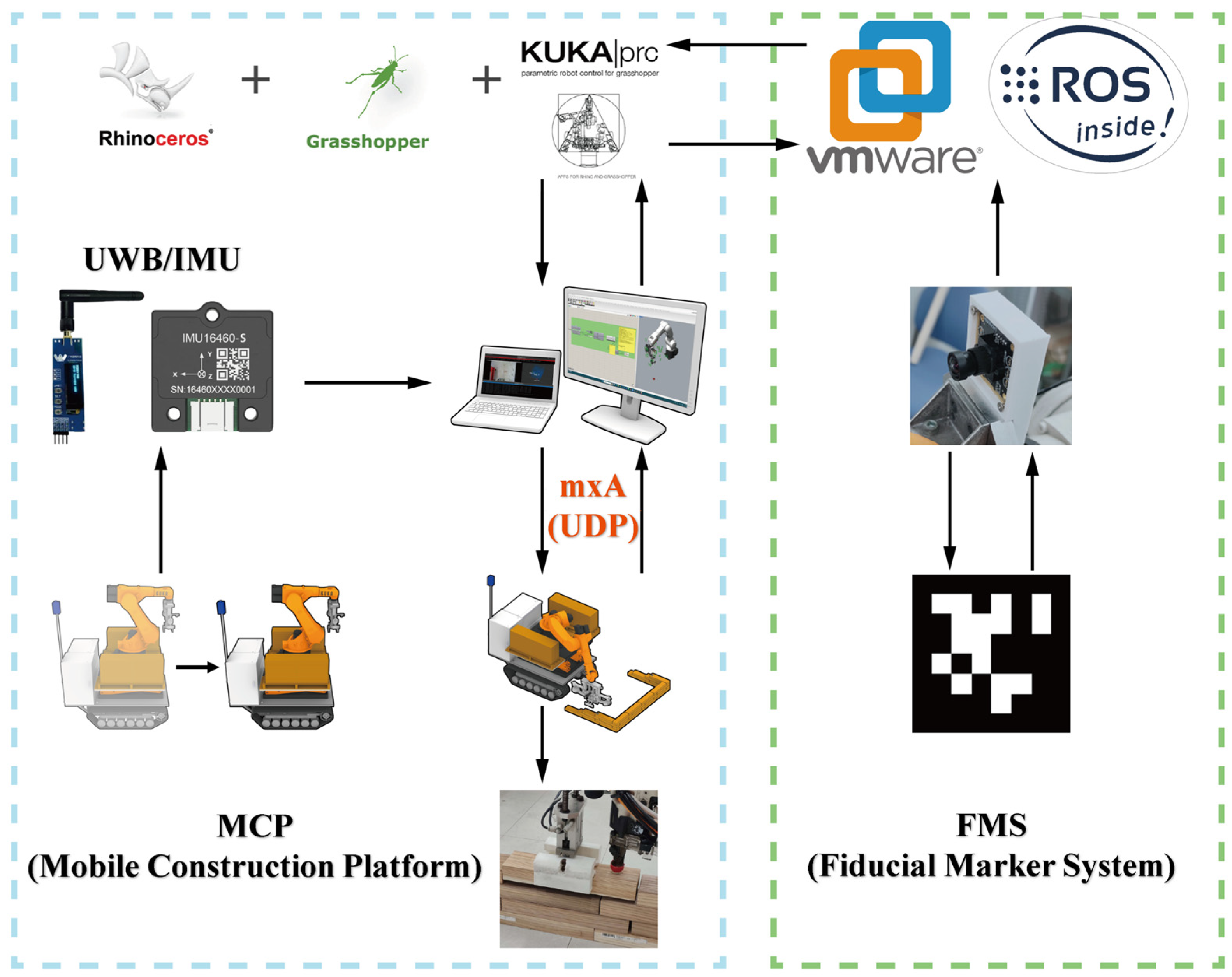
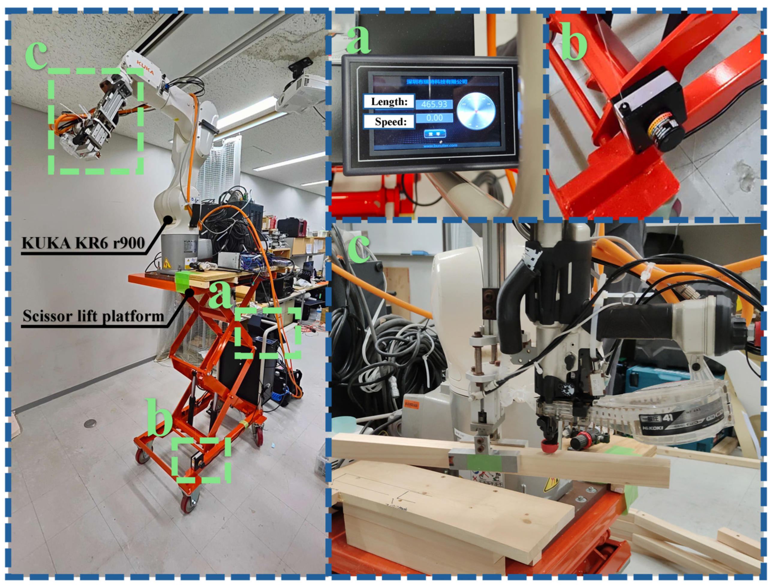
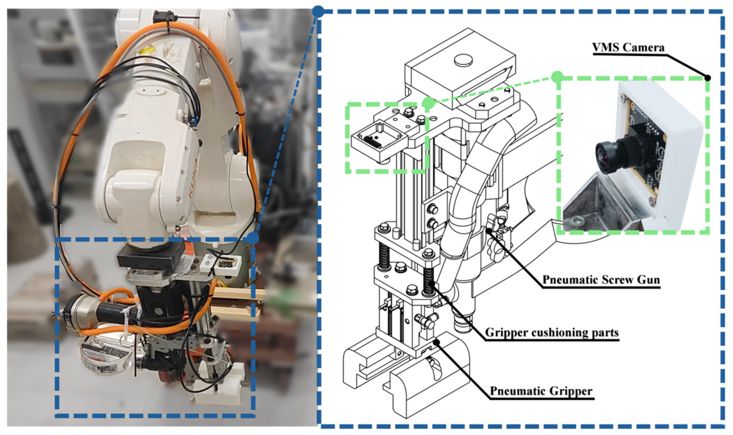
3.2. System Architecture Development

Based on the technological iterations and application scenarios described above, as illustrated in Figure 2, this paper proposes a construction system that integrates a lightweight visual positioning system (FMS architecture) with a mobile robotic platform. The design is centered on modularity and interchangeability, ensuring that the visual system can operate independently while efficiently collaborating with other components to meet the requirements of various environments, including indoor laboratories and construction sites.
The hardware of the system features a mobile platform equipped with a wheeled chassis and a scissor lift module to provide stable support for diverse operations. A KUKA industrial robot arm, paired with a KRC4 compact controller, is employed to achieve high-precision manipulation. The visual system is implemented via a USB fixed-focus camera module fitted with distortion-free or minimally distorted lenses (e.g., the HR4K800W with a 3.6 mm focal length and 90° field of view and the 5520_PCBA_5W with a 4.2 mm focal length and 75° field of view). These lenses offer multi-focal capabilities and adjustable parameters, making them compatible with a range of industrial robot arms from the KUKA KR6 series to the KR500 series.
To minimize interference and mechanical damage from vibrations during simulated timber construction, the camera module is mounted on the exterior of the robot arm’s end effector, positioned away from the gripper and nailing zones. Additionally, the system is outfitted with a custom multi-function end effector that integrates both gripping and nailing functions, a HIKOKI EC1445H3 mini air compressor, a notebook computer for operation and monitoring and a UWB/IMU fusion-based positioning system, all of which further enhance overall system stability and positioning accuracy.
Multi-sensor fusion offsets the limitations of any single positioning modality and therefore provides superior accuracy and stability. An inertial measurement unit (IMU), being immune to external disturbances, supplies self-contained dead reckoning that suppresses the stochastic errors inherent in ultra-wideband (UWB) ranging, while UWB measurements bind the long-term drift accumulated by the IMU. Leveraging this complementarity, the navigation subsystem employs an error-state Kalman filter (ESKF) to fuse UWB and IMU outputs, thereby enhancing overall positioning accuracy and robustness. Prior work demonstrates that, under dynamic motion, ESKF-based UWB/IMU fusion improves planar (XOY) positioning accuracy by 46% compared with UWB alone; when ported to a real KUKA KR60 MCP, the method achieves static positioning errors of 2.4 cm and 3.6 cm in the X and Y directions, respectively [55].
On the software and control side, the primary control environment is established on an Ubuntu virtual machine running under VMware Workstation, in conjunction with Windows 11 Professional. Collaborative control between the mobile platform and the robot arm is achieved through middleware, such as ROS (ROS1), KUKA KRL and EKI. The visual processing module employs AprilTag in combination with OpenCV and the image_transport library for target detection and positioning, while camera parameter calibration is fine-tuned using MATLAB-R2024a tools. The user interface and data processing platform are developed using Rhino 8 and Grasshopper, with the KUKA PRC plugin and mxAutomation module constructing an intuitive interface. Real-time data exchange between the visual detection module and the robot arm control unit is facilitated by LAN and VMware HGFS technologies, thereby ensuring robust self-feedback and real-time control capabilities.
The organic integration of these modules not only enhances component interchangeability and overall system robustness but also fully demonstrates the practical value and application potential of this mobile construction system in automated construction tasks.

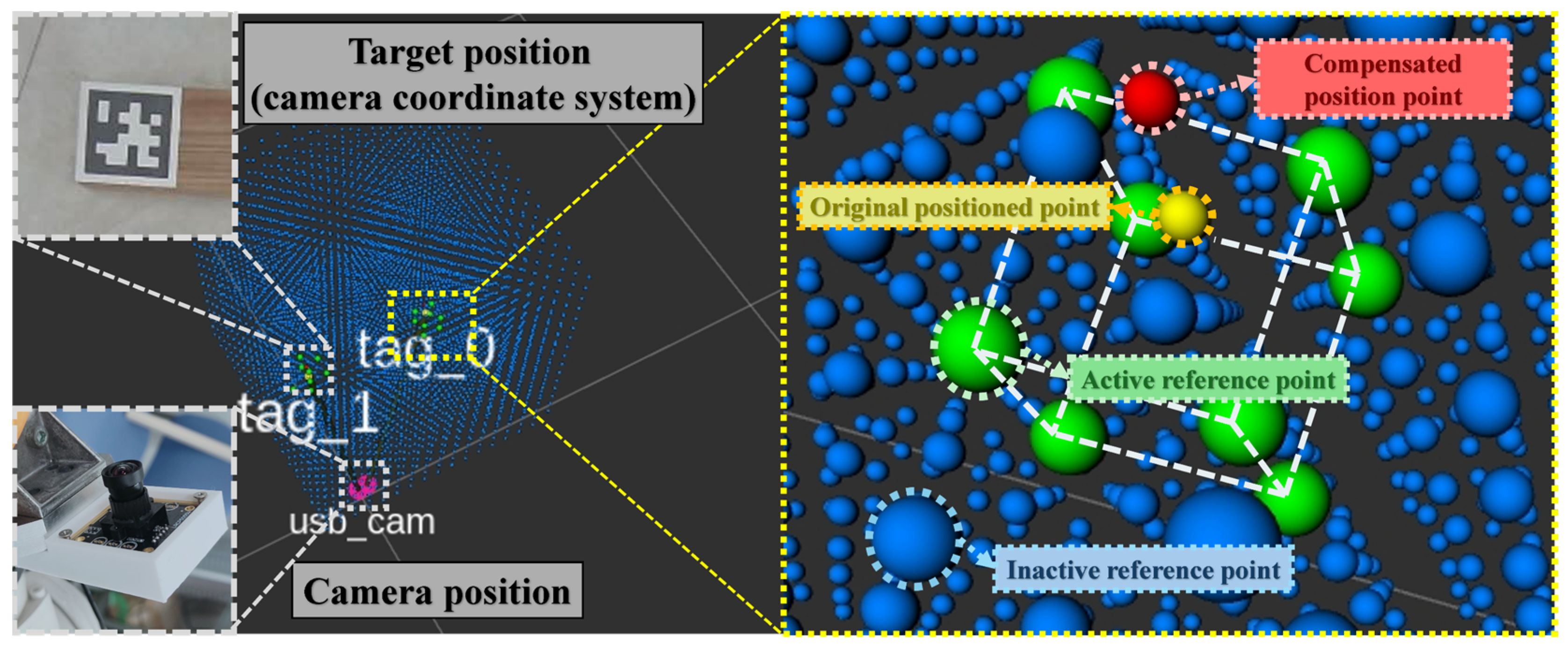
3.3. Design of the Self-Feedback Control System

The real-time communication and feedback control of the system primarily rely on VMware’s host–guest file system (HGFS) technology and KUKA’s mxAutomation robotic arm system extension (see Figure 3). The real-time pose information of the QR code tags is recorded in a shared folder on the virtual machine. Through VMware’s HGFS, these data are automatically synchronized to the host computer, where Python3 scripts in the Grasshopper environment read and parse the information. Subsequently, Grasshopper performs a coordinate transformation on the camera coordinates based on the current pose of the robotic arm—periodically provided by the KUKA controller’s mxAutomation interface via joint angles or end-effector pose—to map the detection results to real-world positions within the robotic arm’s base coordinate system.
Based on these transformed target position commands, Grasshopper further sends motion commands via UDP to the mxAutomation service on the KUKA controller, driving the robotic arm to execute the appropriate path planning or posture adjustments. Simultaneously, the robotic arm’s real-time motion state is fed back to Grasshopper over the same communication channel, forming a rapid closed-loop control system. Since this entire process iterates continuously at the millisecond level, each movement of the robotic arm can be corrected in real time using the latest visual detection results, thus enabling online compensation for system errors such as lens distortion and calibration bias and improving both positioning and motion accuracy. The UDP protocol plays a critical role in this process due to its lightweight nature and low latency, making it well suited for rapid transmission in industrial applications that demand high-frequency real-time control.
During operation, a real-time compensation algorithm further refines the accuracy of the fiducial marker (FMS) subsystem. First, a set of “reference points” is acquired offline: the KUKA KR6 manipulator, whose repeatability is ±0.03 mm, carries the camera module to sample a QR code target at many known poses throughout the camera’s three-dimensional field of view. The resulting dense dataset forms an error lattice that captures systematic biases, such as lens distortion and residual calibration offsets.
At run time, each newly measured pose is corrected by spatial interpolation. The algorithm queries the reference database for the nearest neighbors of the incoming point and computes an inverse distance weighted average of their stored errors. This yields an estimate of the local systematic bias, which is then subtracted from the raw measurement. The neighborhood interpolation scheme thus exploits the spatial distribution of reference points to provide local error estimates wherever the target remains within the calibrated workspace of the camera (see Figure 4).
The corrected poses are visualized in RViz and logged to external files. This procedure markedly mitigates distortion- and calibration-induced deviations, thereby enhancing the overall precision and robustness of the positioning system.

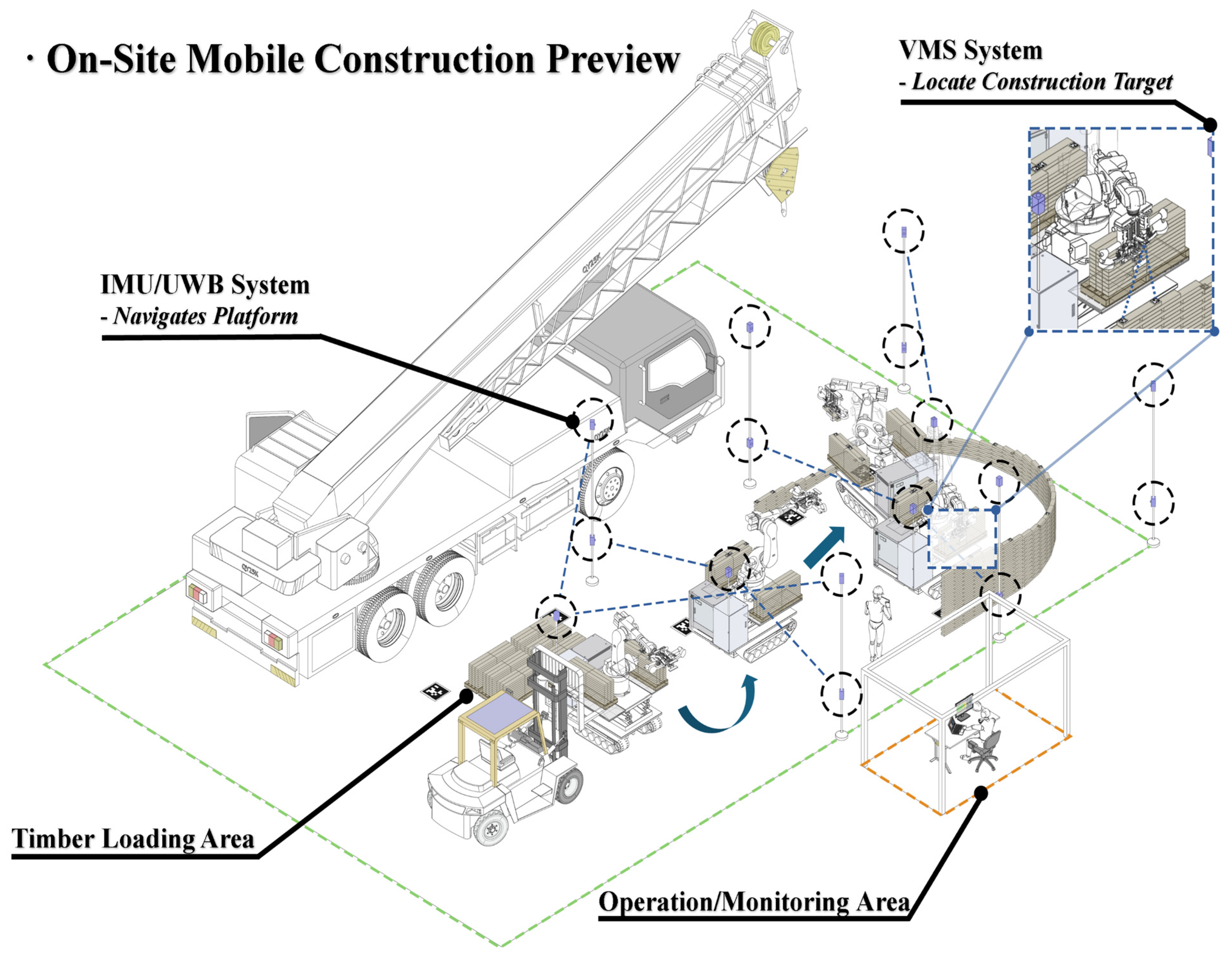
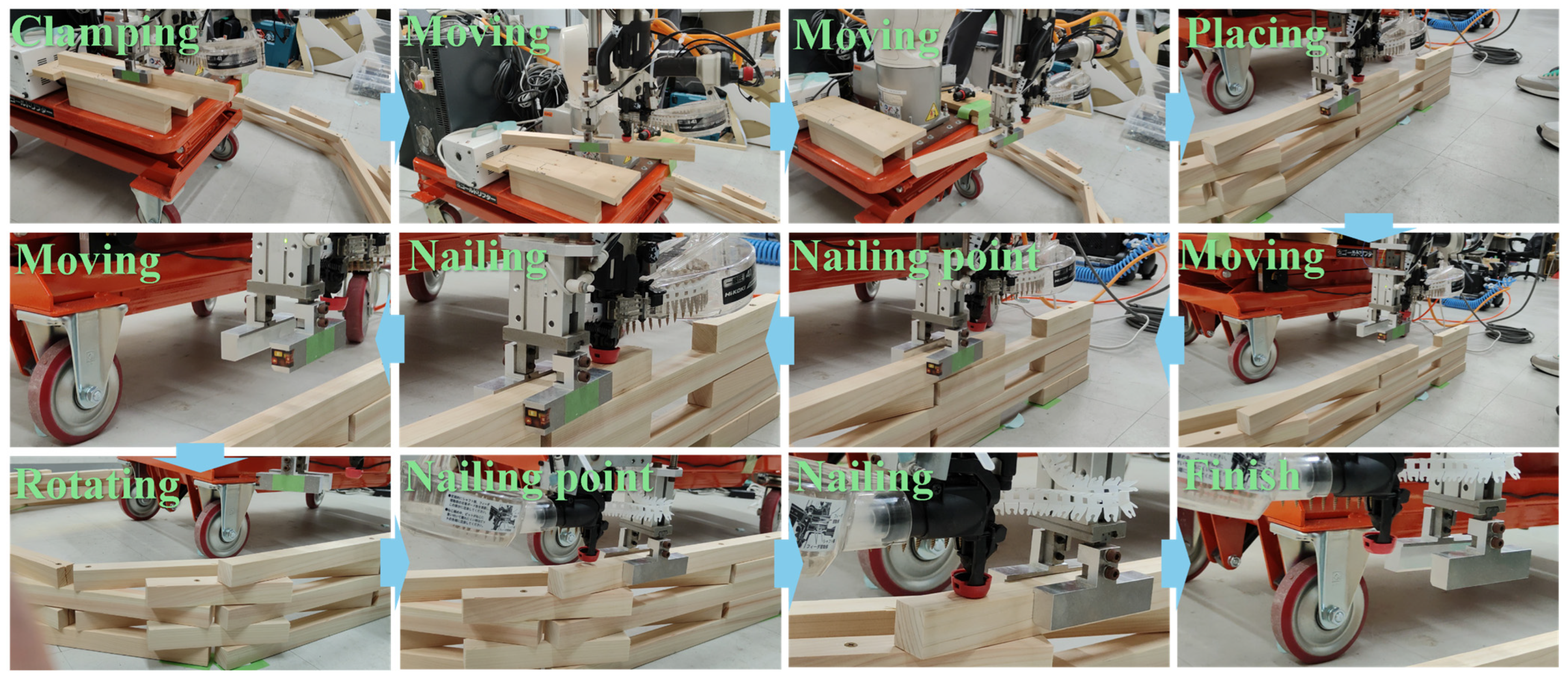
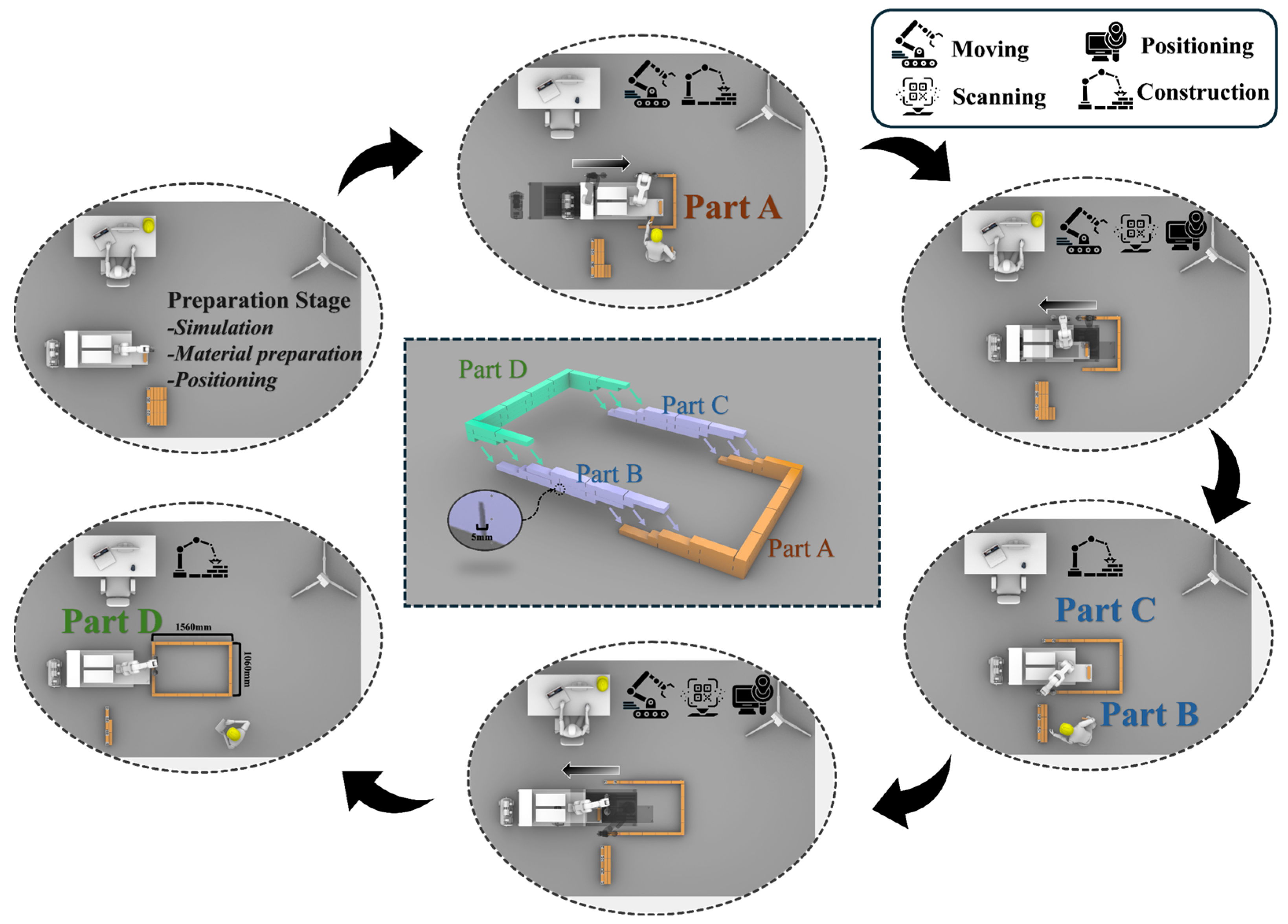
3.4. On-Site Construction Workflow Design and Performance Validation

Figure 5 presents the envisaged on-site timber construction scenario.
Once the mobile robotic construction platform is transported to the construction site, it initially achieves centimeter-level autonomous navigation using an all-terrain tracked base combined with an IMU/UWB navigation positioning system. This enables the platform to accurately move to the material stacking area for subsequent loading operations. On the platform, the robotic arm’s end effector is equipped with a visual positioning system based on the AprilTag algorithm that continuously detects QR code markers in the stacking area. The detected spatial coordinate information is transmitted to the PC client via KUKA mxAutomation, allowing construction personnel to precisely control and dynamically monitor the robotic arm using the KUKA PRC plugin within the Rhino/Grasshopper environment. After loading is complete, the platform moves—under the guidance of the navigation system—to the designated assembly area, where the end effector’s visual system is reactivated to perform high-precision positioning and error correction at the assembly starting point, thereby controlling navigation deviations within a millimeter range. During positioning, AprilTag markers are typically placed at both ends directly above the initial timber strip to ensure that their centers align with the pre-set timber placement, so that the robotic arm can accurately position the timber at the designated installation coordinates. Since building components are usually composed of multiple layers of timber strips, the system recalibrates the coordinate system every few layers to minimize cumulative errors. Once assembly reaches the second layer, the integrated pneumatic gripper and screw gun enable simultaneous grasping and nailing operations, further enhancing construction efficiency. For components exceeding the robotic arm’s working radius, the platform employs repeat movements and re-localizations—after completing each sub-procedure, it automatically moves to the next construction area and uses the QR code on the last timber piece to calibrate a new starting point—ensuring precise and seamless assembly across different sections.
To validate the feasibility and robustness of this workflow, the authors utilized the indoor experimental platform described in Section 4.3, enhanced with a dedicated visual positioning system, to comprehensively evaluate end-effector accuracy, system robustness and overall workflow reliability. The experiments primarily included spatial random point error analysis and system interference tests, wherein factors such as camera shooting angle, marker surface cleanliness and ambient lighting conditions were introduced as variables to further investigate their impact on target detection accuracy. For testing of the IMU/UWB navigation positioning system, please refer to [55].

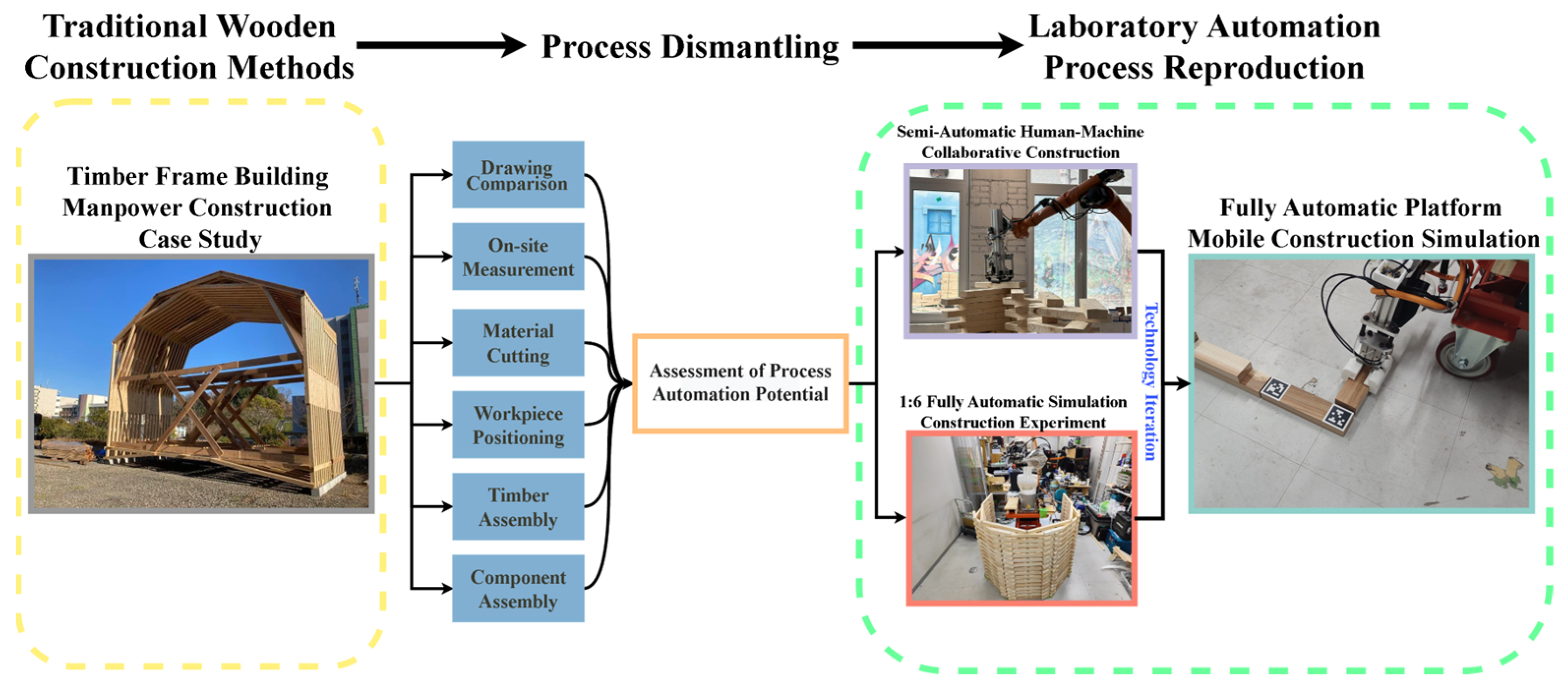
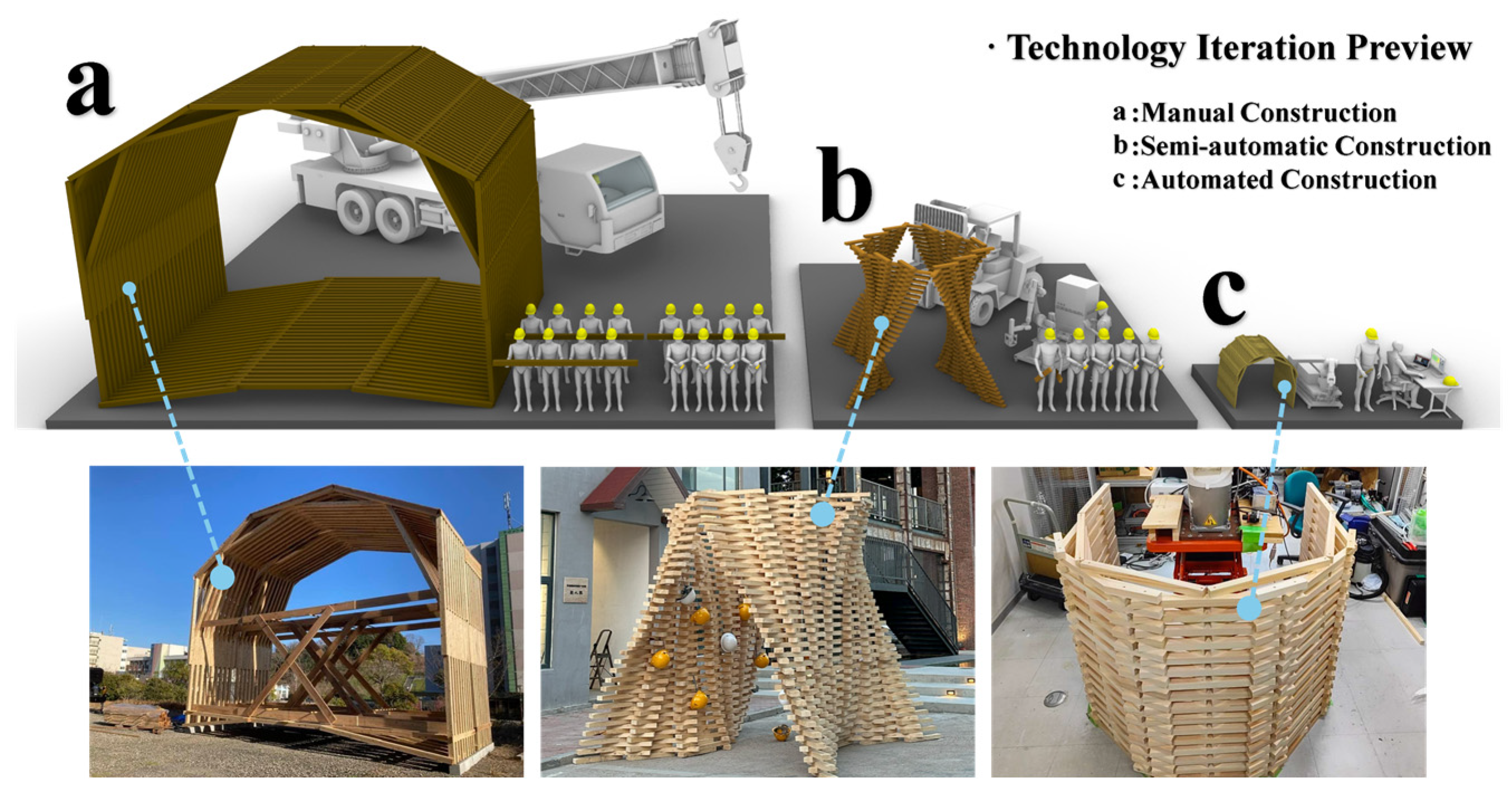
4. Construction Technology Dismantling and Iteration Review

This chapter begins with the traditional manual processes of timber construction, using the manpower construction process of a timber house as an example. It deconstructs each procedure and analyzes the potential for automation at every stage. Subsequently, the process is gradually reproduced in the laboratory, and the technological iteration during the laboratory phase is reviewed.

4.1. Deconstruction of the Timber Construction Technology

This section primarily presents the manual construction process of a timber house. The project is a teaching initiative, executed manually by more than ten students assembling the timber structure. The building is 6.5 m tall, 8.3 m wide and 6.7 m deep, and it is entirely constructed using 105 mm × 105 mm × 3000 mm timber.
The structural design of the building follows a modular stacked timber construction approach, employing timber components of consistent dimensions that are prefabricated and then stacked layer by layer. The overall structure is achieved through repetitive modular units (with a repeat configuration every two layers), a design strategy that considers construction efficiency and structural consistency from the outset. Therefore, during construction, workers do not need to repeatedly consult blueprints; they simply replicate the same structure multiple times to complete the building.
In actual construction scenarios, as shown in Figure 6, the building is assembled using a method that combines prefabricated assembly with lifting installation. Specifically, building components are first prefabricated and initially assembled on the ground. Lifting equipment is then used to raise the prefabricated modules or components to predetermined positions on site, where final on-site assembly and connections are completed.
As depicted in Figure 7, considering both worker safety and the challenges of lifting individual components, the entire building is divided into four identical sections for prefabricated assembly. The structure of this building is essentially determined by the specifications of the timber; the timber components interlock to form a stable construction. Due to the repetitive nature of the building’s layers, there is no need for repeat measurement or calibration of the site or timber during construction. Instead, the timber is positioned on the first two layers according to the blueprints, and this setup is then replicated throughout the remaining layers. For connecting the components, the project utilizes 150 mm wood screws, which are manually driven by workers using power drills.

4.2. Exploration of Semi-Automated Timber Construction

In this project, the authors conducted a workshop to explore a semi-automated construction process for timber construction and, through human–machine collaboration, built a medium-scale landscape timber structure covering 12.8 m2.
The building features two symmetrical hyperbolic surfaces, with the curvature of these surfaces expressed by timbers installed at various angles. From an architectural standpoint, constructing such complex curved forms demands an assembly precision that far exceeds what manual construction can achieve. Because the placement angle of every timber component must strictly conform to the predetermined curvature of the hyperbolic surfaces, conventional alignment or measurement methods prove either ineffective or inefficient, making it difficult to reach the required precision. Although relying on experienced craftsmen and extensive on-site calibration measures may partially achieve the desired outcome, manual construction overall is prone to cumulative errors, inefficient processes and high risks. In this context, the adoption of automated or semi-automated construction technologies becomes an inevitable choice to ensure structural stability and construction accuracy (see Figure 8).
Accordingly, in this project, the authors employed a KUKA kr20, equipped with a standard timber suction cup tool, as the construction device. The entire building was divided into 12 components, which were assembled separately and then hoisted together. In this process, the positioning and placement of timber blocks were executed entirely by the robotic arm according to a pre-programmed component assembly procedure developed by the designer, thereby completely eliminating the complex blueprint-based positioning steps and human placement errors. The connections between timber blocks were made by pausing the robotic arm’s movement once a block was positioned at the target location, allowing on-site personnel to secure it using a power drill and wood screws. The final assembly phase was then carried out at the designated building installation site with the assistance of forklifts, scaffolding and manual labor (see Figure 9).

4.3. Simulation of the Automated Timber Construction Process

Based on the previous experience with process deconstruction and semi-automated construction, in this project, the authors attempted a small-scale simulated construction experiment using an indoor laboratory robotic arm platform.
With the exception of timber supply, the entire construction process was carried out by a KR6 robotic arm and its associated automated equipment, successfully building a 1:6 scale experimental model of the building from the case in Section 4.1 within its working radius. For the purpose of fully automated construction, as shown in Figure 10, the design of the experimental platform incorporated a scissor lift platform along with an integrated pneumatic gripper–nailing end effector. The lift platform significantly extended the KR6 robotic arm’s workspace in the z-axis. To obtain real-time height variation data, a linear encoder position sensor was installed on the platform, synchronizing the lift data with the PC in real time, thereby allowing for appropriate adjustments to the construction program. The integrated end effector enables fully automated timber positioning, placement and connection.
As illustrated in Figure 11, during the construction process, the pneumatic gripper picks up a timber piece and places it at the target location. The gripper then secures the timber, and the robotic arm simulates a manual downward pressing motion to complete the nailing process. The gripper is equipped with a buffering mechanism, which, in combination with the robotic arm’s force feedback system, effectively prevents collisions during operation. In cases where excessive force is detected, the system automatically triggers an emergency stop to protect both on-site personnel and equipment. The nailing function is primarily executed by a HIKOKI pneumatic screw gun, which, operating at 0.95 MPa, uses an internal pneumatic screw mechanism to drive a Phillips head for rapid rotation and downward pressure. This facilitates quick fastening between timber (30 mm × 30 mm) and screws (41 mm in length, 3.9 mm in diameter). Additionally, the device’s chain-feed automatic screw loading mechanism supports multiple nailing operations.

4.4. Technology Iteration Analysis

Based on the analysis of the traditional manual construction process for modular stacked timber buildings, automated tools have demonstrated significant potential in key stages, including prefabricated assembly, lifting installation and component connection. In the prefabrication phase, integrating robotic arms with high-precision visual and sensor technologies enables automatic positioning, precise assembly and real-time quality monitoring. During the lifting stage, hoisting equipment equipped with integrated positioning sensors and visual systems ensures accurate alignment and dynamic adjustment of prefabricated modules during lifting and docking. In the component connection phase, automated nailing devices not only replace manual operations to enhance efficiency but also leverage force sensor feedback from the robotic arm to ensure connection accuracy and structural stability. Moreover, the limited working radius of conventional six-axis robotic arms poses challenges; while industrial practices often employ high-precision servo rails to extend the working space, the transportation, installation and subsequent removal of such large rails are impractical in on-site construction environments. Consequently, a mobile robotic construction platform with an integrated high-precision positioning system emerges as a feasible solution for on-site applications.
Practical semi-automated construction experiments reveal that although automation offers substantial advantages for handling complex architectural forms, issues such as safety, human resource coordination and assembly precision remain. For instance, human–robot collaboration demands high team coordination and operator expertise; prolonged operations may increase safety risks; and excessive segmentation of components can lead to cumulative errors during final assembly. Under the improved experimental process and platform, researchers achieved continuous assembly of a 1:6 scale model through four successive lifts along the z-axis, reducing personnel requirements to just two (a robotic arm operator and a timber supply operator) and significantly enhancing efficiency and smoothness (see Figure 12).
These phased advances inform future on-site process development. The current challenges focus on platform mobility and positioning system development; with mature industrial mobile platforms available, subsequent research will target high-precision positioning systems and closed-loop self-feedback control among subsystems. Although Section 3 proposes a staged solution, extensive testing is required to confirm the system’s robustness and workflow reliability before fully transitioning the technology from the laboratory to real-world construction scenarios.

5. Construction Workflow Design and Experimental Analysis

Based on the deconstruction of traditional timber construction processes and previous technological iterations, this chapter primarily validates the precision and robustness of the core visual positioning system within the workflow proposed in Section 3.4. Finally, using a small-scale experimental platform, the entire process is comprehensively validated in an indoor environment. By employing timber bricks measuring 245 mm × 60 mm × 30 mm for simulated timber assembly tests, both random timber block positioning experiments and simplified small-scale timber construction tests were conducted, further verifying the reliability of the automated on-site construction solution based on the visual positioning system in actual timber construction. As shown in Figure 13, based on the previous experimental platform, the authors integrated the VMS camera into the end effector. This lightweight platform simulates a realistic timber construction scenario in an indoor laboratory environment, providing a reliable and controllable testbed for evaluating system performance, robustness and accuracy.

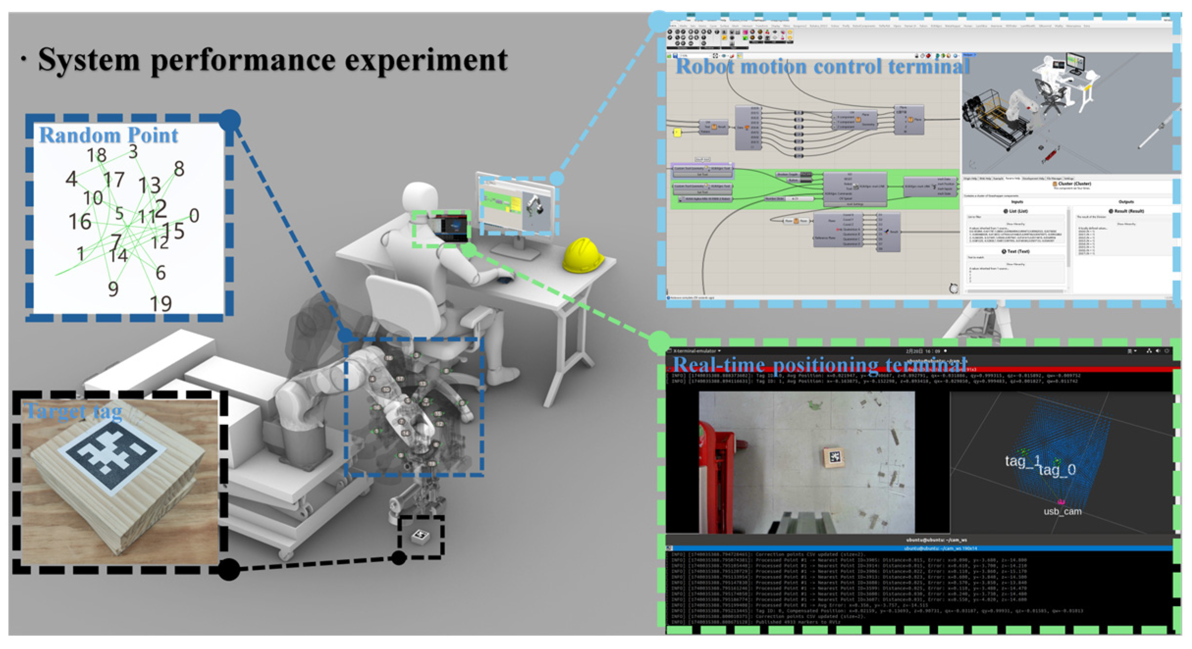
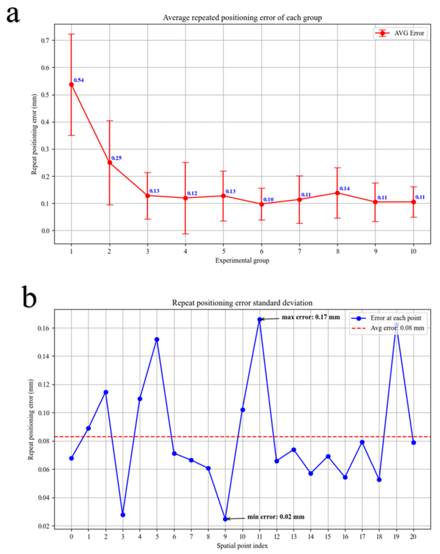
5.1. Performance Verification of the Visual Positioning System

To quantitatively evaluate the performance of the visual positioning system (FMS) proposed in this paper, the authors used Grasshopper to generate 21 random points within the spatial domain covered by the error model as experimental targets. This approach reduces human bias and more comprehensively covers the entire detection area, thereby improving the statistical representativeness and objectivity of the data. During operation, the image processing module was executed on a workstation equipped with an AMD Ryzen 9 5900HX CPU; each frame had a resolution of 2048 × 1536 pixels and was processed at 30 fps.
As shown in Figure 14, based on the known accurate coordinates of the tags to be measured, the robotic arm executed a motion trajectory through these 21 points and paused for 10 s at each sampling point as the detection time. During this process, imaging posture and ambient lighting conditions were essentially maintained constant, and detection data were monitored and saved via ROS nodes. This procedure yielded 21 × 10 sets of three-dimensional coordinate data. For each test point, the i th measurement is denoted as x i y i z i (in meters). These data were then organized and stored in a CSV file with headers, forming the raw input for subsequent analysis.
Considering the presence of noise and occasional large errors, this research first performed outlier removal on the 10 measurements for each test point. For all measurements x i y i z i i = 1 10 of a test point, this research computed the mean in three-dimensional space as
p ¯ = ( x , y , z ) = 1 10 i = 1 10 ( x i , y i , z i )  
Next, the Euclidean distance of each measurement from this mean p ¯ was defined as
d i = ( x i , y i , z i ) p 2
The average error d ¯ and standard deviation   σ d of these distances were then computed. If any measurement’s distance   d i exceeded the threshold, it was considered an outlier and excluded from further calculations.
d ¯ + k σ d
Here, k is an empirical parameter; based on the measurement environment and preliminary experimental results, this paper set k = 2.
After excluding outliers, the remaining measurements for each point were averaged again to obtain the final “average position” for that point. The Euclidean distance between the i th valid measurement and the average position is considered the error for that measurement:
e i = p i p ¯ 2
where P i = ( x i , y i , z i ) denotes the valid measurement. To quantify the “repeatability” of the system at that point, the standard deviation of all measurement errors was calculated as
σ p o i n t = 1 N i = 1 N   e i e ¯ 2
where e ¯ is the mean of all valid measurement errors, and N is the number of measurements remaining after outlier removal. This standard deviation reflects the dispersion of repeat measurements at the same spatial point and is one of the key indicators used in this study to evaluate repeatable positioning accuracy.
The detailed analysis results are shown in Figure 15. Figure 15a and Figure 15b, respectively, present the average repeat positioning error for each experimental group and the standard deviation of the repeat positioning errors for each spatial sampling point.
In Figure 15a, it can be observed that the first group (group 1) exhibited a relatively large average error of approximately 0.54 mm, with a high standard deviation, indicating that the measurement errors across all spatial points in this group were relatively dispersed. In subsequent groups, the average error noticeably decreased and stabilized; for instance, group 3’s average error dropped to 0.17 mm, and the remaining groups generally showed errors in the range of 0.1–0.2 mm, demonstrating improved performance and higher stability. This suggests that the measurements in the initial group (group 1) were less stable, likely due to environmental factors or equipment initialization. However, from an overall perspective (see Figure 15b), the system’s average repeatability can reach 0.08 mm, with the highest standard deviation among all spatial points being approximately 0.17 mm and the lowest around 0.02 mm. The average error and standard deviation across multiple measurement rounds are within the same order of magnitude, with no evidence of significant systematic drift. This indicates that the experimental setup and imaging environment maintained good overall consistency.
Nonetheless, in some rounds, there was a slight increase in measurement errors across all points, which is speculated to be related to external disturbances during testing (e.g., slight camera shake, anomalous AprilTag detection frames) as well as network/hardware synchronization delays. Overall, in an indoor environment free from major disturbances, the system demonstrates excellent repeatable positioning accuracy.
Based on these tests, the measured coordinate data were compared with the actual tag position coordinates derived from the robotic arm path in Grasshopper, yielding the directional errors and distance error (EX, EY, EZ, ED). Subsequently, the statistical metrics for these four types of errors were calculated to evaluate the system’s positioning accuracy. The error variables used in the experiment are defined as follows.
E X , E Y , E Z represent the measurement deviations in the x, y and z directions (in mm), respectively.
E D represents the spatial distance error (e.g., Euclidean distance deviation), also referred to as the “distance error”.
For the measurement results of the system, descriptive statistical indicators, such as the mean error, standard deviation and root mean square error (RMSE), were calculated as follows:
  M e a n   = 1 N i = 1 N e i
S t d   = 1 N 1 i = 1 N   e i e 2
R M S E   = 1 N i = 1 N   ( e i ) 2
where e i denotes the error of the i th measurement, and N represents the total number of measurements for that error type (in this study, N is the total number of points and repeat tests collected for each error type).
Table 2 shows the mean, standard deviation and RMSE for each error type measured during the tests.
Based on the above data, the visual positioning system demonstrates good positioning accuracy along all axes, with an RMSE of only 1.08 mm in the distance direction and a standard deviation of 0.38 mm. Overall, the system exhibits high precision and stability in all directions; although the z-axis shows slightly higher errors, the overall error is controlled at around 1 mm, which meets millimeter-level positioning requirements. For on-site mobile construction, such precision is fully acceptable, particularly in scenarios demanding high-precision assembly and precise positioning. Under normal conditions, the system maintains excellent stability and robustness. However, practical applications must also account for uncertainties brought by the on-site environment, which may necessitate further system calibration and environmental adaptation optimizations to ensure that this high level of precision is maintained even in dynamic and complex construction settings.

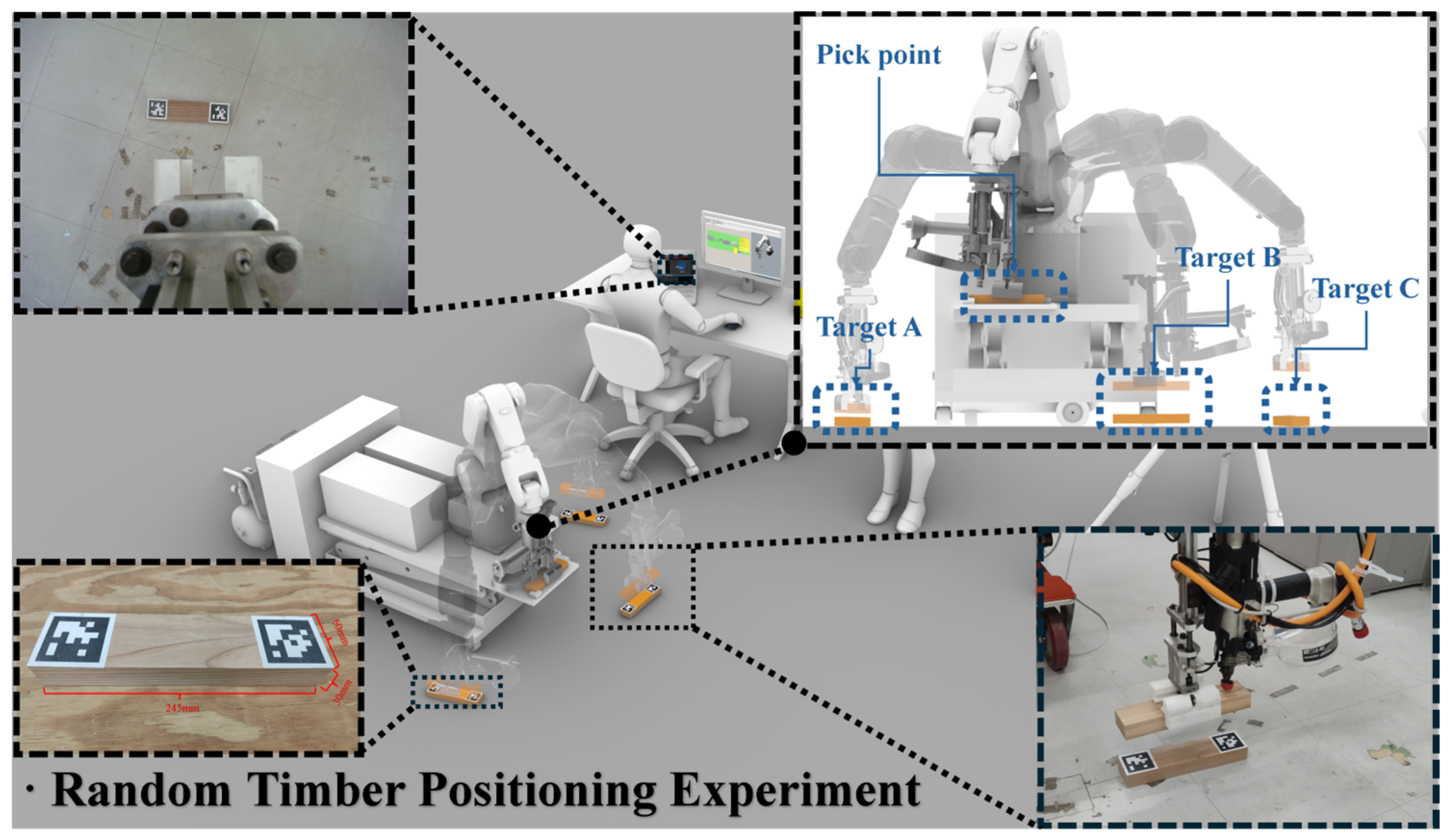
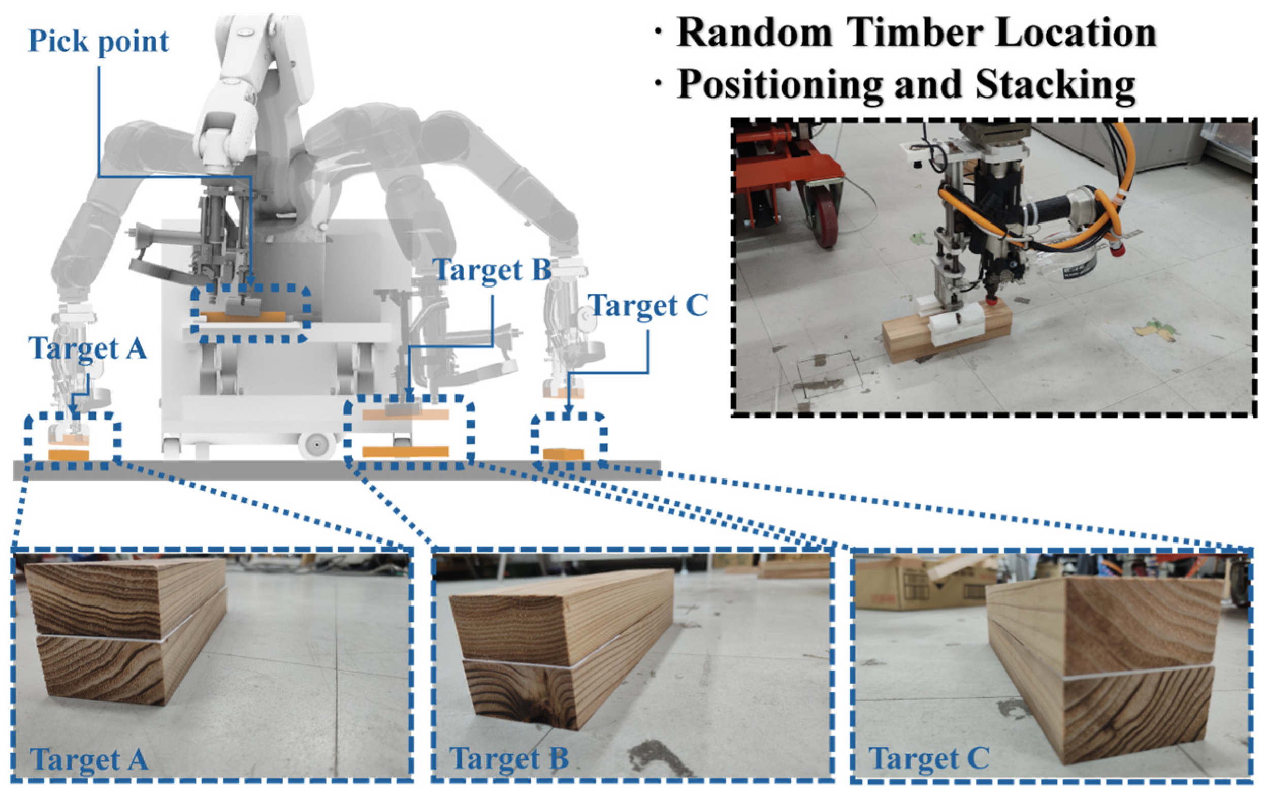
5.2. Random Timber Position Stacking Experiment

In the experiments described in this section and in Section 5.4, the authors employed an experimental platform to conduct simple, small-scale indoor simulations of potential application scenarios in the envisaged on-site timber construction. The primary goal of these experiments was to evaluate whether the positioning system and the robotic system could effectively coordinate and control operations in a real construction environment and reliably complete the predetermined task objectives using the prescribed methodology.
In this set of experiments, three timber blocks with QR code labels were placed at random positions within the working radius of the robotic arm. First, the robotic arm positioned the camera above each target for 10 s to obtain accurate pose data. Then, by executing the workflow described in Section 3.4, the precise poses of the three target timber blocks were obtained in Grasshopper. Subsequently, using mxAutomation, real-time commands were issued to the robotic arm to execute the grasping and placement operations, orderly stacking the timber blocks from the pre-set grasping points onto the target positions, as illustrated in Figure 16. The degree of overlap between the placed timber and the target timber was then observed to assess the system’s reliability in completing this task.
During the experiment, the system demonstrated excellent accuracy and stability. As shown in Figure 17, multiple trials revealed that the system performed outstandingly in target positioning and in navigating the robotic arm, effectively achieving the pre-set objectives of positioning → grasping → stacking.
Across several trials, the misalignment between timber blocks was generally less than 2 mm. Considering the errors introduced by timber processing tolerances and external factors, such as robotic arm vibration, these results confirm that the FMS system presented in this paper significantly enhances the end-effector precision of the timber construction system. Therefore, given that the positioning system itself meets the required accuracy, further improvements in overall system precision—via process enhancements (e.g., improvements in timber preparation and gripper calibration) or adjustments to the robotic arm’s motion program—will be necessary in subsequent research.

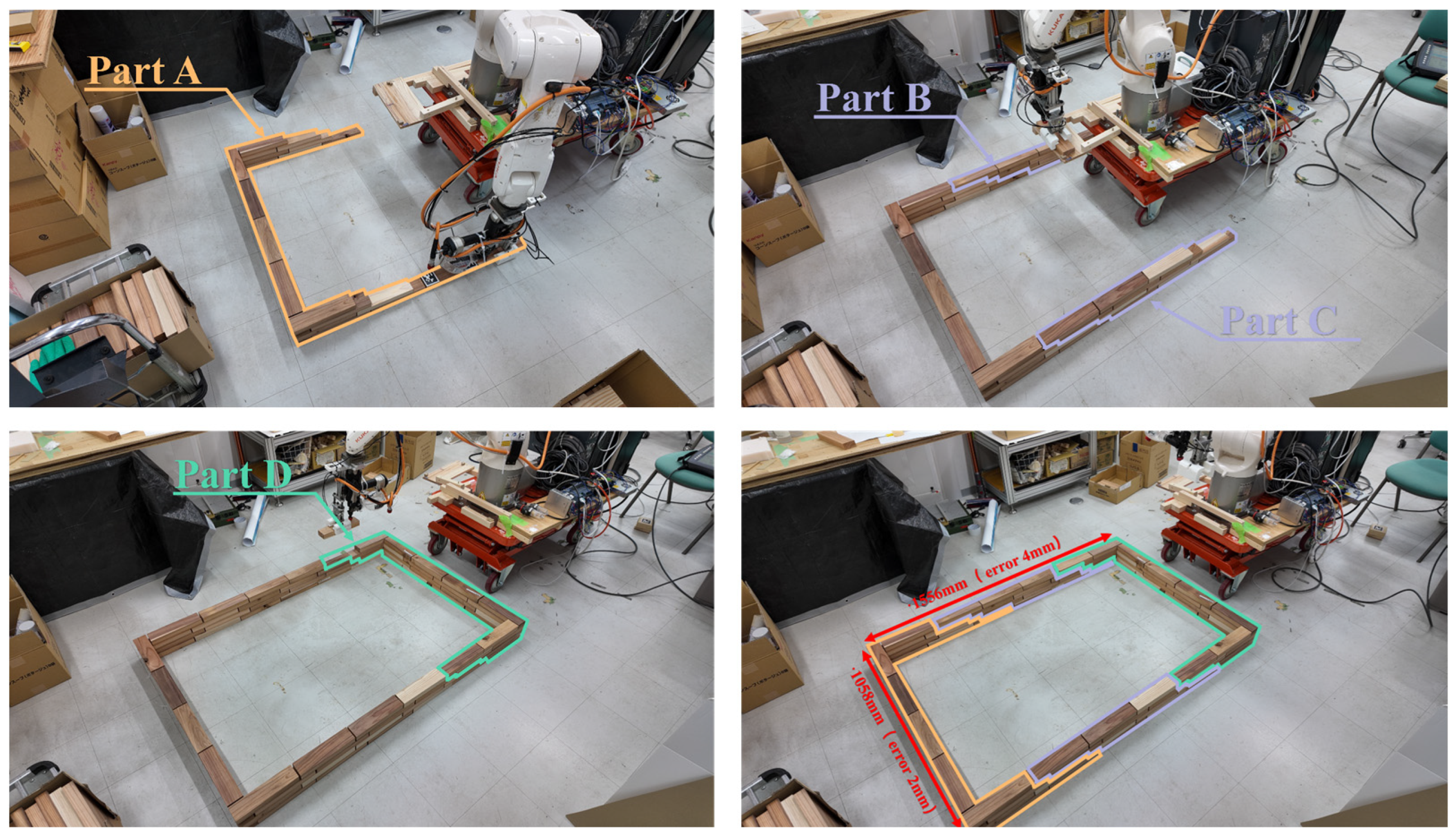
5.3. Simplified Timber Structure Assembly Experiment

Building on the previous experiments, this study further designed a simplified, small-scale mobile timber assembly experiment in an indoor setting based on the experimental platform. The objective was to demonstrate the feasibility of the proposed method and workflow for full-scale on-site timber construction scenarios described in Section 5.1.
In this experiment, a small four-layer masonry timber component was designed as the test object, with overall dimensions of 1560 mm (length), 1060 mm (width) and 120 mm (height), using timber bricks measuring 245 mm × 60 mm × 30 mm. Although these dimensions are relatively small for building components, they exceed the working radius of the KUKA KR6 R900 robotic arm used on the experimental platform, thereby necessitating multiple movements to complete the assembly. Consequently, the entire simulation closely follows the actual workflow of on-site timber construction and can serve as a process reference for future construction using larger equipment.
Due to the requirement to complete the assembly through multiple movements, it was necessary to pre-split the target component into sections. The splitting logic was to minimize the number of platform movements while ensuring that the assembly of each section was not compromised, thereby enhancing overall efficiency. As a result, the model was divided into four parts, requiring three platform movements for assembly, with a 5 mm gap between each timber brick to accommodate the errors caused by vibrations of the robotic arm and the mobile platform.
The specific workflow is illustrated in Figure 18. Each step was executed strictly according to the pre-set procedure described in Section 3.4. However, since this experiment was a simplified small-scale test aimed at verifying the workflow and system reliability, the nailing step was omitted (for details on the nailing process, see Section 4.3).
During the experiment, as shown in Figure 19, the system effectively assisted the experimental platform in completing the predetermined assembly task. A total of 80 timber bricks were assembled in 1 h and 46 min, including two instances of repositioning and re-localization. The overall process demonstrated smooth operation and precision that met the design expectations. The assembled experimental model measured 1556 mm in length and 1058 mm in width; compared to the pre-set dimensions (1560 mm and 1060 mm), the cumulative dimensional errors were 4 mm and 2 mm, respectively, which are well within the anticipated range. In summary, the authors successfully reproduced the workflow described in Section 5.1 using the experimental platform, achieving fully automated mobile timber assembly in a laboratory environment and further advancing the process iteration.

5.4. Results and Discussion

The experimental results demonstrate that the proposed autonomous construction system achieves high accuracy and reliability across all test scenarios. During the positioning and assembly tests, the system maintained millimeter-level positioning accuracy, with translational errors of approximately 1 mm and an average repeat positioning accuracy of up to 0.08 mm, which underscores the effectiveness of the calibration and sensing processes. Based on this high-precision positioning, the robotic system is capable of accurately identifying target locations under various conditions and assembling structural components with minimal deviation, achieving precision that surpasses traditional manual construction tolerances, with excellent repeatability and consistent error distribution. Compared with existing visual positioning systems in the construction industry, the FMS positioning system used in this study demonstrated an average accuracy of 1.08 mm with a standard deviation of 0.38 mm. This represents a significant improvement over the 3.33 mm (std 6.07 mm) reported by Shengtao Tan et al. [54] and the average positioning accuracy of 15.8 mm/0.45° reported by the ETH “In situ Fabricator” project [33].
Notably, conventional offline programming for on-site construction typically relies on pre-measured planar data; however, since actual construction sites are generally near-planar with localized irregularities, such methods fail to accurately reflect the true conditions. Moreover, mxAutomation rejects pre-measured planar data. Therefore, this system not only enables real-time positioning to guide robotic arm operations but also establishes an alignment mechanism between the marker coordinates and construction measurement benchmarks through on-site QR code calculations, thereby meeting the practical demands for high positioning accuracy in on-site construction. In summary, this experimental study validates the overall workflow, demonstrating the technical reliability of the proposed method through comprehensive tests of the positioning system’s accuracy, robustness and the complete construction process.

6. Conclusions

The mobile robotic construction platform guided by a visual positioning system is of significant importance for advancing the automation of traditional on-site timber construction processes. This study deconstructed the process of modular stacked timber construction through a detailed case analysis and progressively reproduced these processes in the laboratory using automated methods. Based on long-term process exploration, system development and iterative technological improvements, a feasible workflow for on-site timber construction—integrating a real-time visual positioning system with a mobile robotic platform—was proposed. The reliability, robustness and end-effector precision of this method and system were validated through precision testing experiments and physical assembly trials, thereby achieving the deconstruction and automated regeneration of traditional timber construction processes.
Thus, the main contributions of this study are as follows.
The developed system demonstrates extremely high positioning accuracy and end-effector precision. The experimental results indicate that this vision-based positioning method can reliably maintain accuracy at the millimeter or even sub-millimeter level, thereby ensuring the success of subsequent construction tasks and validating the feasibility of applying the FMS system in on-site construction.
Utilizing a self-feedback system architecture, the proposed automated construction system is capable of real-time planning and correction of the robotic arm’s path based on the current positions of on-site components without human intervention, thereby exhibiting strong adaptability to unpredictable on-site environments.
However, while the proposed method and system showed promising performance in early laboratory validations, several outdoor, real-world tests are required before fully transitioning to full-scale on-site construction projects. Additionally, scaling this process from small laboratory equipment to a construction system based on large industrial robotic arms presents further challenges, such as coordinating delays among multiple systems and addressing the coverage limitations of the visual positioning system. Future work will focus on advancing this process from the laboratory to large-scale practical on-site construction projects, thus facilitating the transformation of traditional timber construction from artisanal methods to fully automated processes.

Author Contributions

Conceptualization, K.B., D.W. and X.S.; methodology, K.B.; software, K.B.; validation, K.B., C.S. and H.Z.; formal analysis, K.B.; investigation, X.S.; resources, H.F.; data curation, K.B.; writing—original draft preparation, K.B.; writing—review and editing, X.S., D.W. and P.D.; visualization, K.B. and W.Z.; supervision, H.F.; project administration, X.S.; funding acquisition, H.F. All authors have read and agreed to the published version of the manuscript.

Funding

This research was funded by the National Natural Science Foundation of China (No.52008224), the Tianjin Municipal Science and Technology Bureau (22YFZCSN00140), and (23ZGCXQY00010).

Data Availability Statement

The dataset is available on request from the authors. The raw data supporting the conclusions of this article will be made available by the authors on request.

Acknowledgments

This research was conducted with the support of collaborative teamwork and international cooperation. We express our sincere gratitude to the Hiroatsu Fukuda Laboratory at the University of Kitakyushu for providing the venue and equipment support, and we are deeply indebted to collaborators from the University of Kitakyushu, Qingdao University of Technology and Tianjin Chengjian University for the invaluable technical guidance. Furthermore, we extend our special thanks to Yijun Jiang and Yanfu Li from the Fukuda Lab of the University of Kitakyushu, as well as Chaoran Wang from the Digital Architecture & Manufacture Laboratory at Qingdao University of Technology, for their insightful suggestions and unwavering assistance throughout the research process.

Conflicts of Interest

The authors declare no conflicts of interest.

Abbreviations

The following abbreviations are used in this manuscript:
AECArchitecture, Engineering and Construction
MCPMobile Construction Platform
FMSFiducial Marker System
UWBUltra-Wideband
IMUInertial Measurement Unit
UDPUser Datagram Protocol
HGFSHost–Guest File System
ATEAbsolute Trajectory Error
LOSLine-of-Sight
NLOSNon-Line-of-Sight
ESKFError-State Kalman Filter

References

  1. United Nations Environment Programme. 2020 Global Status Report for Buildings and Construction: Towards a Zero-Emission, Efficient and Resilient Buildings and Construction Sector; United Nations Environment Programme: Nairobi, Kenya, 2020. [Google Scholar]
  2. Chai, H.; So, C.; Yuan, P.F. Manufacturing Double-Curved Glulam with Robotic Band Saw Cutting Technique. Autom. Constr. 2021, 124, 103571. [Google Scholar] [CrossRef]
  3. Orlowski, K. Automated Manufacturing for Timber-Based Panelised Wall Systems. Autom. Constr. 2020, 109, 102988. [Google Scholar] [CrossRef]
  4. Krieg, O.D.; Lang, O. Adaptive Automation Strategies for Robotic Prefabrication of Parametrized Mass Timber Building Components. In Proceedings of the 2019 36th ISARC, Banff, AB, Canada, 21–24 May 2019. [Google Scholar]
  5. Wagner, H.J.; Alvarez, M.; Kyjanek, O.; Bhiri, Z.; Buck, M.; Menges, A. Flexible and Transportable Robotic Timber Construction Platform—TIM. Autom. Constr. 2020, 120, 103400. [Google Scholar] [CrossRef]
  6. Younis, A.; Dodoo, A. Cross-Laminated Timber for Building Construction: A Life-Cycle-Assessment Overview. J. Build. Eng. 2022, 52, 104482. [Google Scholar] [CrossRef]
  7. Hemmati, M.; Messadi, T.; Gu, H.; Seddelmeyer, J.; Hemmati, M. Comparison of Embodied Carbon Footprint of a Mass Timber Building Structure with a Steel Equivalent. Buildings 2024, 14, 1276. [Google Scholar] [CrossRef]
  8. ARUP-Embodied-Carbon-Timber. 07762000-RP-SUS-0002. 5 June 2023. Available online: https://www.istructe.org/IStructE/media/Public/Resources/ARUP-Embodied-carbon-timber_1.pdf (accessed on 25 March 2025).
  9. Drewniok, M.; Campbell, J.; Orr, J. SI for the Paper: The Lightest Beam Method—A Methodology to Find Ultimate Steel Savings and Reduce Embodied Carbon in Steel Framed Buildings. 2020. Available online: https://www.repository.cam.ac.uk/handle/1810/307047 (accessed on 25 March 2025).
  10. Kanagaraj, B.; Anand, N.; Samuvel Raj, R.; Lubloy, E. Techno-Socio-Economic Aspects of Portland Cement, Geopolymer, and Limestone Calcined Clay Cement (LC3) Composite Systems: A-State-of-Art-Review. Constr. Build. Mater. 2023, 398, 132484. [Google Scholar] [CrossRef]
  11. Wang, R.R.; Zhao, Y.Q.; Babich, A.; Senk, D.; Fan, X.Y. Hydrogen Direct Reduction (H-DR) in Steel Industry—An Overview of Challenges and Opportunities. J. Clean. Prod. 2021, 329, 129797. [Google Scholar] [CrossRef]
  12. Ramage, M.H.; Burridge, H.; Busse-Wicher, M.; Fereday, G.; Reynolds, T.; Shah, D.U.; Wu, G.; Yu, L.; Fleming, P.; Densley-Tingley, D.; et al. The Wood from the Trees: The Use of Timber in Construction. Renew. Sustain. Energy Rev. 2017, 68, 333–359. [Google Scholar] [CrossRef]
  13. Willmann, J.; Knauss, M.; Bonwetsch, T.; Apolinarska, A.A.; Gramazio, F.; Kohler, M. Robotic Timber Construction—Expanding Additive Fabrication to New Dimensions. Autom. Constr. 2016, 61, 16–23. [Google Scholar] [CrossRef]
  14. Möller, C.; Schmidt, H.C.; Koch, P.; Böhlmann, C.; Kothe, S.-M.; Wollnack, J.; Hintze, W. Machining of Large Scaled CFRP-Parts with Mobile CNC-Based Robotic System in Aerospace Industry. Procedia Manuf. 2017, 14, 17–29. [Google Scholar] [CrossRef]
  15. Parikh, P.; Kalamdane, S.; Rasal, A.; Mundada, K.; Kalshetti, U. SPArK-Bot: An Educational Robotic Platform. In Proceedings of the 2022 IEEE Global Engineering Education Conference (EDUCON), Tunis, Tunisia, 28–31 March 2022; pp. 1628–1633. [Google Scholar]
  16. Chu, B.; Jung, K.; Lim, M.-T.; Hong, D. Robot-Based Construction Automation: An Application to Steel Beam Assembly (Part I). Autom. Constr. 2013, 32, 46–61. [Google Scholar] [CrossRef]
  17. Melenbrink, N.; Werfel, J.; Menges, A. On-Site Autonomous Construction Robots: Towards Unsupervised Building. Autom. Constr. 2020, 119, 103312. [Google Scholar] [CrossRef]
  18. Bock, T.; Linner, T. Construction Robots: Elementary Technologies and Single-Task Construction Robots; Cambridge University Press: Cambridge, UK, 2016; ISBN 978-1-107-07599-3. [Google Scholar]
  19. Castro-Lacouture, D. Construction Automation. In Springer Handbook of Automation; Nof, S.Y., Ed.; Springer: Berlin/Heidelberg, Germany, 2009; pp. 1063–1078. ISBN 978-3-540-78831-7. [Google Scholar]
  20. Bock, T.; Linner, T. Site Automation: Automated/Robotic On-Site Factories, 1st ed.; Cambridge University Press: Cambridge, UK, 2015; ISBN 978-1-107-07597-9. [Google Scholar]
  21. Bechthold, M. The Return of the Future: A Second Go at Robotic Construction. Archit. Des. 2010, 80, 116–121. [Google Scholar] [CrossRef]
  22. Ardiny, H.; Witwicki, S.; Mondada, F. Are Autonomous Mobile Robots Able to Take Over Construction? A Review. Int. J. Robot. 2015, 4, 10–21. [Google Scholar]
  23. Helm, V.; Ercan, S.; Gramazio, F.; Kohler, M. Mobile Robotic Fabrication on Construction Sites: DimRob. In Proceedings of the 2012 IEEE/RSJ International Conference on Intelligent Robots and Systems, Vilamoura-Algarve, Portugal, 7–12 October 2012; pp. 4335–4341. [Google Scholar]
  24. Andres, J.; Bock, T.; Gebhart, F.; Steck, W. First Results of the Development of the Masonry Robot System ROCCO: A Fault Tolerant Assembly Tool. In Automation and Robotics in Construction Xi; Elsevier: Amsterdam, The Netherlands, 1994; pp. 87–93. ISBN 978-0-444-82044-0. [Google Scholar]
  25. Robots on Construction Sites: The Potential and Challenges of On-Site Digital Fabrication|Science Robotics. Available online: https://www.science.org/doi/abs/10.1126/scirobotics.aan3674 (accessed on 1 March 2025).
  26. Omer, S.-E. Timber Construction and Robots. In Proceedings of the New Technologies, Development and Application; Karabegović, I., Ed.; Springer International Publishing: Cham, Switzerland, 2019; pp. 163–169. [Google Scholar]
  27. Apolinarska, A.A.; Pacher, M.; Li, H.; Cote, N.; Pastrana, R.; Gramazio, F.; Kohler, M. Robotic Assembly of Timber Joints Using Reinforcement Learning. Autom. Constr. 2021, 125, 103569. [Google Scholar] [CrossRef]
  28. Martinez, P.; Livojevic, M.; Jajal, P.; Aldrich, D.R.; Al-Hussein, M.; Ahmad, R. Simulation-Driven Design of Wood Framing Support Systems for Off-Site Construction Machinery. J. Constr. Eng. Manag. 2020, 146, 04020075. [Google Scholar] [CrossRef]
  29. Kyjanek, O.; Al Bahar, B.; Vasey, L.; Wannemacher, B.; Menges, A. Implementation of an Augmented Reality AR Workflow for Human Robot Collaboration in Timber Prefabrication. In Proceedings of the 2019 36th ISARC, Banff, AB, Canada, 21–24 May 2019. [Google Scholar]
  30. Thoma, A.; Adel, A.; Helmreich, M.; Wehrle, T.; Gramazio, F.; Kohler, M. Robotic Fabrication of Bespoke Timber Frame Modules. In Proceedings of the Robotic Fabrication in Architecture, Art and Design 2018, Zurich, Switzerland, 10–15 September 2018; Willmann, J., Block, P., Hutter, M., Byrne, K., Schork, T., Eds.; Springer International Publishing: Cham, Switzerland, 2019; pp. 447–458. [Google Scholar]
  31. Kunic, A.; Naboni, R.; Kramberger, A.; Schlette, C. Design and Assembly Automation of the Robotic Reversible Timber Beam. Autom. Constr. 2021, 123, 103531. [Google Scholar] [CrossRef]
  32. Hittawe, M.M.; Sidibé, D.; Beya, O.; Mériaudeau, F. Machine Vision for Timber Grading Singularities Detection and Applications. J. Electron. Imaging 2017, 26, 063015. [Google Scholar] [CrossRef]
  33. Lussi, M.; Sandy, T.; Dorfler, K.; Hack, N.; Gramazio, F.; Kohler, M.; Buchli, J. Accurate and Adaptive in Situ Fabrication of an Undulated Wall Using an On-Board Visual Sensing System. In Proceedings of the 2018 IEEE International Conference on Robotics and Automation (ICRA), Brisbane, Australia, 21–25 May 2018; pp. 3532–3539. [Google Scholar]
  34. Dörfler, K.; Sandy, T.; Giftthaler, M.; Gramazio, F.; Kohler, M.; Buchli, J. Mobile Robotic Brickwork. In Robotic Fabrication in Architecture, Art and Design 2016; Reinhardt, D., Saunders, R., Burry, J., Eds.; Springer International Publishing: Cham, Switzerland, 2016; pp. 204–217. ISBN 978-3-319-26378-6. [Google Scholar]
  35. Giftthaler, M.; Sandy, T.; Dörfler, K.; Brooks, I.; Buckingham, M.; Rey, G.; Kohler, M.; Gramazio, F.; Buchli, J. Mobile Robotic Fabrication at 1:1 Scale: The In Situ Fabricator. Constr. Robot. 2017, 1, 3–14. [Google Scholar] [CrossRef]
  36. Furet, B.; Poullain, P.; Garnier, S. 3D Printing for Construction Based on a Complex Wall of Polymer-Foam and Concrete. Addit. Manuf. 2019, 28, 58–64. [Google Scholar] [CrossRef]
  37. Subrin, K.; Bressac, T.; Garnier, S.; Ambiehl, A.; Paquet, E.; Furet, B. Improvement of the Mobile Robot Location Dedicated for Habitable House Construction by 3D Printing. IFAC-PapersOnLine 2018, 51, 716–721. [Google Scholar] [CrossRef]
  38. Keating, S.J. From Bacteria to Buildings: Additive Manufacturing Outside the Box. Ph.D. Thesis, Massachusetts Institute of Technology, Cambridge, MA, USA, 2016. [Google Scholar]
  39. Gawel, A.; Siegwart, R.; Hutter, M.; Sandy, T.; Blum, H.; Pankert, J.; Kramer, K.; Bartolomei, L.; Ercan, S.; Farshidian, F.; et al. A Fully-Integrated Sensing and Control System for High-Accuracy Mobile Robotic Building Construction. In Proceedings of the 2019 IEEE/RSJ International Conference on Intelligent Robots and Systems (IROS), Macau, China, 4–8 November 2019; pp. 2300–2307. [Google Scholar]
  40. Buchli, J.; Giftthaler, M.; Kumar, N.; Lussi, M.; Sandy, T.; Dörfler, K.; Hack, N. Digital in Situ Fabrication—Challenges and Opportunities for Robotic in Situ Fabrication in Architecture, Construction, and Beyond. Cem. Concr. Res. 2018, 112, 66–75. [Google Scholar] [CrossRef]
  41. Kramberger, A.; Kunic, A.; Iturrate, I.; Sloth, C.; Naboni, R.; Schlette, C. Robotic Assembly of Timber Structures in a Human-Robot Collaboration Setup. Front. Robot. AI 2022, 8, 768038. [Google Scholar] [CrossRef] [PubMed]
  42. Yamamoto, Y.; Yun, X. Effect of the Dynamic Interaction on Coordinated Control of Mobile Manipulators. IEEE Trans. Robot. Autom. 1996, 12, 816–824. [Google Scholar] [CrossRef]
  43. High Accuracy Mobile Robotic System for Machining of Large Aircraft Components. Available online: https://www.sae.org/publications/technical-papers/content/2016-01-2139/ (accessed on 1 March 2025).
  44. Jiang, Z.-H. Workspace Trajectory Control of Flexible Robot Manipulators Using Neural Network and Visual Sensor Feedback. In Proceedings of the 2015 IEEE 28th Canadian Conference on Electrical and Computer Engineering (CCECE), Halifax, NS, Canada, 3–6 May 2015; pp. 1502–1507. [Google Scholar]
  45. Chai, H.; Wagner, H.J.; Guo, Z.; Qi, Y.; Menges, A.; Yuan, P.F. Computational Design and On-Site Mobile Robotic Construction of an Adaptive Reinforcement Beam Network for Cross-Laminated Timber Slab Panels. Autom. Constr. 2022, 142, 104536. [Google Scholar] [CrossRef]
  46. Tahri, O.; Usman, M.; Demonceaux, C.; Fofi, D.; Hittawe, M. Fast Earth Mover’s Distance Computation for Catadioptric Image Sequences. In Proceedings of the 2016 IEEE International Conference on Image Processing (ICIP), Phoenix, AZ, USA, 25–28 September 2016; IEEE: Phoenix, AZ, USA, 2016; pp. 2485–2489. [Google Scholar]
  47. Bouman, A.; Ginting, M.F.; Alatur, N.; Palieri, M.; Fan, D.D.; Touma, T.; Pailevanian, T.; Kim, S.-K.; Otsu, K.; Burdick, J.; et al. Autonomous Spot: Long-Range Autonomous Exploration of Extreme Environments with Legged Locomotion. In Proceedings of the 2020 IEEE/RSJ International Conference on Intelligent Robots and Systems (IROS), Las Vegas, NV, USA, 25–29 October 2020; pp. 2518–2525. [Google Scholar]
  48. Heesterman, M.; Sweet, K. Robotic Connections: Customisable Joints for Timber Construction. Blucher Des. Proc. 2018, 5, 644–652. [Google Scholar]
  49. Guo, H.; Song, S.; Yin, H.; Ren, D.; Zhu, X. Optimization of UWB Indoor Positioning Based on Hardware Accelerated Fuzzy ISODATA. Sci. Rep. 2024, 14, 17985. [Google Scholar] [CrossRef]
  50. Yang, M.; Yang, E. Two-Stage Multi-Sensor Fusion Positioning System with Seamless Switching for Cooperative Mobile Robot and Manipulator System. Int. J. Intell. Robot. Appl. 2023, 7, 275–290. [Google Scholar] [CrossRef]
  51. Lee, D.; Jung, M.; Yang, W.; Kim, A. LiDAR Odometry Survey: Recent Advancements and Remaining Challenges. Intell. Serv. Robot. 2024, 17, 95–118. [Google Scholar] [CrossRef]
  52. Analysis and Mitigation of Shared Resource Contention on Heterogeneous Multicore: An Industrial Case Study. Available online: https://arxiv.org/html/2304.13110v3 (accessed on 29 April 2025).
  53. López-Cerón, A.; Cañas, J.M. Accuracy Analysis of Marker-Based 3D Visual Localization. 2016. Available online: https://ruc.udc.es/dspace/bitstream/handle/2183/29246/2016_LopezCeron_Alberto_Accuracy-analysis-marker-3D-visual-localization.pdf?sequence=3&isAllowed=y (accessed on 25 March 2025).
  54. Tan, S.; Srinivasaragavan, A.; Iturralde, K.; Holst, C. Enhanced Precision in Built Environment Measurement: Integrating AprilTags Detection with Machine Learning. In Proceedings of the 2024 Proceedings of the 41st ISARC, Lille, France, 3–5 June 2024. [Google Scholar]
  55. Shi, X.; Wang, C.; Phillips, T.K.; Sun, C.; Zhou, H.; Zhao, W.; Cui, W.; Wan, D. Research on Positioning and Simulation Method for Autonomous Mobile Construction Platform. Buildings 2024, 14, 1196. [Google Scholar] [CrossRef]
Figure 1. Iteration roadmap for on-site timber automated construction technology.
Buildings 15 01594 g001
Figure 2. System hardware and software architecture. Software: Rhinoceros 8.18 (with Grasshopper and KUKA|prc), VMware Workstation 16.2.4, and ROS running on 64-bit Ubuntu; Hardware: Mobile Construction Platform (MCP) equipped with UWB/IMU sensors and a vision-based localization module using a Fiducial Marker System (FMS).
Buildings 15 01594 g002
Figure 3. Self-feedback control system timing diagram.
Buildings 15 01594 g003
Figure 4. Visualization of the difference compensation algorithm.
Buildings 15 01594 g004
Figure 5. On-site construction workflow schematic.
Buildings 15 01594 g005
Figure 6. Timber construction manual on-site process: (a) Nailing connections between components; (b) Component hoisting; (c) Timber positioning.
Buildings 15 01594 g006
Figure 7. (a) Schematic of building component hoisting; (b) Structural analysis.
Buildings 15 01594 g007
Figure 8. Analysis of semi-automated construction methods for freeform curved timber structures.
Buildings 15 01594 g008
Figure 9. Semi-automated timber construction on-site process: (a) Robotic arm automatically positions timber; (b) Hoisting of building components; (c) Manual nailing to connect components.
Buildings 15 01594 g009
Figure 10. Development of automated indoor experimental construction platform: (a) Linear encoder position sensor terminal; (b) Linear encoder position sensor; (c) Integrated end-effector tool.
Buildings 15 01594 g010
Figure 11. Automated timber construction process diagram.
Buildings 15 01594 g011
Figure 12. Iterative analysis of timber construction technology.
Buildings 15 01594 g012
Figure 13. Experimental platform visual positioning component.
Buildings 15 01594 g013
Figure 14. Visual positioning system accuracy testing experiment.
Buildings 15 01594 g014
Figure 15. Analysis of repeat positioning accuracy test data: (a) Average repeat positioning error of each group; (b) Repeat positioning error standard deviation.
Buildings 15 01594 g015
Figure 16. Schematic of the random timber block positioning and stacking experiment.
Buildings 15 01594 g016
Figure 17. Results of the random timber block positioning and stacking experiment.
Buildings 15 01594 g017
Figure 18. Workflow of the small-scale mobile timber assembly.
Buildings 15 01594 g018
Figure 19. Small-scale mobile timber assembly process.
Buildings 15 01594 g019
Table 1. Comparative analysis of positioning solutions.
SchemeTypical Planar Accuracy *Update RateEnvironmental DependenceMain Advantages/Disadvantages
UWB + IMU fusion5–10 cm (LOS)100–200 HzAnchors must be deployed; NLOS error ↑Low cost; independent of lighting/texture; NLOS bias can be suppressed by IMU [49]
FMS marker-based vision (end effector)≤5 mm @ 1.2 m30–120 HzMarkers must remain in viewSub-millimeter precision at close range; affected by occlusion and illumination; complements UWB/IMU [50]
LiDAR-inertial odometry/LiDAR-SLAM2–5 cm ATE (indoor datasets)10–30 HzRequires dense point clouds; vulnerable to strong reflections or dust/fogInsensitive to lighting; drift accumulates over distance; LiDAR is expensive and computation-intensive [51]
Vision/visual-inertial SLAM≈3 cm ATE (EuRoC, OVSLAM)20–100 HzSensitive to lighting/texture; dynamic scenes may cause failuresCamera-only hardware; mature open-source software; can lose tracking under low-feature or lighting changes [52]
* The accuracy in the table is the typical range of absolute trajectory error (ATE) reported in the latest literature. The specific value depends on the scenario, sensor model and algorithm implementation. ↑ Increased error.
Table 2. System error analysis report (unit: mm).
Error TypeMeanStd. Dev.RMSE
EX−0.130.310.34
EY−0.390.250.46
EZ0.510.760.91
ED1.010.381.08
Disclaimer/Publisher’s Note: The statements, opinions and data contained in all publications are solely those of the individual author(s) and contributor(s) and not of MDPI and/or the editor(s). MDPI and/or the editor(s) disclaim responsibility for any injury to people or property resulting from any ideas, methods, instructions or products referred to in the content.

