Article

Analytical Solutions for Thermo-Mechanical Coupling Bending of Cross-Laminated Timber Panels

1
School of Architectural Science and Engineering, Yangzhou University, Yangzhou 225127, China
2
School of Architectural Engineering, Yangzhou Polytechnic Institute, Yangzhou 225127, China
3
College of Civil Engineering, Nanjing Tech University, Nanjing 211816, China
*
Authors to whom correspondence should be addressed.
Buildings 2025, 15(1), 26; https://doi.org/10.3390/buildings15010026
Submission received: 22 November 2024 / Revised: 15 December 2024 / Accepted: 24 December 2024 / Published: 25 December 2024
(This article belongs to the Section Building Materials, and Repair & Renovation)

Abstract

:
This study presents analytical solutions grounded in three-dimensional (3D) thermo-elasticity theory to predict the bending behavior of cross-laminated timber (CLT) panels under thermo-mechanical conditions, incorporating the orthotropic and temperature-dependent properties of wood. The model initially utilizes Fourier series expansion based on heat transfer theory to address non-uniform temperature distributions. By restructuring the governing equations into eigenvalue equations, the general solutions for stresses and displacements in the CLT panel are derived, with coefficients determined through the transfer matrix method. A comparative analysis shows that the proposed solution aligns well with finite element results while offering superior computational efficiency. The solution based on the plane section assumption closely matches the proposed solution for thinner panels; however, discrepancies increase as panel thickness rises. Finally, this study explores the thermo-mechanical bending behavior of the CLT panel and proposes a modified superposition principle. The parameter study indicates that the normal stress is mainly affected by modulus and thermal expansion coefficients, while the deflection of the panel is largely dependent on thermal expansion coefficients but less affected by modulus.

1. Introduction

As a biologically based building material, wood possesses several advantages including aesthetic appearance, renewability, and ecological friendliness. It boasts a high carbon sequestration capacity, thereby contributing to global carbon neutrality. Wood displays distinctive mechanical characteristics along the longitudinal, radial, and tangential directions, which stem from its biological and morphological features. As a typical structural component of wood, the cross-laminated timber (CLT) panel is a prefabricated, designable, engineered wood product made by bonding multiple layers of wood boards according to a specific orthotropic assembly pattern and stacking sequence. CLT panels are widely used in various construction projects such as buildings, bridges, exhibition halls, and more. In practical applications, CLT panels are often subjected to thermo-mechanical conditions. Temperature not only causes thermal deformation in wood but also leads to a deterioration of its mechanical properties, which results in the coupling of bending behavior in CLT panels under thermo-mechanical conditions [1,2]. This issue is widespread in engineering and demands an in-depth investigation.
In order to complete a comprehensive review of the advancement of CLT, research conducted over the past few decades has been extensively examined. Sciomenta et al. [3] investigated experimentally and numerically the buckling behavior of three-layered CLT panels under in-plane axial compression. Through four-point bending tests, Xu et al. [4] studied the influence of the arrangement and quantity of densified wood nails on the bending strength and effective bending stiffness of three-layer pressed hole orthogonal glue-laminated timber beams. Experimental investigations on timber–concrete composite members comprising beech laminated veneer lumber with notched connections were conducted by Boccadoro et al. [5], revealing that the structural behavior can be influenced by plastic compressive failure. Li et al. [6] presented a comparative study on the bending and shear characteristics of CLT and glue-laminated timber beams under the out-of-plane and in-plane loading forms. Presenting an experimental and numerical study, Santos et al. [7] explored the flexural and compressive behavior of a novel sandwich panel solution based on CLT. Investigated by Mindeguia et al. [8] was the thermo-mechanical behavior of CLT slabs under both standard and natural fires, aiming to offer new experimental insights into the performance of unprotected CLT slabs during fire exposure. Due to the fact that wooden structures are simultaneously subjected to mechanical and thermal stresses at high temperatures, Pieniak et al. [9] proposed a study to determine the effect of temperature elevation on the strength of the wood materials and wood-based composites. Santos et al. [10] presented an experimental study about the acoustic and thermal behavior of a novel type of sandwich panel solution based on CLT. Describing bending tests at ambient temperature and large-scale fire tests of cross-laminated timber floor panels, Fragiacomo et al. [11] conducted their study. Kytka et al. [12] investigated the effect of cyclic temperature variation on the bending properties of glue-laminated timber made from combinations of wood species. Explored by Chorlton and Gales [13] was the response of glue-laminated timber and laminated veneer lumber exposed to well-defined thermal boundary conditions, and the extent of adhesive degradation after heating was examined. While investigating the flexural creep property and cyclic loading behavior, Pulngern et al. [14] evaluated the effect of thermal modification on the physical and mechanical properties of rubberwood glue-laminated timber. To study the system effects of CLT panels, He et al. [15] tested three-layer non-edge-bonded CLT panels for bending and analyzed their bending performance and failure modes. They discovered that increasing the number of outermost longitudinal layers enhances bending stability but increases the risk of rolling shear failure in transverse layers. Dong et al. [16] studied the use of secondary wood in CLT laminates, using longitudinal vibration and four-point bending tests to determine dynamic, static elastic moduli, and modulus of rupture. Results showed a linear relationship between dynamic and static moduli, suggesting dynamic results predict static moduli. Zhang et al. [17] analyzed the plane bending and shear properties of cross-laminated bamboo and CLT panels by obtaining mechanical properties through experimental tests and establishing theoretical and finite element models to predict bending stiffness and strength.
The mechanical behaviors of CLT have been predominantly explored through experimental approaches in the literature discussed above. While recognized for their credibility, experimental methods are acknowledged as time-consuming and costly, particularly for parameter studies involving various conditions. Conversely, analytical methods rooted in precise theories hold significance. Analytical expressions inherently unveil the physical mechanisms of the issue and offer flexibility, applicability, and cost-effectiveness compared to experimental approaches. Nairn [18] provides analytical solutions for all in-plane mechanical, thermal expansion, and moisture expansion properties of a three-layer CLT panel. Introducing a multiscale modeling strategy based on asymptotic homogenization, Vega et al. [19] then utilize the model to estimate the effective elastic, thermal, and thermo-mechanical properties of radiata pine wood. While considering the orthogonality of wood and the interface slip between adjacent layers, Li et al. [20] proposed analytical solutions and optimization design methods for the bending behavior of CLT beams. Kim et al. [21] proposed an analytical solution for the layering, buckling, and growth of thin fiber-reinforced plastic layers in laminated timber beams under bending effects. To explore the potential of using laminated bamboo in CLT panels to achieve similar or even better mechanical response, Wen and Xiao [22] studied the bending behavior of laminated bamboo and CLT beams. A layered beam analysis model was developed by Huang et al. [23], and both the equation and analytical solution for controlling rolling shear stress in CLT components under lateral loading were derived. Fabrizio et al. [24] studied the buckling behavior of three-layer CLT panels from both experimental and analytical perspectives, comparing the analytical ultimate load and the experimental ultimate load. For the purpose of predicting the deflection and resistance of a balloon-type CLT shear wall system, Chen and Popovski [25] developed two mechanics-based analytical models. Gangi et al. [26] developed a scaling method for thermal structural testing of plywood samples with similar cross-sections but different stacking sequences, and used a simplified cross-sectional area model based on classical laminate theory to predict the mechanical response of composite samples as the carbonization front increases. To determine the apparent stiffness and bending capacity of three- and five-layer CLT beams, Huang et al. [27] extended the rolling shear analysis method, considering cross-sectional shear deformation, and derived a simplified formula. Two schemes were proposed for simpler and more reliable estimation of apparent bending stiffness and load-bearing capacity.
Additionally, inadequate rigidity in the bonding interface between adjacent layers inevitably leads to interface slippage, particularly in high-temperature environments. Wiesner et al. [28] presented in-depth timber temperature measurements obtained during a series of full-scale fire experiments in compartments with partially exposed CLT boundaries. The study by La Scala et al. [29] emphasized the potential of polyurethane-based joints at higher operating temperatures and evaluated the response of wood and polyurethane at the interface under bending stress. Fernandez-Cabo et al. [30] proposed a method for analyzing timber composite beams; the method considers slip in the connection system, based on assembling a flexibility matrix for the entire structure. Employing a finite element model to simulate interface slip at room temperature while varying screw diameters and penetration lengths, Chen et al. [31] conducted numerical simulations to investigate the high-temperature mechanical behavior of timber concrete composite joints. Chiniforush et al. [32] studied the long-term behavior of steel–wood composite materials under sustained loads from both experimental and theoretical aspects, and considered the load–slip behavior of shear connection components.
In the existing literature, many numerical methods have been employed, e.g., finite element method and asymptotic homogenization [19], which are powerful for exploring the mechanical behaviors of CLT panels. The analytical methods are also important, since they can be a benchmark to access the accuracy of numerical results and the analytical expression is available to reveal the physical mechanism. The existing analytical models for CLT panels primarily focus on load effects, with little theoretical development regarding temperature, as well as the coupling effects of temperature environment and mechanical load. Also, the shear deformation assumptions were employed in the analytical models, which caused incompatibility in the thermo-elastic governing equations, leading to significant errors for thick laminated structures.
Although based on the same theoretical framework, the eigenvalue method of the present work is more concise and efficient in the analytical process compared to the solution method.
The present work proposes analytical solutions derived from precise elasticity theory to investigate the bending characteristics of CLT panels under thermo-mechanical loading conditions. The analytical model incorporates the orthotropic and temperature-dependent properties of wood. Based on the heat transport theory and thermo-elasticity theory, the analytical solutions are obtained using Fourier series expansion, the eigenvalue method, and the transfer matrix method. Unlike the analytical model from Li et al. [20], the proposed analytical model considers the influence of temperature effects. In addition, the exact thermo-elasticity theory employed in this study eliminates the assumption of transverse shear deformation, thus providing more precise results. At last, the proposed solution is compared with existing ones, and the thermo-mechanical bending behavior of the CLT panel is analyzed.

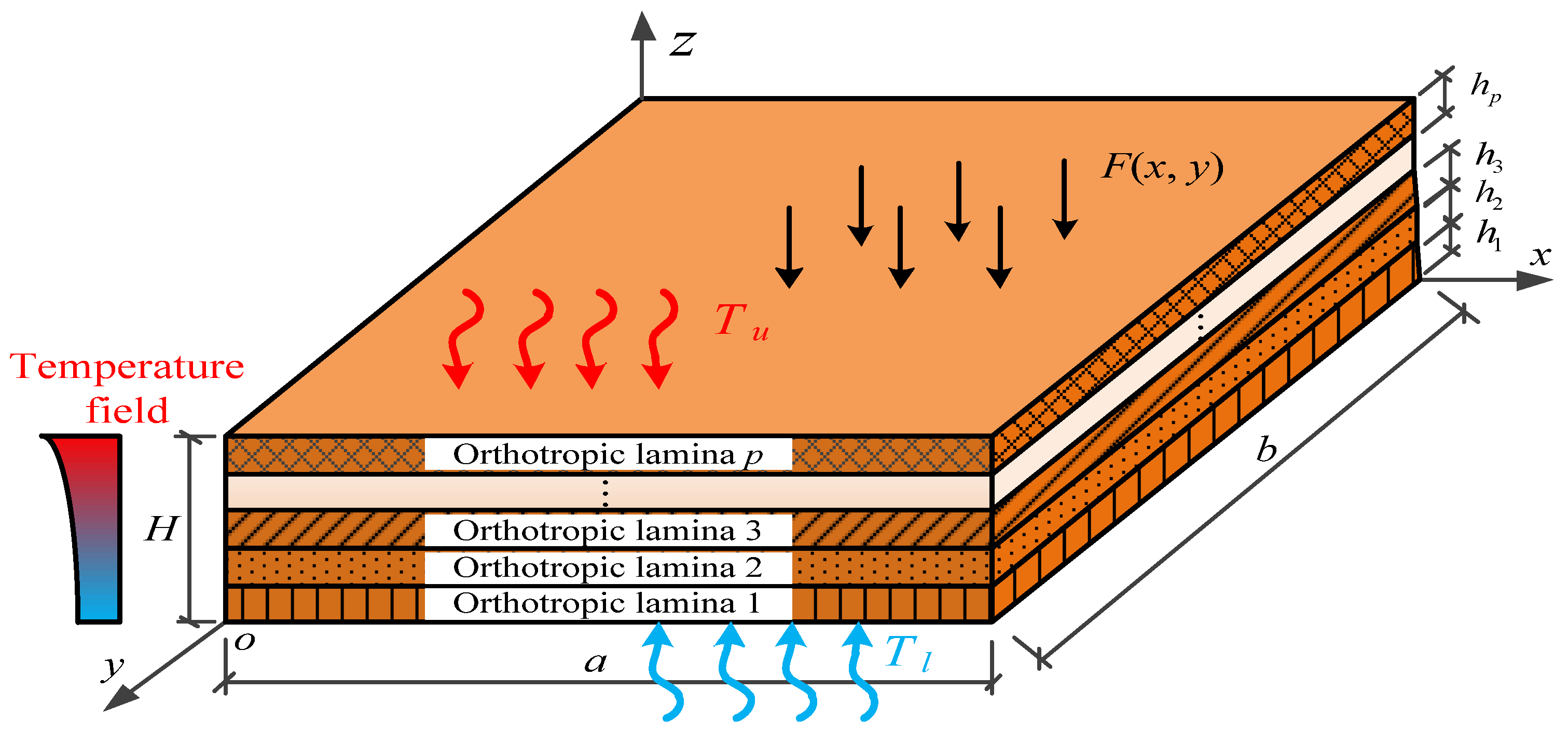
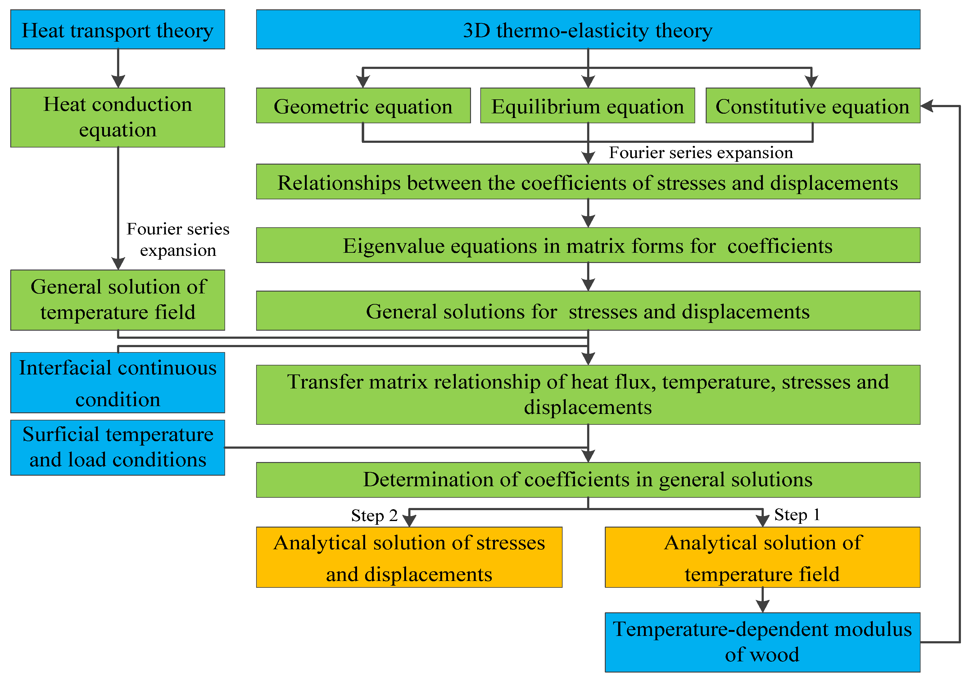
2. Analytical Model for CLT Panel

As illustrated in Figure 1, the subject under investigation is a CLT panel of length a, width b, and total thickness H in Cartesian coordinate system o-xyz, composed of p wood laminae each with thickness hi. The panel is simply supported at its four edges, bears a load F(x,y) on its upper surface, and is subjected to relative temperatures ΔTu and ΔTl on the upper and lower surfaces with respect to the ambient temperature T0, respectively. The temperature studied here only causes thermal deformation and affects the temperature-dependent modulus of wood, but is not sufficient to induce carbonization or combustion in the wood.

2.1. General Solutions of Temperature Field

The initial step in addressing the thermo-mechanical coupling problem of the CLT panel involves determining its temperature field. Utilizing heat transport theory [33], the heat conduction equation for the ith (i = 1, 2, p) lamina of the CLT panel is expressed as follows:
2 Δ T i x 2 + 2 Δ T i y 2 + 2 Δ T i z 2 = 0 ,
where Δ T i denotes the relative temperature of the ith wood lamina with respect to T0. Equation (1) is actually a partial differential equation which is hard to solve directly, and here Δ T i is expanded into a Fourier series in the x and y directions:
Δ T i = m = 1 n = 1 Δ T m n i ( z ) sin ( α m x ) sin ( β n y ) ,
where α m = m π / a , β n = n π / b . By substituting Equation (2) into Equation (1) and eliminating the trigonometric functions, the partial differential equation transforms into an ordinary differential equation:
d 2 Δ T m n i ( z ) d z 2 ( α m 2 + β n 2 ) T m n i ( z ) = 0 .
The general solution of the temperature field is
Δ T m n i ( z ) = e η 1 i m n z t 1 i m n + e η 2 i m n z t 2 i m n .
where η 1 i m n , η 2 i m n = ± ( α m 2 + β n 2 ) , and t 1 i m n and t 2 i m n are two undetermined coefficients.
The z-direction heat flux, denoted by F z i , is related to the temperature field as follows:
F z i = λ i Δ T i z ,
where λ i is the thermal conductivity coefficient of the ith lamina. Therefore, the general solutions for the temperature field and heat flux are prearranged in matrix form:
Δ T m n i F z , m n i = D m n i e η i m n z t i m n ,
where
D m n i = 1 1 λ i η 1 i m n λ i η 2 i m n , e η i m n z = e η 1 i m n z 0 0 e η 2 i m n z ,   t i m n = t 1 i m n t 2 i m n .

2.2. Temperature-Dependent Properties

The mechanical properties of wood degrade at high temperatures. According to the wood handbook [34], the temperature-dependent modulus of wood has the following relationship:
E ( T ) = E 0 ϕ ( T ) ,   ϕ ( T ) = 1.043097 0.0019944 T ,
where E 0 means the modulus at the ambient temperature (T0 = 21 °C), T means absolute temperature with T = Δ T + T0, and ϕ ( T ) represents the temperature influence factor.
According to the three-dimensional (3D) thermo-elasticity theory for orthotropic materials [35], the constitutive equation for the ith wood lamina is given by
σ x i σ y i σ z i = c 11 i c 12 i c 13 i c 12 i c 22 i c 23 i c 13 i c 23 i c 33 i ε x i ε y i ε z i φ x i φ y i φ z i T i ,   φ x i φ y i φ z i = c 11 i c 12 i c 13 i c 12 i c 22 i c 23 i c 13 i c 23 i c 33 i α 1 i α 2 i α 3 i , τ y z i = c 44 i γ y z i ,   τ x z i = c 55 i γ x z i ,   τ x y i = c 66 i γ x y i ,
where σ , τ , ε , and γ represent the normal stress, shear stress, normal strain, and shear strain, respectively; α is the thermal expansion coefficient; and c, the temperature-dependent stiffness coefficient, is expressed in terms of the modulus and Poisson’s ratio at T0 and the temperature influence factor, as follows
c 11 i = 1 ϕ 23 i ϕ 32 i E 2 i E 3 i Δ i ϕ ( T i ) ,   c 12 i = μ 12 i + μ 13 i μ 32 i E 1 i E 3 i Δ i ϕ ( T i ) ,   c 13 i = μ 13 i + μ 12 i μ 23 i E 1 i E 2 i Δ i ϕ ( T i ) , c 22 i = 1 μ 13 i μ 31 i E 1 i E 3 i Δ i ϕ ( T i ) ,   c 23 i = μ 23 i + μ 21 i μ 13 i E 1 i E 2 i Δ i ϕ ( T i ) ,   c 33 i = 1 μ 12 i μ 21 i E 1 i E 2 i Δ i ϕ ( T i ) , c 44 i = G 23 i ϕ ( T i ) ,   c 55 i = G 13 i ϕ ( T i ) ,   c 66 i = G 12 i ϕ ( T i ) , Δ i = 1 E 1 i μ 21 i E 2 i μ 31 i E 3 i μ 12 i E 1 i 1 E 2 i μ 32 i E 3 i μ 13 i E 1 i μ 23 i E 2 i 1 E 3 i .
The subscripts 1, 2, and 3 in the stiffness coefficients represent the x, y, and z directions, respectively, and correspondingly relate to the longitudinal (L), radial (R), and tangential (T) directions of the wood. Specifically, if the longitudinal direction of a wood lamina is parallel to the x-axis, the relationship is 1-L, 2-T, 3-R. Conversely, if the longitudinal direction of a wood lamina is perpendicular to the x-axis, the relationship becomes 1-T, 2-L, 3-R.

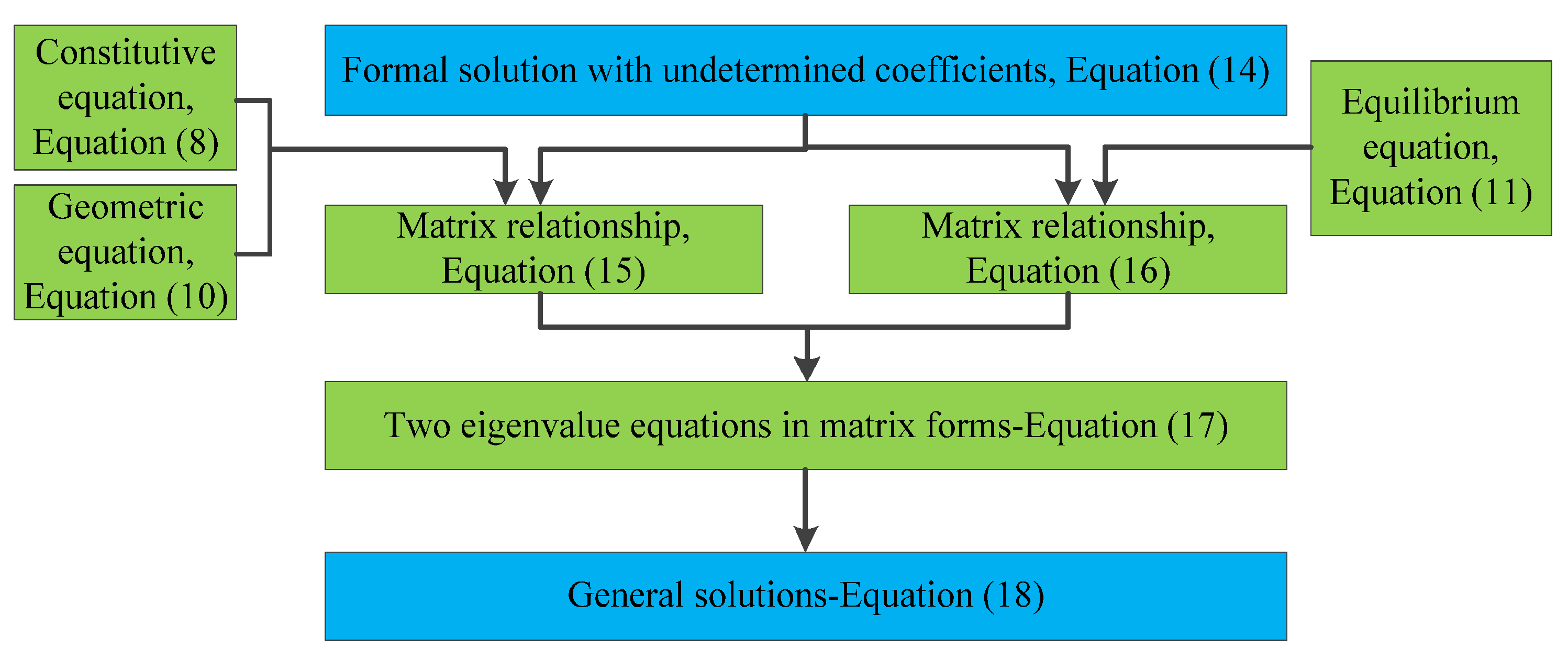
2.3. General Solutions of Stresses and Displacements

The next step is to solve the general solutions of stresses and displacements in the CLT panel under the thermo-mechanical coupling condition. Besides the constitutive equation, the stresses and displacements in the ith wood lamina are also governed by geometric and equilibrium equations [36], as follows
ε x i = u i x , ε y i = v i y , ε z i = w i z , γ y z i = v i z + w i y , γ x z i = u i z + w i x , γ x y i = u i y + v i x
σ x i x + τ x y i y + τ x z i z = 0 , σ y i y + τ x y i x + τ y z i z = 0 , σ z i z + τ x z i x + τ y z i y = 0 .
The boundary conditions of the simply supported CLT panel can be expressed by
σ x i = v i = w i = 0 ,   at   x   =   0 ,   a σ y i = u i = w i = 0 ,   at   y   =   0 ,   b
In order to avoid directly solving the above partial differential equations, according to Equation (12)’s boundary conditions, the stresses and displacements are expanded in a Fourier series as follows:
u i v i w i = m = 1 n = 1 u m n i ( z ) cos ( α m x ) sin ( β n y ) v m n i ( z ) sin ( α m x ) cos ( β n y ) w m n i ( z ) sin ( α m x ) sin ( β n y ) , τ x z i τ y z i σ z i = m = 1 n = 1 τ x z , m n i ( z ) cos ( α m x ) sin ( β n y ) τ y z , m n i ( z ) sin ( α m x ) cos ( β n y ) σ z , m n i ( z ) sin ( α m x ) sin ( β n y ) , σ x i σ y i τ x y i = m = 1 n = 1 σ x , m n i ( z ) sin ( α m x ) sin ( β n y ) σ y , m n i ( z ) sin ( α m x ) sin ( β n y ) τ x y , m n i ( z ) cos ( α m x ) cos ( β n y ) .
It can be found that after expanding into Fourier series, it can exactly satisfy Equation (12)’s boundary conditions.
Through the previous study of solving the analytical solutions of stress and displacement by solving equations [20], it is found that the solutions of the governing equations take the form of exponential functions; therefore, they can further be expressed into the formal solution, as follows:
D i m n = u m n i ( z ) v m n i ( z ) w m n i ( z ) = e s i m n z f 1 i m n f 2 i m n f 3 i m n + e η i m n z ψ 1 i m n ψ 2 i m n ψ 3 i m n , S i m n = τ x z , m n i ( z ) τ y z , m n i ( z ) σ z , m n i ( z ) = e s i m n z g 1 i m n g 2 i m n g 3 i m n + e η i m n z ρ 1 i m n ρ 2 i m n ρ 3 i m n , I i m n = σ x , m n i ( z ) τ x y , m n i ( z ) σ y , m n i ( z ) = e s i m n z ς 1 i m n ς 2 i m n ς 3 i m n + e s i m n z ζ 1 i m n ζ 2 i m n ζ 3 i m n ,
where s i m n , f * i m n , g * i m n , ψ * i m n , ρ * i m n , ς * i m n , and ζ * i m n are undetermined coefficients, while η i m n is known in Equation (4); D i m n and S i m n represent the out-of-plane stresses and displacements, while I i m n represents the in-plane ones.
By substituting Equations (6) and (14) into the governing equations of Equations (8), (10), and (11) and then eliminating the trigonometric functions as well as the exponential functions, the relationships between the coefficients of stresses and displacements are obtained:
g i m n = ( Ω i m n t + s i m n Ψ i ) f i m n , ρ i m n = ( Ω i m n t + η i m n Ψ i ) ψ i m n γ 2 i .
[ Θ i m n + s i m n ( Ω i m n Ω i m n t ) + ( s i m n ) 2 Ψ i ] f i m n = 0 , [ Θ i m n + η i m n ( Ω i m n Ω i m n t ) + ( η i m n ) 2 Ψ i ] ψ i m n = γ 1 i + η i m n γ 2 i ,
where
g i m n = g 1 i m n g 2 i m n g 3 i m n ,   ρ i m n = ρ 1 i m n ρ 2 i m n ρ 3 i m n ,   f i m n = f 1 i m n f 2 i m n f 3 i m n ,   ψ i m n = ψ 1 i m n ψ 2 i m n ψ 3 i m n , Ω i m n = 0 0 α m c 13 i 0 0 β n c 23 i α m c 55 i β n c 44 i 0 ,   Ψ i = c 55 i 0 0 0 c 44 i 0 0 0 c 33 i ,   γ 2 i = 0 0 φ z i . Θ i m n = ( c 11 i α m 2 + c 66 i β n 2 ) α m β n ( c 12 i + c 66 i ) 0 α m β n ( c 12 i + c 66 i ) ( c 66 i α m 2 + c 22 i β n 2 ) 0 0 0 ( c 55 i α m 2 + c 44 i β n 2 ) ,   γ 1 i = α m φ x i β n φ y i 0 .
Furthermore, Equation (16) can be organized into two eigenvalue equations in matrix forms:
N i m n V i m n = s i m n V i m n , N i m n U i m n = η i m n U i m n + γ i m n ,
where
N i m n = Ψ i 1 Ω i m n t Ψ i 1 Θ i m n Ω i m n Ψ i 1 Ω i m n t Ω i m n Ψ i 1 ,   V i m n = f i m n g i m n ,   U i m n = ψ i m n ρ i m n , γ i m n = 0 Ψ i 1 1 Ω i m n Ψ i 1 γ 1 i γ 2 i
Thus, the general solutions for the out-of-plane stresses and displacements are obtained from the above eigenvalue equations, as follows:
D i m n S i m n = V i m n e s i m n z C i m n + U i m n e s i m n z t i m n ,
where
e s i m n z = e s 1 i m n z 0 0 0 0 e s 2 i m n z 0 0 0 0 0 0 0 0 e s 6 i m n z
V i m n contains the six eigenvectors corresponding to the first eigenvalue equation of Equation (17), s j i m n are the six eigenvalues corresponding to the eigenvectors in V i m n , U i m n contains the two eigenvectors corresponding to the second eigenvalue equation of Equation (17), and t i m n and C i m n are undetermined vectors. A flowchart about the above eigenvalue method is shown in Figure 2.

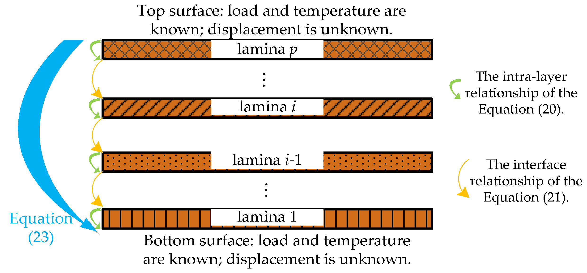
2.4. Determination of Coefficients

In this section, the undetermined coefficients in the general solutions are determined based on the interfacial relationships and the surface conditions. By substituting the z-coordinate value of the lower surface of the ith lamina into Equations (6) and (18), eliminating t i m n and C i m n , one obtains
D i m n S i m n Δ T m n i F z , m n i = A i ( z z i ) B i ( z z i ) 0 2 × 6 C i ( z z i ) D i m n S i m n Δ T m n i F z , m n i z = z i 1 ,
where
z i = j = 1 i h j ,   A i ( z z i ) = V i m n e s i m n ( z z i 1 ) ( V i m n ) 1 , B i ( z z i ) = U i m n e η i m n ( z z i 1 ) ( D m n i ) 1 A i ( z z i ) U i m n ( D m n i ) 1 , C i ( z z i ) = D m n i e η i m n ( z z i 1 ) ( D m n i ) 1 .
The interfacial relationships involving the temperature field, heat flux, stresses, and displacements between the adjacent laminae are expressed as follows
u m n i ( z ) = u m n i 1 ( z ) ,   v m n i ( z ) = v m n i 1 ( z ) ,   w m n i ( z ) = w m n i 1 ( z ) , τ x z , m n i ( z ) = τ x z , m n i 1 ( z ) ,   τ y z , m n i ( z ) = τ y z , m n i 1 ( z ) ,   σ z , m n i ( z ) = σ z , m n i 1 ( z ) , Δ T m n i = Δ T m n i 1 ,   F z , m n i = F z , m n i 1   z = z i 1
The above interface relationships can be reorganized into a matrix form
D i , m n S i , m n Δ T m n i F z , m n i z = z i 1 = D i 1 , m n S i 1 , m n Δ T m n i 1 F z , m n i 1 z = z i 1 ,
By reusing Equations (19) and (21), as shown in Figure 3, the transfer matrix relationship of heat flux, temperature, stresses, and displacements between the ith lamina and the first lamina is obtained as follows
D i m n S i m n Δ T u m n F z , m n i = E i ( z z i 1 ) E i 1 ( h i 1 ) E 1 ( h 1 ) D 1 , m n S 1 , m n Δ T 1 m n F z , m n 1 z = 0 ,
where
E i ( z z i ) = A i ( z z i ) B i ( z z i ) 0 2 × 6 C i ( z z i ) .
A direct relationship between the top and bottom surfaces of the whole CLT panel is obtained by taking i = p and z = H in Equation (22)
D p , m n S p , m n Δ T u m n F z , m n p z = H = Φ 11 Φ 12 Φ 21 Φ 22 D 1 , m n S 1 , m n Δ T l m n F z , m n 1 z = 0 ,
where
Φ 11 Φ 12 Φ 21 Φ 22 = E p ( h p ) E p 1 ( h p 1 ) E 1 ( h 1 ) ,
Φ 11 , Φ 12 , Φ 21 , Φ 22 are 3 × 3, 3 × 5, × 3, 5 × 5 matrices, respectively. The surficial load and temperature are known as
S p , m n ( H ) = 0 0 q m n = 4 a b 0 a 0 b F ( x , y ) sin ( α m x ) sin ( β n y ) d x d y ,   S 1 , m n ( 0 ) = 0 0 0 .
From Equation (23), the displacements at the bottom surface of the CLT beam can be obtained as
D 1 , m n ( 0 ) = ( Φ 21 ) 1 S p , m n Δ T u m n F z , m n p Φ 22 S 1 , m n Δ T l m n F z , m n 1 .
By substituting D 1 , m n ( 0 ) back into Equation (22), the analytical solution of the out-of-plane stress and displacement fields of the CLT panel under thermo-mechanical conditions are obtained finally. Then, the coefficients in the in-plane stresses can be determined by the relationship derived from Equations (8), (10), and (11):
ζ 1 i m n ζ 2 i m n ζ 3 i m n = c 11 i α m c 12 i β n c 13 i η i m n c 66 i β n c 66 i α m 0 c 12 i α m c 22 i β n c 23 i η i m n ψ 1 i m n ψ 2 i m n ψ 3 i m n φ x i 0 φ y i .
Figure 4 gives the flow diagram for the present analytical process.
The theoretical analytical model proposed above applies to laminates with anisotropic or isotropic properties at each layer, whether in other engineered wood products or in sustainable construction, such as glue-laminated timber.
It is essential to highlight that the present analytical solution is versatile and can be applied to a range of boundary conditions. For example, fixed boundary conditions can be compared to a scenario resembling a simply supported structure subjected to a horizontal force. The magnitude of this force can be precisely determined by the lack of deformation at the fixed edge [37]. In contrast, for free boundaries, the deformation components are a combination of Fourier series derived from simply supported boundary conditions and additional deformation functions, which are characterized by the absence of stress at the free edge [38].

3. Example Analysis and Discussion

In this section, the results from the proposed model are compared with established counterparts, and the bending behavior of the CLT panel under thermo-mechanical coupling conditions is investigated using different parameters. In the following analysis, the default research object is a five-layer CLT panel with geometric parameters set as a = b = 3000 mm, hi = 30 mm, unless otherwise specified, and the material properties of component woods of the CLT panel are listed in Table 1, unless otherwise specified. The ambient temperature is fixed at T0 = 21 °C.
For the decoupling analysis, Table 2 defines four actions, including pure mechanical (PM) load in cases 1 and 2 (C1 and C2), pure temperature (PT), mechanical-thermal (MT) action, in which C1 represents that only the load effect is considered, while C2 considers the temperature-dependent modulus of wood.

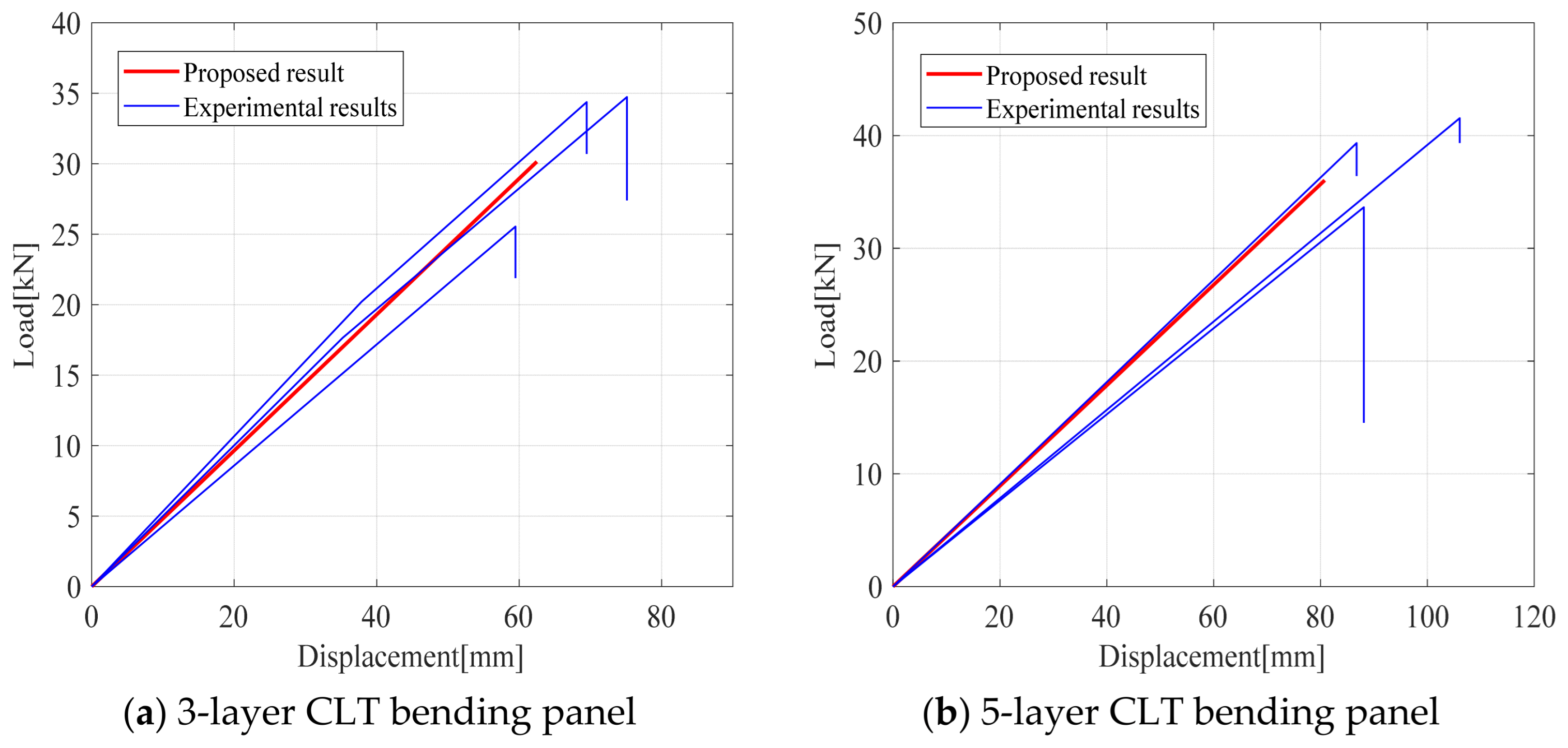
3.1. Comparison Study

To validate the correctness, a comparison is made between the proposed solution and the experimental results. Ref. [39] conducted comprehensive bending tests on both three-layer and five-layer CLT panels crafted from Canadian black spruce. Specifically, the three-layer panels measured 3300 mm in length with a 35/35/35 mm lamination, while the five-layer panels were 4800 mm long with a 35/25/35/25/35 mm lamination. Both types of panels were evaluated for their bending performance in the main strength direction. During the tests, loading points were positioned at the center, spaced six times the thickness of the CLT, and a constant displacement rate of 6.4 mm/min was applied. In Figure 5, the proposed results are compared with experimental ones of three-layer and five-layer CLT panels, with each consisting of three repetitive experiments. It is found that the proposed results are close to the experimental data. Specifically, the maximum discrepancies for the three-layer and five-layer panels amount to 11.42% and 15.3%, respectively.
In addition, the proposed solution is compared with the solution based on classical plate theory (CPT) [40] and the finite element (FE) solution provided by ABAQUS, in which the CPT solution is based on the plane section assumption. In the FE model, the element size has been precisely set to 0.01 m, with automatic meshing performed in ABAQUS. Also, the thermal field is calculated first by using the DC3D8 element, and then the thermo-mechanical behavior is determined by the C3D8T element. The layers are interconnected through the tie constraint, ensuring the absence of any relative slippage or separation between them. Since both the proposed solution and the FE solution account for the anisotropy of wood as well as the thermo-mechanical effects, while the CPT solution in Ref. [40] only considers isotropy and loading effects, two research objects are examined in this study. Table 3 presents a comparison of the proposed solution with the CPT and FE solutions in both MT and PM actions for different values of a/H (where a = b). In the MT action, the research object is the default five-layer CLT panel, while in the PM action, it is a three-layer isotropic panel bonded by a thin interlayer with h1 = h3 = 50 mm, h2 = 0.4 mm, E1 = E3 = 55,000 MPa, E2 = 6.12 MPa. In can be observed from Table 3 that the proposed solution and the FE solution are very close, with errors less than 2.2%, while the proposed solution in analytical form offers superior computational efficiency, as it eliminates the need for mesh generation required by the FE method. When a/H = 20, the CPT solution closely matches the proposed solution. However, as a/H decreases, the error increases. This is due to the significant impact of transverse shear deformation at lower a/H values, where the plane section assumption introduces a relatively large error.

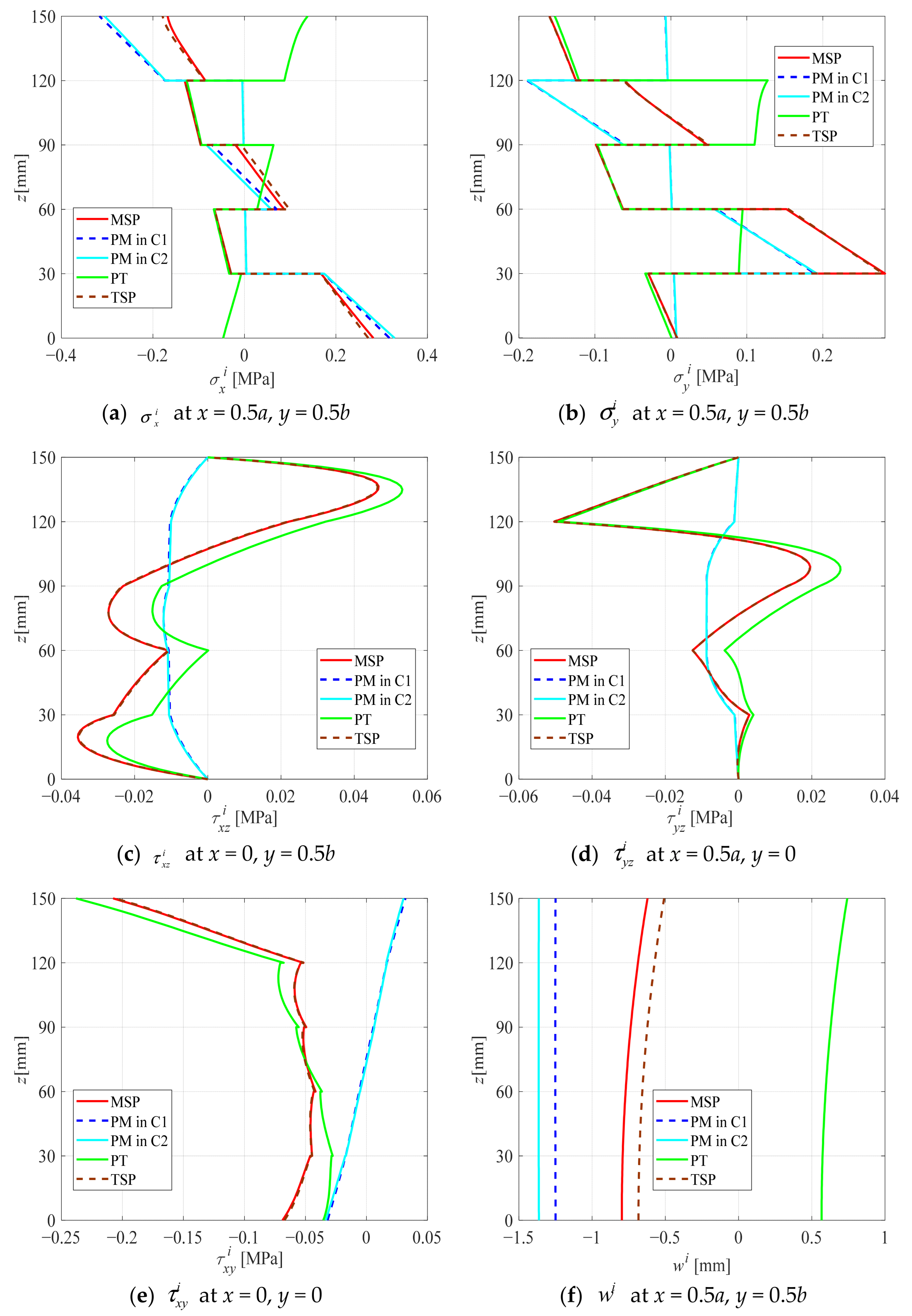
3.2. Decoupling Analysis and Modified Superposition Principle

The mechanical response of structural members under the thermo-mechanical condition is generally tackled by the superposition principle. Since the modulus of wood is temperature-dependent, especially at high temperatures, the applicability of the superposition principle in this context will be analyzed in this section. Figure 6 presents the distribution of stress and displacement along the thickness of the CLT panel formed by Balsa under the four kinds of action. Here, the load and temperature are taken as q(x) = 0.001 N/mm2 and ΔTu = 80 °C, ΔTl = 0 °C, to ensure that the numerical values of load effects and temperature effects are on the same order of magnitude. It can be found that (i) under PT and PM actions, the directions of stress and displacement are overall opposite. This is primarily due to the load causing the CLT panel to bend downward, while the temperature induces an upward bend in the panel. In this case, it can somewhat alleviate the stress and deformation of the CLT panel. (ii) In PM action, σ x i , σ y i , τ x y i , u i , and v i are anti-symmetric along the mid-plane z = 0.5H, while τ x z i , τ y z i , and w i are symmetric along the mid-plane. In PT action, there is no symmetry, and the stresses and displacements are large near the upper surface where the temperature is relatively high. (iii) In PM action, the maximums of σ x i and σ y i occur at the bottom or top surface of the panel, and τ x z i , τ y z i have their maximum at the mid-plane. Differently, in PT action, the maximum stresses occur at the interface of the adjacent laminae due to differential thermal expansion. (iv) By comparing the values of the four actions, two relationships are obtained:
Traditional superposition principle (TSP): PM in C1 + PT ≠ MT,
Modified superposition principle (MSP): PM in C2 + PT = MT,
MSP means that the stresses and displacements under the mechanical-thermal condition are the superposition of those in the pure temperature condition and those under mechanical load with considering the temperature-dependent mechanical property (PMC2). This means due to the temperature-dependent modulus of wood, the mechanical response of the CLT panel no longer strictly follows TSP. The error is mainly reflected in the displacement, with the maximum error in w reaching 18.27%. Meanwhile, the impact on stress is relatively small, with σ x having a larger influence, resulting in an error of 6.32%. The superposition principle requires modification to take into account the temperature-dependent modulus.

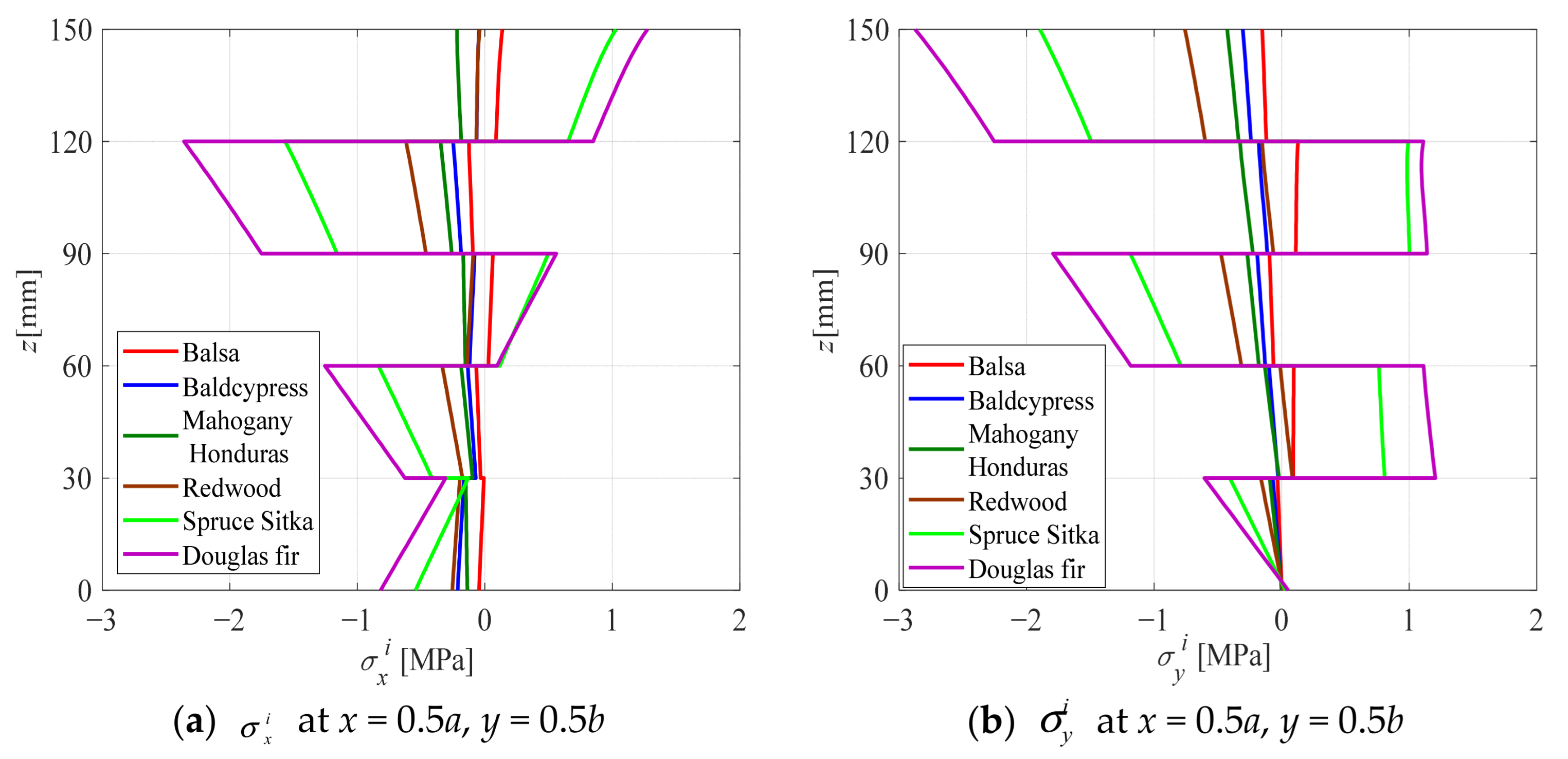
3.3. Influence of Wood Type

Figure 7 illustrates the distribution of thermal stresses and displacements along the z-direction in the CLT panel of six kinds of wood in PT action with ΔTu = 80 °C, ΔTl = 0 °C. It can be observed that the thermal stresses and displacements are more pronounced near the upper surface where the temperature is high, except that w i is less affected. Because of the disparity in modulus between the longitudinal and tangential directions, there are notable differences in the thermal stresses in odd-numbered and even-numbered laminae, with the thermal stress directions of adjacent laminae being predominantly opposed. It is evident that u i no longer remains planar along the thickness, indicating that this problem is not suitable for the plane section assumption. By comparing the differences of thermal stresses and displacements of the CLT panel made of six kinds of wood, it can be concluded that the thermal stresses and displacements mainly increase with absolute values of modulus E, G and the relative value of αL/αT. Specifically, σ x and τ x z are mainly influenced by the elastic modulus in the x-direction, the difference in elastic modulus in the x-direction between adjacent layers, and the thermal expansion coefficient in the x-direction. w, on the other hand, is primarily affected by the thermal expansion coefficient in the x-direction and the difference in thermal expansion coefficients in the x-direction between adjacent layers.

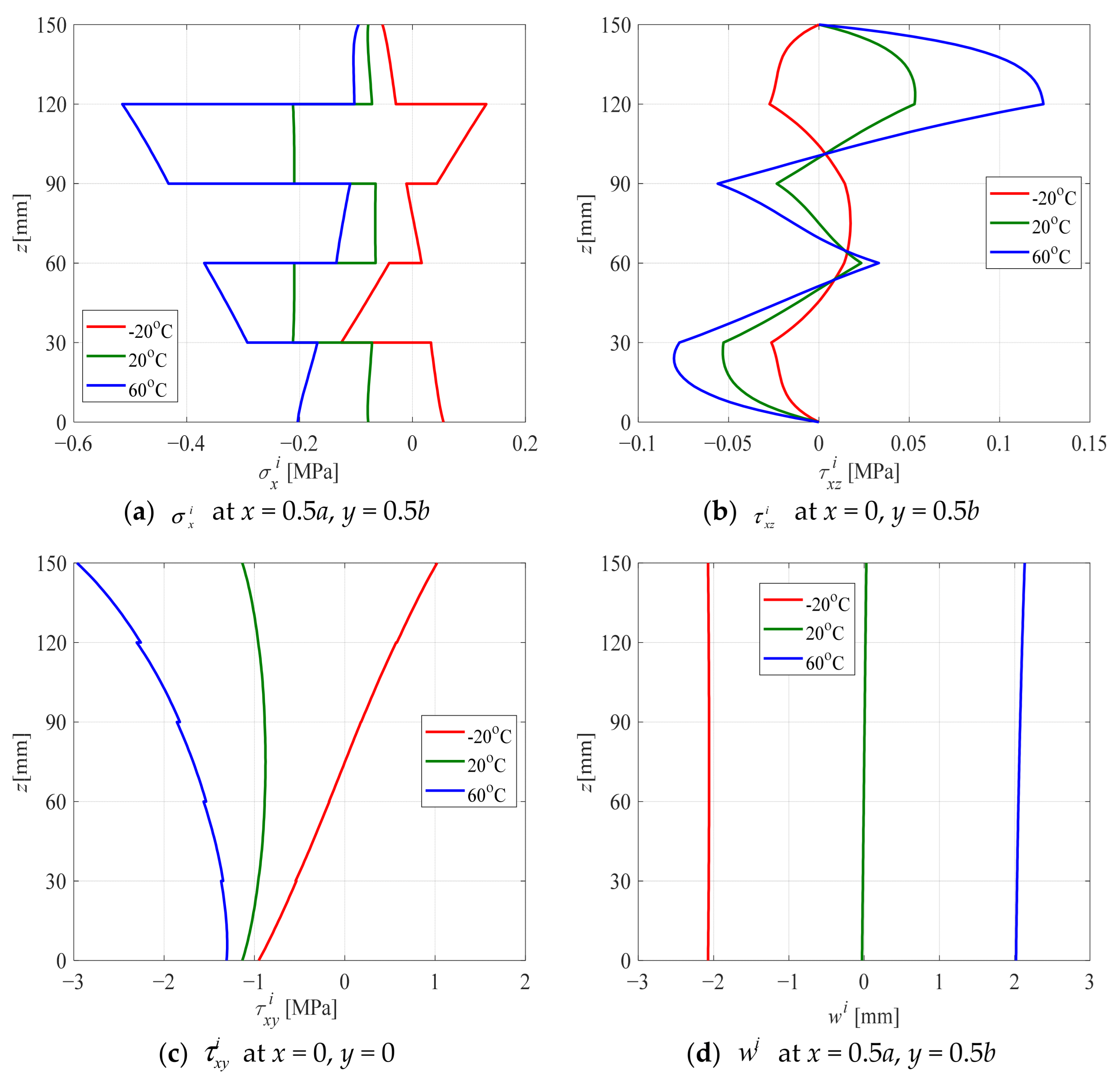
3.4. Influence of Temperature Difference

Figure 8 illustrates the distribution of z-direction thermal stresses and displacements in the CLT panel made of redwood in PT action with three kinds of temperature differences, i.e., ΔTu = −20, 20, 60 °C, respectively, ΔTl = 20 °C. It can be observed that when the temperature field is symmetric (ΔTu = ΔTl) along the mid-plane z = H/2, σ x i , τ x y i are also symmetric, while τ x z i , w i are anti-symmetric. For anti-symmetric temperature distribution, the symmetry laws governing thermal stresses and displacements are completely opposite. The results in PT action also have the superposition principle.
The thermal stress and displacement observed at ΔTu = 20 °C can be approximately equal to the mean values obtained at ΔTu = −20 °C and ΔTu = 60 °C; however, the error exists because the mechanical property of wood is temperature-dependent, as elucidated by the prior analysis of the superposition principle. However, a small error exists, because the modulus varies at different temperatures.

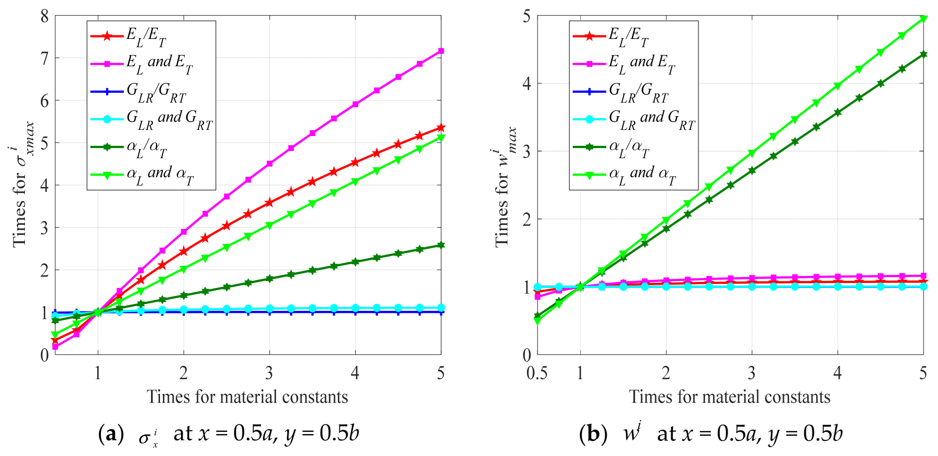
3.5. Influence of Material Constants

Consider a five-layer CLT panel made of Baldcypress with a × b × H = 3000 × 3000 × 150 mm3, where each layer has the same thickness. Figure 9 depicts the effects of the material constants of the CLT panel, including E L , E T , E L / E T , G L R / G R T , G L R , G R T , α L / α T , α L , α T , on the maximum stress and deflection, denoted by σ x max i and w max i in PT action. It can be observed that the influencing factors on σ x max i , in descending order of magnitude, are E L and E T , E L / E T , α L and α T , α L / α T , while G L R / G R T , G L R and G R T have little impact on σ x max i . w max i is mainly affected by α L , α T and α L / α T , while it is less affected by modulus. The extent to which these mechanical and thermal parameters influence CLT panels offers valuable insights for the practical design and optimization of laminated timber.

4. Conclusions

To investigate the bending behavior under thermo-mechanical conditions, an eigenvalue method based on 3D thermo-elasticity theory is proposed to derive an analytical solution. The concluding remarks can be summarized as follows:
  • The proposed results are close to the experimental ones. The proposed solution aligns well with the finite element results while providing superior computational efficiency. For thinner panels, the solution based on the plane section assumption closely matches the proposed solution; however, discrepancies increase as the panel thickness increases.
  • If the temperature at the top surface of the CLT panel is higher than at the bottom, the directions of stress and displacement are generally opposite. This is primarily because the load causes the CLT panel to bend downward, while the temperature difference induces an upward bend. In this case, it can somewhat alleviate the stress and deformation of the CLT panel.
  • For load effects, the stresses and displacements exhibit symmetry or anti-symmetry along the mid-plane of the CLT panel. In contrast, for temperature effects, the stresses and displacements are significantly larger near the upper surface, where the temperature is relatively high.
  • For different types of wood, thermal stress and displacement are more pronounced near the high-temperature surface, and the directions of thermal stress in adjacent layers are predominantly opposite. Moreover, the thermal stresses mainly increase with absolute values of modulus E, G and the relative value of αL/αT.
  • When the temperature field is symmetric along the mid-plane z = H/2, the thermal stress and displacement components exhibit either symmetric or anti-symmetric behavior. However, for an anti-symmetric temperature distribution, the symmetry rules governing thermal stress and displacement are entirely reversed.
  • The influencing factors on the normal stress, in descending order of magnitude, are the elastic modulus and thermal expansion coefficients, while shear modulus has little impact on the normal stress. Deflection is mainly affected by thermal expansion coefficients, while it is less affected by modulus.
This analytical method serves as an efficient tool for CLT structural design, enabling separate analysis under combined temperature loads via a modified superposition principle. It also can quickly reveal parameter impacts on stress and displacement, guiding engineering practice.

Author Contributions

Methodology, P.W.; software, Z.X.; validation, S.L.; investigation, C.L.; data curation, K.Y.; writing—original draft preparation, C.L.; writing—review and editing, S.L.; visualization, B.S.; supervision, P.W. All authors have read and agreed to the published version of the manuscript.

Funding

This work has been supported by the 2023 Jiangsu Province Higher Education Basic Science (Natural Science) Research General Project (Grant NO. 23KJB220010), 2023 Jiangsu Province Housing and Construction System Technology Project (Grant NO. 2023ZD046), 2023 Yangzhou Housing and Construction System Technology Project (Grant NO. 2023JH04), Jiangsu University Blue Project Funding.

Data Availability Statement

Data will be made available on request.

Conflicts of Interest

The authors declare that they have no known competing financial interests or personal relationships that could have appeared to influence the work reported in this paper.

References

  1. Lineham, S.A.; Thomson, D.; Bartlett, A.I.; Bisby, L.A.; Hadden, R.M. Structural response of fire-exposed cross-laminated timber beams under sustained loads. Fire Saf. J. 2016, 85, 23–34. [Google Scholar] [CrossRef]
  2. Yang, Z.Y.; Zhu, H.; Yu, F.; Wu, P.; Fang, H. Thermo-mechanical coupled behavior of laminated beams with temperature-dependent viscoelastic interlayers. Eur. J. Mech. A-Solids 2023, 100, 105000. [Google Scholar] [CrossRef]
  3. Sciomenta, M.; Bedon, C.; Fragiacomo, M. Experimental and Numerical Column Buckling Analysis of Hardwood Cross-Laminated Timber Panels. J. Struct. Eng. 2024, 150, 04024030. [Google Scholar] [CrossRef]
  4. Xu, B.H.; Zhang, S.D.; Zhao, Y.H.; Bouchair, A.; Zhang, B.S. Mechanical Properties of Adhesive-Free Cross-Laminated Timber. J. Struct. Eng. 2022, 148, 04022135. [Google Scholar] [CrossRef]
  5. Boccadoro, L.; Zweidler, S.; Steiger, R.; Frangi, A. Bending tests on timber-concrete composite members made of beech laminated veneer lumber with notched connection. Eng. Struct. 2017, 132, 14–28. [Google Scholar] [CrossRef]
  6. Li, H.; Wang, L.B.; Wei, Y.; Wang, B.J.; Jin, H. Bending and shear performance of cross-laminated timber and glued-laminated timber beams: A comparative investigation. J. Build. Eng. 2022, 45, 103477. [Google Scholar] [CrossRef]
  7. Santos, P.; Correia, R.; Godinho, L.; Dias, A.M.P.G.; Craveiro, H. Experimental and numerical assessment of a cross-insulated timber panel solution. Eng. Struct. 2021, 235, 112061. [Google Scholar] [CrossRef]
  8. Mindeguia, J.C.; Mohaine, S.; Bisby, L.; Robert, F.; McNamee, R.; Bartlett, A. Thermo-mechanical behaviour of cross-laminated timber slabs under standard and natural fires. Fire Mater. 2020, 45, 866–884. [Google Scholar] [CrossRef]
  9. Pieniak, D.; Ogrodnik, P.; Oszust, M.; Niewczas, A. Reliability of the thermal treated timber and wood-based materials in high temperatures. Eksploat. I Niezawodn.-Maint. Reliab. 2013, 15, 18–24. [Google Scholar]
  10. Santos, P.; Sousa, L.; Godinho, L.; Correia, J.R.; Dias, A.M.P.G. Acoustic and thermal behavior of cross-insulated timber panels. J. Build. Eng. 2021, 44, 103309. [Google Scholar] [CrossRef]
  11. Fragiacomo, M.; Menis, A.; Clemente, I.; Bochicchio, G.; Ceccotti, A. Fire Resistance of Cross-Laminated Timber Panels Loaded Out of Plane. J. Struct. Eng. 2013, 139, 12. [Google Scholar] [CrossRef]
  12. Kytka, T.; Gasparík, M.; Sahula LKarami, E.; Teterin, D.; Das, S.; Novák, D.; Kvietková, M.S. Bending characteristics of glued laminated timber depending on the alternating effects of freezing and heating. Constr. Build. Mater. 2022, 350, 128916. [Google Scholar] [CrossRef]
  13. Chorlton, B.; Gales, J. Mechanical performance of laminated veneer lumber and Glulam beams after short-term incident heat exposure. Constr. Build. Mater. 2020, 263, 120129. [Google Scholar] [CrossRef]
  14. Pulngern, T.; Udtaranakron, T.; Chanto, K. Physical and mechanical behaviors of thermally modified rubberwood glulam beam under sustained and cyclic loading. Wood Fiber Sci. 2020, 52, 298–312. [Google Scholar] [CrossRef]
  15. He, M.J.; Sun, X.F.; Ren, H.Q.; Li, Z.; Feng, W. Experimental study on the system effect of bending cross-laminated timber fabricated with Karamatsu larch. Constr. Build. Mater. 2021, 299, 124271. [Google Scholar] [CrossRef]
  16. Dong, W.C.; Colin, M.R.; Julia, A.S. Cross-laminated secondary timber: Validation of non-destructive assessment of structural properties by full-scale bending tests. Eng. Struct. 2024, 298, 117029. [Google Scholar] [CrossRef]
  17. Zhang, X.B.; Yang, S.Y.; Fei, B.H.; Qin, D.C.; Yang, J.; Li, H.P.; Wang, X.H. Bending and shear performance of a cross-laminated composite consisting of flattened bamboo board and Chinese fir lumber. Constr. Build. Mater. 2023, 392, 131913. [Google Scholar] [CrossRef]
  18. Nairn, J.A. Cross laminated timber properties including effects of non-glued edges and additional cracks. Eur. J. Wood Wood Prod. 2017, 75, 973–983. [Google Scholar] [CrossRef]
  19. Vega, C.R.; Pina, J.C.; Bosco, E.; Flores, E.I.S.; Guzman, C.F.; Yane, S.J. Thermo-mechanical analysis of wood through an asymptotic homogenization approach. Constr. Build. Mater. 2022, 315, 125617. [Google Scholar] [CrossRef]
  20. Li, C.; Li, S.C.; Yue, K.; Wu, P.; Xiao, Z.P.; Zhang, J. Analytical solutions and optimization design for bending behavior of cross-laminated timber beams considering orthotropy and interface slip. Case Stud. Constr. Mater. 2023, 18, e01948. [Google Scholar] [CrossRef]
  21. Kim, Y.; Davalos, J.F.; Barbero, E.J. Delamination buckling of FRP layer in laminated wood beams. Compos. Struct. 1997, 37, 311–320. [Google Scholar] [CrossRef]
  22. Wen, J.; Xiao, Y. The flexural behavior of cross laminated bamboo and timber (CLBT) and cross laminated timber (CLT) beams. Constr. Build. Mater. 2023, 408, 133739. [Google Scholar] [CrossRef]
  23. Huang, Z.R.; Huang, D.S.; Chui, Y.H.; Chen, Z.F. A layered beam-based model for analyzing the stress of rolling shear for the cross-laminated timber panels under out-of-plane bending. Eng. Struct. 2023, 289, 116290. [Google Scholar] [CrossRef]
  24. Fabrizio, C.; Sciomenta, M.; Spera, L.; De Santis, Y.; Pagliaro, S.; Di Egidio, A.; Fragiacomo, M. Experimental investigation and beam-theory-based analytical model of cross-laminated timber panels buckling behavior. Arch. Civ. Mech. Eng. 2023, 23, 172. [Google Scholar] [CrossRef]
  25. Chen, Z.Y.; Popovski, M. Mechanics-based analytical models for balloon-type cross-laminated timber (CLT) shear walls under lateral loads. Eng. Struct. 2020, 208, 109916. [Google Scholar] [CrossRef]
  26. Gangi, M.J.; Lattimer, B.Y.; Case, S.W. Scale modeling of thermo-structural fire tests of multi-orientation wood laminates. Wood Sci. Technol. 2024, 58, 1285–1322. [Google Scholar] [CrossRef]
  27. Huang, Z.R.; Bian, Y.L.; Ni, C. A rolling shear analysis-based method for determining the apparent stiffness and bending capacity of CLT panel under out-of-plane load. J. Wood Sci. 2024, 70, 1. [Google Scholar] [CrossRef]
  28. Wiesner, F.; Bisby, L.A.; Bartlett, A.I.; Hidalgo, J.P.; Santamaria, S.; Deeny, S.; Hadden, R.M. Structural capacity in fire of laminated timber elements in compartments with exposed timber surfaces. Eng. Struct. 2019, 179, 284–295. [Google Scholar] [CrossRef]
  29. La Scala, A.; Sliwa-Wieczorek, K.; Rizzo, F.; Sabbà, M.F.; Zajac, B. Flexible Polyurethane Adhesives: Predictive Numerical Model Calibration through Experimental Testing at Elevated Temperature. Appl. Sci. 2024, 14, 1943. [Google Scholar] [CrossRef]
  30. Fernandez-Cabo, J.L.; Diez-Barra, R.; Fernandez-Lavandera, J.; Avila-Jalvo, J.M. Timber composite beams with a discrete connection system. Proc. Inst. Civ. Eng.-Struct. Build. 2013, 166, 57–72. [Google Scholar] [CrossRef]
  31. Chen, Z.T.; Lu, W.D.; Bao, Y.W.; Zhang, J.; Wang, L.; Yue, K. Numerical Investigation of Connection Performance of Timber-Concrete Composite Slabs with Inclined Self-Tapping Screws under High Temperature. J. Renew. Mater. 2022, 10, 89–104. [Google Scholar] [CrossRef]
  32. Chiniforush, A.A.; Valipour, H.R.; Bradford, M.A.; Akbarnezhad, A. Long-term behaviour of steel-timber composite (STC) shear connections. Eng. Struct. 2019, 196, 109356. [Google Scholar] [CrossRef]
  33. Sellitto, A.; Cimmelli, V.A. A Continuum Approach to Thermomass Theory. J. Heat Transf.-Trans. ASME 2012, 134, 112402. [Google Scholar] [CrossRef]
  34. Peter, N.; Alfred, T.; Dick, S. Springer Handbook of Wood Science and Technology; Springer: Berlin/Heidelberg, Germany, 2023; ISSN 2522-8706. [Google Scholar]
  35. Adineh, M.; Kadkhodayan, M. Three-dimensional thermo-elastic analysis of multi-directional functionally graded rectangular plates on elastic foundation. Acta Mech. 2017, 228, 881–899. [Google Scholar] [CrossRef]
  36. Vasil’ev, V.V.; Lurie, S.A. Generalized theory of elasticity. Mech. Solids 2015, 50, 379–388. [Google Scholar] [CrossRef]
  37. Xu, Y.P.; Zhou, D.; Cheng, Y.K. Elasticity solution of clamped-simply supported beams with variable thickness. Appl. Math. Mech.-Engl. Ed. 2008, 29, 279–290. [Google Scholar] [CrossRef]
  38. Huang, B.; Chen, J.B.; Hua, L.C.; Yi, L.J.; Ma, T.F.; Wang, J.; Kim, H.S. A stress function based viscoelastic model for relaxation of free edge stresses in composite laminates. Compos. Struct. 2019, 232, 111581. [Google Scholar] [CrossRef]
  39. He, M.J.; Sun, X.F.; Li, Z.; Feng, W. Bending, shear, and compressive properties of three- and five-layer cross-laminated timber fabricated with black spruce. J. Wood Sci. 2020, 66, 38. [Google Scholar] [CrossRef]
  40. Foraboschi, P. Three-layered plate: Elasticity solution. Compos. Part B-Eng. 2014, 60, 764–776. [Google Scholar] [CrossRef]
Figure 1. Schematic diagram for CLT panel under thermo-mechanical coupling condition.
Buildings 15 00026 g001
Figure 2. Flow diagram for the eigenvalue method.
Buildings 15 00026 g002
Figure 3. Schematic diagram of transfer matrix relationship.
Buildings 15 00026 g003
Figure 4. Flow diagram for the present analytical process.
Buildings 15 00026 g004
Figure 5. Comparisons between experimental curves and numerical curve.
Buildings 15 00026 g005
Figure 6. Distribution of stress and displacement along the thickness of the CLT panel under the four kinds of action.
Buildings 15 00026 g006aBuildings 15 00026 g006b
Figure 7. Distribution of stress and displacement along the z-direction in the CLT panel of six kinds of wood in PT action.
Buildings 15 00026 g007aBuildings 15 00026 g007b
Figure 8. Distribution of z-direction thermal stresses and displacements in the CLT panel made of redwood in PT action with three kinds of temperature differences.
Buildings 15 00026 g008
Figure 9. Effects of material constants on σ x max i and w max i of CLT panel in PT action.
Buildings 15 00026 g009
Table 1. Material constants of six woods at 21 °C [34].
Material PropertySpruce SitkaDouglas FirBalsaBald CypressMahogany HondurasRedwood
EL11,88013,297.7374010,89011,33010,120
ET510.84664.8956.1427.71725.12900.68
ER926.64904.24172.04914.761212.31880.44
GLR760.32851.05201.96686.07747.78667.92
GLT724.681037.22138.38588.06974.38779.24
GRT35.6493.0818.776.23317.24111.32
μLR0.3720.2920.2290.3380.3140.36
μLT0.4670.4490.4880.3260.5330.346
μTL0.0250.0290.0090.0130.0340.031
μTR0.2450.3740.2310.3560.3260.4
λL3 × 10−43 × 10−48 × 10−51.2 × 10−41.5 × 10−41.1 × 10⁻⁴
λT1.2 × 10−41.2 × 10−45 × 10−51 × 10−41.2 × 10−41 × 10−4
λR1.3 × 10−41.1 × 10−45 × 10−51 × 10−41.2 × 10−41 × 10−4
αL4 × 10−65 × 10−61×10−75 × 10−64 × 10−66 × 10−6
αT6 × 10−57 × 10−54 × 10−51.5 × 10−51.2 × 10−51.8 × 10⁻⁵
αR3 × 10−53 × 10−52 × 10−51.1 × 10−51 × 10−51.4 × 10⁻⁵
Note: E stands for elastic modulus, G for shear modulus, μ for Poisson’s ratio, λ for thermal conductivity coefficient, and α for thermal expansion coefficient. The subscripts L, R, and T represent the longitudinal, radial, and tangential directions of the wood, respectively. The units of E, λ and α, are [MPa], [/°C] and [W/(mm·°C)], respectively.
Table 2. Definitions of the four actions.
ConditionLoad EffectThermal DeformationTemperature-Dependent
PM in C1
PM in C2
PT
MT
Table 3. Comparisons of the proposed solution with the CPT and FE solutions for different a/H.
a/HSolutionMT ActionPM Action
ProposedFEProposedCPTFE
7 σ x [MPa]−40.47−41.2815.9918.6616.12
σ y [MPa]−1.508−1.537---
τ x z [MPa]−4.101−4.175−0.1204−0.1200−0.1214
τ y z [MPa]−2.781−2.839---
w [mm]−41.12−41.86−0.4023−0.4628−0.4068
10 σ x [MPa]−77.52−79.0735.3736.7935.05
σ y [MPa]−2.312−2.266---
τ x z [MPa]−5.949−5.860−0.3260−0.3253−0.3286
τ y z [MPa]−4.118−4.204---
w [mm]−122.0−124.4−1.771−1.828−1.788
15 σ x [MPa]−172.0−175.376.6377.1375.86
σ y [MPa]−4.291−4.368---
τ x z [MPa]−9.038−9.192−0.9391−0.9373−0.9495
τ y z [MPa]−6.398−6.283---
w [mm]−479.6−474.3−8.252−8.277−8.326
20 σ x [MPa]−305.6−311.7116.4116.5117.3
σ y [MPa]−7.052−7.207---
τ x z [MPa]−12.10−12.33−1.647−1.643−1.667
τ y z [MPa]−8.739−8.923---
w [mm]−1360−1384−19.32−19.29−19.45
Note: the results of stresses and displacement are obtained at location σ x (0.5a, 0.5b, H), σ y (0.5a, 0.5b, H) τ x z (0, 0.5b, 0.5H), τ y z (0.5a, 0, 0.5H), w (0.5a, 0.5b, H).
Disclaimer/Publisher’s Note: The statements, opinions and data contained in all publications are solely those of the individual author(s) and contributor(s) and not of MDPI and/or the editor(s). MDPI and/or the editor(s) disclaim responsibility for any injury to people or property resulting from any ideas, methods, instructions or products referred to in the content.

