Article

Research on Rock-Breaking Characteristics of Cutters and Matching of Cutter Spacing and Penetration for Tunnel Boring Machine

1
Nanchang Rail Transit Group Limited Corporation, Nanchang 330038, China
2
State Key Laboratory of Intelligent Geotechnics and Tunnelling, Chengdu 610031, China
3
School of Civil Engineering, Southwest Jiaotong University, Chengdu 610031, China
*
Author to whom correspondence should be addressed.
Buildings 2024, 14(6), 1757; https://doi.org/10.3390/buildings14061757
Submission received: 9 May 2024 / Revised: 3 June 2024 / Accepted: 7 June 2024 / Published: 11 June 2024

Abstract

:
Tunnel boring machine (TBM) tunnel construction in composite strata relies heavily on understanding the rock-breaking characteristics of TBM cutters and optimizing cutter spacing and penetration. Utilizing a full-scale rock rotary cutting machine (RCM), this study conducted rock-breaking tests with disc cutters under varying rolling radii. An analysis of rock debris shape and cutter behavior provided insights into rock-breaking mechanisms. Two main types of rock fragments were identified, with both shear and compression failure observed during cutter–rock interactions. The influence of the rolling radius and cutter spacing on cutter forces was analyzed, along with numerical modeling using the particle flow method. Optimal cutter selection in soft–hard composite strata should prioritize cutter force, with the greatest force required in hard rock. Cutter force increases with penetration, while the force difference between cutters decreases with reduced cutter spacing. These findings offer practical guidance for efficient rock-breaking in composite geological formations during tunnel construction.

1. Introduction

Tunnel boring machines (TBMs) cause little disturbance to the stratum, have high tunneling efficiency, and are widely used in tunnel excavation construction [1,2]. It is easier to use TBM for tunnel construction in a homogeneous stratum such as soft soil and soft rock [3,4,5]. TBM excavation parameters and mode are relatively single and stable, and the construction technology is relatively simple. However, using TBM in soft–hard composite strata is prone to problems such as excessive wear and eccentric wear [6,7]. Improving the wear resistance and utilization rate of cutters through reasonable cutter selection and cutter spacing setting is one of the research focuses of TBM excavation in composite strata [8].
Various approaches, including numerical methods, theoretical or empirical models, and laboratory studies, have been employed to comprehend the rock-breaking process related to TBM excavation [9]. More and more researchers favor laboratory tests, particularly full-scale rock cutting tests, since they can accurately depict the interaction relationship between cutters and rocks. Rock linear cutting and rotary cutting tests are the two primary components of a typical full-scale rock cutting test. Geng et al. [10] used a full-scale rotary cutting machine to research the differences in rock cutting between the gage and normal cutters for TBM. They found that the gage cutter’s cutting forces and specific energy were smaller than the normal cutter’s. The impact of disc cutter installation radius on rock-cutting forces was investigated by Pan et al. [11]. According to Zhang et al. [12], Gertsch et al. [13], and Peng et al. [14], the cutter spacing affects the rock-breaking efficiency more significantly. Additionally, Gong et al. [15] investigated the distinctions between rotating and linear cutting and examined the effects of the two cutting methods on the cutter force and specific energy. A three-dimensional rock measuring system was presented by Cho et al. [16] to ascertain the ideal ratio of cutter spacing to penetration for effective rock breaking. They found that when the ideal cutter spacing is used, TBM efficiency may be increased by applying a stronger thrust force or a deeper penetration depth.
Numerous numerical methods, such as the finite difference method (FDM), discrete element method (DEM), and finite element method (FEM), have been used to investigate the rock fragmentation mechanisms during excavation by TBM disc cutters because laboratory testing is very expensive [17,18,19]. Gong et al. [20,21] used the two-dimensional discrete element program UDEC to investigate the impact of cutter spacing and rock joints on a cutter’s rock-breaking process. Using the particle discrete element approach, Zhang et al. [22] examined the impact of spacing on the rock-breaking properties of a double-edged center cutter. They discovered three different breaking modes as the cutter spacing and confining pressure varied. Wen et al. [23] studied the rock-breaking process of TBM disc cutters to investigate the performance of the cutters on composite rocks. They found an ideal ratio of cutter spacing to penetration depth for composite and homogeneous rocks. Also, Cho et al. [24] utilized the three-dimensional dynamic fracturing method to investigate the ideal TBM disc cutter spacing.
The impact of variables like penetration, surrounding rock, cutter spacing, and spacing on the effectiveness of rock-breaking has been extensively examined in these studies. The optimization of TBM cutterheads and disc cutter design and construction is well supported by these results. To analyze rock debris’s shape and rock-breaking characteristics, this study carried out several full-scale rock rotary cutting tests using a disc cutter under various rolling radii. At the same time, it can be found that there are many studies on the rock-breaking efficiency of TBM’s disc cutters on homogeneous rocks and few studies on composite rocks. Given the concerns above, this work developed numerical particle flow models to examine how multiple cutters in composite strata cause dynamic rock mass fracture. Finally, the relationship between rock mass cracks, penetrations, and cutter force during cutter intrusion was analyzed.

2. Experimental Apparatus and Procedures

2.1. Experimental System

The full-scale rotary cutting machine (RCM) can simulate the rock-breaking process of multiple disc cutters, as shown in Figure 1. The main technical parameters of the RCM are summarized in Table 1. The axial load is applied using an electro-hydraulic servo oil source, with power provided by a gear pump. An EDC full digital servo controller PID is used for closed-loop servo control of axial displacement and axial force. The axial displacement is measured using a cable-type grating fiber optic sensor, and the axial force is measured using a load sensor. To accurately control and reduce the lateral torque of the rolling cutter, the actuator adopts a low-friction rigid actuator.
The AC servo motor driver, reducer, and closed-loop servo controller control the precise rotation of rock samples. The AC servo motor adopts a high-frequency response variable frequency motor and an EDC servo controller for closed-loop servo control. The sensors used for data collection mainly consist of load sensors, cable-type grating fiber displacement sensors, torque sensors, frequency sensors, and rotational speed sensors.

2.2. Sample Preparation

The test’s rock samples are whole sandstones devoid of visible fractures. The core samples are sliced into a trapezium shape, making assembling the rock samples in the rock box easier. Figure 2 depicts how the rock samples are arranged inside the rock box. The concrete used to level the lower portion of the rock box is 100 mm high, and its mechanical characteristics are essentially the same as those of the rock sample. The same concrete is poured into the spaces between the rock samples and compacted by vibration once the rock samples have been fixed. The test is conducted four weeks after the cure.

2.3. Experimental Process

To conduct a series of rock-breaking experiments with various cutter rolling radii, a constant-section disc cutter with a diameter of 432 mm (17 inches) was chosen. This type of cutter is frequently employed in real engineering applications. The cutterhead had a penetration rate of 5 mm·min−1, a rotation speed of 1 r·min−1, and a penetration depth of 20 mm. The following was the test procedure:
(1)
Firstly, the installation radius of the rolling cutter was 0.45 m, and the cutterhead rotated four circles.
(2)
Secondly, the cutter was moved outward by 75 mm (R = 0.525 m), and the cutterhead rotated four circles.
(3)
Thirdly, the cutter was moved outward by 90 mm (R = 0.615 m), and the cutterhead rotated four circles.
(4)
Fourthly, the cutter was moved outward by 110 mm (R = 0.725 m), and the cutterhead rotated four circles.
(5)
Lastly, the cutter was moved outward by 130 mm (R = 0.855 m), and the cutterhead rotated four circles.
During every cutter rock-cutting process, the thrust and torque of the cutterhead were measured in real time. After every experiment, the rock surface was cleaned, and the size and mass of the rock debris were measured.

3. Experimental Results

3.1. Rock Debris Shape Analysis

Figure 3 shows the rock-breaking process of the cutter at various rotation radii. It is evident that three stages involve using a cutter to cut rock. Because of the rock’s strong integrity and the cutter’s small cutting load, stage I, also known as the local rock fragmentation stage, has a locally fragmented rock surface and a shallow rock pit depth. As the cutting load increases, the rocks close to the cutter’s action region start to fracture in sizable sections during stage II, also known as the severe rock fragmentation stage. Rock fragmentation sounds become more frequent, and some rock fragments splash out of the experimental platform. The rock fragmentation process is rather steady in stage III, also known as the stable rock fragmentation stage, with massive amounts of rock debris collapsing and breaking.
During the rolling process of the disc cutter, a large amount of rock powder is ejected from the wedge surface on both sides of the cutter tip, emitting a sound of rock fracture. Subsequently, many rock fragments collapse, and they can be divided into two types. Type I rock fragments exhibit a “one thick end and another thin end” shape. The fracture surface of the rock fragment is uneven and has sharp edges and corners. Type II rock fragments exhibit a “thin at both ends and thick in the middle” shape. Some rock fragments of this type still adhere to the parent rock without peeling off. It can be observed that the type I rock fragments are formed by crack propagation to the rock surface, and the type II rock fragments are formed due to overlapping adjacent rock-breaking areas by cutters, causing cracks to penetrate. Then, the broken rock peels off. The rock fragmentation morphology indicates that there is shear failure and compression failure in the rock during the process of the cutter breaking rock.

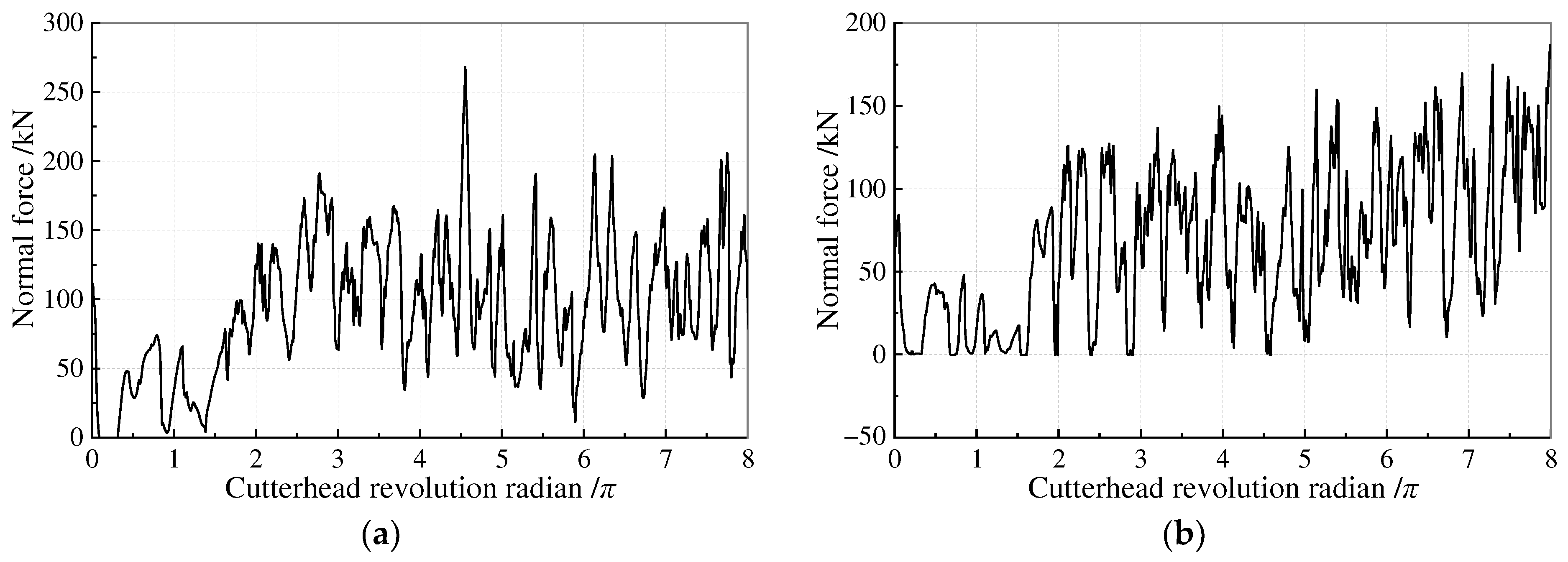
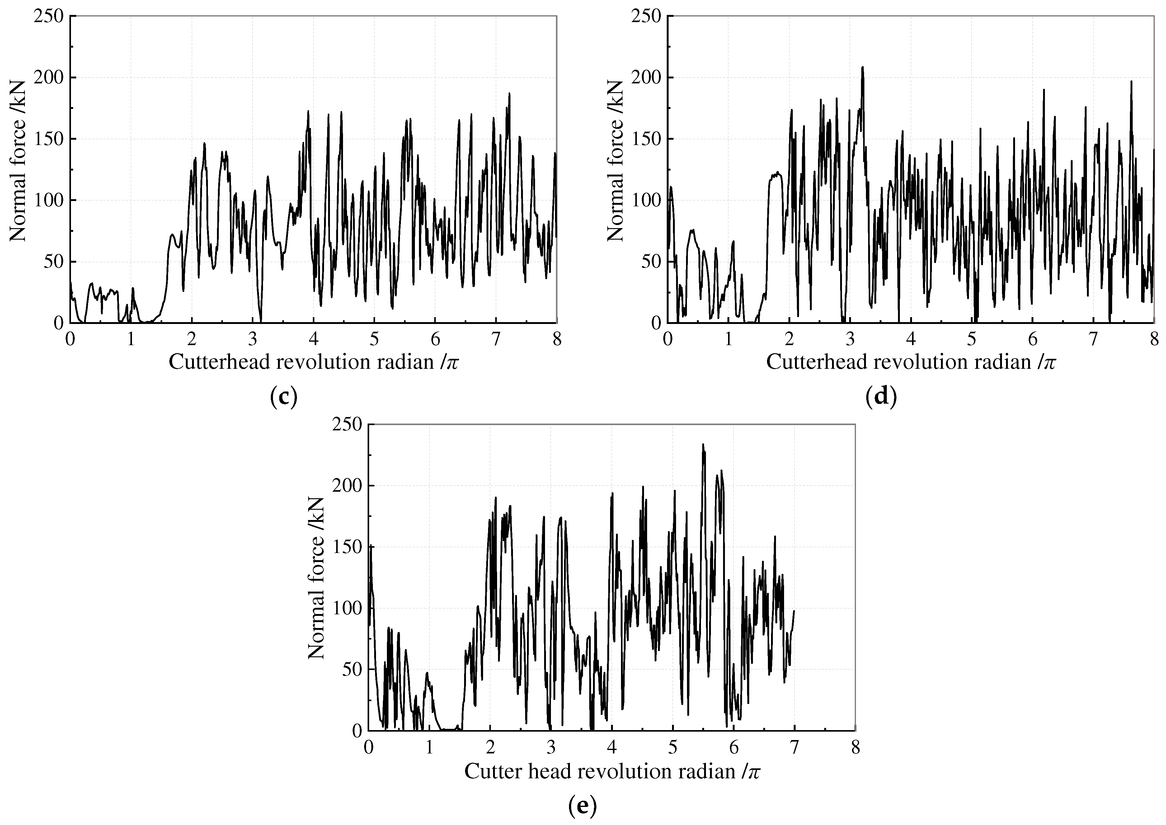
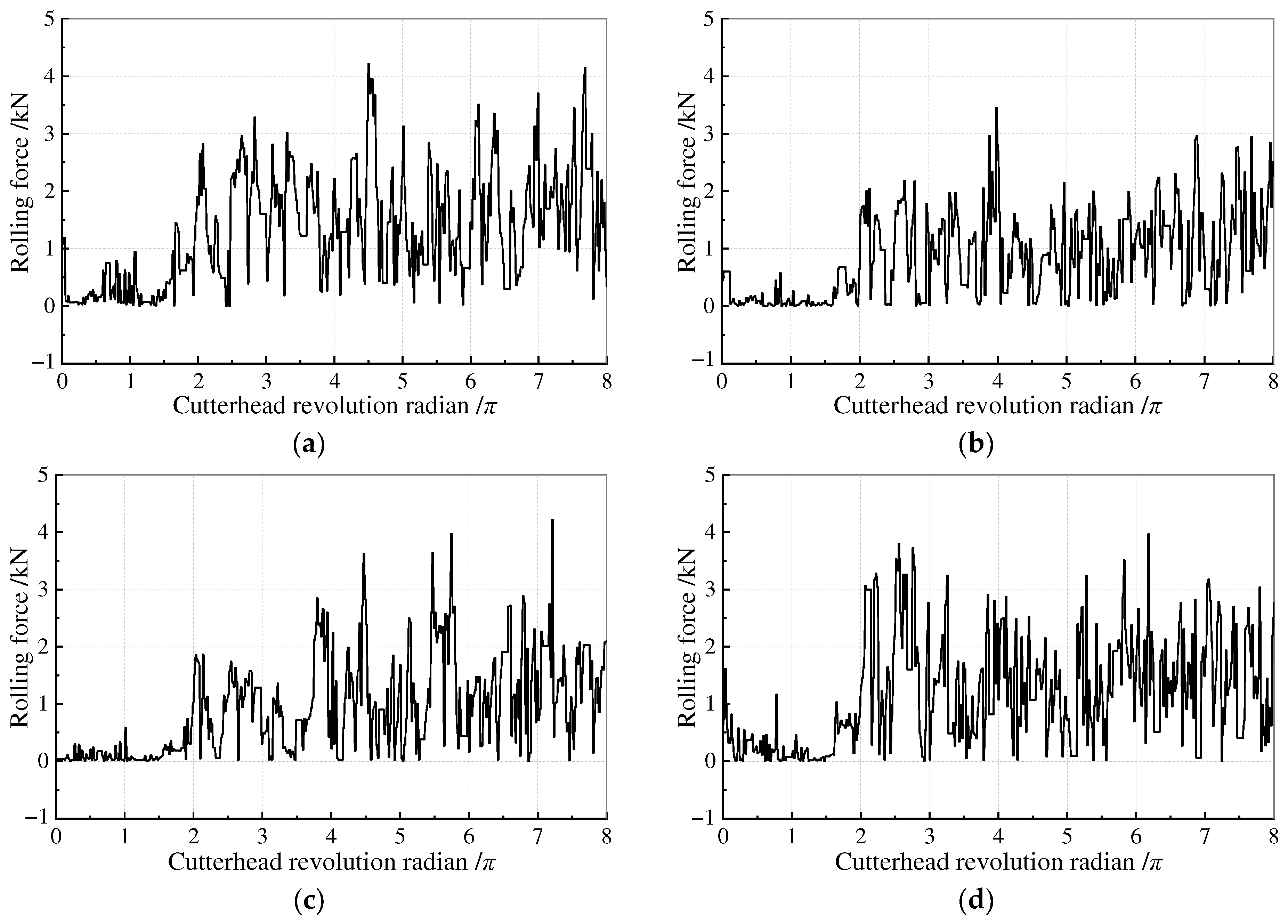
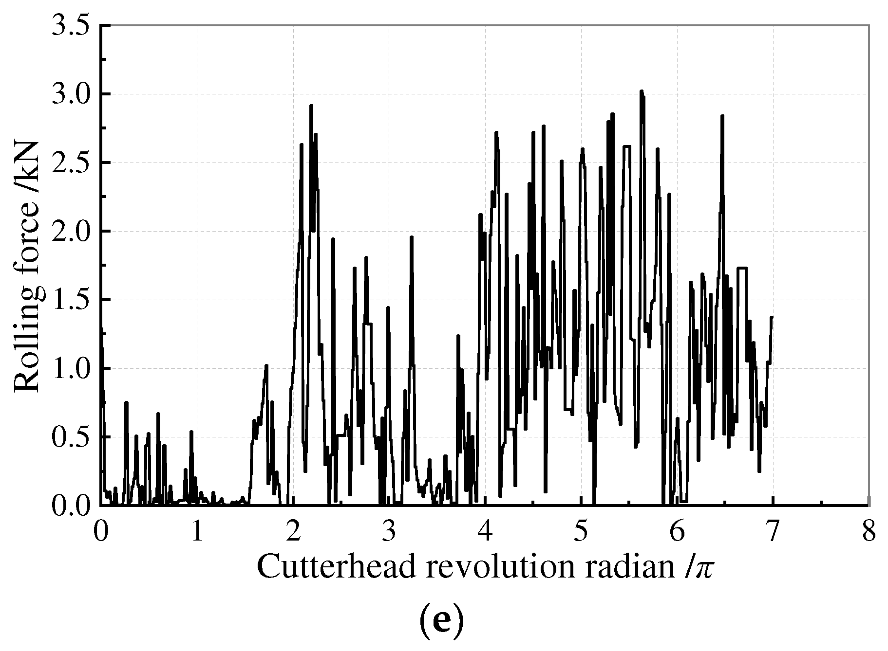
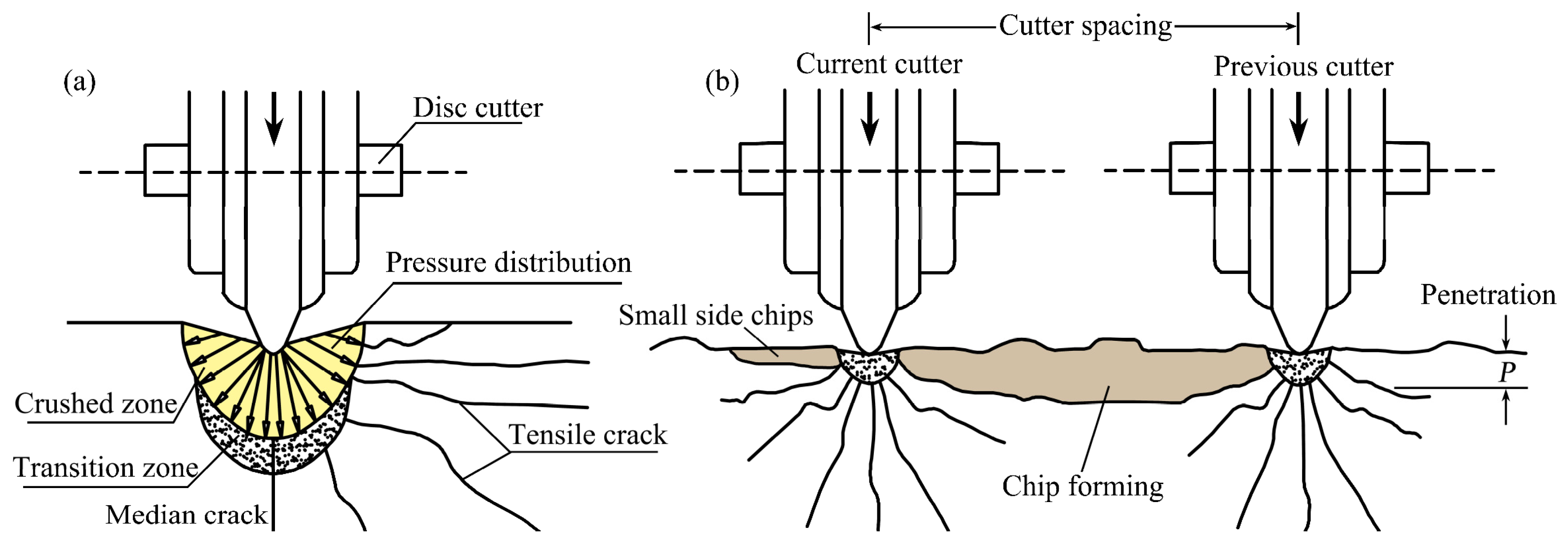
3.2. Rock-Breaking Characteristics of the Cutter

After every test, the rock debris on the rock’s surface was removed, and the depth of the rock pit was measured. The rock pits under different cutter spacings are presented in Figure 4. It can be observed that when the cutter spacing is 70 mm or 90 mm, the rock cracks in the middle area of the adjacent cutters are entirely connected without the formation of rock ridges. When the cutter spacing is 110 mm or 130 mm, the rock cracks in the middle area of the adjacent cutters are not fully connected with the formation of rock ridges. The larger the cutter spacing, the larger the size of the rock ridge.
The cutter’s normal and rolling forces can easily be calculated by the thrust and torque of the cutterhead when only one cutter is installed. The cutter force curves with varying rolling radii are displayed in Figure 5 and Figure 6. The comparison of the cutter force curves for various rolling radii reveals that when the cutterhead rotates within a single circle (0–2π), the rock sample’s flat surface and absence of a stable “rock breaking environment” lead to an unstable fluctuation range of cutter forces. The cutter’s force fluctuation curves steadily stabilize after one circle (>2π).

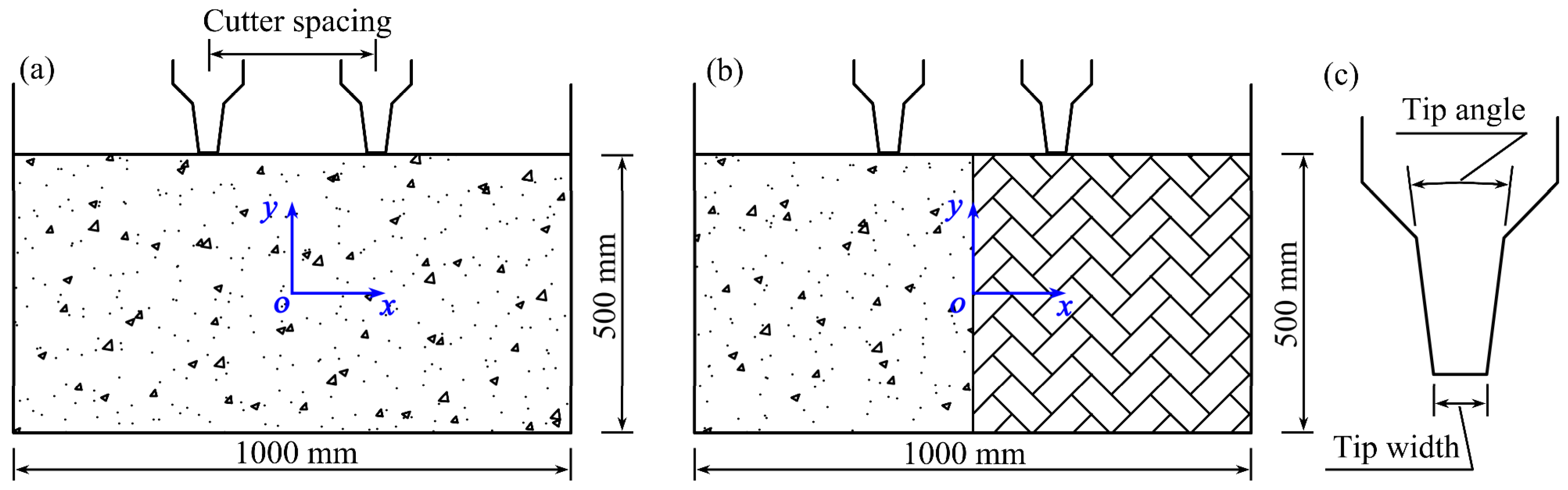
4. Numerical Model of Cutter Breaking Rock

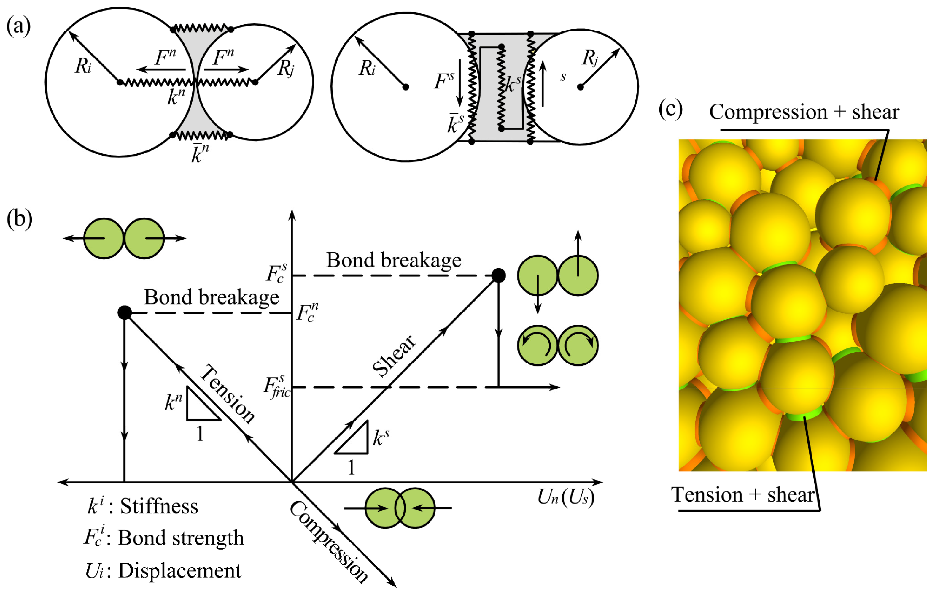
4.1. Particle Flow Model

The particle flow model based on discrete elements is a numerical simulation method based on discontinuous medium mechanics, which can study objects’ mechanical properties and behavior from a micro perspective. The explicit central difference method is used to solve the motion equation of the elements. Because all matrices do not require storage, many particle elements only require moderate computer memory. Accurately describing the nonlinear characteristics of the medium through the changes in the contact state between particles within the medium system ensures rapid convergence and stable solutions in unstable physical processes such as large deformation, fracture, and detachment.
Particle flow combines stacked circular particles (disks or balls) to simulate the research object. During the model generation process, different macroscopic physical and mechanical properties can be simulated by adjusting the properties and arrangement of particles. The contact behavior between particles determines the expression of the model’s macroscopic mechanical properties [25]. Figure 7 illustrates the bonded-particle model (BPM) [26]. The bonded-particle model considers bonding discrete particle elements together, and this bond can fracture under certain strength criteria. The commonly used bond models include the contact and parallel bond models. The parallel bond model was used in this study.
As seen in Figure 8, a disc cutter is primarily made up of a cutter ring, cutter body, shaft, bearing, and end cover. The primary cutting element, the cutting ring, has a direct impact on the effectiveness of rock fragmentation through its performance. The cutter ring applies force to the rock in three different directions during the rock-breaking process: normal force, rolling force, and side force.
The cutter mainly cracks the rock through the normal force, while the side and rolling forces are used primarily to crush and grind the rock. The rock failure process mostly occurs in the plane perpendicular to the traveling direction of the cutter, and the horizontal forces are relatively small compared with normal force [27]. Therefore, the side force and rolling force on the cutter can be ignored, and the effect of the normal force is mainly considered.
While the side and rolling forces are generally employed to crush and grind the rock, the cutter primarily uses normal force to crack the rock. Compared to the normal force, the horizontal forces acting on the rock are minor, and the rock failure process usually occurs in the plane perpendicular to the cutter’s traveling direction [27]. Consequently, the normal force’s impact is primarily considered, and the side force and rolling force on the cutter can be disregarded. The three-dimensional issue of the rock breaking is simplified to a two-dimensional one. Gong et al.’s study [20,28] indicates that it is possible to streamline the cutter’s rock-breaking issue into a two-dimensional planar issue. Cutter rock-breaking models were created based on the investigation above, as established in Figure 9.

4.2. Surrounding Rock Parameters

This study selects four strata with significant strength differences for analysis: strata A, B, C, and D, from high to low strength. The rock mechanical parameters are listed in Table 2. In the modeling process, numerical tests (uniaxial, Brazilian splitting tests, etc.) are generally used to calibrate the mesoscopic parameters of rock materials. Based on the trial-and-error method, the mesoscopic parameters obtained by calibration are listed in Table 3.

4.3. Cutter Parameters

A wedge-shaped cutting tool can obtain a higher cutting rate when the rock mass is less abrasive. However, in a highly abrasive hard rock stratum, especially in soft–hard composite strata, the tip of a wedge-shaped cutting tool will wear rapidly, and the rock-breaking efficiency will be significantly reduced [29,30]. The constant cross-section disc cutter well overcomes the insufficiency of wedge-shaped cutting tools. After wear, it can still maintain an approximately constant cross-section size of the tip without significantly affecting the rock-breaking efficiency. Therefore, studying the rock-breaking process of constant cross-section disc cutters is more instructive for practical engineering. According to the difference in tip width and angle, the cutter ring of a constant cross-section disc cutter is divided into two types: flat tip and wedge tip. Because flat-tip cutters are widely used in engineering, this paper took the flat-tip cutter ring as the research object. Cutter rings have extremely high hardness, stiffness, and strength. Therefore, the cutter ring can be regarded as a rigid body, and the outline of the cutter ring can be simulated with a rigid “wall”. This study selected four types of flat-tip cutters with tip widths of 10 mm, 15 mm, 20 mm, and 30 mm. The cutter ring parameters are listed in Table 4.

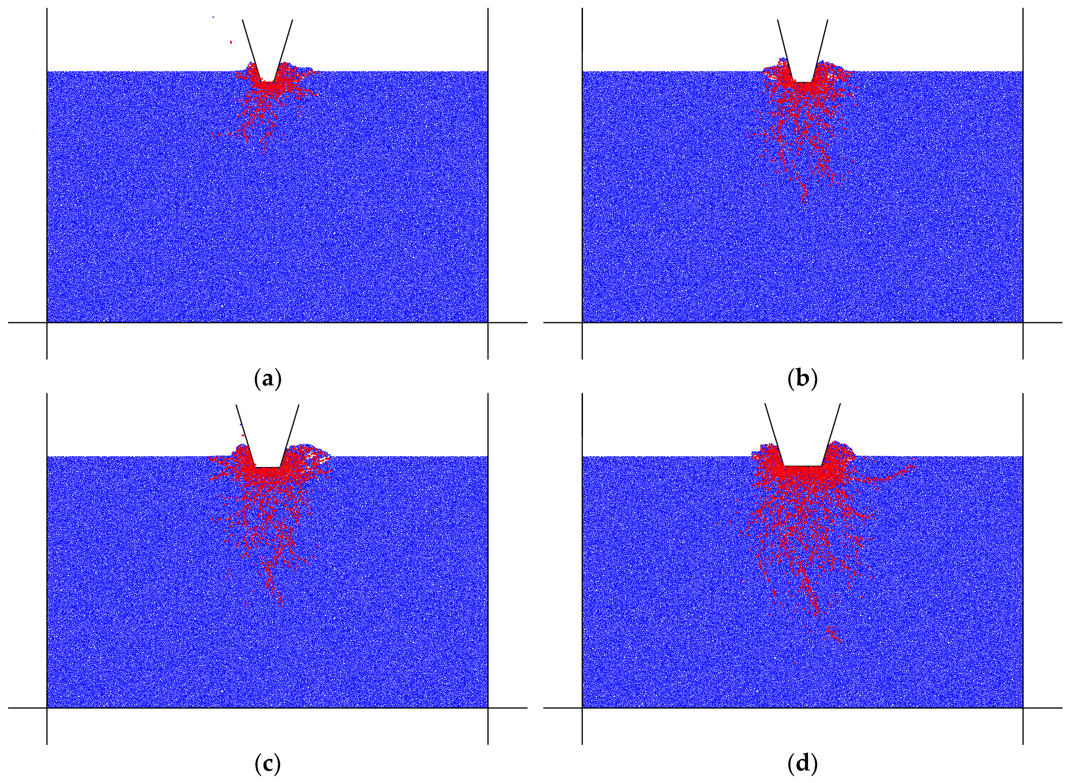
5. Numerical Results

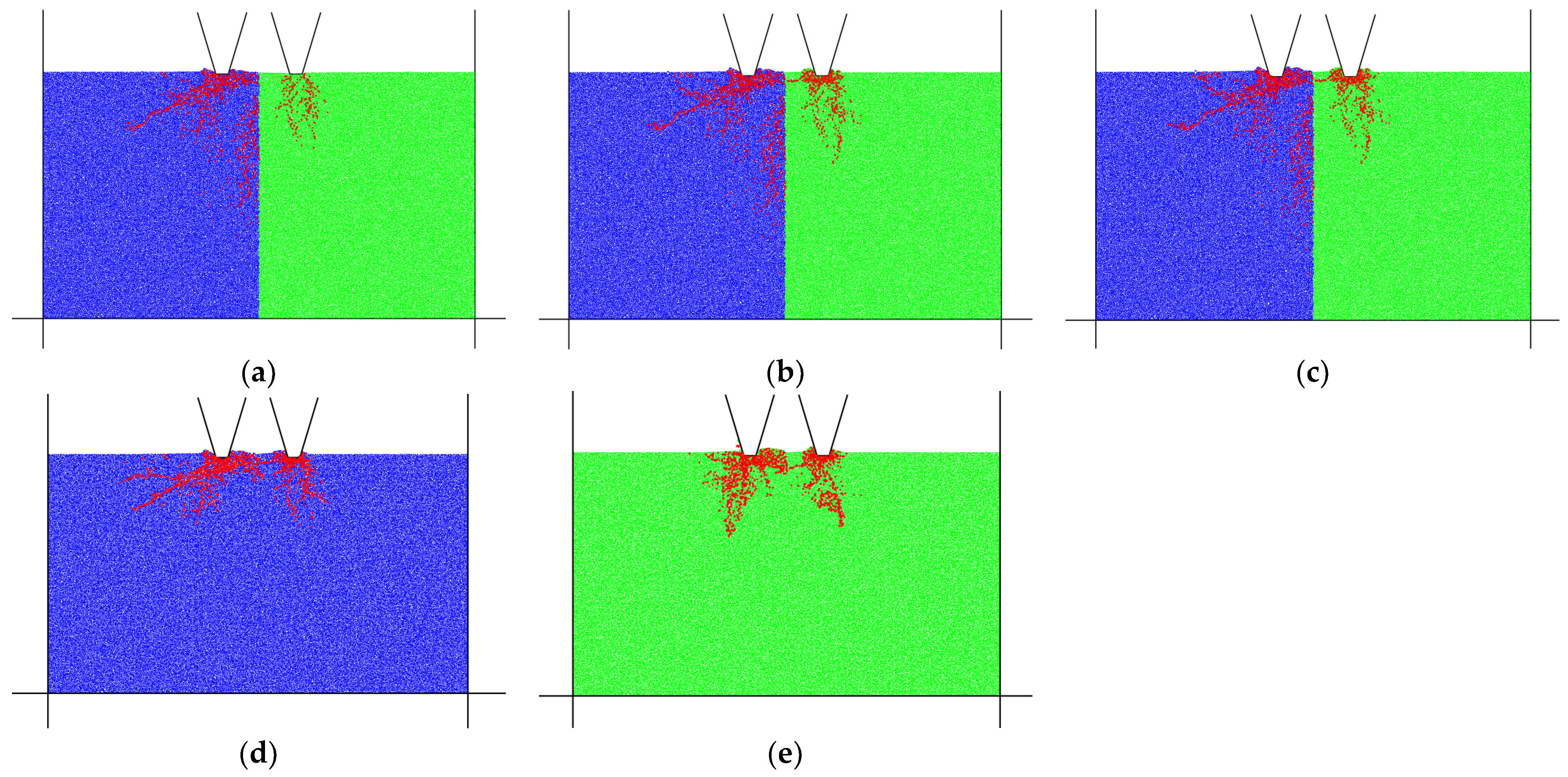
5.1. Rock-Breaking Characteristics of Composite Strata

When TBM passes through composite strata, the cutters on the cutterhead must meet the crushing requirements of both hard and soft rock. Starting from a homogeneous rock stratum, this section simulated a specific penetration of different types of cutters into the rock based on the particle flow method and recorded the number of cracks in the rock to evaluate the rock-breaking performance of various sizes of cutters. A reasonable cutter size was obtained under different rock conditions, and then the rock-breaking characteristics of the cutter in composite strata were analyzed. The size selection of the cutter in engineering should be based on the number, width, and depth of cracks broken by the cutter under the selected penetration and the cutter force. According to the present research, under a specific penetration, the larger the tip width, the more cracks the cutter produces, and the better the rock-breaking effect, but at the same time, the greater the force on the cutter, the faster the wear. Stratum B is taken as an example for verification.
The penetration in the numerical simulation was set to 10 mm. Figure 10 shows the distribution of rock cracks obtained from the numerical simulation of rock breaking with four types of flat-tip cutters. Figure 11 shows the curve of the crack number and the force on the cutter with the tip widths. The figures show that in the homogeneous stratum B, the number of cracks and the force on the cutter increase with the tip width, which also verifies the above conclusion.
The cutter selection should also consider the force difference between two adjacent cutters in soft–hard composite strata. The smaller the force difference, the more conducive it is to the overall stability of the cutterhead. Figure 12 shows the variation curve of cutter force with tip width in homogeneous strata A, B, C, and D. It can be seen from the figure that for a specific rock, the cutter force increases with the increase in cutter tip width; for a particular width of the tip, the cutter force also increases with the rise in rock strength.
When a TBM is tunneling in soft–hard composite strata, adjacent cutters on the cutterhead will simultaneously contact rocks with different strengths at the interface between soft rock and hard rock. For example, in A and C composite strata, if the optimal tip width (15 mm) corresponding to a single cutter when breaking the homogeneous stratum C is selected, the maximum force on the cutter is 186.3 kN when the cutter breaks composite strata, which is close to the rated cutter normal force (215 kN) and unfavorable to the cutter. Suppose the optimal tip width (10 mm) corresponding to a single cutter is selected when breaking homogeneous stratum A. In that case, the maximum force on the cutter is 159.2 kN when the cutter breaks composite strata, which is lower than the rated cutter’s normal force and satisfies the cutter force requirements. At the same time, no matter whether a cutter with a tip width of 10 mm or 15 mm is selected, the maximum force on the cutter appears in stratum A, and the maximum value is less than that of a single cutter breaking homogeneous stratum A.
Consistent conclusions can be obtained by analyzing other soft–hard composite strata composite conditions. Therefore, under the condition of soft–hard composite strata, the cutter selection should prioritize the cutter force, and the maximum contact force of the cutter breaking rock appears in the hard rock stratum. It is safe enough to select the optimal size for the cutter breaking rock in the harder stratum in composite strata.

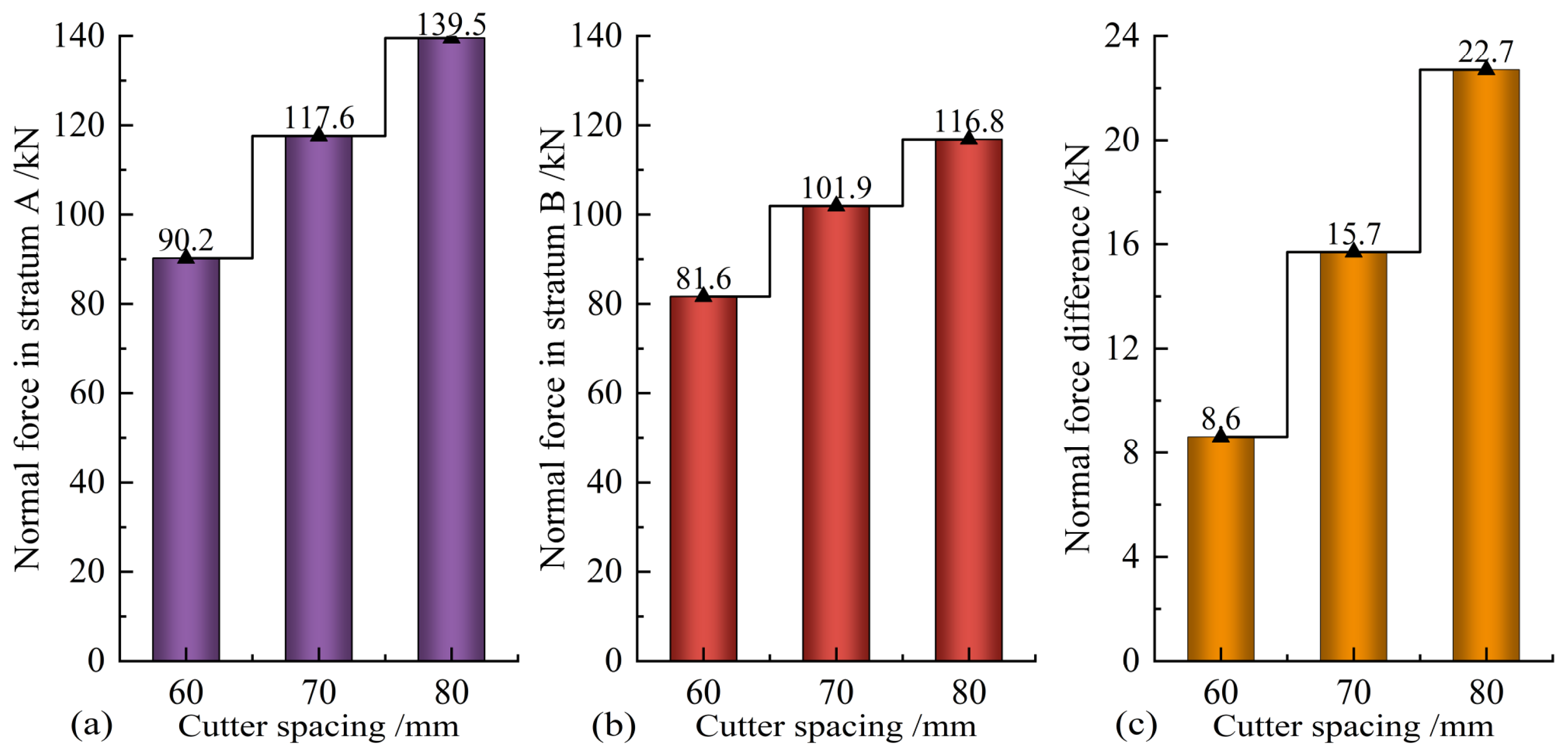
5.2. Matching of Cutter Spacing and Penetration in Composite Strata

Under the condition that the cutter size has been selected, the matching degree of cutter spacing and penetration directly affects the rock-breaking effect. There is an optimal value for penetration when the cutter spacing is determined. When the cutter spacing has been determined, if the penetration is too large, the transverse cracks generated by the two adjacent cutters penetrating the rock will not penetrate, and the rock-breaking requirements will not be met. If the penetration is too small, many transverse cracks will be generated between the cutters, and a large amount of rock slag will be formed between the cutters, which wastes the rock-breaking energy and reduces the rock-breaking efficiency. The ideal rock-breaking effect of the cutter is to match the optimal penetration. Just a few transverse cracks are penetrating between two cutters, forming a convex lenticular rock chip, as presented in Figure 13, which is the most efficient strategy for breaking the rock.
For TBM construction in composite strata, the selection of cutter spacing is the key to the design of the TBM cutterhead. When a TBM has been manufactured and put into service, it is difficult to modify the cutterhead to adjust the cutter spacing. Therefore, during construction, the penetration is often adjusted by changing the thrust of the TBM. Finally, the most efficient rock-breaking method is realized so the TBM can adapt to different geological conditions. This section selected the typical A and B composite strata for numerical simulation analysis to study the matching optimization of cutter spacing and penetration in composite strata. According to the analysis in Section 5.1, the optimal cutter tip width in the harder rock stratum should be selected, that is, 10 mm cutter tip width in stratum A. According to engineering experience, in stratum A, the cutter spacing is about 70 mm. Therefore, three knife distances of 60 mm, 70 mm, and 80 mm are selected for numerical simulation calculation. Two cutters penetrate the rock simultaneously, and the penetration value is 0–10 mm. The optimal penetration is chosen by observing the transverse crack extension of rock between two cutters.
Numerical simulation results of cutters breaking rock with 60 mm cutter spacing are shown in Figure 14. It can be seen from Figure 14a that when the penetration is 2 mm, the transverse cracks generated between the cutters do not penetrate, so convex lens-shaped rock chips cannot be formed and peeled off from the parent rock. Therefore, the penetration cannot meet the rock-breaking requirements, indicating that the penetration is too small in this case. It can be seen from Figure 14c that when the penetration is 4 mm, a crushing area is formed between the two cutters, and this crushing zone mainly occurs in the stratum B area (left half of the model). This is because the strength of stratum B is less than that of stratum A. Under the same penetration, stratum B produces more cracks, so stratum B first produces a crushing zone. In this case, most of the rock-breaking energy of the cutter is used to create fine cracks. Although it can meet rock-breaking requirements, compared with the rock-breaking effect when the penetration is 3 mm, the energy waste is large, and the rock-breaking efficiency is low. Therefore, the penetration is set too large in this case. It can be seen from Figure 14b that when the penetration is 3 mm, the rock between the cutters forms a transverse crack, forming a convex lens-shaped rock chip. Under the disturbance caused by the rotation of the cutterhead, the rock chips will fall from the tunnel face. It can be seen from Figure 14 that the distribution of cracks between the two cutters is not uniform, and stratum B on the left produces more micro-cracks near the cutter. This is the inevitable result of two cutters penetrating different rocks. Using the “measured circle” function of the particle flow code, it can be obtained that the maximum forces on the two cutters are 90.2 kN and 81.6 kN, respectively. The force difference of the cutters is 8.6 kN.
When a TBM is tunneling in soft–hard composite strata, the cutters not only work at the stratum interface, but more often, they break a homogeneous rock stratum. The rock-breaking effect of homogeneous strata A and B when the penetration is 3 mm and the cutter spacing is 60 mm is verified, as shown in Figure 14d,e. The results show that when the penetration is 3 mm and the cutter spacing is 60 mm, for stratum A, a transverse crack is formed between the two cutters, and a convex lens-shaped rock chip is formed between the cutters. For stratum B, cracks and a small crushing zone are also formed between the two cutters. This is because the strength of stratum B is lower than that of stratum A. When stratum B is penetrated with the same cutter parameters and penetration as stratum A, more ineffective cracks are formed. In this case, a certain waste of energy will be caused, but the requirements of rock breaking will also be met. According to the above analysis, for the A and B composite strata, when the cutter spacing is 60 mm, the optimal penetration is 3 mm.
The same analysis shows that when the cutter spacing is 70 mm, the optimal penetration is 4 mm; when the cutter spacing is 80 mm, the optimal penetration is 6 mm. The variation curve of cutter force with cutter spacing in A and B composite strata is shown in Figure 15. Through comparison, it can be seen that when the cutter spacing is 60 mm, the force and force difference of cutters are the smallest. This is because the penetration of the cutter is 3 mm in this case, which is the minimum value among the three cases. The smaller the penetration, the smaller the force on the cutter; the smaller the cutter spacing, the greater the possibility of a crack connection between the two cutters, the easier the rock is to break, and the smaller the force difference is. For the A and B composite strata, the most reasonable setting of cutter spacing is 60 mm, and the optimal penetration of matching is 3 mm.

6. Conclusions

Rock-breaking characteristics of TBM cutters and matching cutter spacing and penetration are the key research issues in TBM tunnel construction in composite strata. The main conclusions of this study are as follows:
(1)
The normal force of the cutter is comprehensively affected by the rolling radius and cutter spacing. The rolling force of the cutter is less affected by the cutter spacing when the cutter breaks rock.
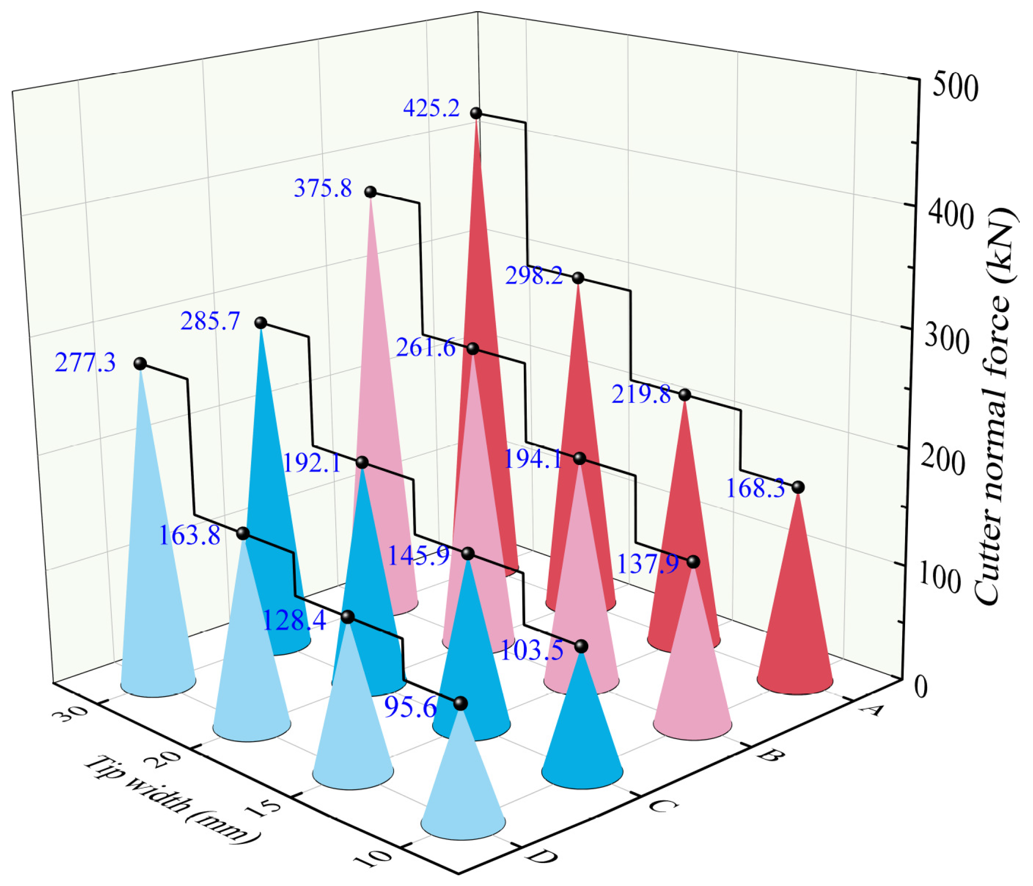
(2)
For a homogeneous rock stratum, under a specific penetration, the larger the tip width, the more cracks generated by the cutter, and the better the rock-breaking effect, but at the same time, the greater the force on the cutter.
(3)
For soft–hard composite strata, the cutter selection should prioritize the cutter force, and the maximum force of cutter breaking rock appears in the hard rock stratum. It is safe enough to select the optimal cutter size in the harder stratum.
(4)
The force of cutter breaking rock in composite strata increases with the increase in penetration, and the force difference of cutters decreases with the decrease in cutter spacing.
The interaction between TMB cutters and rocks is a complex systematic issue, and further explorations and investigations are as follows: (1) load and vibration characteristics of TBM cutterhead and cutters with different cutter profiles; (2) detection, evaluation, and prediction of cutter wear; (3) prediction of TBM tunneling parameters using a machine learning method; and (4) knowledge-based and data-based machine learning in intelligent TBM construction.

Author Contributions

Conceptualization, H.Z.; data curation, M.X.; formal analysis, H.Z.; funding acquisition, Z.Z.; investigation, M.X.; methodology, H.Z.; project administration, Z.Z.; resources, Z.Z.; software, H.Z., M.X., and F.H.; supervision, Z.Z.; validation, M.X. and F.H.; writing—original draft, H.Z. and F.H.; writing—review and editing, M.X. All authors have read and agreed to the published version of the manuscript.

Funding

This research was funded by the Science and Technology Program of Nanchang Rail Transit Group Limited Corporation of China, grant number 2019HGKYB003.

Data Availability Statement

The data used to support the findings of this study are available from the corresponding author upon request.

Conflicts of Interest

Authors Huipeng Zhang, Ming Xia and Fengyuan Huang were employed by the Nanchang Rail Transit Group Limited Corporation. The remaining author declares that the research was conducted in the absence of any commercial or financial relationships that could be construed as a potential conflict of interest.

References

  1. Liu, C.; Cui, J.; Zhang, Z.; Liu, H.; Huang, X.; Zhang, C. The role of TBM asymmetric tail-grouting on surface settlement in coarse-grained soils of urban area: Field tests and FEA modelling. Tunn. Undergr. Space Technol. 2021, 111, 103857. [Google Scholar] [CrossRef]
  2. He, H.; Wang, S.; Shen, W.; Zhang, W. The influence of pipe-jacking tunneling on deformation of existing tunnels in soft soils and the effectiveness of protection measures. Transp. Geotech. 2023, 42, 101061. [Google Scholar] [CrossRef]
  3. Zhang, Z.; Zhang, K.; Dong, W.; Zhang, B. Study of rock-cutting process by disc cutters in mixed ground based on three-dimensional particle flow model. Rock Mech. Rock Eng. 2020, 53, 3485–3506. [Google Scholar] [CrossRef]
  4. Zhao, Y.; Yang, H.; Chen, Z.; Chen, X.; Huang, L.; Liu, S. Effects of jointed rock mass and mixed ground conditions on the cutting efficiency and cutter wear of tunnel boring machine. Rock Mech. Rock Eng. 2019, 52, 1303–1313. [Google Scholar] [CrossRef]
  5. Fu, K.; Qiu, D.; Xue, Y.; Shao, T.; Lan, G. TBM tunneling strata automatic identification and working conditions decision support. Autom. Constr. 2024, 163, 105425. [Google Scholar] [CrossRef]
  6. Mousapour, H.; Chakeri, H.; Darbor, M.; Hekmatnejad, A. Evaluating the wear of cutting tools using a tunnel boring machine laboratory simulator. Min. Miner. Depos. 2023, 17, 28–34. [Google Scholar] [CrossRef]
  7. Barzegari, G.; Khodayari, J.; Rostami, J. Evaluation of TBM cutter wear in Naghadeh water conveyance tunnel and developing a new prediction model. Rock Mech. Rock Eng. 2021, 54, 6281–6297. [Google Scholar] [CrossRef]
  8. Ren, D.J.; Shen, S.L.; Zhou, A.; Chai, J.C. Prediction of lateral continuous wear of cutter ring in soft ground with quartz sand. Comput. Geotech. 2018, 103, 86–92. [Google Scholar] [CrossRef]
  9. Liu, Q.; Liu, J.; Pan, Y.; Kong, X.; Cui, X.; Huang, S.; Wei, L. Research advances of tunnel boring machine performance prediction models for hard rock. Chin. J. Rock Mech. Eng. 2016, 35, 2766–2786. (In Chinese) [Google Scholar]
  10. Geng, Q.; Wei, Z.; Meng, H. An experimental research on the rock cutting process of the gage cutters for rock tunnel boring machine (TBM). Tunn. Undergr. Space Technol. 2016, 52, 182–191. [Google Scholar]
  11. Pan, Y.; Liu, Q.; Peng, X.; Kong, X.; Liu, J.; Zhang, X. Full-scale rotary cutting test to study the influence of disc cutter installment radius on rock cutting forces. Rock Mech. Rock Eng. 2018, 51, 2223–2236. [Google Scholar] [CrossRef]
  12. Zhang, K.; Yang, H.; Zhang, Z. Experimental and numerical investigations on the force characteristics of cutter in different regions of the TBM cutterhead. Tunn. Undergr. Space Technol. 2024, 149, 105800. [Google Scholar] [CrossRef]
  13. Gertsch, R.; Gertsch, L.; Rostami, J. Disc cutting tests in Colorado Red Granite: Implications for TBM performance prediction. Int. J. Rock Mech. Min. Sci. 2007, 44, 238–246. [Google Scholar] [CrossRef]
  14. Peng, X.; Liu, Q.; Pan, Y.; Lei, G.; Wei, L.; Luo, C. Study on the influence of different control modes on TBM disc cutter performance by rotary cutting tests. Rock Mech. Rock Eng. 2018, 51, 961–967. [Google Scholar] [CrossRef]
  15. Gong, Q.M.; Dong, G.L.; Yin, L.J.; Ma, S.; Lu, J.W. Comparison study on the rock linear and rotating cutting test by TBM cutter. Constr. Technol. 2017, 46, 61–66. (In Chinese) [Google Scholar]
  16. Cho, J.W.; Jeon, S.; Jeong, H.Y.; Chang, S.H. Evaluation of cutting efficiency during TBM disc cutter excavation within a Korean granitic rock using linear-cutting-machine testing and photogrammetric measurement. Tunn. Undergr. Space Technol. 2013, 35, 37–54. [Google Scholar] [CrossRef]
  17. Balci, C. Correlation of rock cutting tests with field performance of a TBM in a highly fractured rock formation: A case study in Kozyatagi-Kadikoy metro tunnel. Tunn. Undergr. Space Technol. 2009, 24, 423–435. [Google Scholar] [CrossRef]
  18. Entacher, M.; Schuller, E.; Galler, R. Rock failure and crack propagation beneath disc cutters. Rock Mech. Rock Eng. 2015, 48, 1559–1572. [Google Scholar] [CrossRef]
  19. Xia, Y.M.; Guo, B.; Cong, G.Q.; Zhang, X.H.; Zeng, G.Y. Numerical simulation of rock fragmentation induced by a single TBM disc cutter close to a side free surface. Int. J. Rock Mech. Min. Sci. 2017, 91, 40–48. [Google Scholar] [CrossRef]
  20. Gong, Q.M.; Zhao, J.; Hefny, A.M. Numerical simulation of rock fragmentation process induced by two TBM cutters and cutter spacing optimization. Tunn. Undergr. Space Technol. 2006, 21, 263–270. [Google Scholar] [CrossRef]
  21. Gong, Q.M.; Zhao, J.; Jiao, Y.Y. Numerical modeling of the effects of joint orientation on rock fragmentation by TBM cutters. Tunn. Undergr. Space Technol. 2005, 20, 183–191. [Google Scholar] [CrossRef]
  22. Zhang, X.H.; Xia, Y.M.; Liu, J.; Tan, Q. Study on characteristics of breaking rock by double edge central disc cutter under confining pressure. J. Northeast. Univ. Nat. Sci. 2017, 38, 839–844. (In Chinese) [Google Scholar]
  23. Wen, S.; Zhang, C. Experimental and simulation study on rock-breaking efficiency of disc cutters on composite rocks. Int. J. Rock Mech. Min. Sci. 2022, 153, 105089. [Google Scholar] [CrossRef]
  24. Cho, J.W.; Jeon, S.; Yu, S.H.; Chang, S.H. Optimum spacing of TBM disc cutters: A numerical simulation using the three-dimensional dynamic fracturing method. Tunn. Undergr. Space Technol. 2010, 25, 230–244. [Google Scholar] [CrossRef]
  25. Zhang, K.; Liu, Z.; Zhang, Z. A case study of cutting performance by a transverse cutting head based on three-dimensional particle flow model. KSCE J. Civ. Eng. 2023, 27, 2248–2262. [Google Scholar] [CrossRef]
  26. Potyondy, D.O.; Cundall, P.A. A bonded-particle model for rock. Int. J. Rock Mech. Min. Sci. 2004, 41, 1329–1364. [Google Scholar] [CrossRef]
  27. Xu, Z.M.; Huang, R.Q.; Zhang, Z.Y. The mechanical parameters of surrounding rocks considered in TBM cutter design. Chin. J. Rock Mech. Eng. 2001, 2, 230–234. (In Chinese) [Google Scholar]
  28. Gong, Q.M.; Jiao, Y.Y.; Zhao, J. Numerical modeling of the effects of joint spacing on rock fragmentation by TBM cutters. Tunn. Undergr. Space Technol. 2006, 21, 46–55. [Google Scholar] [CrossRef]
  29. Wijk, G. A model of tunnel boring machine performance. Geotech. Geol. Eng. 1992, 10, 19–40. [Google Scholar] [CrossRef]
  30. Sanio, H.P. Prediction of the performance of disc cutters in anisotropic rock. Int. J. Rock Mech. Min. Sci. 1985, 22, 153–161. [Google Scholar] [CrossRef]
Figure 1. Full-scale rotary cutting machine.
Buildings 14 01757 g001
Figure 2. Preparation of rock samples.
Buildings 14 01757 g002
Figure 3. Rock-breaking process of a cutter under different rotation radii. (a) R = 0.450 m; (b) R = 0.525 m; (c) R = 0.615 m; (d) R = 0.725 m; (e) R = 0.855 m.
Buildings 14 01757 g003
Figure 4. Rock pits under different cutter spacings. (a) Cutter spacing 75 mm; (b) cutter spacing 90 mm; (c) cutter spacing 110 mm; (d) cutter spacing 130 mm.
Buildings 14 01757 g004
Figure 5. Normal forces of the cutter with different rock-breaking radii. (a) R = 0.450 m; (b) R = 0.525 m; (c) R = 0.615 m; (d) R = 0.725 m; (e) R = 0.855 m.
Buildings 14 01757 g005aBuildings 14 01757 g005b
Figure 6. Rolling forces of the cutter with different rock-breaking radii. (a) R = 0.450 m; (b) R = 0.525 m; (c) R = 0.615 m; (d) R = 0.725 m; (e) R = 0.855 m.
Buildings 14 01757 g006aBuildings 14 01757 g006b
Figure 7. Bond model of particles. (a) Contact stiffness between particles; (b) parallel bond constitutive relation; (c) bond between particles.
Buildings 14 01757 g007
Figure 8. Force diagram of disc cutter. (a) Main components of disc cutter; (b) force of disc cutter.
Buildings 14 01757 g008
Figure 9. Rock-breaking model with double cutters. (a) Homogeneous stratum; (b) composite strata; (c) parameters of cutter ring.
Buildings 14 01757 g009
Figure 10. Crack distribution of rock breaking in homogeneous stratum B: (a) 10 mm tip width; (b) 15 mm tip width; (c) 20 mm tip width; (d) 30 mm tip width.
Buildings 14 01757 g010
Figure 11. Variation curve of crack number and cutter force with tip width in homogeneous stratum B.
Buildings 14 01757 g011
Figure 12. Variation curve of cutter force with tip width in homogeneous rock stratum.
Buildings 14 01757 g012
Figure 13. Rock crack propagation. (a) Rock fragmentation by single disc cutter; (b) rock fragmentation by two disc cutters.
Buildings 14 01757 g013
Figure 14. Numerical results with 60 mm cutter spacing. The blue area represents stratum A, while the green area represents stratum B. (a) A and B composite strata, 2 mm penetration; (b) A and B composite strata, 3 mm penetration; (c) A and B composite strata, 4 mm penetration; (d) homogeneous stratum A, 3 mm penetration; (e) homogeneous stratum B, 3 mm penetration.
Buildings 14 01757 g014
Figure 15. Cutter normal force in A and B composite strata. (a) Normal force of cutter in stratum A; (b) normal force of cutter in stratum B; (c) normal force difference between two cutters.
Buildings 14 01757 g015
Table 1. Main technical parameters of RCM.
NameMain ParameterSupplementary Remarks
Axial loading deviceMaximum advance load/t100
Maximum number of cutters317-inch and 19-inch disc cutters
Advance speed/(mm·min−1)0.05–50
Axial load control strategyClosed-loop servoForce control and displacement control
Axial force control accuracy/N20±1%
Actuator stroke/mm900
Cutter spacing/mm60–180Adjustable cutter spacing
Rotation deviceInner ring diameter/m0.5
Outer ring diameter/m2
Rock sample thickness /cm30–50
Rotation speed/(r·min−1)0–2
Maximum rotational torque/(kN·m)±10
Table 2. Mechanical parameters of different strata.
Stratum TypeUniaxial Compressive Strength/MPaInternal Friction Angle/°Cohesion/
MPa
Elastic Modulus/
GPa
Poisson’s Ratio
A1206513.8450.21
B805512.6320.25
C59.648.811.2180.26
D30.540.17.1100.27
Table 3. Mesoscopic parameters of the particle flow model.
Stratum TypeEffective Modulus/GPaNormal-to-Shear Stiffness RatioBond Effective Modulus/GPaBond Normal-to-Shear Stiffness RatioTensile Strength/MPaCohesion/MPaFriction Angle/°Friction Coefficient
A203.010.53.02618.5250.20
B123.06.23.0178.6270.25
C73.01.83.085.2300.28
D0.53.00.23.021.5350.30
Table 4. Cutter ring parameters.
Types of Cutter RingTip Angle/°Tip Width/mm
#135°10
#235°15
#335°20
#435°30
Disclaimer/Publisher’s Note: The statements, opinions and data contained in all publications are solely those of the individual author(s) and contributor(s) and not of MDPI and/or the editor(s). MDPI and/or the editor(s) disclaim responsibility for any injury to people or property resulting from any ideas, methods, instructions or products referred to in the content.

