1. Introduction
As a kind of beam bridge structure widely used in practical engineering, U-beam bridges have the advantages of lower structure height and excellent anti-noise performance compared with box-beam bridges because of their unique structural characteristics [
1,
2]. U-beam bridges have become one of the important forms of railway and urban rail bridges. As urban rail transit bridges are constantly built in complex urban environments, there are high requirements for road clearance and noise control, and U-shaped bridges can significantly reduce the structural height and excel in noise control, making them highly suitable for the design and construction of urban rail transit [
3].
Precast segmental techniques can reduce the influence of adverse factors such as weather conditions. Precast segmental techniques have the additional benefit of mitigating the long-term effects typically associated with concrete girder bridges [
4,
5]. They improve construction efficiency, shorten project durations, and reduce construction costs [
6]. To date, precast segmental techniques have been widely used in the construction of traffic bridges, such as the Bang Na Expressway [
7], Erqi Yangtze River Bridge [
8], and so on. To ensure sufficient strength, stiffness, and stability under dead and live loads, segmental bridges typically adopt various joint types, including dry joints, wet joints, and epoxy joints. Dry joints rely on the structural design and steel components of the segments for connection without any adhesives. Wet joints involve filling concrete between different segments to connect them. Epoxy joints use epoxy resin as the binder at segmental joints, providing better shear resistance compared to dry joints [
9]. Epoxy joints can also cause the specimen to break at the web or support, resulting in the same failure form as the whole cast-in-place specimen so that the bridges can has a higher strength. In cases of dry joints, the specimen typically experiences slippage or shear bond failure at the joints [
10,
11,
12,
13,
14,
15].
For segmental bridges with different load-carrying forms and structures, factors such as the thickness of adhesives and the shape and distribution of keys greatly influence the joint strength, overall stability, and service behavior of the bridges. Numerous research groups have conducted studies on the mechanical behavior of epoxy joints. For instance, Liang et al. [
16] explored the shear behavior and capacity of multi-keyed epoxy joints in segmental bridges, finding that at high confining pressure levels, the impact of increasing the number of shear keys on the shear capacity of ultra-high-performance concrete epoxy joints diminishes, leading to little additional joint capacity increase. Ye et al. [
17] conducted push-off tests on 11 ultra-high-performance concrete joints to acquire data on failure modes, which showed that the shear capacity of ultra-high-performance concrete joints exhibited an almost linear increase with rising confining stress. Pan et al. [
18] conducted direct shear tests on 18 ultra-high-performance concrete joint specimens. They investigated the impact of factors such as the number of shear keys, confining stress, depth of shear keys, steel fiber volume content in ultra-high-performance concrete, and joint type. In the direct shear test of the ultra-high-performance concrete multi-keyed joint, two distinct shear failure modes were observed, namely synchronous and stepwise shear failure. The unsynchronized damage of ultra-high-performance concrete keys resulted in smaller shear resistance but better ductility in joints experiencing stepwise shear failure. Conversely, specimens exhibiting synchronous straight shear failure demonstrated higher shear resistance but with a brittle failure mode. However, due to the considerable expenses associated with experimental procedures, numerical analysis methods have become increasingly prevalent in recent years.
To further enhance comprehension of the mechanical behavior of precast segmental bridges featuring epoxy joints, there are also numerous researchers who have extensively explored these aspects through numerical simulations. Due to the uncertain mechanical properties of the epoxy adhesive layer, numerical simulation methods for epoxy joints exhibit notable diversity. There are several common numerical simulation methods outlined below. Jang et al. [
19] used the “cohesive behavior model” in ABAQUS 6.14 to model the nonlinear interfacial behavior of epoxy joints. Gopal et al. [
20] utilized a friction model to approximate the shear bonding behavior of epoxy joints. Zhang et al. [
21] employed tie constraints to simulate the keyed part and a friction model for the flat part of the joints. However, some researchers argue against disregarding the impact of adhesive layer thickness on the shear behavior of joints. In finite element analysis modeling, epoxy joints have been represented as a linear elastic material to simulate the thickness of epoxy joints [
22,
23,
24]. Although there are many numerical simulation methods, it is necessary to conduct further research in order to accurately simulate the mechanical behavior of epoxy joints.
In addition, compared to traditional box-girder and T-beam bridges, the structure of U-beam bridges is more unique, making the mechanical behavior of U-beam bridges more complex. Liu et al. [
25] conducted a flexural behavior test on a full-scale model of prestressed ultra-high-performance fiber-reinforced concrete U-beam bridges with unique designs. The results showed that U-beam bridges exhibited symmetrical and coordinated deformation in the central rib, with larger deformation observed on the low-web side compared to the high-web side. Transverse deformation at the bottom of the component was more uniformly distributed than longitudinal deformation. Cracks distributed triangularly around the point of action on the bottom surface of the U-beam, indicating a two-way plate-failure mechanism. The most significant crack formation was observed at the central rib. In summary, many scholars have conducted research on the mechanical behavior of epoxy joints and U-beam bridges. However, due to the coupled effects of factors such as key position, key geometry, and key distribution, there is currently a lack of systematic analysis. There is still insufficient research on joint shear capacity optimization regarding keys in epoxy joints. Therefore, further analysis of the mechanical behavior and joint shear capacity optimization of segmental U-beam bridges is necessary.
This paper mainly analyzes the mechanical behavior and joint shear capacity optimization of segmental U-shaped bridges. This research highlights the significant role of keys in minimizing deformation and improving shear capacity, emphasizing the crucial influence of shear key design on the mechanical behavior of segmental bridges. Through analysis of shear capacity under various conditions, this study offers recommendations regarding key distribution and dimensions that optimize joint shear capacities. Specifically, it suggests that increasing key size within the web plate section notably enhances the mechanical resilience of the bridge.
The structure of this paper is outlined as follows. First, in
Section 2, the research background is introduced. Then, in
Section 3, details of the modeling and calculation based on commercial finite element software ABAQUS 6.14 are presented. Next, in
Section 4, the mechanical behavior of segmental U-shaped bridges is analyzed. Then, in
Section 5, joint shear capacity optimization analysis of segmental U-shaped bridges is conducted, and relatively reasonable cross-sectional configurations are proposed. Finally, in
Section 6, some concluding remarks are made.
2. Research Background
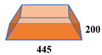
The Bogotá Metro Line 1 project in Colombia exemplifies the expansive reach of China’s infrastructure endeavors on a global scale (
Figure 1). Spanning an extensive 23.86 km, the project is segmented into various design-specified sections, including the beam-end segments, which demarcate the extremities of the bridge spans; the transitional gradient segments that facilitate grade adjustments; the standard midspan segments, which constitute the principal components of the span; and the midspan adjustment segments that ensure the bridge’s structural conformity with design variations. The scope of this investigation zeroes in on the standard midspan segment (Interpretation 01), which is integral to the overarching integrity and functionality of the bridge system (
Figure 2).
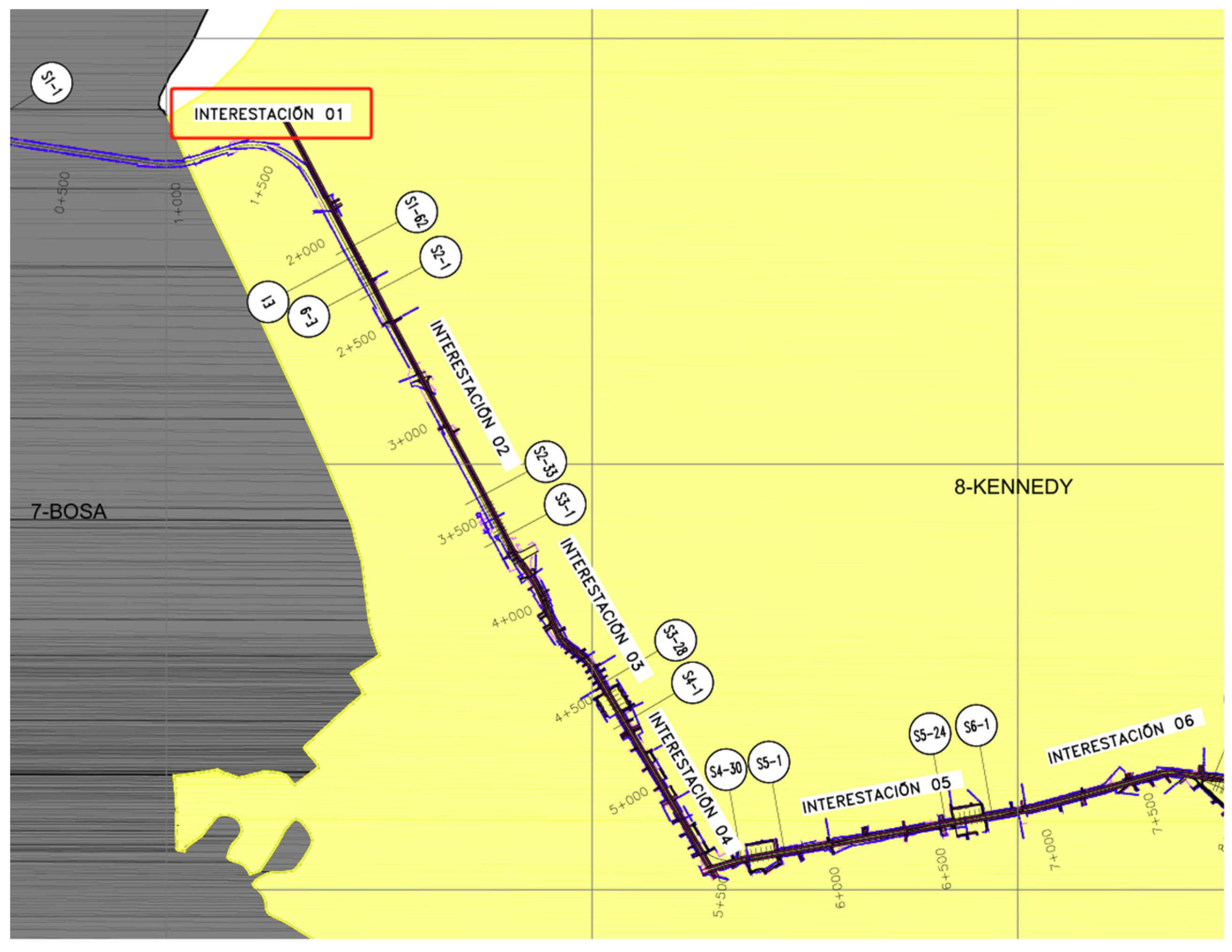
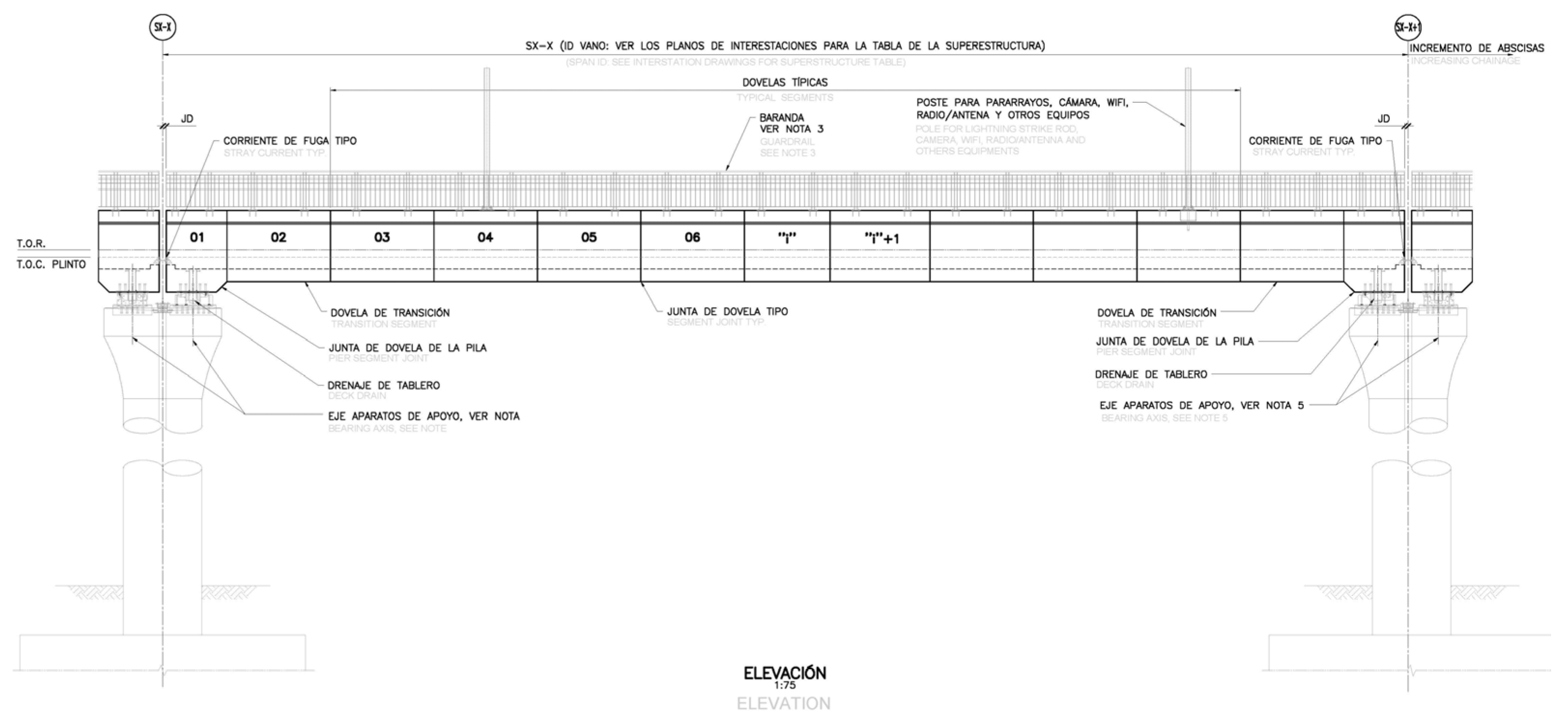
Figure 3 shows the side elevation of the standard beam section.
This paper puts forth an analysis of the standard midspan segments, as it is within these constituents that the intricacies of joint behavior under operational conditions are most pronounced. The segments are not merely passive elements but actively engage with loads and stresses, manifesting unique characteristics worthy of focused study. It is these characteristic responses that potentially hold the key to unlocking advancements in segmental bridge technology and, by extension, refining the praxis of bridge engineering. All information in this section comes from the actual bridge design, which has been implemented in practical engineering.
3. Finite Element Analysis Model
Finite element modeling of segmented U-beam bridges was executed via the utilization of advanced finite element software ABAQUS 6.14 [
26]. This study meticulously embodies the behavior of concrete by employing the material constitutive model founded on the stress–strain relationship delineated in Ref. [
27].
Furthermore, the parameters pertaining to the concrete plastic damage model are systematically catalogued in
Table 1, whilst
Table 2 elucidates the material parameters pertinent to both concrete and steel composites.
Table 3 shows the mesh details of FE simulation.
The quintessential component scrutinized within this treatise is the archetypal beam segment, as delineated in
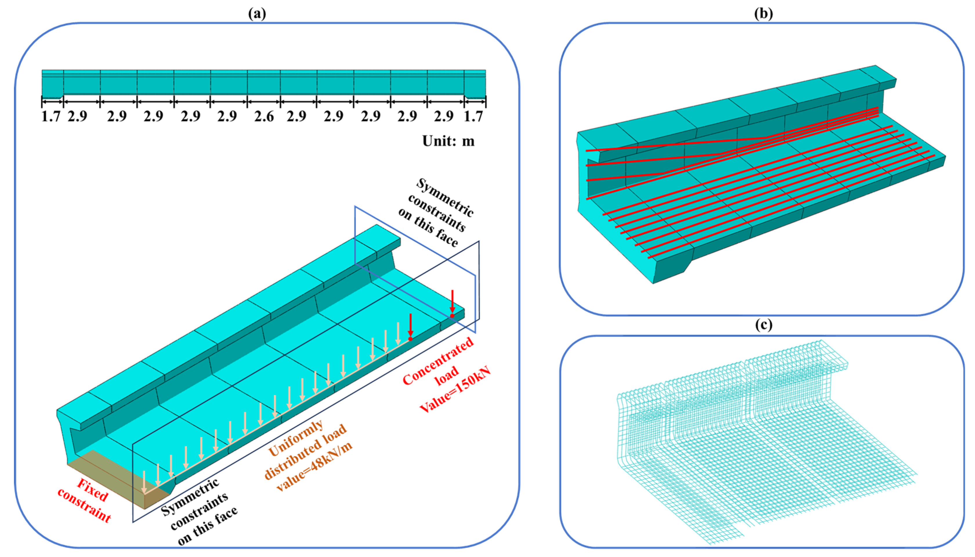
Figure 2. The aggregate length of the segmentally constructed bridge spans 35 m and comprises 13 individual beam elements, cumulatively constituting the entirety of the bridge’s structural framework. Owing to the intrinsically symmetrical nature of the design, a quarter-sectional analysis was conducted to enhance computational efficacy. The three-dimensional finite element representation of this quarter section is systematically illustrated in
Figure 4a. Boundary conditions encompass fixed constraints at the terminal sections of the beam, alongside symmetrical constraints enforced on the median lateral and longitudinal planes of the structure. Live loads were meticulously mapped and are exhibited in
Figure 4a, including a uniformly distributed load and two concentrated loads with values of 48 kN/m and 150 kN, respectively, congruent with the distribution and magnitudes anticipated under normal operational conditions. The design strength of concrete, steel bars, and steel strands is 50 MPa, 550 MPa, and 1860 MPa, respectively.
Within the domain of segmental bridge construction, the application of epoxy resin adhesive within the epoxy joints is critical, serving to reinforce the integrity of the structure. This reinforcing capacity manifests in twofold enhancements; it amplifies the overall load-bearing efficacy and augments the adhesive bonding strength at the joints. Comparatively, epoxy joints are deemed advantageous for augmenting structural stability over their joint counterparts. Upon failure of the shear keys, the epoxy resin adhesive plays a pivotal role in forestalling the dislocation of the interconnecting shear keys. While the incorporation of epoxy joints is acknowledged for bolstering the comprehensive load-bearing potencies of the bridge section, it is crucial to acknowledge that their contribution, though significant, remains relatively finite. Epoxy resin is generally very thin (around 10 mm) compared to the length of the beam section (9.6 m), and the interface friction model can be utilized to approximate the behavior of the epoxy resin interface. This approach has been validated as effective in prior refs. [
20,
28]. Moreover, the considerable thickness of the epoxy resin necessitates extremely fine local meshing, leading to a significant increase in calculation degrees of freedom. This can impact the efficiency of structural optimization. Hence, an approximate interface friction model is chosen as a solution.
Consequently, in evaluating the escalated shear bearing proficiencies afforded by epoxy resin adhesive, it is imperative to exercise circumspection in not overvaluing its impact. In pursuit of this objective, tie constraints are strategically implemented within the joint regions in the vicinities of shear keys. Therein, the normal and tangential responses are considered discretely in areas devoid of shear keys. For normal behavioral interactions, a hard-contact assumption is utilized, and for tangential interactions, the penalization approach is employed, adhering to the Coulomb contact friction framework, with an applied friction coefficient of 0.45 [
21].
4. Analysis of the Mechanical Behavior of Keys in Segmental U-Shaped Bridges
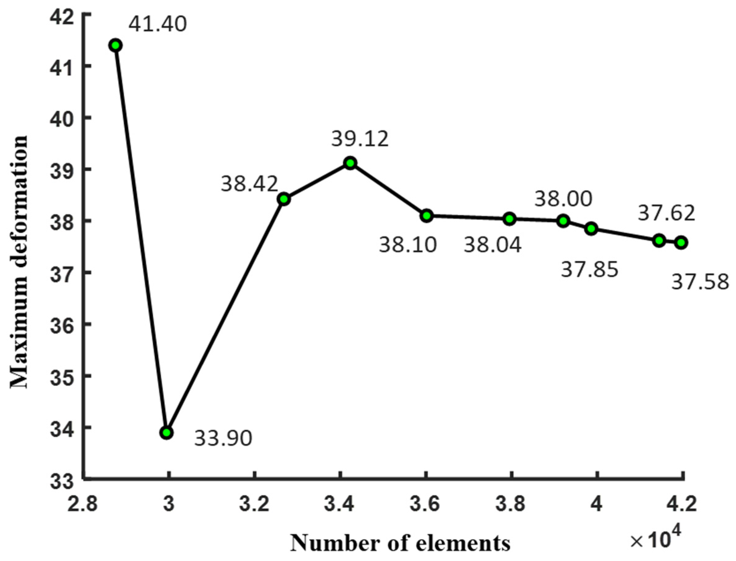
In order to verify the correctness of FE simulation in this paper, mesh convergence analysis was conducted, as shown in
Figure 5. We calculated different DOFs with the same FE model and the other conditions, using the maximum deformation as a vertical ordinate.
The configuration presented in
Figure 4b was duly earmarked for the mechanical behavioral analysis, with the contact surface key assembly configured in alignment with the specifications elucidated in
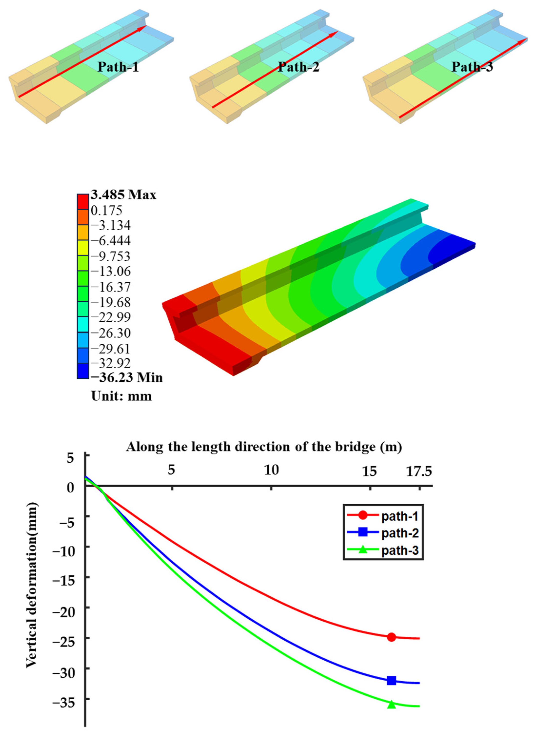
Figure 2. In concordance with the inherent properties of segmental bridges, a sophisticated optimization of the sectional keys is envisaged. Comprehensive and localized deformation patterns of the structure are systematically rendered in
Figure 6.
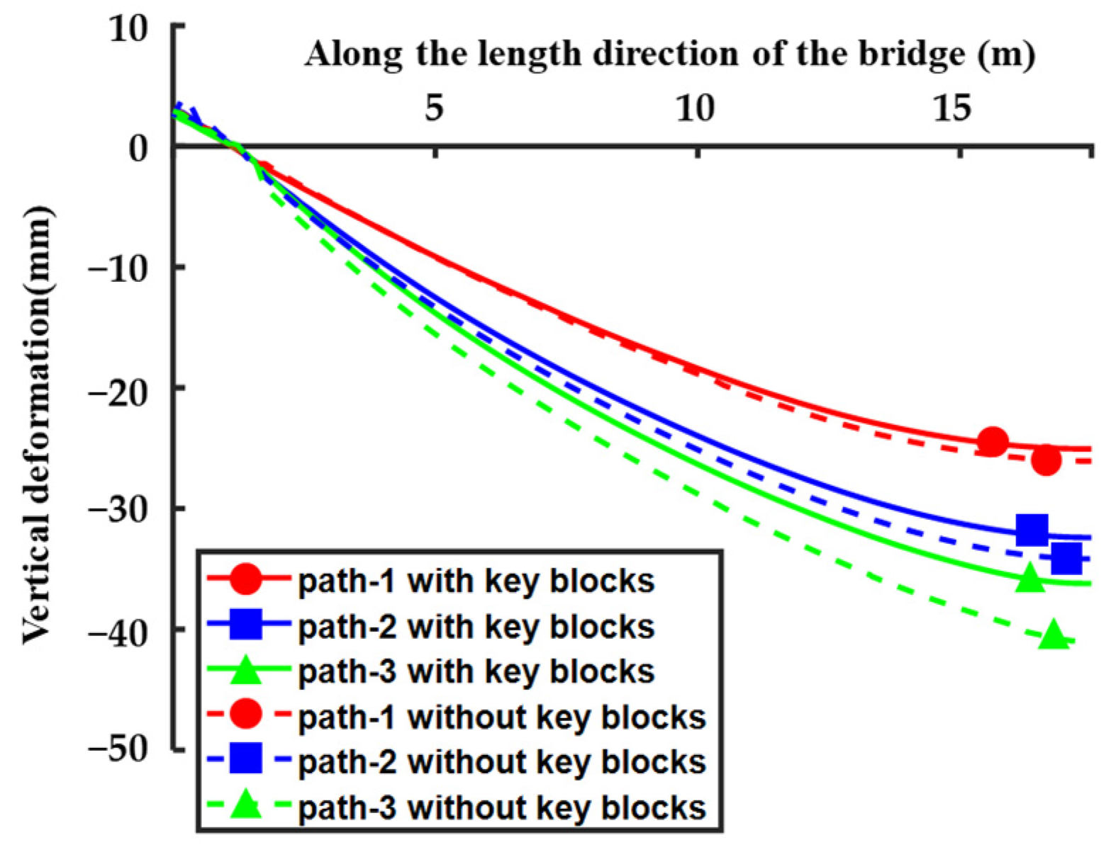
Through a detailed examination of the overarching and discrete deformation visualizations, it becomes apparent that under the impetus of applied prestress and superimposed loads, the beam’s utmost vertical deformation peaks at 36.23 mm, prominently positioned at the central axis of the segmental bridge. A trio of paths, each encompassing one-quarter of the bridge’s length, were employed to elucidate vertical deformation characteristics. Notably, the extremal pathway (Path-1) evidences a decrease in maximum vertical deformation by 11.14 mm when compared to the maximum deformation observed on the most internal path (Path-3), epitomizing a decline of approximately 30.78%. Such observations underscore a noteworthy disparity in deformation between the internal and external sections along the same longitudinal segment of the precast, segmental U-shaped bridge. This pronounced differential in deformation accentuates the asymmetrical distribution of stress, culminating in a decrement in structural load-bearing proficiency.
Figure 6 reveals that an upward deformation is manifest at the support points of the bridge structure. Despite the predominant downward deflection across the bridge’s expanse, an observable counter deformation arises at the points of support. Quantitatively, the measured upward deflection at the constrained extremity is 3.485 mm, a value which, though modest, is contrasted against the more substantial 36.23 mm downward deflection noted at the midpoint of the span. This contrast in deflection is attributable to the fixed constraints enforced at the terminus of the support. Collectively, these deformational responses within the segmental U-shaped bridge are deemed to be within acceptable structural behavior parameters.
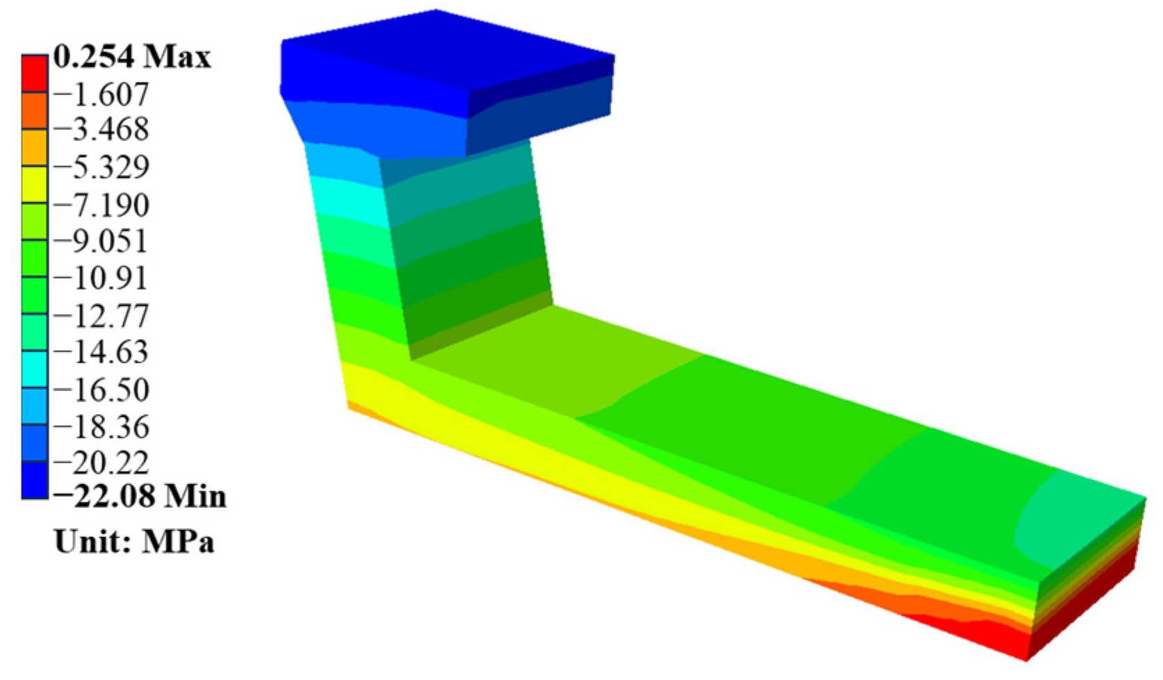
The stress profile of the midspan segment, as delineated in
Figure 7, reveals a maximum compressive stress registering at 22.67 MPa and a peak tensile stress of 0.275 MPa. These stresses occur predominantly at the upper flange plate and the lower extremity of the plate, respectively. The stress gradient along the midspan segment displays a nuanced gradation, initiating from the flange plate and progressively extending toward the central region of the lower plate. Observations confirm that the flange and web plates are entirely subject to compressive forces, while merely a marginal segment of the bottom plate’s midpoint is subjected to tensile forces, with the remainder of the bottom plate enduring compressive stresses.
The distribution pattern of stress within the midspan segment is characterized by maximal compressive stress at the flange plate, which incrementally diminishes across the web plate as it proceeds from the flange to the bottom plate. Thereafter, it undergoes a transitional phase, shifting from compressive to tensile stress at the lateral regions of the bottom plate. Attributable to the architectural properties of the U-shaped beam, the web plate possesses enhanced flexural rigidity, contrasting with the bottom plate’s relatively reduced stiffness in flexure. Consequently, the midspan segment is subject to advantageous compressive conditions in proximity to the web plate, while tensional forces, which are generally less favorable to the concrete matrix, prevail within the domain of the bottom plate.
An in-depth analysis was undertaken to discern the impact of keys on the vertical deformation and stress modality of segmental U-shaped bridges. This research considered a hypothetical model devoid of keys at the junctures of the segments, with reliance placed solely upon prestressing to ensure segment coherence. The configuration of the overall deformation is presented in
Figure 8 and bears resemblance to the previously computed outcome. Comparative vertical deformation profiles for three paths, mapped in
Figure 6, depict dashed lines indicative of the keyless juncture scenario, whilst solid lines represent the prior condition inclusive of keys.
Examination of
Figure 8 delineates an augmented downward vertical deformation of the structure in the absence of keys when juxtaposed with the keyed assembly. Notably, the principal vertical deformation along the innermost path manifested a 12% increment, underscoring the pivotal role of keys in moderating the extremity of downward vertical deformation across the structure.
Furthermore,
Figure 9 offers insight into the stress contours of the midspan segment. In the absence of keys at the sectional junctures, no significant change in the maximum tensile stress within the midspan segment was observed. These findings attest to the integral influence of keys upon the stress distribution within the midspan segment.
In summary, the integration of keys holds substantial sway over the deformational and stress-related characteristics within segmental bridges. Their presence is indelibly critical and, as such, necessitates thorough joint key analysis within the domain of bridge engineering.
5. Optimization Analysis of Joint Shear Capacity
In this section, we conduct a parametric study involving systematically varying and analyzing multiple parameters to understand their individual and collective impacts on a system or phenomenon.
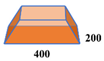
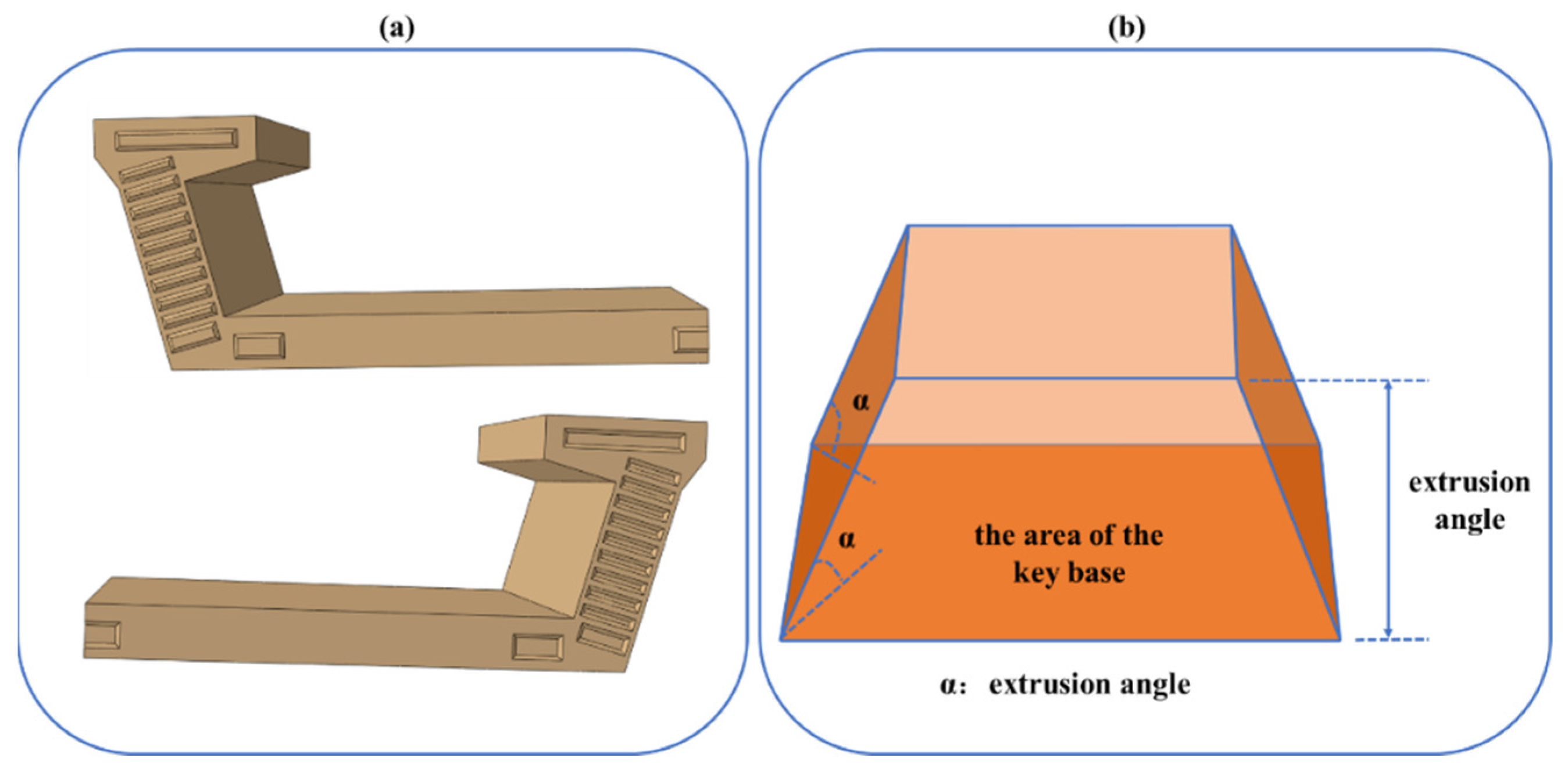
Figure 10 delineates the configuration of segmental keys, where frustum-shaped keys are strategically interspaced at the interstices of the joints. The principal controlling parameters governing the key design encompass the basal area of the key, the acuteness of the extrusion angle, and the profoundness of the extrusion depth. A comprehensive exploration of the mechanical comportment of segmental U-shaped bridges will be conducted through an exhaustive finite element simulation analysis. This investigation will scrutinize an array of key control parameters to ascertain their influence on the structural dynamics of the bridges.
5.1. The Influence of the Position Distribution of Keys
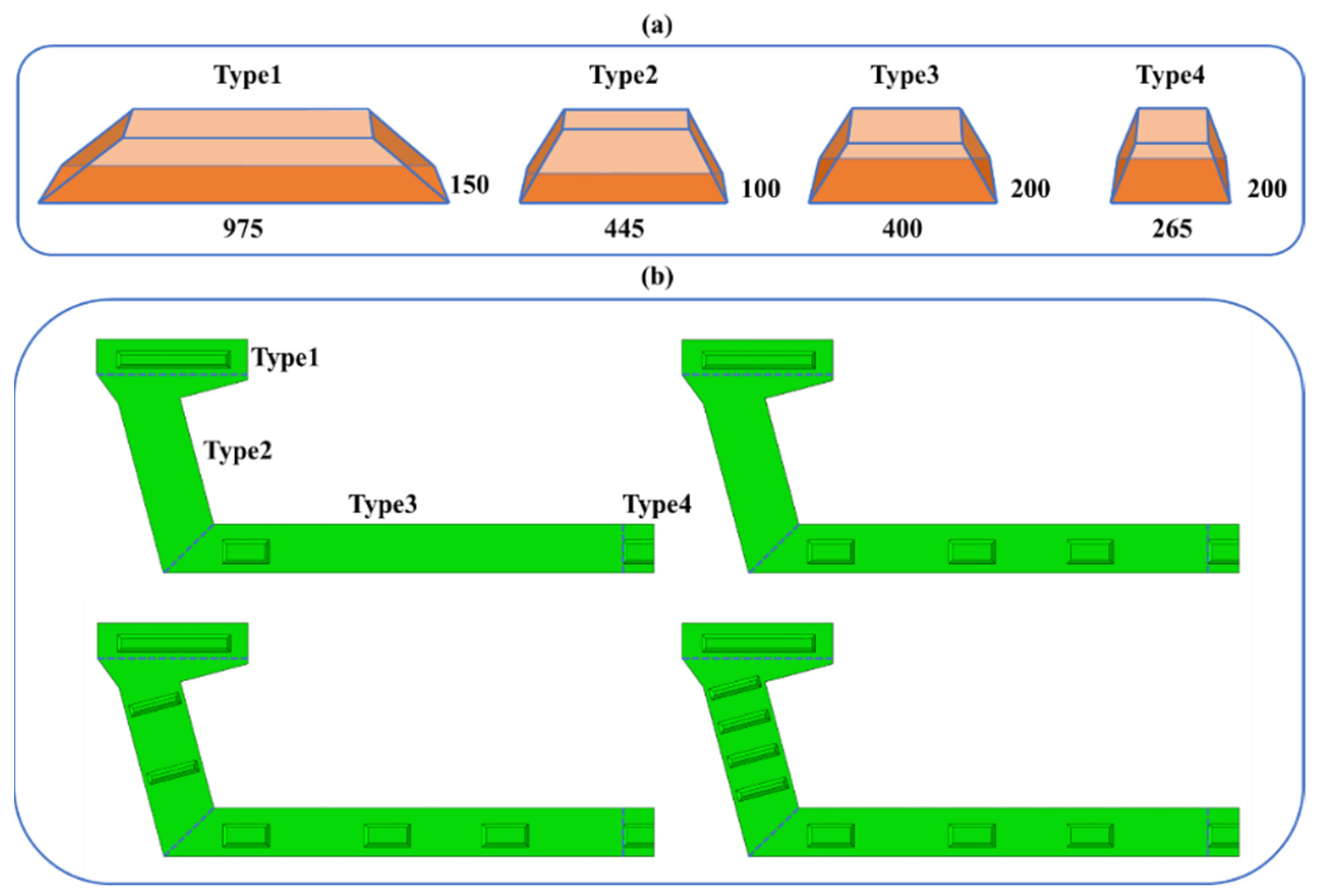
The present study embarks on an analytical investigation into the role of key positional distribution on the mechanical attributes of the bridge. In an endeavor to optimize key placement in relation to the intrinsic characteristics of the U-shaped girder, diverse keys are positioned within distinct segments of the cross-section, namely the flange, web, and bottom plates. We delineated four variant configurations of key arrangements, as illustrated in
Figure 11a.
For each semi-section, arrangements of 3, 5, 7, and 9 keys are embraced (which correspond to total arrangements of 5, 9, 13, and 17 keys per entire cross-section), with the key configurations arrayed symmetrically relative to the central longitudinal axis of the section. Among the four key types, variances are solely observed in the dimensions of the key base, enumerated as 975 × 150 mm
2, 445 × 100 mm
2, 400 × 200 mm
2, and 265 × 200 mm
2, respectively. Conversely, the extrusion angle and depth are maintained constant across all variants at −45° and 32 mm, respectively. The aforementioned keys are allocated within different zones of the cross-section, as explicated in
Figure 11b.
Subsequent to the finite element method (FEM) analysis, which contemplated the trajectory as depicted in
Figure 12b, the repercussions of key position distributions for the cumulative structural deformation are revealed in
Figure 12a, providing an insight into the structural implications of key placement.
This study engages in examining the reinforcement imparted by epoxy joints within the section. Frictional contact is presupposed for areas bereft of keys, while bonded contact is utilized where keys are present. Findings depicted in
Figure 12 elucidate that an increment in the count of keys correlates with a decrease in the maximum deformation observed in the segmental bridge, alongside a concurrent increase in overall structural stiffness. Thus, an increase in key quantity is instrumental in minimizing maximum deformation.
With a mere triad of keys on the half-section, the utmost observed vertical deformation reaches 41.79 mm. The incorporation of an additional duo of keys to the half-section’s bottom plate reduces the peak vertical deformation to 40.34 mm, which equates to a modest decline of 3.35%. Conversely, the addition of two keys to the web plate precipitates a marked diminution in peak vertical deformation, plummeting to 37.47 mm, or a decrement of 7.11%. Advancing this configuration with an additional pair of keys on the web plate further mitigates the maximal vertical deformation to 36.03 mm, representing a further 3.84% reduction in maximum deformation. These outcomes suggest that the strategic placement of keys on the web plate of a segmental U-shaped bridge is significant in augmenting overall stiffness. It is discernible that the absence of keys on the web plate impinges negatively on structural rigidity. Supplementing keys to those extant on either the web or bottom plates can substantially elevate stiffness. Hence, a strategy of proliferating the key count is recommended.
Stress contours within the midspan segments under varying key positional distributions were ascertained and are depicted in
Figure 13. Observational evidence indicates that as keys are progressively added, the maximum tensile stress within the midspan segment undergoes a nominal decrease, and the tensile region conspicuously contracts towards the center of the bottom plate. The maximal compressive stress evidenced in the midspan segment exhibits a slight decrement concurrent with the rising key count. Collectively, the midspan segment is characterized by a stress state where the bottom plate sustains minimal tensile stresses, while the flange plate and web plate predominantly bear compressive stresses. Despite the presence of zones subjected to tensile stress, their magnitudes remain relatively minimal. This pattern demonstrates that an escalation in the number of keys within the segmental U-shaped bridge contributes beneficially to the contraction of the tensile zone.
The present inquiry delves into the shear capacity of segmental U-shaped bridge joints by applying the shear capacity formula endorsed by the American Association of State Highway and Transportation Officials (AASHTO) [
29]. The shear capacity is computed as per the following equation:
where
represents the overall area of the key base;
denotes the standard compressive strength of concrete, with
= 50 MPa considered in this case;
indicates the average compressive stress of the contact section of different segments; and
represents the contact area of different segments, excluding the contact area of the key. The outcomes of the shear capacity for disparate key distributions calculated by means of Equation (1) are cataloged within
Table 4.
Inspection of
Table 4 reveals an association between an ascended count of keys and amplified shear capacity. Specifically, the inauguration of keys into the web plate, when none was previously present, markedly augments the shear capacity.
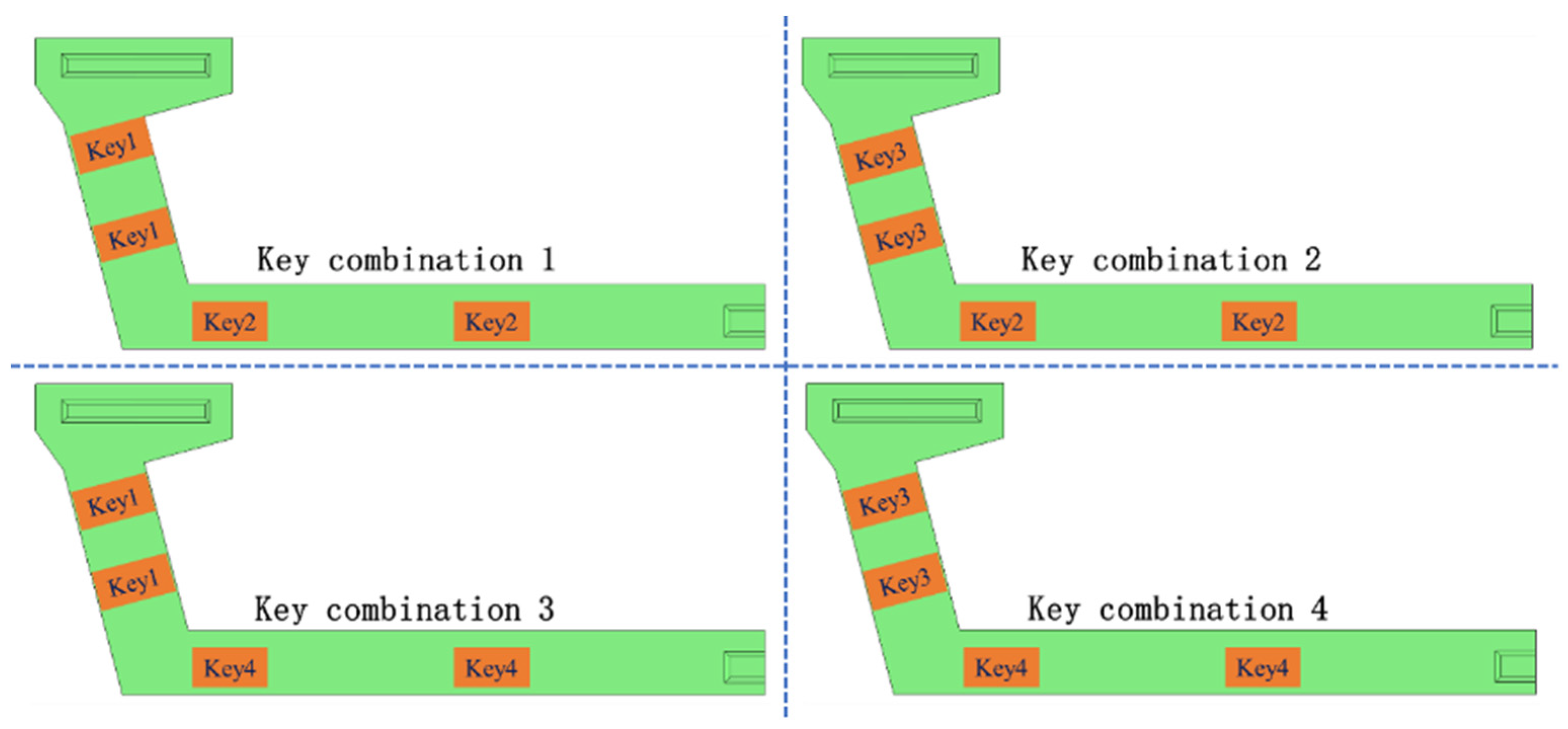
5.2. The Influence of the Size of Keys
This analysis was expanded to assess the impact of key dimensions on the mechanical behavior of segmental U-shaped bridges. Modifying the two types of keys depicted in
Figure 11b, with base areas originally measuring 445 × 100 mm
2 and 400 × 200 mm
2, to new dimensions of 445 × 200 mm
2 and 600 × 200 mm
2, we labeled these modifications as Key1, Key2, Key3, and Key4, as detailed in
Table 5. Subsequently, these keys were coupled to create four distinct sections, as demonstrated in
Figure 14.
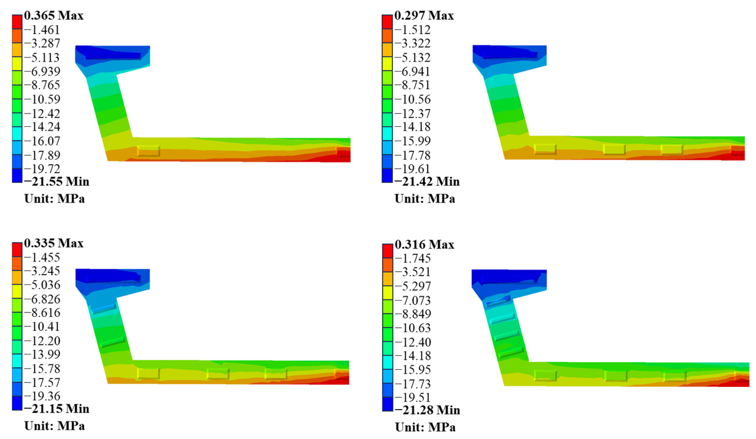
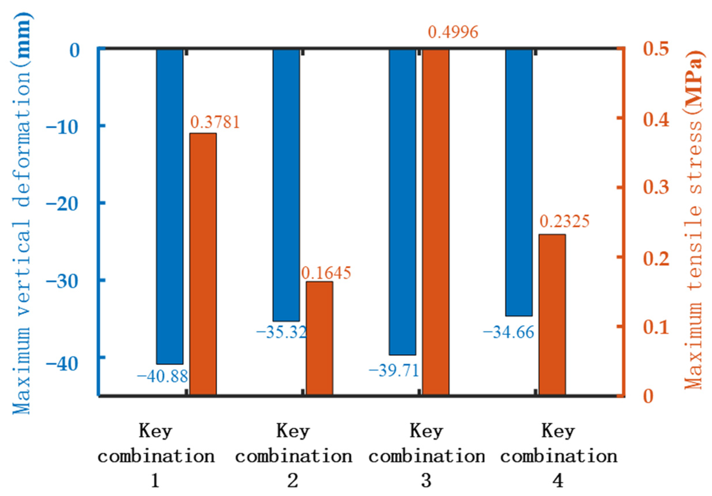
The quantification of the maximum vertical deformation of the segment bridges with varied key sizes, alongside the peak tensile stress within midspan segments, is presented in
Figure 15. Analysis of
Figure 15 indicates that an increase in key size within the web plate substantially diminishes the maximum vertical deformation. For example, an analysis of key combinations 1 and 2 reveals that maximum vertical deformation plummets from 40.88 mm to 35.32 mm, corresponding to a significant reduction of 13.6%. Similarly, an evaluation of key combinations 3 and 4 illustrates that maximum vertical deformation reduces from 39.71 mm to 34.66 mm, corresponding to a notable reduction of 12.7%. However, augmenting the key size in the bottom plate also leads to a decrease in maximum vertical deformation, although the reduction is comparatively marginal. As demonstrated by comparing key combinations 1 and 3, as well as 2 and 4, the maximum vertical deformation is curtailed slightly by 2.86% and 1.87%, respectively. Hence, it is evident that increasing the key size in the web plate section is a more effective strategy to significantly curtail maximum vertical deformation.
Employing Equation (1) as a computational model, the assessment of shear capacity for varied configurations of key dimensions is tabulated in
Table 6. An evaluation of this table reveals that the amplification of key dimensions within the web plate substantively bolsters shear capacity. For illustrative purposes, an analysis of key combinations 1 and 2, which incorporates an enlarged key within the web plate, yields an escalation in shear capacity from 22.5 MN to 28.1 MN, reflecting an approximate increment of 20%. Upon comparing key combinations 3 and 4, the shear capacity is observed to swell from 25.6 MN to 29.9 MN, equivocating to a rise of roughly 14%.
Although augmenting the dimensions of keys in the bottom plate does confer improvements in shear capacity, the degree of such enhancements is quantifiably inferior to the enhancements achieved by enlarging keys in the web plate. When juxtaposing key combinations 1 and 3, as well as combinations 2 and 4, the shear capacity undergoes an upsurge from 22.5 MN to 25.6 MN and from 28.1 MN to 29.9 MN, respectively, with incremental increases of 12% and 6%, respectively. Ergo, these findings punctuate the dual merits of upscaling key size, as it serves not only to mitigate maximum vertical deformation but also to fortify shear capacity.
In contrast to the key configuration delineated in
Section 4, the maximum vertical deformation corresponding to key composition 4 introduced in the present section stands at 34.66 mm. Furthermore, such an arrangement of the keys efficaciously diminishes the consumption of concrete material. With regard to the quantity of keys, the arrangement herein proposed necessitates a mere six keys, and consequently, the area encompassed by the keys contracts from 0.72 m
2 to 0.617 m
2, equating to a diminution of 14.3%. This unequivocally illustrates that judicious configuration of keys contributes substantially to the reduction in maximum vertical deformation in segmental U-shaped bridges.
6. Conclusions
In this research, the mechanical behavior and joint shear capacity optimization of glued keys in segmental U-shaped bridges were developed. The accuracy of the calculation results was ensured through mesh convergence analysis. While there no experiments were carried out, the research findings of this article can still provide theoretical guidance for practical engineering. The main conclusions of this article are summarized as follows.
This investigation conclusively underscores the symptomatic sensitivity of segmental U-beam bridges to the spatial distribution and dimensional specifics of joint keys. The finite element analysis within ABAQUS 6.14 substantiates that keys are integral in restricting vertical deformation. The deployment of larger keys in the web plate resulted in a significant reduction in the maximum vertical deformation and a corresponding boost to the bridge’s shear capacity. By refining key design parameters such as size and distribution, the optimized configurations elucidated in this paper not only offer improved structural performance but also yield material savings. As urban infrastructure continues to grow in complexity, the findings of this study will be instrumental for engineering professionals aiming to optimize bridge designs for both efficiency and longevity, substantiating the U-beam’s viability as a superior alternative within the matrix of contemporary bridge engineering solutions.
In order to further apply the reported results in engineering practice, further work should involve conducting laboratory experiments to validate the finite element simulations. This will yield more precise insights into the practicality of the proposed FE models compared to the current study, thereby enhancing the accuracy of the findings.


