Abstract
In this paper, an innovative infill wall is proposed and examined experimentally and parametrically. The proposed wall has an innovative design and is constructed with lightweight concrete strengthened by waste glass. The proposed wall not only demonstrates robust performance against out-of-plane loading, but also exhibits exceptional behavior under elevated temperatures. Additionally, the necessary equations used to predict the wall’s behavior are also presented. The results reveal that glass powders affect weight loss. During the initial temperature application, ranging up to 600 °C, specimens with 0% and 8% glass powder experienced maximum and minimum weight loss, respectively. At 200 °C, glass powder concentrations below 4% caused a reduction in compressive strength, , while concentrations between 4% and 8% led to an increase in . Consequently, the optimal glass powder volume was determined to be 6% for specimens under varying temperature conditions. The out-of-plane loading tests indicated that although the wall was exposed to heat up to 800 °C, the resistance did not decrease significantly. Given its role as a non-load-bearing wall without the application of gravity, this innovative structure is anticipated to perform admirably in fire scenarios during seismic events.
1. Introduction
In accordance with the American Society of Civil Engineers (ASCE) [1], infill walls are typically classified as non-structural elements, playing a secondary role in several building types. These non-structural walls have found widespread application in residential, office, commercial, and other construction projects. Despite their common use, past seismic events have highlighted the vulnerability of infill walls under seismic loading conditions, as depicted in Figure 1, showcasing instances of damaged infilled walls. The repercussions extend beyond seismic events, impacting the overall structural behavior of buildings. In addition to seismic vulnerability, infill walls cause adverse structural effects, such as reduced natural periods [2,3], shear fractures in connections [4], the formation of short columns susceptible to shear loads [5,6], and the creation of soft stories [7,8]. In recognizing these shortcomings, researchers have sought novel methods to mitigate the undesirable impacts of infill walls on structural behavior [9].
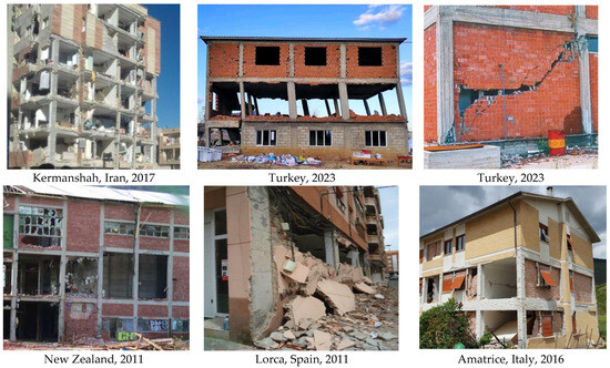
Figure 1.
Damaged infill wall in past earthquakes [10,11,12].
Among the various innovative approaches, strengthening using fiber-reinforced polymers (FRPs) [13,14,15] or steel sheets [16] stands out as superior. Although these methods improve the infill walls, they do not have a considerable effect on the negative impact of the infill wall on structures. Also, they impose additional costs on structural construction methods that, most of the time, are not economical. Separating (isolating) the infill wall from the main frame is used as a simple and effective method that has a significant effect on improving the behavior of the structure [17]. Simple and effective methods, such as the use of flexible brick at the wall–frame junction [18] or complete isolation using elastomeric U-profiles [19], have shown promise but tend to increase construction expenses.
Tang and co-workers [20] confirmed that crumb rubber made of waste tires reduces damage to recycled aggregate concrete under high temperatures. Also, the optimum amount of rubber was reported. Consequently, Ref. [21] reported that a rubber content of more than 4% is not recommended considering the mechanical and fracture performance.
While these methods enhance the behavior of infill walls, they are particularly susceptible to fire hazards. Although anti-flame coatings offer partial solutions, their economic viability is questionable, especially for residential buildings. A straightforward and cost-effective approach involves the use of light-expanded clay aggregate (LECA) blocks, isolated from the frame. Regular hollow concrete blocks (RHCBs), meeting ASTM C90 standards [22], are suitable for infill walls (Figure 2). Despite the advantages of RHCB, such as low weight, their deficient fire resistance remains a critical drawback. In contemporary structural design, fire resistance is a pivotal consideration, necessitating evaluation through standardized tests [23,24] or semi-empirical methods [25,26,27,28,29].
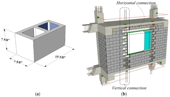
Figure 2.
(a) Regular hollow concrete blocks based on ASTM C90 [19] and (b) the fabrication of the wall.
In light of these considerations, this paper proposes an innovative wall system utilizing the benefits of LECA blocks, including lightweight construction and sound resistance. The proposed design addresses the inherent weakness of weak connections in traditional LECA block walls. Furthermore, waste glass is incorporated to enhance the wall’s fire resistance, not only contributing to environmental sustainability but also anticipated improvements in performance under high-temperature conditions.
2. The Proposed Infill Wall
As illustrated in Figure 3, the proposed wall design boasts simplicity in its fabrication. The horizontal interlocking of blocks is anticipated to establish a robust connection, fortifying the joints against lateral loading. This secure joint minimizes the vulnerability of both mortar and adhesive connections to fire damage, ensuring the wall remains structurally stable and does not succumb to its weight during a fire event. Furthermore, owing to the lightweight nature of these concrete blocks, the constructed walls are categorized as lightweight walls. The blocks, consisting of three layers, contribute to the enhanced thermal and acoustic insulation of the wall, along with increased resistance to fire. The incorporation of waste glass powder in the block manufacturing process is pivotal to these improvements. When exposed to high temperatures, the glass powder undergoes melting, augmenting the overall strength of the wall. It is crucial to note that this paper considers the glass-to-cement ratio as a significant parameter in achieving optimal results. Beyond the technical enhancements to wall behavior, the utilization of waste glass aligns with environmental considerations. Glass, being a non-degradable material in nature, is deemed environmentally harmful. The incorporation of waste glass into the construction process not only improves the wall’s performance but also aids in the removal of this non-degradable material from the environment, contributing positively to environmental sustainability [30,31,32,33,34]. No special technology is needed to produce these types of blocks. First, the combined materials are poured into framework blocks. Then, the concrete curing is carried out the same as the lightweight blocks.
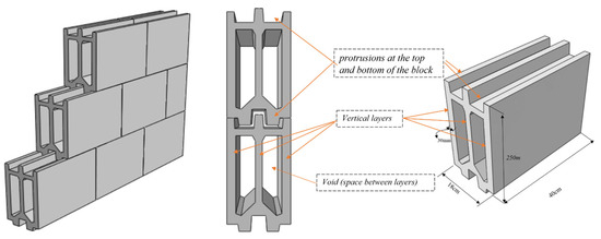
Figure 3.
The geometry of the proposed block.
The introduction of a small gap between the proposed wall and the columns of the boundary structure serves to isolate them, effectively preventing the transmission of forces from the wall to the boundary frame, as illustrated in Figure 4. Consequently, the wall only experiences a minimal out-of-plane (OOP) seismic force owing to the lightweight nature of the blocks employed in its construction. The weight of the wall is calculated as follows:
where L, H, and t are the length, height, and thickness of the wall, respectively. Also, 850 is the specific weight of the wall (in kg/m). Based on the seismic risk or area that the wall is built on, the applied force to the wall is calculated as , where C is the seismic coefficient.
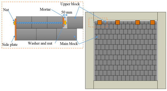
Figure 4.
The reinforcing system of the wall.
For reinforcing the wall either with rebar or plate under pure shear, according to the AISC 341-16 [29], the equation must be satisfied. In this equation, Vu is the required shear strength using LRFD load combinations, while Vn is the nominal strength that is calculated as the following:
and is the resistance factor that equals 1. Also, , Fy is the yielding stress, and Aw is the cross-section of the plate or rebar parallel to the shear load applied. Therefore, this equation can be simplified as follows:
Further, to control the inside plate for bending purposes (flexural design), the equation must be satisfied where Mu is the required flexural strength which is calculated as , Mn is the nominal flexural strength that is calculated using (where ), Rn is nominal strength, and is the resistance factor that equals 0.9. So, , can be expressed as the following:
3. Experimental Study
3.1. Materials
To investigate the influence of glass powder (made of waste bottle glass) on the mechanical properties of LECA blocks, an experimental study was conducted. Five different concrete mix designs were tested, as outlined in Table 1. The composition for all specimens included a 100 N/m3 superplasticizer (P200-3R), Portland cement type I, and glass powder with particle diameters less than 80 microns. The numerical suffix at the end of each model name indicates the glass-powder-to-cement ratio relative to the SP-0 model.

Table 1.
Materials’ properties.
3.2. Compressive and Tensile Test Procedure
To determine the compressive strength, the average of results from three standard cylinder specimens was utilized. The specimens underwent testing at temperatures of 20 °C, 200 °C, 400 °C, 600 °C, and 900 °C, amounting to a total of 60 models tested at each temperature. With evaluations conducted under five temperature conditions (Tu), a comprehensive set of 300 specimens was tested to determine the optimal mix design for the materials. Figure 5 provides an overview of the test setup and equipment used in the experimental study. The curing process was carried out under laboratory conditions, and all specimens were tested after 28 days. Before applying the compressive load, temperature control was meticulously managed using an automatic oven, as depicted in Figure 6. This controlled heating regime ensured consistent and accurate temperature conditions during the testing process.
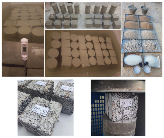
Figure 5.
The view of the specimens and equipment.
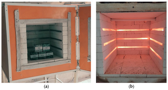
Figure 6.
Temperature application setup: (a) prepared specimen used for testing and (b) the temperature application oven.
3.3. Sequence of Temperature Application to the Specimens
As depicted in Figure 7, the specified temperature regime outlined in the preceding section was applied to the specimens. The notation T0 denotes the ambient temperature. The figure illustrates the time intervals (t1) corresponding to specific temperature points: 20 min for t1 = 20 °C, 20 min for t1 = 200 °C, 65 min for t1 = 400 °C, 105 min for t1 = 600 °C, and 155 min for t1 = 900 °C.
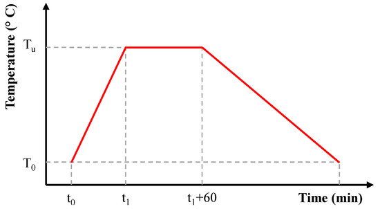
Figure 7.
The applied temperature sequence.
3.4. Direct Fire Application Procedure
To assess the impact of direct fire exposure on the blocks, a series of tests were conducted, as depicted in Figure 8. The blocks were subjected to direct fire for approximately one hour. The primary objective of the test was to evaluate the block’s response when one side was exposed to fire. The results aim to determine whether the block can withstand the effects of fire and whether it exhibits heat transmission or resistance, as elaborated upon in the subsequent sections.
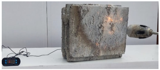
Figure 8.
The appliance of direct fire to the block.
3.5. Testing of the Constructed Wall under OOP Loading
Due to a significant reduction in the out-of-plane (OOP) strength of walls after exposure to fire, a test was conducted on a wall subjected to OOP loading following a temperature of 900 °C. The behavior of the wall was evaluated using a block containing 6% glass powder (GP) under OOP loading conditions. The choice of 900 °C was dictated by the limitations of the testing equipment. The tests were conducted on walls measuring 1000 × 1000 mm, as illustrated in Figure 9. A pure moment was applied at each length, accounting for ¼ of the total wall length, up to the wall’s ultimate failure. Throughout the loading process, deflection was monitored using attached strain gauges at the mid-length of the wall.
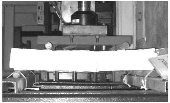
Figure 9.
Experimental test for OOP loading.
4. Results and Discussion
4.1. Weight Loss
As illustrated in Figure 10, the weight loss of all specimens can be characterized by three distinct segments: the first segment corresponding to , the second segment encompassed by , and the third stage pertaining to . In the first segment, the maximum weight loss was observed, followed by a relatively minor weight loss in the second segment. In the third segment, although weight loss was still evident, the rate of decline was less pronounced compared to the first segment. Referring to Figure 10, the weight loss reached 0.81, ranged from 0.73 to 0.76, and ranged from 0.68 to 0.61 in the first, second, and third segments, respectively. Additionally, it is noteworthy that SP8 exhibited the maximum weight loss among the specimens.
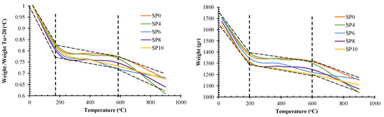
Figure 10.
The temperature versus the weight of the specimens.
Therefore, by fitting the results, Equation (5a,b) are proposed to predict the weight of the specimen under different temperatures.
To assess the accuracy of the proposed equation, a comparison was made between the results obtained from the equation and the actual test results, as illustrated in Figure 11. The error of the proposed equation was found to be within the range of −5% to +5%, indicating a close alignment between the predicted values and the experimental data. This suggests that the proposed equation provides a reasonably accurate estimation of the weight loss of the specimens under different temperature conditions.
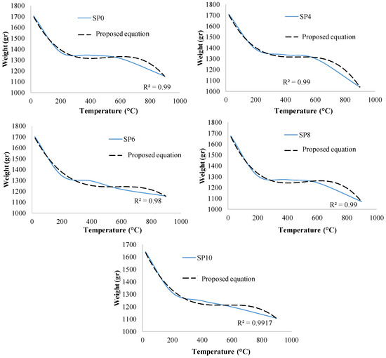
Figure 11.
Comparing the proposed relation with the test results.
4.2. The Compressive Strength of Specimens
In Table 2, the compressive strength, , of the specimens is documented based on the influence of glass powder at elevated temperatures. The table reveals that by increasing the to (instead of decreasing), the for SP6 and SP10 exhibited an enhancement. Additionally, a comparison of the results indicates that at lower temperatures, the addition of glass powder enhanced the compressive strength of the specimens. This observation is visually represented in Figure 12, where the results are plotted. The figure demonstrates distinct behaviors for specimens at different values. For low temperatures, the maximum was measured with 8% glass powder. However, at high temperatures, the specimen with 6% glass powder attained the maximum . For glass powder concentrations less than 4%, the impact of on the was negligible; nonetheless, the maximum was achieved at .
Table 2.
The compressive strength, , and weight versus the temperature.
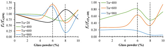
Figure 12.
The glass powder and temperature effect on the .
To predict the of the specimen under different , the following equations are proposed. According to the equations, first, the is calculated, and then its relation to the glass power (GP) ratio at different is calculated. The proposed equations exhibit good agreement with the test results, with the maximum error being less than 2%. In these equations, GP represents the glass powder. The results obtained from Equation (6a–d) are compared with the test results in Figure 13.
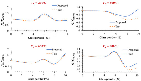
Figure 13.
Comparing the test results with proposed Equation (6a–d).
4.3. Tensile Strength of Specimens
To analyze the tensile strength () of the specimens, both and related to different glass powders (GPs) for various temperatures are plotted in Figure 14. Across all specimens with GP values less than approximately 5% at different , exceeded . However, for GP values around 5% and approximately 7%, and were similar for and , respectively. Notably, the maximum and minimum values of and were observed with GP values at 8% for all .
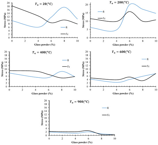
Figure 14.
Comparison of compressive and tensile strength in relation to different temperatures.
4.4. Wall Testing
4.4.1. General
Taking into account the compressive strength, tensile strength, and weight loss of specimens, it is evident that the mixture design incorporating 6% glass powder offers superior performance. To further assess the wall, blocks made of SP-6 were fabricated and subjected to testing, as elaborated upon in the subsequent sections.
4.4.2. The Block under Direct Fire
The block underwent testing under direct fire conditions, as depicted in Figure 15. Notably, the presence of two vertical holes on three sides of the block was intended to impede the transfer of heat. Figure 16 illustrates the temperature profiles at the front (the side facing the fire) and back of the block. Small cracks began to appear in the block at the 58 min mark, as indicated in Figure 15. It is noteworthy that the block exhibited commendable performance by sustaining approximately one hour without significant cracking under the applied fire conditions.
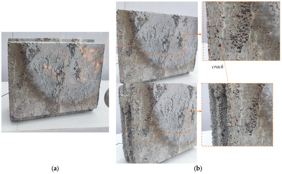
Figure 15.
The proposed block: (a) during applied direct fire and (b) after 58 min under direct fire.
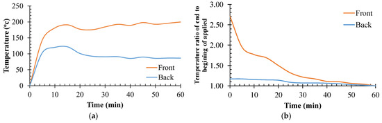
Figure 16.
Heat transfer through the block: (a) temperature-versus-time diagram and (b) temperature ratio of blocks’ sides versus time.
In Figure 16, the temperature profiles at the front (direct fire) and back of the block are presented. As expected, the heat at the front of the block was higher than at the back. Notably, a significant finding is that the temperature at the back of the block was reduced by a substantial margin, ranging from 28% to 57%. Towards the end of the applied fire (time = 58 min), the temperature at the front was 2.71 times the initial value (time = 5 min), while the ratio for the back of the block was approximately 1.17 times the initial value. The presence of two voids created by the middle layer of the block contributed to this favorable performance against heat transmission.
4.4.3. Constructed Wall under OOP Loading
Figure 17 depicts the examined wall following exposure to a temperature of 900 °C. The figure illustrates that the proposed wall exhibited commendable performance against high temperatures. The results reveal that cracks appeared at a displacement of 12 mm for the proposed wall. The ultimate OOP strength of the wall was recorded at 18.81 kN. With a load of 1.67 kN, the wall exhibited a weight-to-strength ratio of approximately 11.17 times its weight perpendicular to the plane, indicating significant structural integrity. This ratio suggests that even when exposed to temperatures up to 900 °C, the resistance perpendicular to the plate does not experience a substantial decrease. Given that this wall serves as a non-load-bearing structure and is not subjected to gravitational forces, it is expected to perform well during fires induced by seismic events.
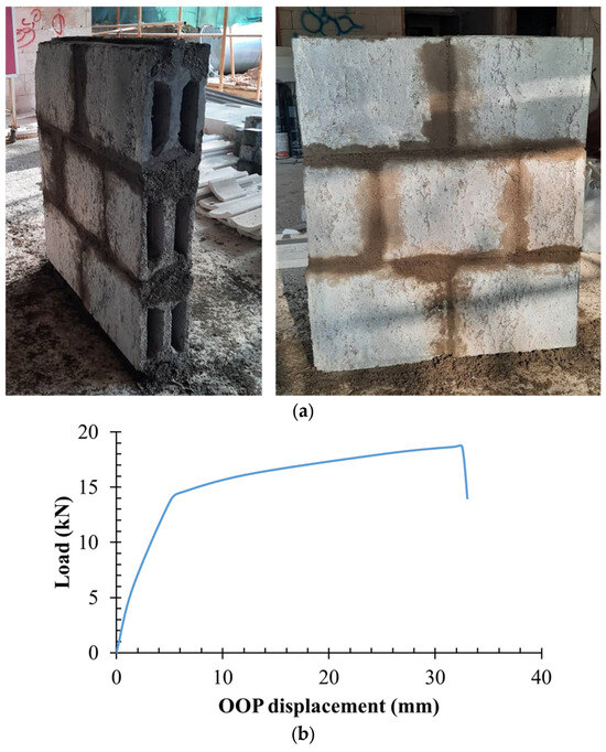
Figure 17.
Wall testing: (a) views of the constructed wall and (b) load–deflection curve.
5. Conclusions
In this paper, the experimental and parametric investigation of an innovative infill wall constructed from lightweight concrete and waste glass powder was conducted, yielding the following key findings.
- The glass powder percentage influenced weight loss during temperature exposure. The maximum and minimum weight losses were observed for specimens with 0% and 8% glass powder, respectively, up to 600 °C. Beyond 600 °C, specimens with 4% glass powder exhibited the highest weight loss.
- The results indicated that by increasing the temperature, was reduced. Moreover, glass powder affected the . A noticeable finding is that under ambient temperatures, Tu = 20 °C, adding the glass powder reduced the , whereas under higher Tu, it improved the .
- At Tu = 200 °C, glass powder less than 4% reduced the , and in glass powder ranging from 4% to 8%, it increased the . Therefore, the optimal volume of glass powder was measured as 6% for specimens under different temperatures.
- Another noticeable finding is that the slob of reduction corresponding to the Tu was different. Up to heating of 200 °C, the was reduced by around 25%. From 200 °C to 600 °C, reduction tended to be around 10%. After Tu = 600 °C, the maximum reduction was obtained for SP4 and SP8.
- With the exception of models under Tu = 200 °C, temperature reduced the tensile strength of specimens. Models with 4% glass powder exhibited the minimum tensile strength for all evaluated temperatures.
- At Tu = 200 °C, the tension strength considerably increased when the glass powder was 6%. For other temperatures, the optimum glass powder was 8%.
- Testing the proposed block under direct fire indicated that the block prevents heat transfer. The temperature at the front of the back was reduced from 28% to 57%, which is considerable. At the beginning of applying the heating, the heat reduction percentage was 28%, and this improved to 57% at the end of testing.
- The ultimate out-of-plane (OOP) strength of the wall was 18.81 kN, while the wall’s weight was 167 kg, resulting in a weight-to-strength ratio of approximately 11.17 times its weight perpendicular to the plane. This indicates robust structural integrity even under exposure to temperatures up to 800 °C. As the wall was designed as a non-load-bearing structure without gravitational forces, it showed promising performance in fire events during earthquakes.
Author Contributions
Conceptualization, A.G. and A.P.; methodology, A.G.; validation, A.P. and A.A.; formal analysis, A.G., V.K.K. and A.A.; investigation, A.G. and A.P.; resources, A.P.; writing—original draft preparation, A.G. and A.P.; writing—review and editing, V.K.K.; visualization, A.G. and V.K.K.; supervision, A.P.; project administration, A.P.; funding acquisition, A.P. All authors have read and agreed to the published version of the manuscript.
Funding
The research was financed using funds from the Main School of Fire Service in Warsaw under the subsidy for research potential UPB/21/000778.
Data Availability Statement
The data presented in this study are available upon reasonable request from the corresponding author. The data are not publicly available due to regulation of Main School of Fire Service in Warsaw and IAU as well.
Conflicts of Interest
The authors declare no conflicts of interest.
References
- American Society of Civil Engineers. Minimum Design Loads and Associated Criteria for Buildings and Other Structures, ASCE/SEI 7–22; American Society of Civil Engineers: Reston, VA, USA, 2022. [Google Scholar]
- Amanat, K.M.; Hoque, E. A Rationale for Determining the Natural Period of RC Building Frames Having Infill. Eng. Struct. 2006, 28, 495–502. [Google Scholar] [CrossRef]
- Mirrashid, M.; Naderpour, H. Computational Intelligence-Based Models for Estimating the Fundamental Period of Infilled Reinforced Concrete Frames. J. Build. Eng. 2022, 46, 103456. [Google Scholar] [CrossRef]
- Moreira, R.F.; Varum, H.; Castro, J.M. Influence of Masonry Infill Walls on the Seismic Assessment of Non-Seismically Designed RC Framed Structures. Buildings 2023, 13, 1148. [Google Scholar] [CrossRef]
- Jin, H. Comparative Study on the Effects of Infill Walls on Reinforced Concrete Frame Structures. Appl. Mech. Mater. 2015, 730, 81–84. [Google Scholar] [CrossRef]
- Nour, A.; Bourdim, S.M.E.-A.; Hassaine, M.I.E.T. Evaluation of the Seismic Behavior of RC Buildings through the Direct Modeling of Masonry Infill Walls. Buildings 2023, 13, 1576. [Google Scholar] [CrossRef]
- Grubišić, M.; Šipoš, T.K.; Grubišić, A.; Pervan, B. Testing of Damaged Single-Bay Reinforced Concrete Frames Strengthened with Masonry Infill Walls. Buildings 2023, 13, 1021. [Google Scholar] [CrossRef]
- Saengyuan, S.; Latcharote, P. Investigation of Seismic Performance for Low-Rise RC Buildings with Different Patterns of Infill Walls. Buildings 2022, 12, 1351. [Google Scholar] [CrossRef]
- Dineț, A.; Cobîrzan, N.; Maghiar, M. The Influence of Infills Made of Different Clay Units on Structural Behavior of Framed Buildings Placed in Different Seismic Areas. Procedia Manuf. 2020, 46, 116–121. [Google Scholar] [CrossRef]
- Dizhur, D.; Walsh, K.Q.; Giongo, I.; Derakhshan, H.; Ingham, J. Out-of-Plane Proof Testing of Masonry Infill Walls. Structures 2018, 15, 244–258. [Google Scholar] [CrossRef]
- Hermanns, L.K.H.; Fraile de Lerma, A.; Alarcón Álvarez, E.; Álvarez Cabal, R. Performance of Masonry Buildings during the 2011 Lorca Earthquake. In Proceedings of the 15th World Conference on Earthquake Engineering, Lisbon, Portugal, 24–28 September 2012. [Google Scholar]
- Fragomeli, A.; Galasco, A.; Graziotti, F.; Guerrini, G.; Kallioras, S.; Magenes, G.; Malomo, D.; Mandirola, M.; Manzini, C.F.; Marchesi, B.; et al. Comportamento Degli Edifici in Muratura Nella Sequenza Sismica Dell’Italia Centrale Del 2016—Parte 1: Quadro Generale. Progett. Sismica 2017, 8, 49–74. [Google Scholar] [CrossRef]
- Li, Y.; Ning, Z.; Shan, H.; Gao, C.; Huang, S. Seismic Behavior of Steel Frame Infilled with Wall-Panels Connected by Sliding Joint. J. Constr. Steel Res. 2024, 212, 108253. [Google Scholar] [CrossRef]
- Tekeli, H.; Kusain, F.E.; Anıl, Ö. Experimental Behavior of Masonry Infilled RC Frames with Openings Strengthened by Using CFRP Strip. Compos. Struct. 2023, 312, 116873. [Google Scholar] [CrossRef]
- Yu, J.-C.; Feng, X.; Carvelli, V. Hysteretic Performance of Foam-Infilled Corrugated FRP-Steel Sandwich Shear Wall. Eng. Struct. 2023, 294, 116775. [Google Scholar] [CrossRef]
- Shan, S.; Li, S. Collapse Performance of Post-Tensioned Steel Frames Considering Influence of Infill Walls. Structures 2023, 58, 105427. [Google Scholar] [CrossRef]
- Jin, W.; Zhai, C.; Zhang, M.; Liu, W.L.; Wei, Y.; Xie, L. Experimental Investigation on the In-Plane and out-of-Plane Interaction of Isolated Infills in RC Frames. Eng. Struct. 2023, 293, 116569. [Google Scholar] [CrossRef]
- Pallarés, F.J.; Rubio, L.P. Experimental Study on the Response of Seismically Isolated Masonry Infilled Steel Frames during the Initial Stages of a Seismic Movement. Eng. Struct. 2016, 129, 44–53. [Google Scholar] [CrossRef]
- Marinković, M.; Butenweg, C. Innovative system for earthquake resistant masonry infill walls. In Proceedings of the 16th European Conference on Earthquake Engineering, Thessaloniki, Greece, 18–21 June 2018. [Google Scholar]
- Tang, Y.; Wang, Y.; Wu, D.; Chen, M.; Pang, L.; Sun, J.; Feng, W.; Wang, X. Exploring temperature-resilient recycled aggregate concrete with waste rubber: An experimental and multi-objective optimization analysis. Rev. Adv. Mater. Sci. 2023, 62, 20230347. [Google Scholar] [CrossRef]
- Tang, Y.; Feng, W.; Chen, Z.; Nong, Y.; Guan, S.; Sun, J. Fracture behavior of a sustainable material: Recycled concrete with waste crumb rubber subjected to elevated temperatures. J. Clean. Prod. 2021, 318, 128553. [Google Scholar] [CrossRef]
- ASTM C90-14; Standard Specification for Loadbearing Concrete Masonry Units. ASTM International: West Conshohocken, PA, USA, 2014.
- EN 1363-1:2012; Fire Resistance Tests—Part 1: General Requirements. CEN: Brussels, Belgium, 2012.
- ASTM E119—10a; Standard Test Methods for Fire Tests of Building Construction and Materials. ASTM International: West Conshohocken, PA, USA, 2010.
- Lawrence, S. Design of Clay Masonry Walls for Fire Resistance; Technical Notes; Think Brick Australia: St. Leonards, Australia, 2006. [Google Scholar]
- Powęzka, A.; Ogrodnik, P.; Szulej, J.; Pecio, M. Glass Cullet as Additive to New Sustainable Composites Based on Alumina Binder. Energies 2021, 14, 3423. [Google Scholar] [CrossRef]
- Powęzka, A.; Szulej, J.; Ogrodnik, P. Reuse of Heat Resistant Glass Cullet in Cement Composites Subjected to Thermal Load. Materials 2020, 13, 4434. [Google Scholar] [CrossRef]
- Powęzka, A.; Szulej, J.; Ogrodnik, P. Effect of High Temperatures on the Impact Strength of Concrete Based on Recycled Aggregate Made of Heat-Resistant Cullet. Materials 2020, 13, 465. [Google Scholar] [CrossRef] [PubMed]
- Powęzka, A.; Ogrodnik, P.; Biedugnis, S.; Szulej, J. Assessment of Selected Parameters of Concrete Composite Containing Recyclate Obtained from Fire-Resistant Cullet. J. Phys. 2019, 1398, 012011. [Google Scholar] [CrossRef]
- ANSI/AISC 341–16; Seismic Provisions for Structural Steel Buildings. American Institute of Steel Construction (AISC): Chicago, IL, USA, 2016.
- Cobîrzan, N.; Muntean, R.; Thalmaier, G.; Felseghi, R.-A. Recycling of Mining Waste in the Production of Masonry Units. Materials 2022, 15, 594. [Google Scholar] [CrossRef] [PubMed]
- Grădinaru, C.M.; Muntean, R.; Șerbănoiu, A.A.; Ciocan, V.; Burlacu, A. Sustainable Development of Human Society in Terms of Natural Depleting Resources Preservation Using Natural Renewable Raw Materials in a Novel Ecological Material Production. Sustainability 2020, 12, 2651. [Google Scholar] [CrossRef]
- Rodsin, K.; Ali, N.; Joyklad, P.; Chaiyasarn, K.; Al Zand, A.W.; Hussain, Q. Improving Stress-Strain Behavior of Waste Aggregate Concrete Using Affordable Glass Fiber Reinforced Polymer (GFRP) Composites. Sustainability 2022, 14, 6611. [Google Scholar] [CrossRef]
- Shcherban’, E.M.; Stel’makh, S.A.; Beskopylny, A.N.; Mailyan, L.R.; Meskhi, B.; Elshaeva, D.; Chernil’nik, A.; Mailyan, A.L.; Ananova, O. Eco-Friendly Sustainable Concrete and Mortar Using Coal Dust Waste. Materials 2023, 16, 6604. [Google Scholar] [CrossRef]
Disclaimer/Publisher’s Note: The statements, opinions and data contained in all publications are solely those of the individual author(s) and contributor(s) and not of MDPI and/or the editor(s). MDPI and/or the editor(s) disclaim responsibility for any injury to people or property resulting from any ideas, methods, instructions or products referred to in the content. |
© 2024 by the authors. Licensee MDPI, Basel, Switzerland. This article is an open access article distributed under the terms and conditions of the Creative Commons Attribution (CC BY) license (https://creativecommons.org/licenses/by/4.0/).