Article

Design and Hysteretic Performance Analysis of a Novel Multi-Layer Self-Centering Damper with Shape Memory Alloy

1
School of Civil Engineering, Xi’an University of Architecture & Technology, Xi’an 710055, China
2
China Coal Xi’an Design Engineering Co., Ltd., Xi’an 710055, China
3
XAUAT Engineering Technology Co., Ltd., Xi’an 710055, China
4
Key Laboratory of Structural Engineering and Earthquake Resistance, Ministry of Education, Xi’an 710055, China
*
Author to whom correspondence should be addressed.
Buildings 2024, 14(2), 483; https://doi.org/10.3390/buildings14020483
Submission received: 16 January 2024 / Revised: 3 February 2024 / Accepted: 5 February 2024 / Published: 8 February 2024

Abstract

:
This paper presented the development process of a novel multi-layer self-centering damper utilizing a NiTi shape memory alloy (SMA) with remarkable superelastic properties. The construction and operating principles of the novel damping device were introduced. A model for calculating the restoring force–displacement hysteretic curve of the novel damper was established, and based on this theoretical model, a parameter analysis of the damper’s hysteresis performance was conducted. The effect of SMA pre-strain, SMA diameter, number of layers in the damper, and number of SMA wires per layer on the damper’s stiffness, the unit cycle energy dissipation, and the equivalent viscous damping ratio were investigated, respectively. The results showed that the restoring force–displacement hysteretic curve of the novel SMA damper exhibits a full spindle shape, demonstrating the damper’s excellent energy dissipation capacity, self-centering capability, significant stroke, and unique variable stiffness characteristics (i.e., appropriate initial stiffness, minimal isolation stiffness, and significant limit stiffness). The results also indicated that the SMA pre-strain has a minor impact on the damper’s stiffness but a significant influence on unit cyclic energy dissipation and equivalent damping ratio. As the SMA pre-strain increased from 0.03 to 0.04, 0.05, and 0.06, the maximum stroke of the damper continuously decreases, while the unit cyclic energy dissipation initially increases and then decreases, with the optimal energy dissipation achieved at a pre-strain of 0.04. Increasing the SMA diameter results in a higher damper stiffness and energy dissipation capacity, with no significant change in maximum stroke and equivalent damping ratio. Increasing the number of damper layers leads to an increase in maximum stroke and unit-cycle energy dissipation, accompanied by a decrease in stiffness and almost constant equivalent damping ratio. As the number of SMA wires per layer increased from 8 to 16 and 32, the maximum stroke and equivalent damping ratio presented little variation, but the damper’s stiffness and unit cyclic energy dissipation continuously increased.

1. Introduction

In the field of civil and architectural engineering, structures are inevitably subjected to various types of vibrational loads, such as wind loads, seismic loads, and explosive impact loads. Traditional seismic-resistant structures typically rely on the plastic deformation of structural elements to dissipate energy in order to meet deformation and vibration energy dissipation requirements [1,2]. For structures with specific usage requirements, such as nuclear power plant containment structures and liquid storage tanks, excessive structural damage or excessive structural vibration response is unacceptable. Therefore, structural vibration control becomes critically important. Isolation and energy dissipation techniques are commonly used in the field of structural vibration control. In these techniques, the focus is often on developing dampers suitable for various specialized engineering conditions [3,4,5].
Shape memory alloy (SMA) is a novel functional material known for its remarkable shape memory characteristics and superelastic properties. The superelasticity of SMAs refers to the occurrence of both forward and reverse phase transformations between austenite and martensite induced by the application and removal of stress. This results in a complete hysteresis loop in the SMA stress–strain curve, providing excellent energy dissipation and damping properties at the material level [6,7]. Developing dampers using the superelasticity of SMAs enables effective energy dissipation and deformation recovery. Furthermore, these dampers offer advantages such as a larger deformation capacity, variable stiffness, self-centering capability, high-temperature resistance, corrosion resistance, and fatigue resistance when compared to other types of dampers [8].
Researchers have proposed various vibration dampers based on the superelastic properties of SMAs. Peng et al. [9] introduced an SMA central lead-type damper and established a theoretical analysis of the damper’s damping characteristics and device design method. Li et al. [9] proposed two types of SMA energy dissipators, namely, the tensile and scissor types, and validated their vibration reduction effects through seismic simulation shake table tests. Yu et al. [10], Chen et al. [11], and Huang et al. [12] presented three different types of SMA displacement amplification dampers and conducted comparative studies of their seismic performance through numerical examples. Parulekar et al. [13], Li et al. [14], and Li et al. [15] introduced three different forms of tubular SMA dampers. Xue et al. [16], Ren et al. [17], and Qian et al. [18] combined SMA resetting devices and friction energy dissipation devices to develop several types of composite SMA friction dampers and conducted experimental research. Sun and Li [19] designed multi-dimensional SMA dampers that provide damping in both tension, compression, and torsion directions. Qiu et al. [20] combined SMA bolts and friction to propose an SMA sliding friction damper. Wang et al. [21] developed a novel SMA circular spring and introduced a self-centering damper. Each of the above-mentioned SMA dampers often has unique advantages and limitations. For example, most SMA displacement amplification dampers utilize leverage principles to make full use of SMA recoverable strains. However, the presence of amplification mechanisms means that such dampers are typically only suitable for in-plane energy dissipation in frames and lack multi-axial functionality. Various tubular SMA dampers and SMA composite friction dampers have advantages such as simple structure and reliable force transmission but are generally only suitable for uniaxial tension–compression applications. Therefore, considering specific engineering conditions and the superelastic properties of shape memory alloys, developing superelastic SMA dampers that are suitable for unique working conditions, exhibit excellent performance, and have simple and reliable structures is of significant practical significance for the wider application of isolation and energy dissipation techniques.
In a vibration control engineering project for a tall and flexible structure subjected to horizontal seismic loads with an acceleration amplitude of 0.3 g, the horizontal acceleration response at the base of the structure should not exceed 0.03 g, and the maximum inter-story displacement amplitude should not surpass 300 mm. To meet these criteria, a hybrid control technique was considered, involving a combination of base isolation and energy dissipation methods. The base isolation should be achieved through the use of rolling ball isolation bearings. The dampers used for energy dissipation and vibration reduction must meet various technical specifications, including compact installation, omnidirectional functionality, adjustable stiffness, and self-centering capabilities after seismic events. Considering the specific characteristics of this engineering project, a novel multi-layer self-centering damper with shape memory alloy was developed.
This research project focuses on the development and analysis of a specialized SMA-based damper system to meet the seismic control requirements of a tall, flexible structure, with a combination of base isolation and energy dissipation techniques. The basic structure design and operational principles of the multi-layer self-centering SMA damper were introduced at first. Subsequently, the model for calculating the restoring force–displacement hysteretic curve of the damper was established. Finally, the paper conducted an analysis of the hysteresis performance parameters and investigated how factors such as SMA tensile strain, SMA diameter, the number of damper layers, and the number of SMA wires in each layer affected the damper’s hysteresis performance.

2. Damping Device Construction and Operating Principles

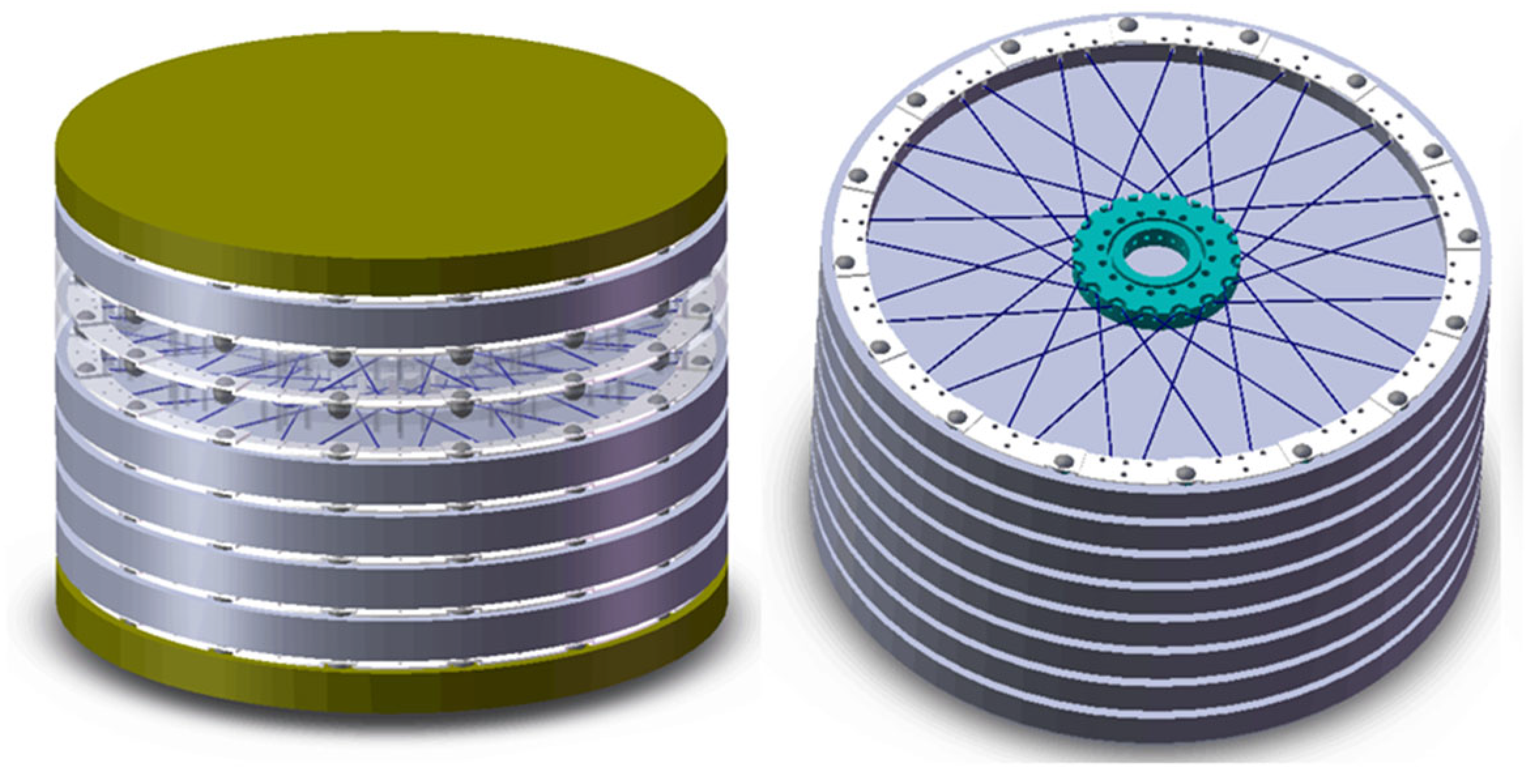
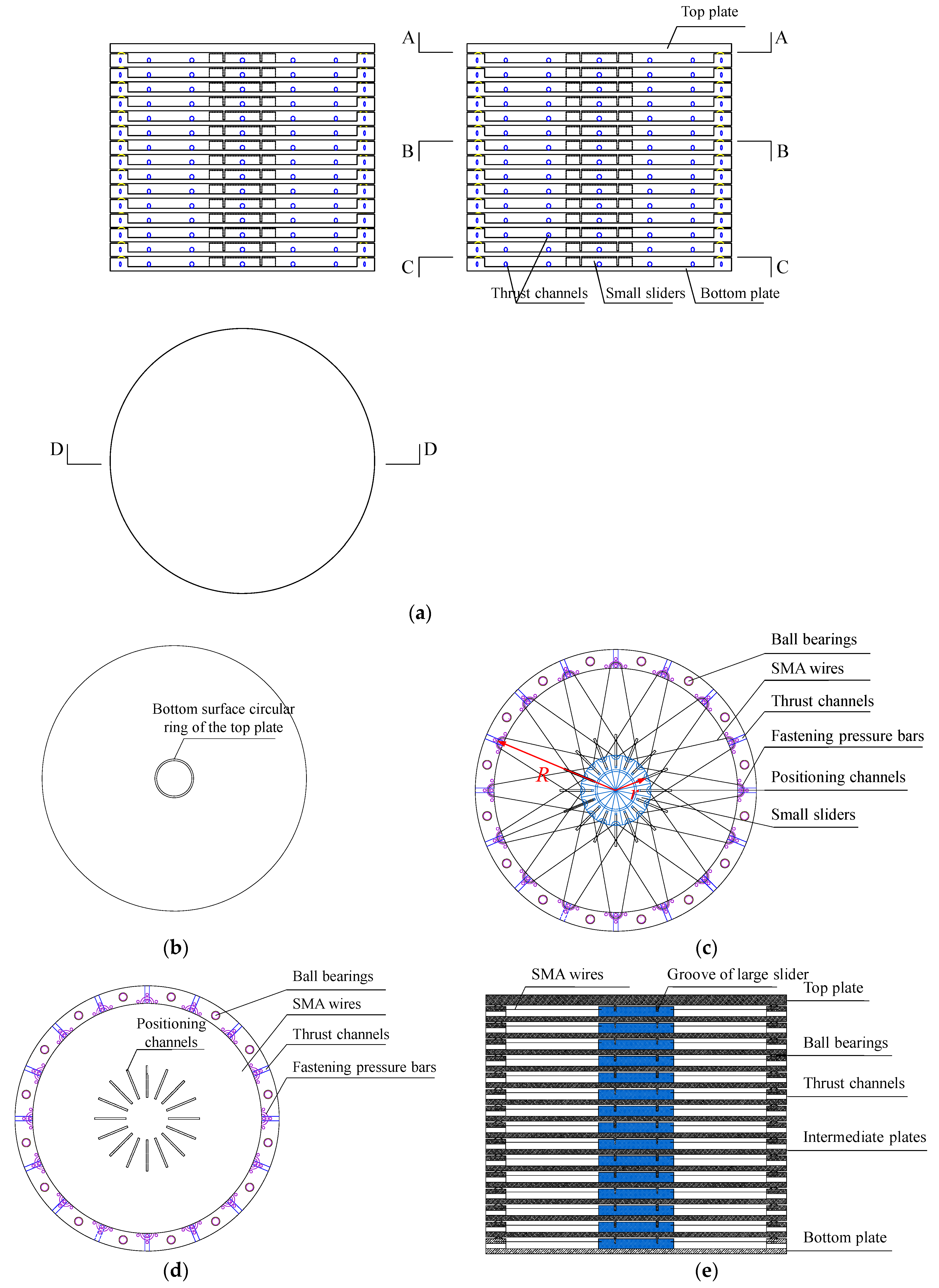
2.1. Damping Device Construction

Figure 1 and Figure 2 depict the 3D conceptual, orthographic, and sectional illustration of the multi-layer self-centring SMA damper, respectively. As shown in Figure 1 and Figure 2, this damper is in the form of a layered cylinder, consisting of a top plate, intermediate plates, a bottom plate, ball bearings, fastening pressure bars, small sliders, positioning channels, thrust channels, and SMA wires. The assembly sequence is as follows:
Step 1. Assemble from bottom to top. First, secure sixteen sector-shaped small sliders to the top surface of the damper’s bottom plate using positioning channels and temporary pins.
Step 2. Place ball bearings into the grooves on the bottom plate of the damper, which serve to reduce friction between layers.
Step 3. Thread the SMA wires through the outer rim of the damper’s bottom plate and the curved grooves on the sector-shaped small sliders, and then secure the SMA wires using fastening pressure bars.
Step 4. Insert the thrust screws into the thrust channels on the damper’s bottom plate and rotate them to push the sixteen sector-shaped small sliders to the end of the positioning channels. This forms a circular large slider and stretches the SMA wires to achieve the desired strain. Adjust the initial position of the sector-shaped small sliders to control the initial tension of the SMA wires.
Step 5. Insert the bottom surface circular ring of the intermediate plate into the pre-made groove on the circular large slider, and then release the sixteen thrust bolts. This completes the installation of the bottom layer of the damper.
Step 6. Repeat the above steps until you insert the bottom surface circular ring of the top plate into the corresponding groove of the lower circular large slider to complete the installation of the entire damper.
By using the above method, the number of damper layers, the number of SMA wires, the diameter of the SMA wires, and the pre-tension strain of the SMA wires can be adjusted according to actual working conditions.

2.2. Operating Principles of the Damper

The damper is in the form of a layered cylinder, and it can be symmetrically positioned between vibration isolation layers, forming a high-performance vibration isolation and damping system with spherical vibration isolation mounts. The bottom plate of the damper is connected to the lower plate of the vibration isolation layer using welding or bolt connections. The top plate of the damper has circular openings and is vertically connected to the upper plate of the vibration isolation layer using vertical pins. This means that the damper does not bear vertical loads from the upper structure, and the top plate of the damper and the upper plate of the vibration isolation layer can move vertically independently. These two components transfer the damping force horizontally through the vertical pins.
When the bottom plate of the damper moves together with the lower plate of the vibration isolation layer, the circular ring at the bottom of the upper plate drives horizontal movement between the large circular slider and the adjacent lower plates, as shown in Figure 2c. The circular large slider is composed of 16 fan-shaped small sliders, and it undergoes horizontal movement with the large circular disc below it. This movement inevitably causes some of the SMA wires, which are initially pre-tensioned, to experience loading, while others experience unloading during the reciprocating movement. During this process, energy is dissipated through the phase transition of the SMA wires. After the external vibration excitation ends, there may still be some displacement in the vibration isolation layer. Relying on the superelastic properties of the SMA wires, the upper and lower plates of the damper tend to return to their initial state, i.e., the damper automatically restores the upper structure to its original position.

2.3. Advantages of the Novel Damper

This novel damper offers the following advantages:
(1)
Effective energy dissipation: It possesses excellent energy dissipation capabilities, reducing the transmission of vibration energy from the bottom of the vibration isolation layer to the upper structure, thus lowering the vibration response of the upper structure.
(2)
Compact and adjustable design: The stacked arrangement allows the damper to maintain a relatively large and adjustable stroke within the limited space of the vibration isolation layer.
(3)
Variable stiffness characteristics: By carefully setting the diameter, quantity, and tensile strain of shape memory wires in each layer, the damper can achieve variable stiffness characteristics. It possesses some initial stiffness to prevent frequent structural oscillations during normal use, minimal vibration isolation stiffness to reduce upper structure vibration responses, and significant limiting stiffness to prevent excessive displacement of vibration isolation mounts, which could lead to structural overturning.
(4)
Excellent self-restoring ability: The symmetrically arranged shape memory alloy wires utilize their inherent superelastic properties to return the structure to its original position after external vibration excitations cease. This feature helps reduce or eliminate residual deformation in the vibration isolation layer.
(5)
High-temperature resistance, corrosion resistance, and fatigue resistance: The damper is capable of withstanding harsh environmental conditions, meeting the requirements of adverse operating environments.
(6)
Simple construction and easy installation: It has a straightforward design and is easy to install, making it suitable for a wide range of passive control applications in civil engineering.
These qualities make the damper a valuable component for passive control in civil engineering, effectively reducing structural vibrations and enhancing overall stability.

3. Restoring Force-Displacement Hysteretic Curve Calculation Model

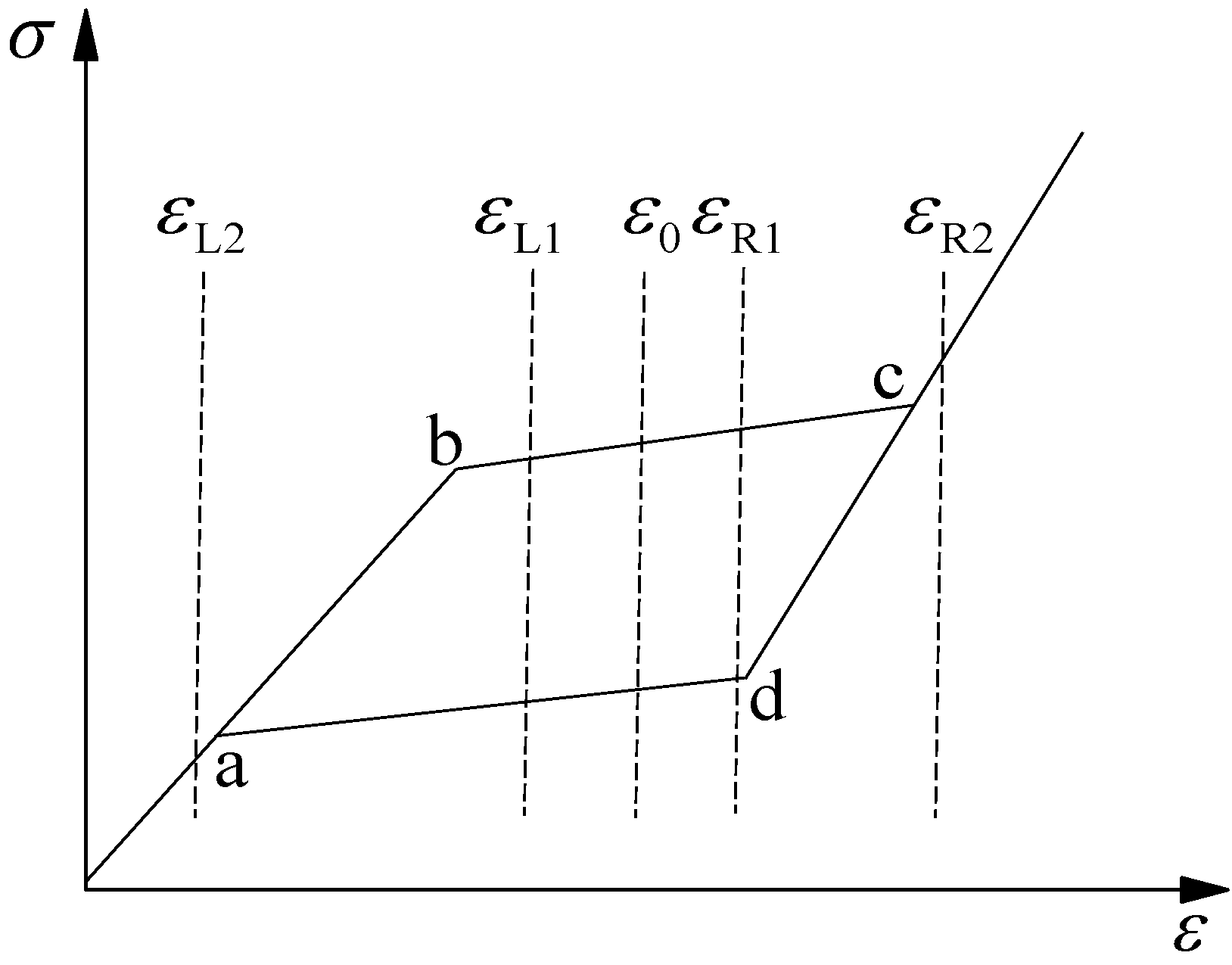
3.1. Hyperelastic Constitutive Model of SMA Wires

The simplified hyperelastic constitutive model for SMA wires suggested by Ou [3] is employed herein this study, as illustrated in Figure 3, where E a represents the austenite (austenitic phase) elastic modulus, E ab denotes the elastic modulus during the austenite-to-martensite phase transformation, E m represents the martensite elastic modulus, and E cd stands for the elastic modulus during the martensite-to-austenite reverse transformation. By conducting experiments to measure the stress and strain values of the SMA wire material at points a, b, c, and d, the stress–strain paths for the SMA wire during the cyclic loading and unloading process can be precisely defined.
Loading path:
σ = E a ε ε ε b E a ε b + E a b ε ε b ε b < ε < ε c
Unloading path:
σ = σ b + E a ε ε b ε c < ε < ε b E a ε a + E cd ε ε a ε a < ε < ε c E a ε ε ε a

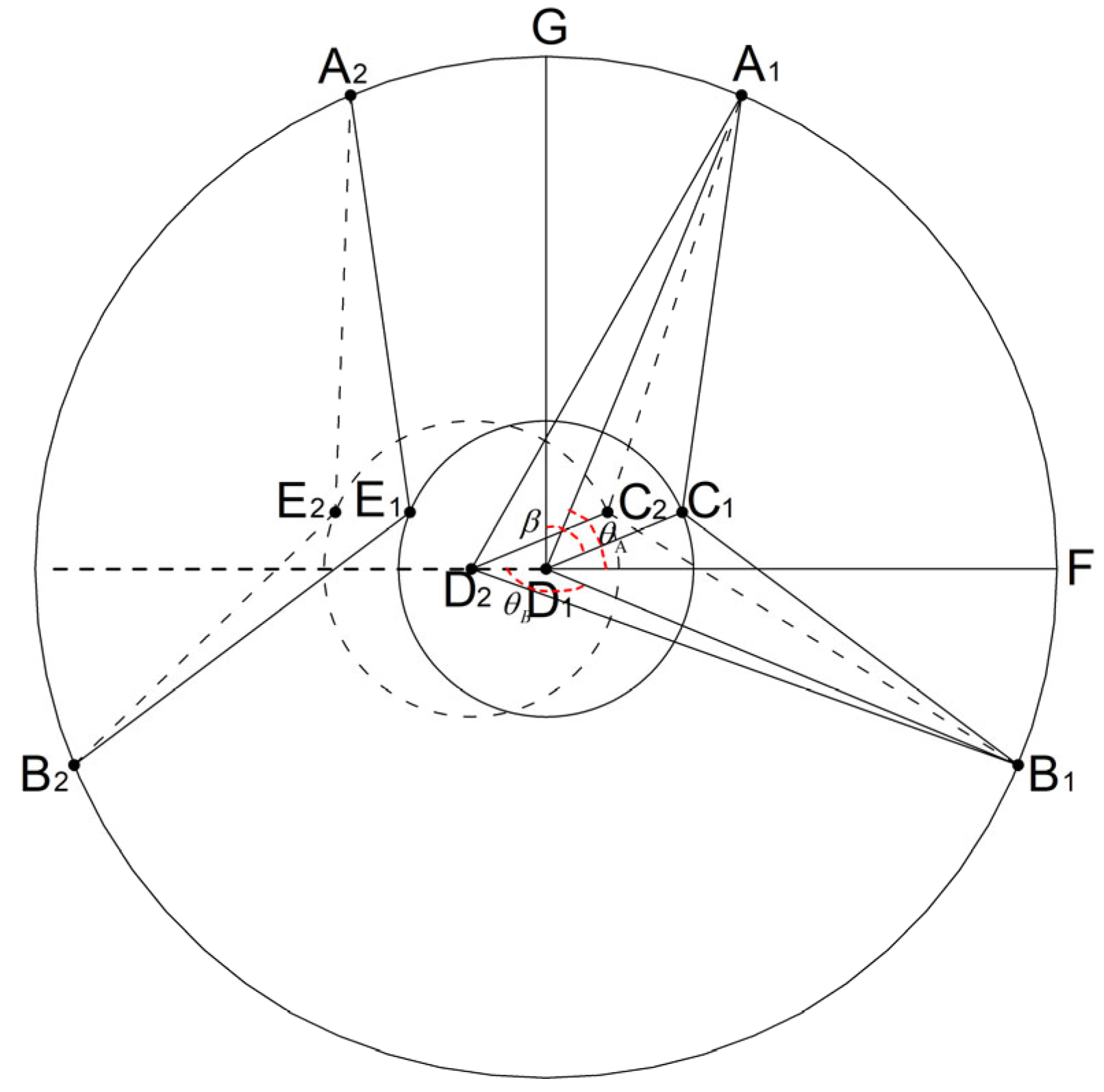
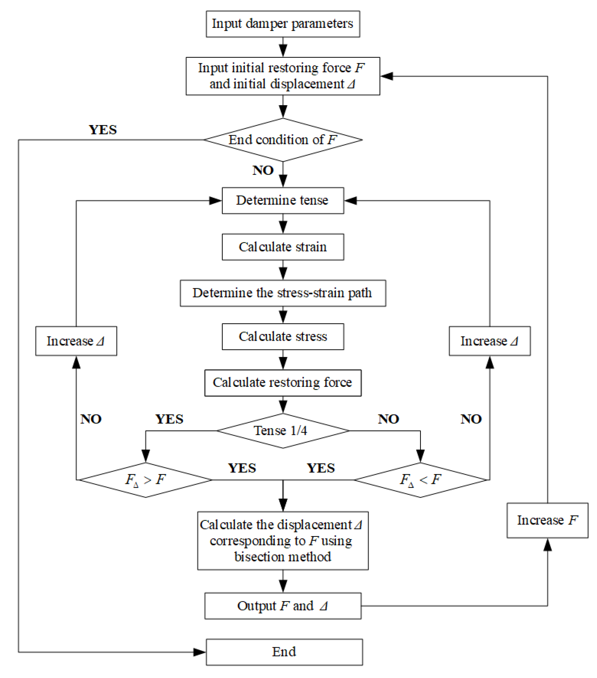
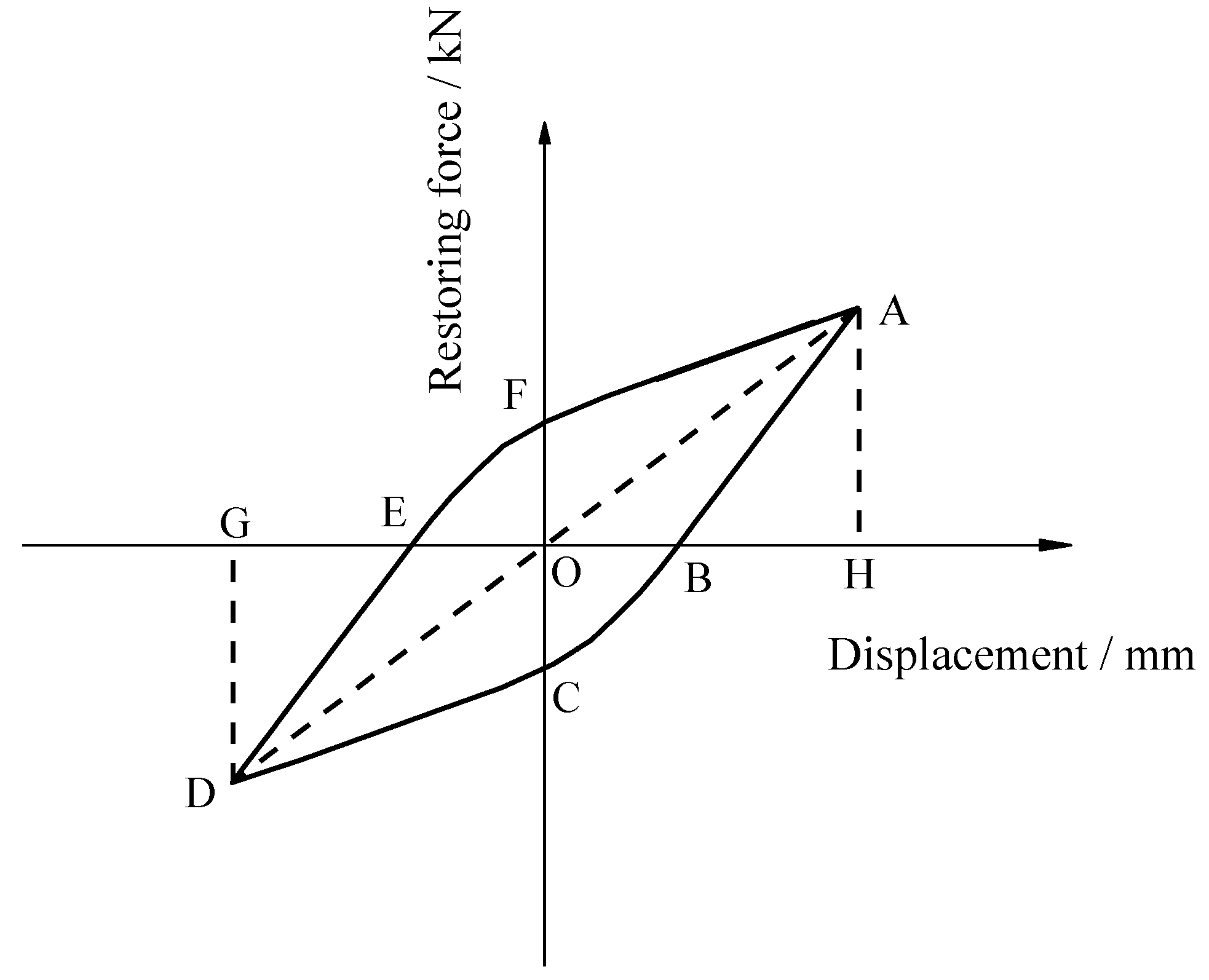
3.2. Restoring Force-Displacement Relationship of the Novel Damper

The restoring force–displacement relationship of the damper is calculated using a layered and grouped superposition approach. The restoring force–displacement relationship for the standard group of SMA wires on the standard layer subjected to cyclic loading is calculated at first. Then, the horizontal force contributions of each group of SMA wires are superimposed based on the included angle of each group of SMA wires. Considering that the layers of the damper are connected in series, the restoring force between any adjacent two layers is equal. After determining the relative displacement between each adjacent layer, the displacements between the layers are summed to obtain the overall relative displacement of the damper. Consequently, the hysteresis curves of the restoring force–displacement relationship for the SMA damper can be obtained.
Figure 4 illustrates the calculation diagram for the restoring force–displacement relationship of the standard group of SMA wires. Taking two symmetric SMA wire groups (A1C1B1 and A2C2B2 in Figure 4) as an example, the solid outer circle in the diagram represents the outer contour of the intermediate plates in the damper. Point D1 is the centroid of the damper. The original length of the SMA wire before pre-tensioning is denoted as L 0 , and the total length of the SMA wire after pre-tensioning L 0 is determined by the following equation,
L 0 = L A 1 C 1 + L B 1 C 1 = 2 R 2 sin 2 π 4 + ( R cos π 4 r ) 2 1 / 2
where R is the radius of the intermediate plates in the damper, and r is the radius of the large circular slider which is composed of 16 sector-shaped small sliders, as shown in Figure 2c. Assuming horizontal displacement occurs between the intermediate plates and the large circular slider, correspondingly, points C1, D1, and E1 are translated to points C2, D2, and E2, as illustrated in Figure 4, and the horizontal displacement Δ can be expressed as
Δ = L C 1 C 2 = L D 1 D 2 = L E 1 E 2
Accordingly, the length of the right SMA wire A1C1B1 increases to L , and the length of the left SMA wire A2E2B2 decreases to L ,
L = L A 1 C 2 + L B 1 C 2
L = L A 2 E 2 + L B 2 E 2
where L A 1 C 2 , L B 1 C 2 , L A 2 E 2 , and L B 2 E 2 are the lengths of A1C2, B1C2, A2E2, and B2E2, respectively, which can be calculated based on the cosine theorem.
L A 1 C 2 = r 2 + Δ 2 + R 2 2 Δ R cos θ A 2 r ( R cos π 4 + Δ cos β ) 1 / 2
L B 1 C 2 = r 2 + Δ 2 + R 2 2 Δ R cos θ B 2 r ( R cos π 4 + Δ cos β ) 1 / 2
L A 2 E 2 = r 2 + Δ 2 + R 2 + 2 Δ R cos θ A 2 r ( R cos π 4 Δ cos β ) 1 / 2
L B 2 E 2 = r 2 + Δ 2 + R 2 + 2 Δ R cos θ B 2 r ( R cos π 4 Δ cos β ) 1 / 2
where θ A represents the angle between line A1D1 and the horizontal line D1F, θ B represents the angle between line B1D1 and the horizontal line D1D2, and β represents the angle between line C1D1 and the vertical line D1G. Obviously, the values of θ A , θ B , and β are related to the arrangement of SMA wires in the damping standard layer. According to the SMA wire arrangement scheme, the values of θ A , θ B , and β are determined by the following equations,
θ A = 3 π 8 + α , 4 π 8 + α , 5 π 8 + α 18 π 8 + α
θ B = 7 π 8 + α , 8 π 8 + α , 9 π 8 + α 22 π 8 + α
β = C 1 D 1 B 1 FD 1 B 1 π 2 = 1 2 θ A + 1 2 θ B 2 α π
where α [ π 16 , + π 16 ] .
Accordingly, the strain values of the SMA wires on the left and right sides can be expressed as
ε R = L 0 L d ε = L 0 L d L L = ln L L 0
ε L = L 0 L d ε = L 0 L d L L = ln L L 0
where ε R and ε L are the real-time strain values of the SMA wires on the right and left side of the symmetric SMA wire group, respectively. Substituting Equations (5)–(10) into Equations (14) and (15) yields
ε R = ln r 2 + Δ 2 + R 2 2 Δ R cos θ A 2 r ( R cos π 4 + Δ cos β ) 1 / 2 + r 2 + Δ 2 + R 2 2 Δ R cos θ B 2 r ( R cos π 4 + Δ cos β ) 1 / 2 ln L 0
ε L = ln r 2 + Δ 2 + R 2 + 2 Δ R cos θ A 2 r ( R cos π 4 Δ cos β ) 1 / 2 + r 2 + Δ 2 + R 2 + 2 Δ R cos θ B 2 r ( R cos π 4 Δ cos β ) 1 / 2   ln L 0
After appling the reciprocating load on the multi-layer self-centring SMA damper, as shown in Figure 5, and to identify the stress and strain paths corresponding to eight groups of sixteen SMA wires based on the SMA’s superelastic stress–strain relationship, the real-time stress of each SMA wire and the real-time restoring force of the damper can be calculated. Taking any pair of symmetric SMA wires as illustrated in Figure 4 as an example, assuming that both SMA wires present the same initial pre-tension strain of ε 0 , when horizontal displacement occurs between the intermediate plate and the circular large slider due to external vibrational loads, the real-time strain value of the left-side SMA and right-side SMA wires may have the following four magnitude relationships with the strain values at points a and c on the SMA stress–strain path, as illustrated in Figure 6: (I) ε R 1 < ε c and ε L 1 > ε a , (II) ε R 2 ε c and ε L 1 > ε a , (III) ε R 1 < ε c and ε L 2 ε a , (IV) ε R 2 > ε c and ε L 2 < ε a , where ε L 1 and ε L 2 are the possible real-time strain value of the left-side SMA, and ε R 1 and ε R 2 are the possible real-time strain value of the right-side SMA. The above four strain magnitude relationships can also be defined as the real-time strain patterns of SMA wires and the above four strain patterns can be obtained by determining whether the SMA wire reaches the martensitic phase after loading from the initial pre-tension state and whether it reaches the austenitic phase after unloading.
In accordance with the direction and magnitude of the horizontal displacement which occurs between the intermediate plate and the circular large slider, the stress–strain paths of the SMA wires under different SMA strain patterns can be further categorized into four tenses. Taking the right-side SMA wire in Figure 4 as an example: tense ① involves stretching from the pre-tension strain point to the furthest point, tense ② involves returning from the furthest point to the original position, tense ③ involves unloading from the pre-tension strain point to the furthest point, tense ④ involves returning from the furthest point to the pre-tension strain point, tense ⑤ represents the tense ① of the second cycle, (6) tense 6 represents the tense ② of the second cycle, tense ⑦ represents the tense ③ of the second cycle, and so forth. The real-time strain of the SMA wires can be determined by the horizontal displacement Δ which occurs between the intermediate plate and the circular large slider, and then the corresponding real-time stress can be obtained in conjunction with the specific stress–strain paths of the SMA wires.
Taking the II-type strain pattern as an example, the strain pattern of the two symmetric SMA wires presented in Figure 4 can be further classified into two subclasses based on the specific stress–strain paths during the loading and unloading process, as shown in Figure 7, where the auxiliary points in Figure 7 are defined as follows: point e is the intersection of the line x = ε 0 and line ad, point f is the intersection of the line x = ε R 2 and line cd, point h is the intersection of the line x = ε L 1 and line ad, point i is the intersection of the line through point h with a slope of K1 and the line x = ε 0 , point k is the intersection of the line hi and the line bc, point g is the intersection of the line through point p with a slope of K1 and line ad, and point j is the intersection of the line pg and line x = ε L 1 . Consequently, the real-time strain of each SMA wire can be determined by Equations (16) and (17), and the corresponding real-time stress of each SMA wire can be determined through a more detailed subdivision of the strain patterns and tense characteristics.
According to the above-mentioned method, the stress and strain values of each SMA wire corresponding to any given incremental displacement Δ can be calculated. In accordance with the principle of constant volume for SMA wire, the real-time cross-sectional area of the SMA wires which are undergoing an increase in strain and those experiencing a decrease in strain, as shown in Figure 4, can be expressed as A R and A L , respectively.
A R = A 0 L 0 / L = A 0 L 0 / r 2 + Δ 2 + R 2 2 Δ R cos θ A 2 r ( R cos π 4 + Δ cos β ) 1 / 2 + r 2 + Δ 2 + R 2 2 Δ R cos θ B 2 r ( R cos π 4 + Δ cos β ) 1 / 2
A L = A 0 L 0 / L = A 0 L 0 / r 2 + Δ 2 + R 2 + 2 Δ R cos θ A 2 r ( R cos π 4 Δ cos β ) 1 / 2 + r 2 + Δ 2 + R 2 + 2 Δ R cos θ B 2 r ( R cos π 4 Δ cos β ) 1 / 2
Correspondingly, the real-time tensile forces of the SMA wires with increased strain and the SMA wires with decreased strain can be calculated and expressed as F R and F L , respectively.
F R = A R σ R
F L = A L σ L
Then, the resultant force F i for the symmetric pairs of SMA wires in the direction of the damper’s horizontal displacement can be given,
F i = F R cos γ R 1 + F R cos γ R 2 + F L cos γ L 1 + F L cos γ L 2
where γ R 1 and γ R 2 are the intersection angles between the SMA wires with increased strain and the horizontal direction, γ L 1 and γ L 2 are the intersection angles between the SMA wires with decreased strain and the horizontal direction, and γ R 1 , γ R 2 , γ L 1 , and γ L 2 can be calculated based on the cosine theorem.
cos γ R 1 = 2 Δ 2 2 Δ R cos θ A 2 Δ r cos β 2 Δ r 2 + Δ 2 + R 2 2 Δ R cos θ A 2 r ( R cos π 4 + Δ cos β ) 1 / 2
cos γ R 2 = 2 Δ 2 2 Δ R cos θ B 2 r Δ cos β 2 Δ r 2 + Δ 2 + R 2 2 Δ R cos θ B 2 r ( R cos π 4 + Δ cos β ) 1 / 2
cos γ L 1 = 2 Δ 2 + 2 Δ R cos θ A + 2 Δ r cos β 2 Δ r 2 + Δ 2 + R 2 + 2 Δ R cos θ A 2 r ( R cos π 4 Δ cos β ) 1 / 2
cos γ L 2 = 2 Δ 2 + 2 Δ R cos θ B + 2 Δ r cos β 2 Δ r 2 + Δ 2 + R 2 + 2 Δ R cos θ B 2 r ( R cos π 4 Δ cos β ) 1 / 2
Accordingly, the restoring force for any layer of SMA wires in the direction of horizontal displacement can be obtained by combining the forces from each group of SMA wires. Due to the symmetric arrangement of SMA wires, the total restoring force in the direction perpendicular to the incremental displacement is always zero. Using the above calculation method, the restoring force–displacement curve for each layer of the damper can be computed. By summing up the incremental displacements calculated for each layer, the overall restoring force–displacement hysteresis curve for the damper can be obtained. The aforementioned calculation process has been implemented into a computer program using MATLAB R2020a, as illustrated in Figure 8. By inputting relevant design parameters of the damper into the program, the corresponding restoring force–displacement hysteresis curve can be obtained.

4. Parameter Analysis

In accordance with the engineering technical requirements of a highly flexible structure vibration control project, a novel multi-layer self-centring SMA damper was developed. The design parameters of the damper were as follows: the radius of the intermediate plate is R = 260 mm, and the radius of the circular large slider is r = 75 mm. NiTi shape memory alloy wires produced by Northwest Nonferrous Metal Research Institute were employed, and the austenite elastic modulus and martensite elastic modulus were measured to be 80 GPa and 25 GPa, respectively. The starting and ending stresses for the stress-induced martensitic transformation were 500 MPa and 700 MPa, respectively. The starting and ending stresses for the stress-induced martensitic reverse transformation were 200 MPa and 100 Mpa, respectively. The force-controlled loading mode, as illustrated in Figure 5, was utilized to apply reciprocating loads to the SMA damper. In this section, the effect of SMA pre-strain, SMA diameter, number of layers in the damper, and number of SMA wires per layer on the hysteresis performance of the damper were investigated, on the basis of the previously established damper restoring force–displacement hysteresis calculation model.

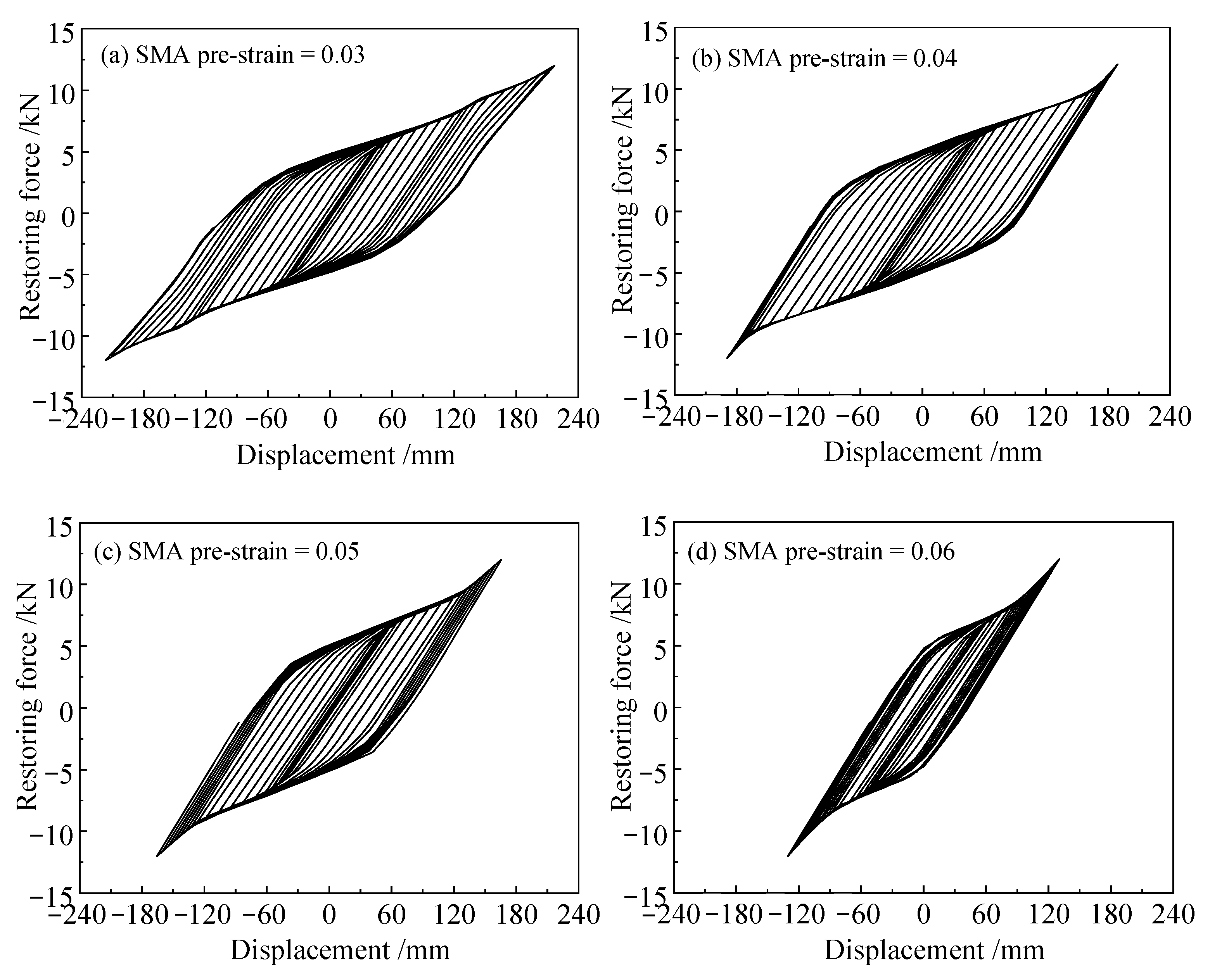
4.1. Effect of SMA Pre-Strain

An SMA wire diameter of 2 mm, a damper composed of 10 layers, and 16 symmetrically arranged SMA wires in each layer serve as the fundamental parameters to investigate the effect of SMA pre-strain on the hysteresis performance of the damper. Figure 9a–d presents the damper’s restoring force–displacement hysteretic curves corresponding to SMA pre-strains of 0.03, 0.04, 0.05, and 0.06, respectively. As shown in Figure 9, all hysteretic curves exhibit a full spindle shape, indicating that the damper possesses excellent energy dissipation capabilities. Additionally, it is noteworthy that when the displacement amplitude is small, the damper exhibits relatively high stiffness, suggesting a substantial initial stiffness. This implies that using this damper for base isolation in structures can prevent frequent oscillations during normal usage phases. As the displacement amplitude increases, the damper enters a yielding platform, resulting in a significant reduction in isolation stiffness. This effectively hinders the upward transmission of vibrational energy from the base to the upper structure. When further increasing the displacement amplitude until the maximum stroke, the damper stiffness suddenly increases, indicating a considerable limit stiffness. This characteristic helps prevent excessive lateral displacement in the isolation layer, thus avoiding the overturning of the upper structure. It can also be observed from Figure 9 that the SMA pre-strain significantly alters the characteristics of the damper’s restoring force–displacement hysteretic curves. As the SMA pre-strain increases continuously, the hysteresis loop consistently narrows, and the maximum stroke of the damper (i.e., the displacement amplitude of the damper entering the limit stiffness stage) decreases progressively.
Figure 10a–c depict the influence of SMA pre-strain on the damper’s stiffness, unit cycle energy dissipation, and equivalent viscous damping ratio, respectively, where the damper’s stiffness refers to the slope of the restoring force–displacement curve. The unit cycle energy dissipation represents the area enclosed by the hysteresis loop corresponding to any complete load cycle, as illustrated in Figure 10, and can be computed through the integration of the hysteresis curve. The equivalent viscous damping ratio can be calculated using the following formula:
ξ = 1 2 π S ABCDEF S Δ AOH + S Δ DOG
where ξ is the equivalent viscous damping ratio, S ABCDEF is the area enclosed by the hysteresis loop ABCDEF, i.e., the unit cycle energy dissipation, and S Δ AOH and S Δ DOG are the areas enclosed by the triangles AOH and DOG, respectively, as shown in Figure 11.
It can be observed from Figure 10a that the influence of SMA pre-strain on the initial stiffness and isolation stiffness of the damper is not significant. However, there is a certain impact on the limit stiffness of the damper, which shows an increasing trend as the pre-strain increases. Figure 10b indicates that for small displacement amplitudes, the difference in unit cycle energy dissipation for different SMA pre-strains is not pronounced. However, as the displacement amplitude increases, the gap in unit cycle energy dissipation becomes more evident for various SMA pre-strains. It is also noticeable that, at the same displacement amplitude, as the SMA pre-strain increases from 0.03 to 0.04, 0.05, and 0.06, the unit cycle energy dissipation of the damper initially increases and then decreases, with the best energy dissipation achieved at a pre-strain of 0.04. Figure 10c reveals that the equivalent damping ratio of the damper shows an increasing trend, followed by a decreasing trend as the displacement amplitude increases. As for small displacement amplitudes, the damper’s equivalent damping ratio is maximum at an SMA pre-strain of 0.03, and the differences between equivalent damping ratios for different SMA pre-strains are relatively small. As the displacement amplitude gradually increases, the equivalent damping ratio corresponds to the SMA pre-strain of 0.04, surpassing that at the pre-strain of 0.03, and reaching its maximum value. Additionally, the differences in equivalent damping ratios for different SMA pre-strains increase progressively.

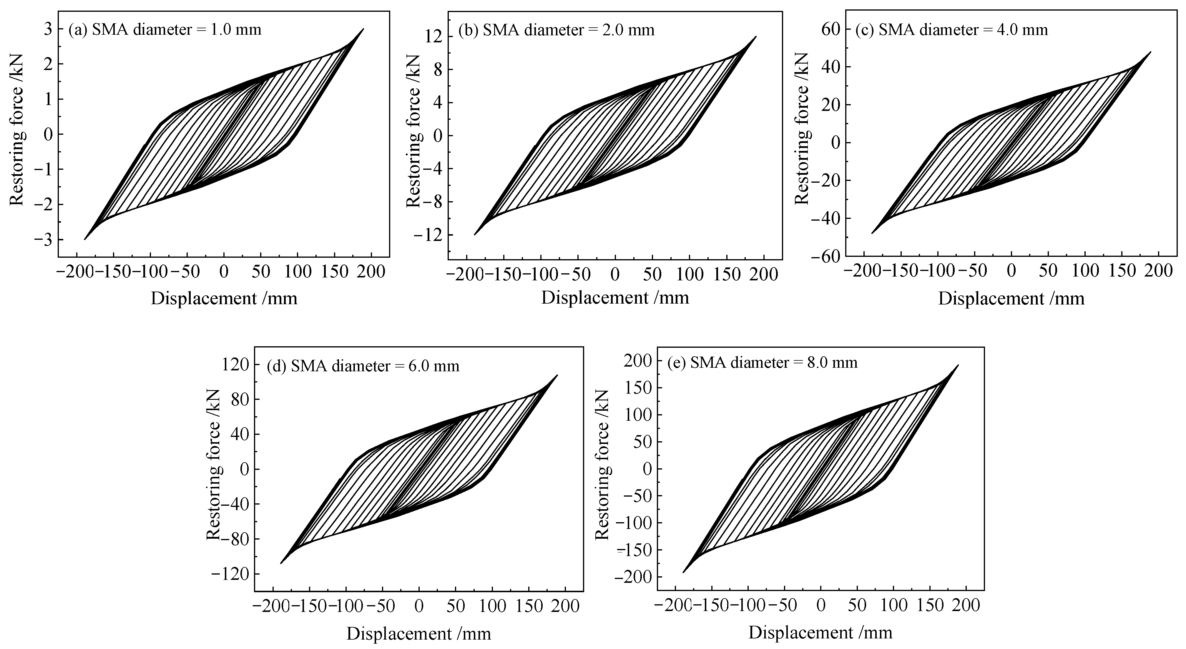
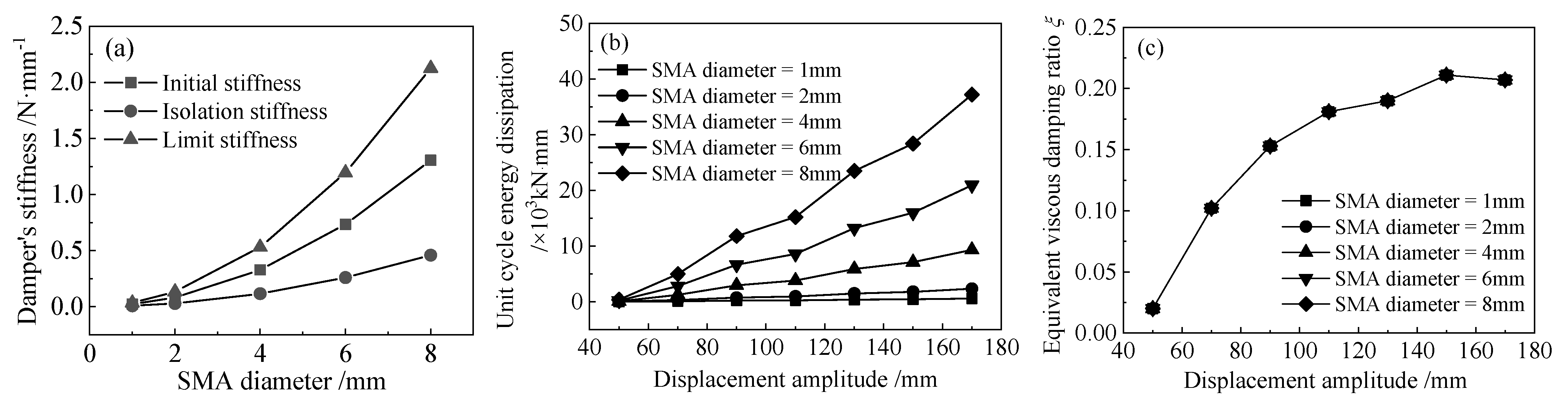
4.2. Effect of SMA Diameter

An SMA pre-strain of 0.04, a damper composed of 10 layers, and 16 symmetrically arranged SMA wires in each layer serve as the fundamental parameters to investigate the effect of SMA diameter on the hysteresis performance of the damper. Figure 12a–e presents the damper’s restoring force–displacement hysteretic curves corresponding to SMA diameters of 1 mm, 2 mm, 4 mm, 6 mm, and 8 mm, respectively. As shown in Figure 12, for the same displacement amplitude, the restoring force increases continuously with the increase in SMA diameter, indicating an increasing stiffness of the damper. It is also noticeable that the SMA diameter has minimal impact on the maximum stroke of the damper.
Figure 13a–c illustrate the effect of SMA diameter on the damper’s stiffness, unit cycle energy dissipation, and equivalent viscous damping ratio, respectively. As illustrated in Figure 13a, as the SMA diameter increases, the initial stiffness, isolation stiffness, limit stiffness, and the differences between them increase continuously. This is mainly due to the fact that the damper stiffness is directly proportional to the square of the SMA diameter. Figure 13b reveals that with the continuous increase in SMA diameter, the unit cycle energy dissipation for the damper at the same displacement amplitude steadily increases, and the differences in unit cycle energy dissipation between different SMA diameters also become more pronounced. Figure 13c shows that the equivalent viscous damping ratio of the damper exhibits an increasing trend followed by stabilization as the displacement amplitude increases, whereas the variation in SMA diameter does not have a significant impact on the equivalent viscous damping ratio of the damper.

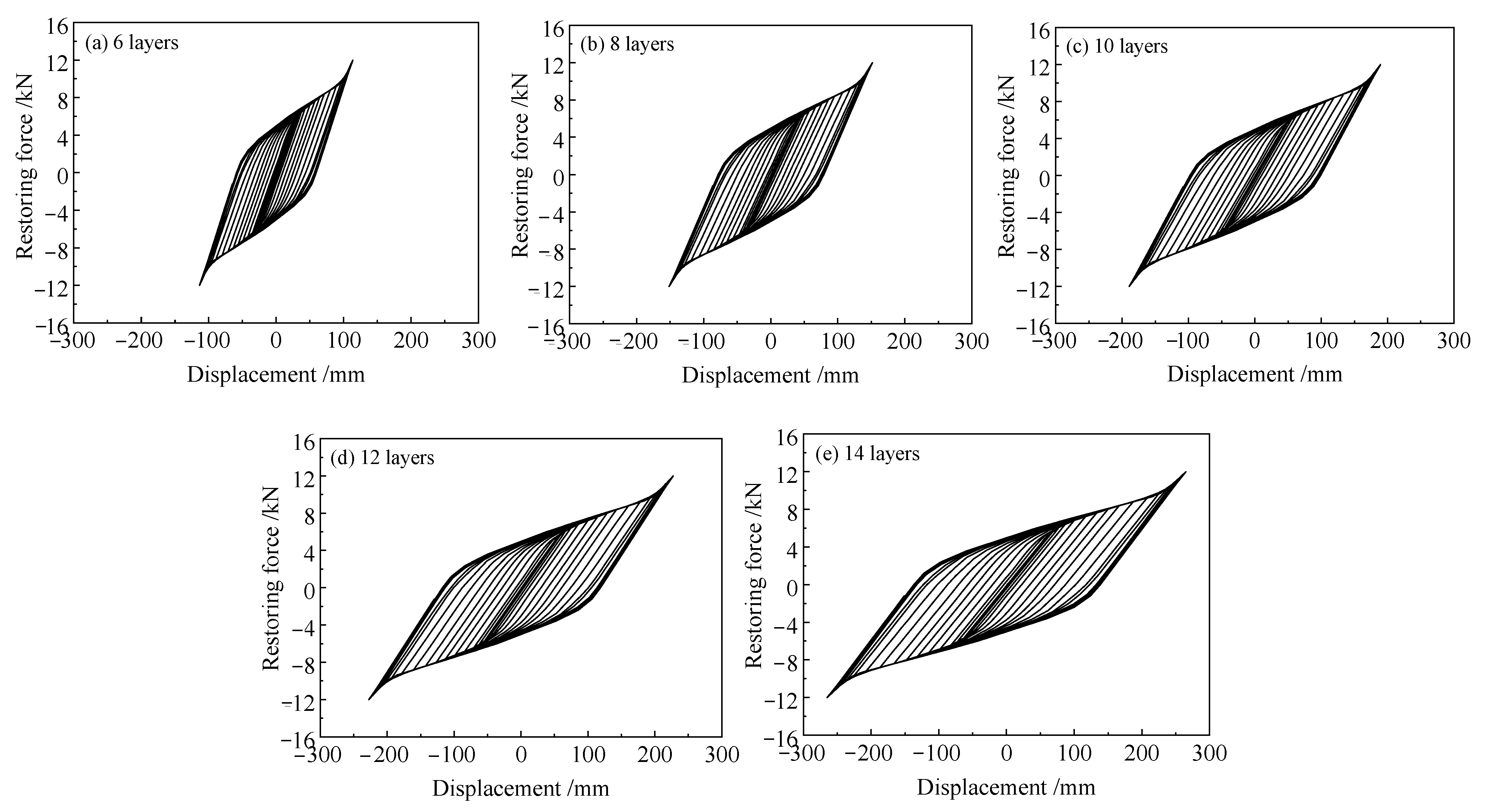
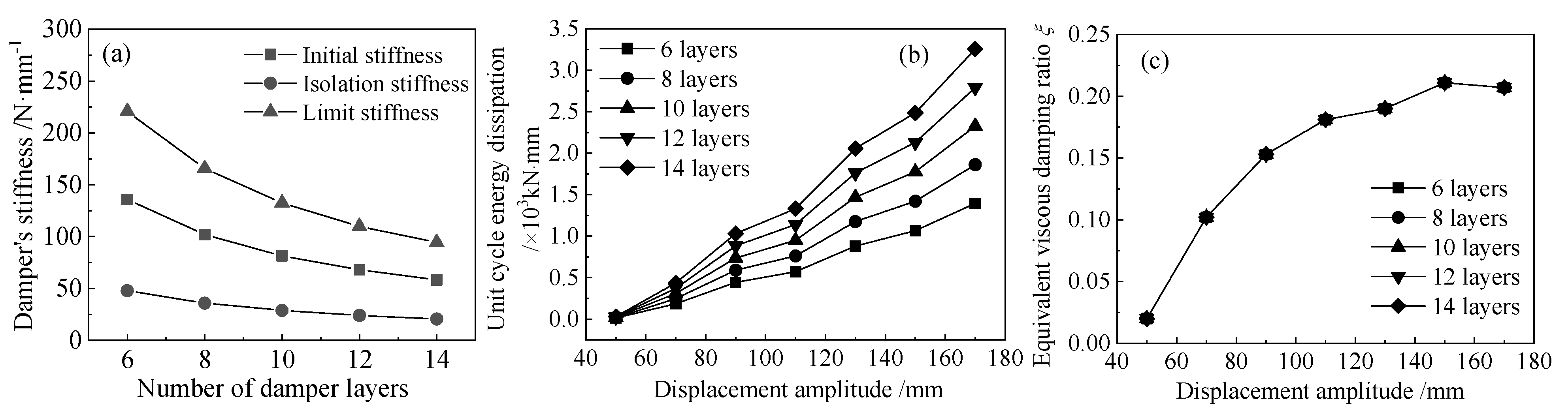
4.3. Effect of the Number of Damper Layers

With a pre-strain of the SMA wires set to 0.04, the diameter of SMA chosen as 2 mm, and 16 symmetrically arranged SMA wires in each layer, these parameters serve as the fundamental parameters to investigate the effect of the number of damper layers on the hysteresis performance of the damper. Figure 14a–e presents the damper’s restoring force–displacement hysteretic curves corresponding to damper layers of 6, 8, 10, 12, and 14, respectively. It can be observed from Figure 14 that as the number of layers increases, the damper stroke significantly increases, whereas the stiffness continuously decreases.
Figure 15a–c depict the influence of the number of damper layers on the damper’s stiffness, unit cyclic energy dissipation, and equivalent viscous damping ratio, respectively. As depicted in Figure 15a, with an increasing number of damper layers, the initial stiffness, isolation stiffness, and limit stiffness of the damper continuously decrease. This is attributed to the serial arrangement of damper layers, where the restoring force between adjacent layers is the same; the total displacement of the damper is directly proportional to the number of damper layers, leading to an inverse relationship between the damper’s stiffness and the number of damper layers. As shown in Figure 15b, a greater number of damper layers results in larger unit cyclic energy dissipation for the same displacement amplitude; additionally, unit cyclic energy dissipation is directly proportional to the number of damper layers. This phenomenon is due to the reduction in damper stiffness and the increase in displacement with an increasing number of layers, resulting in a larger area enclosed by the restoring force–displacement hysteresis loop and, consequently, an increase in unit cyclic energy dissipation. Figure 15c indicates that the number of damper layers has no impact on the equivalent viscous damping ratio of the damper.

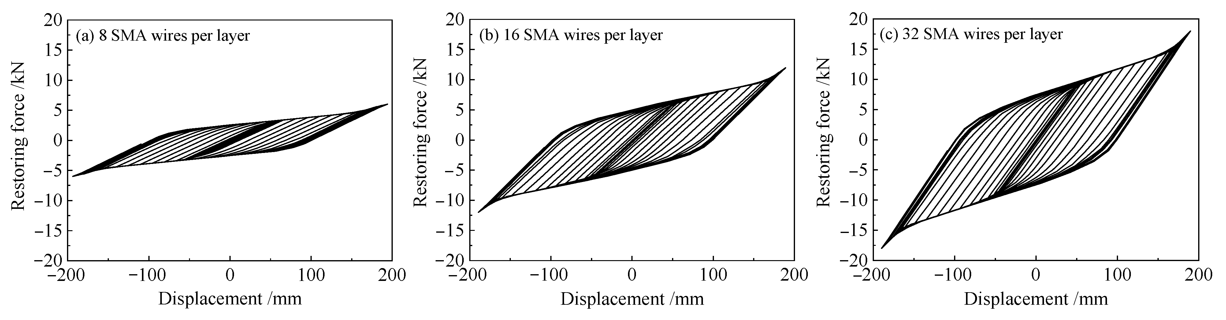
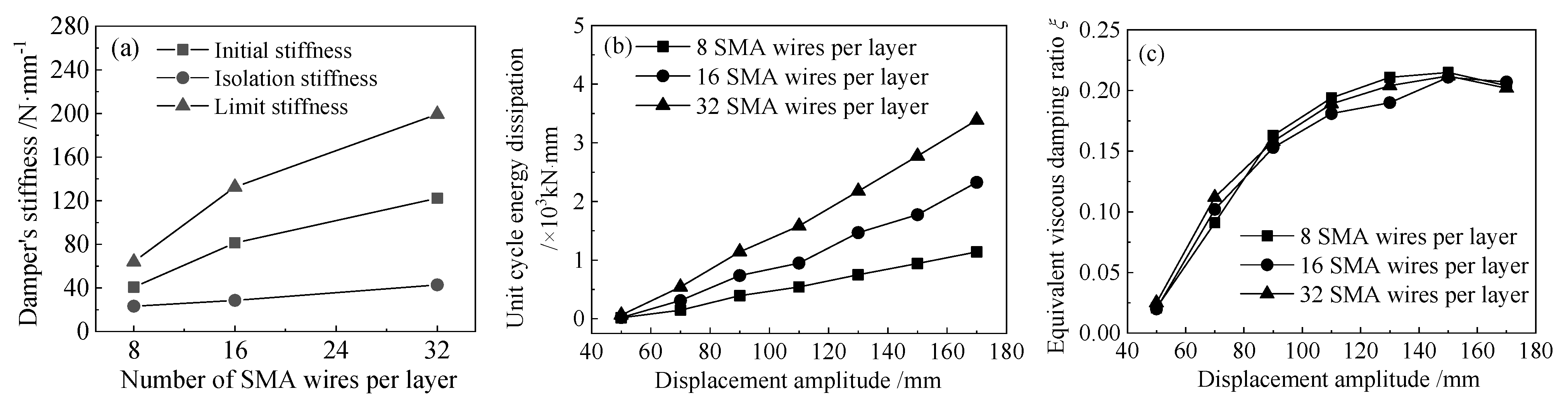
4.4. Effect of the Number of SMA Wires per Layer

With the pre-strain of SMA wires set to 0.04, the diameter of SMA chosen as 2 mm, and the damper composed of 10 layers, these parameters serve as the fundamental parameters to investigate the effect of the number of SMA wires per layer on the hysteresis performance of the damper. Figure 16 presents the restoring force–displacement hysteresis curves corresponding to different numbers of SMA wires per layer, namely 8, 16, and 32. It can be observed from Figure 16 that as the number of SMA wires per layer gradually increases, there is no significant change in the damper stroke; however, the damper’s stiffness and the area enclosed by the force–displacement hysteresis loop for the same displacement amplitude continuously increase.
Figure 17a–c illustrate the influence of the number of SMA wires per layer on the damper’s stiffness, unit cyclic energy dissipation, and equivalent viscous damping ratio, respectively. As illustrated in Figure 17, an increase in the number of SMA wires per layer leads to higher damper stiffness and greater unit cyclic energy dissipation; the equivalent damping ratio shows an increasing trend followed by a decreasing trend as the displacement amplitude increases, while the differences between the equivalent damping ratios for different numbers of SMA wires per layer are relatively small. To interpret this phenomenon, the equivalent viscous damping ratio mainly reflects the shape characteristics of the damper hysteresis loop from a mechanistic perspective, as shown in Figure 11. Combining the patterns shown in Figure 10c, Figure 13c, Figure 15c and Figure 17c, it can be found that the shape characteristics of the hysteresis loop may mainly be related to the SMA pre-strain but not to the number of SMA wires (regardless of the number of damper layers or the number of SMA wires per layer) and SMA diameter.

5. Conclusions

This paper proposed a novel multi-layer self-centring SMA damper and introduced the basic structure design and operational principles. A model for calculating the restoring force–displacement hysteretic curve of the damper was established, and based on this theoretical model, a parameter analysis of the damper’s hysteresis performance was conducted. The effects of SMA pre-strain, SMA diameter, number of layers in the damper, and number of SMA wires per layer on the damper’s stiffness, the unit cycle energy dissipation, and the equivalent viscous damping ratio were investigated, respectively. The main conclusions are as follows:
(1)
The restoring force–displacement hysteretic curve of the novel SMA damper exhibits a full spindle shape. The damper possesses good energy dissipation capability, self-recovery function, significant stroke, and unique variable stiffness characteristics (i.e., appropriate initial stiffness, minimal isolation stiffness, and significant limit stiffness). The established damper restoring force–displacement hysteresis calculation model accurately predicts the damper’s hysteresis behavior.
(2)
The results of the parameter analysis indicate that the SMA pre-strain has a minor impact on the damper’s stiffness but a significant influence on unit cyclic energy dissipation and equivalent damping ratio. As the SMA pre-strain increases, the maximum stroke of the damper continuously decreases, while the unit cyclic energy dissipation initially increases and then decreases, with the optimal energy dissipation achieved at a pre-strain of 0.04. As the SMA diameter increases, both the damper’s stiffness and unit cyclic energy dissipation increase, while the maximum stroke and equivalent damping ratio remain unchanged. With an increasing number of damper layers, the maximum stroke and unit cyclic energy dissipation continuously increase, whereas the stiffness decreases and the equivalent damping ratio remains constant. As the number of SMA wires per layer increases from 8 to 16 and 32, the maximum stroke and equivalent damping ratio present little variation, but the damper’s stiffness and unit cyclic energy dissipation continuously increase.

6. Patents

The following patent is derived from the findings of the work reported in this manuscript: A novel multi-layer self-centering damper utilizing shape memory alloy and its installation method. Chinese Patent: ZL2018 1 1319914.9, 2020.

Author Contributions

Conceptualization, A.L. and S.X.; methodology, H.Z.; software, H.Z.; validation, H.Z., L.Z. and A.L.; formal analysis, H.Z.; investigation, H.Z. and A.L.; resources, A.L. and S.X.; data curation, H.Z. and L.Z.; writing—original draft preparation, all authors; writing—review and editing, A.L.; visualization, A.L.; supervision, A.L. and S.X.; project administration, A.L. and S.X.; funding acquisition, H.Z., A.L. and S.X. All authors have read and agreed to the published version of the manuscript.

Funding

This research was funded by the National Natural Science Foundation of China (No. 52078402), and Shaanxi Provincial Key Research and Development Program (No. 2022SF-467).

Data Availability Statement

All data are shown in the paper.

Conflicts of Interest

Author Lu Zhao was employed by the company XAUAT Engineering Technology Co., Ltd. Author Hua Zhang was employed by the company China Coal Xi’an Design Engineering Co., Ltd. The remaining authors declare that the research was conducted in the absence of any commercial or financial relationships that could be construed as a potential conflict of interest.

References

  1. Monjardin-Quevedo, J.G.; Valenzuela-Beltran, F.; Reyes-Salazar, A.; Leal-Graciano, J.M.; Torres-Carrillo, X.G.; Gaxiola-Camacho, J.R. Probabilistic Assessment of Buildings Subjected to Multi-Level Earthquake Loading Based on the PBSD Concept. Buildings 2022, 12, 20. [Google Scholar] [CrossRef]
  2. Jia, H.; Lin, J.; Liu, J. Review of Seismic Fragility Analysis of Building Structure. Technol. Earthq. Disaster Prev. 2019, 14, 42–51. [Google Scholar]
  3. Ping, O.J. Structural Vibration Control Active, Semi-Active and Intelligent Control; Science Press: Beijin, China, 2003. [Google Scholar]
  4. Zhou, Y.; Wu, H.; Gu, A.Q. Earthquake engineering: From earthquake resistance, energy dissipation, and isolation, to resilience. Eng. Mech. 2019, 36, 1–12. [Google Scholar]
  5. Clemente, P. Seismic isolation: Past, present and the importance of SHM for the future. J. Civ. Struct. Health Monit. 2017, 7, 217–231. [Google Scholar] [CrossRef]
  6. Yu, L.; Chen, K.; Zhang, Y.; Liu, J.; Yang, L.; Shi, Y. Microstructures and mechanical properties of NiTi shape memory alloys fabricated by wire arc additive manufacturing. J. Alloys Compd. 2022, 892, 162193. [Google Scholar] [CrossRef]
  7. Mccormick, J.; Desroches, R. Effect of Mechanical Training on the Properties of Superelastic Shape Memory Alloys for Seismic Applications. In Smart Structures and Materials 2005: Smart Structures and Integrated Systems, Proceedings of the SPIE Smart Structures and Materials + Nondestructive Evaluation and Health Monitoring, San Diego, CA, USA, 7–10 March 2005; The International Society for Optical Engineering (SPIE): San Diego, CA, USA, 2005; Volume 5764. [Google Scholar]
  8. Jani, J.M.; Leary, M.; Subic, A.; Gibson, M.A. A review of shape memory alloy research, applications and opportunities. Mater. Des. 2014, 56, 1078–1113. [Google Scholar] [CrossRef]
  9. Li, H.; Mao, C.X.; Ou, J.P. Experimental and theoretical study on two types of shape memory alloy devices. Earthq. Eng. Struct. Dyn. 2008, 37, 407–426. [Google Scholar] [CrossRef]
  10. Yu, Q.C.; Liu, C.H.; Liu, A.R. The analysis of structure vibration control by using shape memory alloy dampers with magnifying story drift. J. Earthq. Eng. Eng. Vib. 2008, 2008, 151–156. [Google Scholar]
  11. Chen, Y.; Lv, X.L.; Jiang, H.J. Seismic performance study on new enhanced energy dissipation SMA damper. J. Hunan Univ. (Nat. Sci.) 2013, 40, 31–38. [Google Scholar]
  12. Huang, Z.; Li, H.N.; Fu, X. Optimum design of a re-centering deformation-amplified SMA damper. Eng. Mech. 2019, 36, 202–210. [Google Scholar]
  13. Parulekar, Y.M.; Reddy, G.R.; Vaze, K.K.; Guha, S.; Gupta, C.; Sreekala, K.M. Seismic response attenuation of structures using shape memory alloy dampers. Struct. Control Health Monit. 2012, 19, 102–119. [Google Scholar] [CrossRef]
  14. Li, H.N.; Qian, H.; Song, G.B.; Gao, D.W. A type of shape memory alloy damper: Design, experiment and numerical simulation. J. Vib. Eng. 2008, 21, 179–184. [Google Scholar]
  15. Li, H.N.; Huang, Z.; Fu, X.; Li, G. A re-centering deformation-amplified shape memory alloy damper for mitigating seismic response of building structures. Struct. Control Health Monit. 2018, 25, e2233.1–e2233.20. [Google Scholar] [CrossRef]
  16. Xue, S.D.; Shi, G.L.; Zhuang, P. Performance testing of SMA incorporated friction dampers. J. Earthq. Eng. Eng. Vib. 2007, 27, 145–151. [Google Scholar]
  17. Ren, W.J.; Wang, L.Q.; Zhicheng, M.A.; Yao, H.Z. Investigation on mechanical behavior of innovative shape memory alloy-friction damper. J. Build. Struct. 2013, 34, 83–90. [Google Scholar]
  18. Qian, H.; Li, H.; Song, G. Experimental investigations of building structure with a superelastic shape memory alloy friction damper subject to seismic loads. Smart Mater. Struct. 2016, 25, 125026. [Google Scholar] [CrossRef]
  19. Sun, T.; Li, H.N. Experimental investigation of an innovative multidimensional SMA damper. Eng. Mech. 2018, 35, 178–185. [Google Scholar]
  20. Qiu, C.X.; Liu, J.W.; Du, X.L. Numerical simulation and parametric study of shape memory alloy slip friction dampers. Eng. Mech. 2021, 39, 69–79. [Google Scholar] [CrossRef]
  21. Wang, W.; Fang, C.; Zhang, A.; Liu, X.S. Manufacturing and performance of a novel self-centring damper with shape memory alloy ring springs for seismic resilience. Struct. Control Health Monit. 2019, 26, e2337. [Google Scholar] [CrossRef]
Figure 1. Three-dimensional conceptual illustration of the multi-layer self-centering SMA damper.
Buildings 14 00483 g001
Figure 2. Orthographic and sectional illustration of the multi-layer self-centering SMA damper: (a) orthographic view; (b) A-A sectional illustration; (c) B-B sectional illustration; (d) C-C sectional illustration; (e) D-D sectional illustration.
Buildings 14 00483 g002
Figure 3. The simplified hyperelastic constitutive model for SMA wires.
Buildings 14 00483 g003
Figure 4. Calculation diagram for the restoring force–displacement relationship of the standard group of SMA wires.
Buildings 14 00483 g004
Figure 5. The reciprocating load applied to the damper.
Buildings 14 00483 g005
Figure 6. Strain patterns determination of the SMA wires.
Buildings 14 00483 g006
Figure 7. Two subclasses of II-type strain pattern of SMA wires: (a) first subclass; (b) second subclass.
Buildings 14 00483 g007
Figure 8. Program chart for calculating the restoring force–displacement hysteresis of the damper.
Buildings 14 00483 g008
Figure 9. The damper’s restoring force–displacement hysteretic curves corresponding to different SMA pre-strains.
Buildings 14 00483 g009
Figure 10. The influence of SMA pre-strain on (a) the damper’s stiffness, (b) the unit cycle energy dissipation, and (c) the equivalent viscous damping ratio.
Buildings 14 00483 g010
Figure 11. Equivalent viscous damping ratio calculation schematic diagram.
Buildings 14 00483 g011
Figure 12. The damper’s restoring force–displacement hysteretic curves corresponding to different SMA diameters.
Buildings 14 00483 g012
Figure 13. Effect of SMA diameter on (a) the damper’s stiffness, (b) the unit cycle energy dissipation, and (c) the equivalent viscous damping ratio.
Buildings 14 00483 g013
Figure 14. The damper’s restoring force–displacement hysteretic curves corresponding to different numbers of damper layers.
Buildings 14 00483 g014
Figure 15. Effect of the number of damper layers on (a) the damper’s stiffness, (b) the unit cycle energy dissipation, and (c) the equivalent viscous damping ratio.
Buildings 14 00483 g015
Figure 16. The damper’s restoring force–displacement hysteretic curves corresponding to different numbers of SMA wires per layer.
Buildings 14 00483 g016
Figure 17. Effect of the number of SMA wires per layer on (a) the damper’s stiffness, (b) the unit cycle energy dissipation, and (c) the equivalent viscous damping ratio.
Buildings 14 00483 g017
Disclaimer/Publisher’s Note: The statements, opinions and data contained in all publications are solely those of the individual author(s) and contributor(s) and not of MDPI and/or the editor(s). MDPI and/or the editor(s) disclaim responsibility for any injury to people or property resulting from any ideas, methods, instructions or products referred to in the content.

