1. Introduction
The purpose of this study is to investigate the seismic behavior of reinforced concrete frame structures that have been extended vertically with additional floors at some point during their service life, specifically focusing on the joints by which the extension is connected to the existing structure and how to appropriately model the joints when checking the load-carrying capacity and serviceability of the entire extended structure.
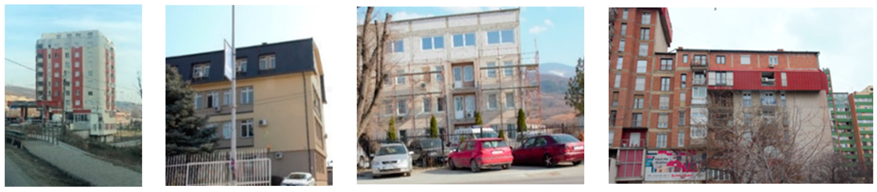
The motivation for this study arose from observing construction trends in the Republic of Kosovo. Economic developments and population growth have resulted in an increase in the need for residential space [
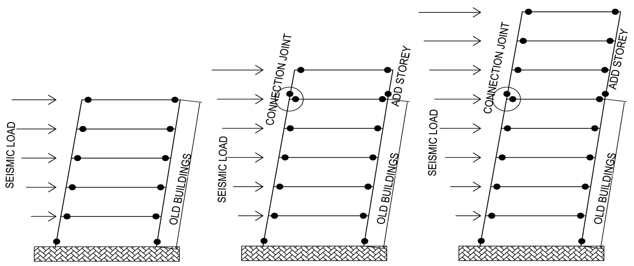
1]. In some cases, this is achieved by adding new floors on top of existing structures. Several cases of this practice are illustrated in
Figure 1. Such vertical or upward extensions need to be carefully planned, designed, and checked to ensure a safe structure. The problem is further compounded, as there are illegal buildings with no building permits issued [
2], and the region is highly seismically active [
3]. Cases in which vertical extensions are made on top of old buildings that were not designed according to the principles and rules of modern (seismic) codes or to sustain the loads prescribed in these modern codes, and that also may have deteriorated over their service life, may be dangerous and require careful examination [
4].
At the same time, there are many benefits to the vertical extension of buildings, and there seems to be an ongoing trend calling for an increase in this approach [
5,
6]. The major advantage is related to the potential for attaining more sustainable solutions, not only for single buildings but on a city scale. Vertical extension avoids the consumption of new land and city sprawl, thus preserving natural habitats, green areas, and agricultural land. An alternative to vertical extension is to demolish the existing building and build a new, taller structure. Building demolition is associated with financial costs, environmental pollution in terms of the emission of carbon dioxide, and the creation of waste, which requires extra management and brings additional costs. It also creates problems for the residents who live there in terms of moving out and paying rent for some other residence until the new building is constructed in place of the old one. Improving existing structures also consumes fewer resources than tearing down and rebuilding, making it more environmentally friendly [
7].
These are all great advantages and arguments for vertical extensions, but at the same time, it is essential to secure the structural safety of these extensions. This study focuses on structural behavior under seismic action, investigating how to appropriately design and model joints between new floors and the existing building. If a vertical extension is not designed and executed properly, the vulnerability and seismic risk increase as the danger of the building collapsing increases. Often, the connection between an existing reinforced structure and the vertical extension is considered rigid in structural analyses, just as if the building had been erected in its entirety at the beginning. In practice, these joints may not behave as such. The floor slabs, which are rigid and flexible, play a significant role in the seismic behavior of concrete structures. It is well-known that the main role of a floor system is to distribute loads acting on a horizontal system to the underlying elements in accordance with the stiffness of vertical elements (e.g., columns, walls) [
8]. The hypothesis is valid only if a floor is infinitely rigid in its own plane, but it may not always be on the safe side [
8].
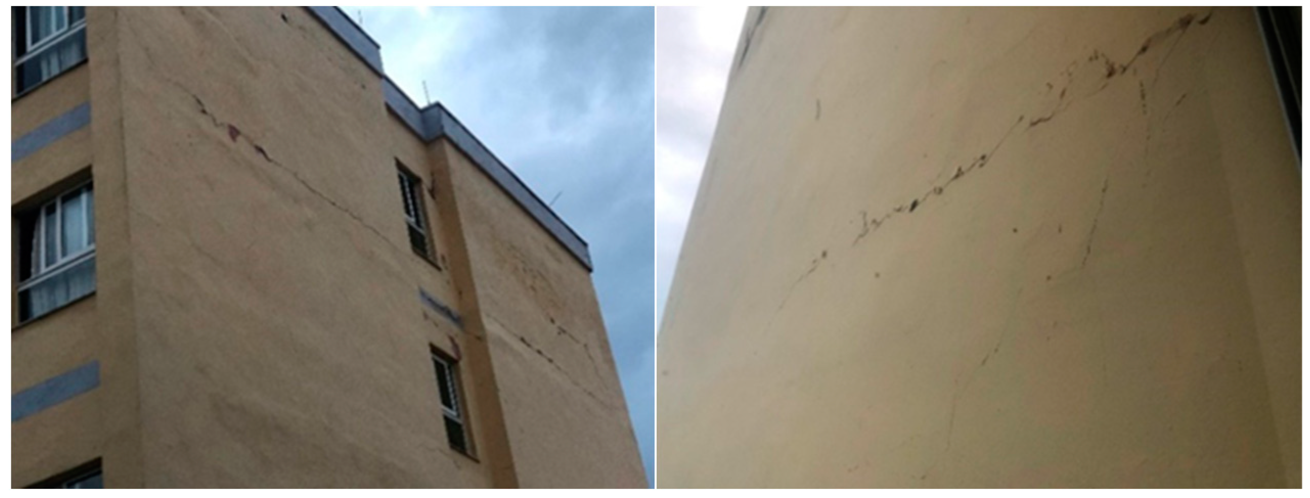
Figure 2 shows a case of a building on an additional floor of a building in Albania and what happened during an earthquake in 2019. How to appropriately design and execute joints (nodes) between the existing structure and new columns is another part of this study. The connection between the elements of the floor or additional floors and the base building cannot be achieved completely by using monolithic, i.e., rigid elements. These connections depend on many factors, such as the difference in material between the old building and the new additional part of the construction.
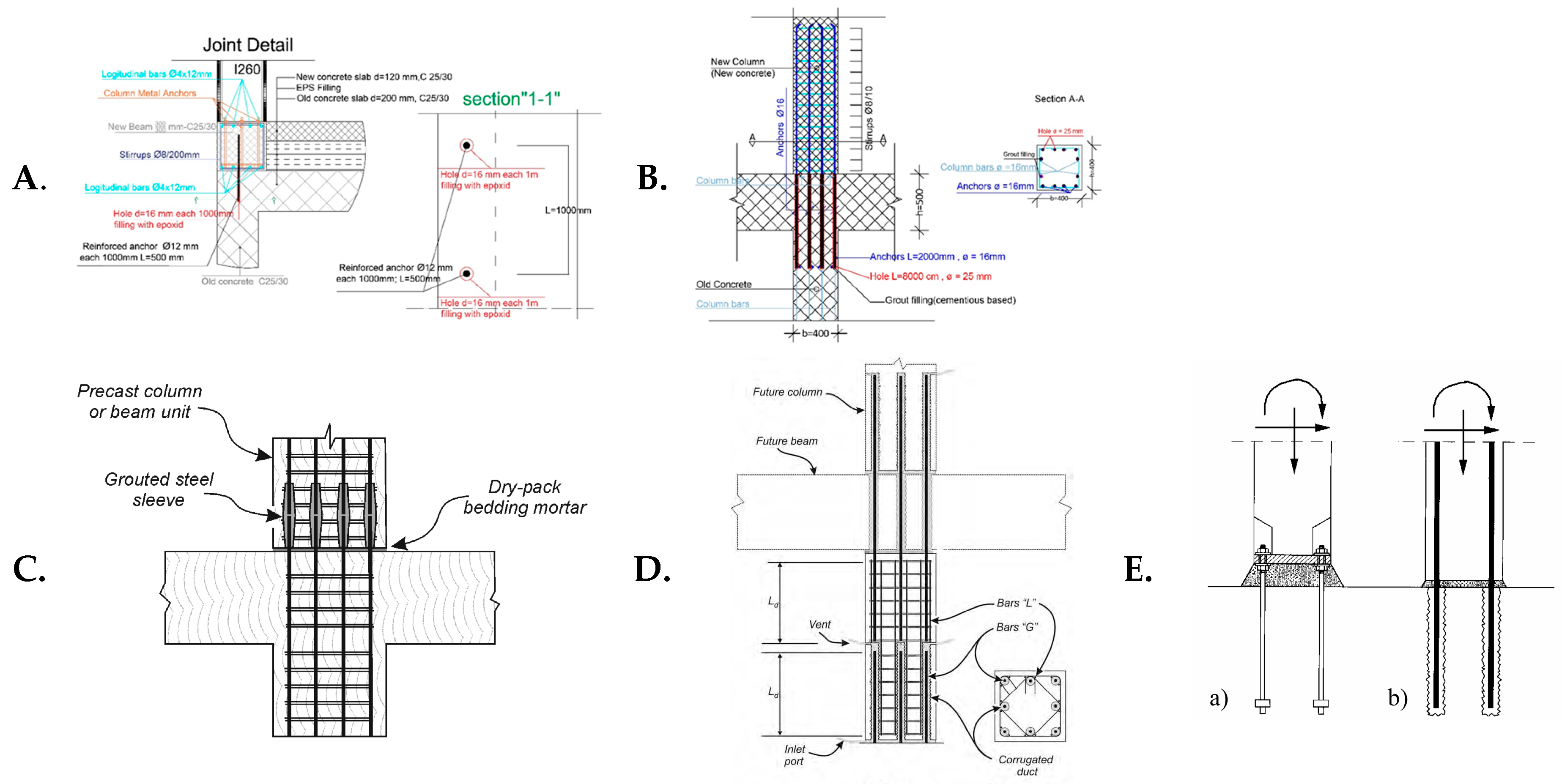
There might also be other issues that negatively impact the connection between the old building and the added floors, such as the impact of dirt accumulated throughout the years or the inadequate opening of the newly made holes that cannot be cleaned effectively and where the cleaning of the hole cannot be monitored. All of these elements lead to a connection with defects, and it cannot be treated as a full monolithic or rigid connection. Similar connection details may be found in prefabricated structures, but the connections made there are safer because the anchorage location is detailed at an appropriate time, and the holes are opened while the structural element is being cast.
Figure 3 illustrates some details that have been used in vertical extensions and prefabricated construction.
The connection of the new and old columns or the column–beam node will also present a problem in terms of the changes in its state. These changes occur when changing from knee nodes to external nodes. If the connection is not rigid and does not interact equally with the other part, the first plastic hinge is located in the connection between the new column and the old one. Also, the action of the outer forces on the nodes change based on the level of its stiffness or rigidity.
Figure 4 shows how the joint and acting forces change.
It is known that within the architectural frame, specifically at the terminal node of the structure, the reinforcement bars end at the ultimate knee node. The addition of a new floor is a problem that requires defining the level of stiffness to be used in the design of these new additions, especially in seismic locations.
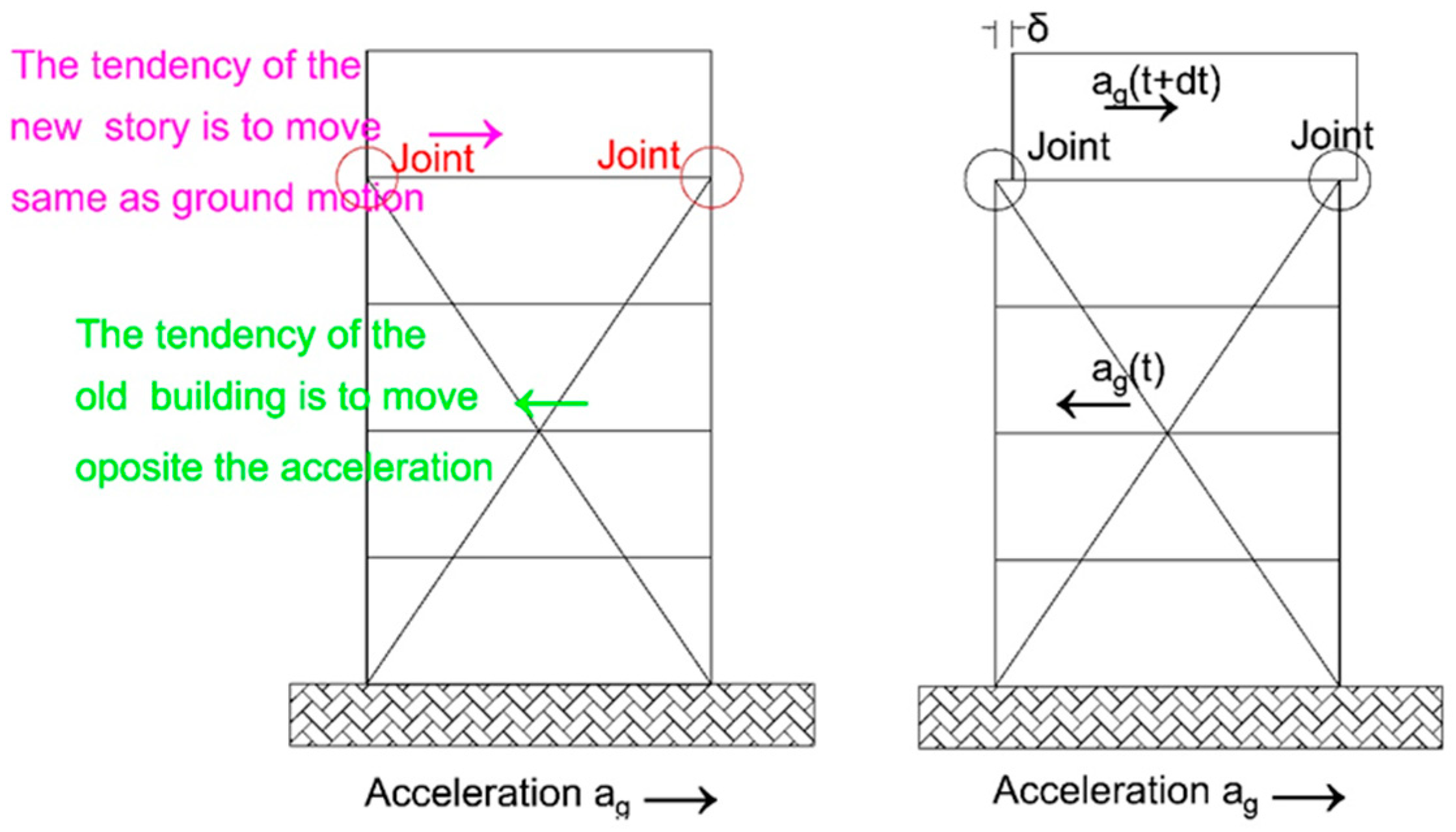
The added construction does not react in the same way as the old (base) building under the action of a dynamic impact. The tendency of the building’s movement under the action of an earthquake is always to act in the opposite direction to the seismic wave. Therefore, if the additional floors are not connected to the existing building by rigid or stiff joints, they will have a tendency to act in the opposite direction from the base building and in the direction of the seismic wave. This is illustrated in
Figure 5.
The case of the slipping of the additional floor is also seen in
Figure 2. In the studied building, there was a tendency for the additional floor to move in the opposite direction to the movement of the base of the building in the earthquake in Albania in 2019.
When this is known at the design stage, the design must be based on the principle of strong columns–weak beams. This principle means that in the case of a collapse, only the beam, floor, or story will collapse, and not the column, which presents a loss in the stability of the building. Therefore, in the case of adding a new floor, this phenomenon will show whether or not the column is rigid enough. There are two plastic hinges in the connecting joint: one in the tied new column and the other in the old beam. This phenomenon is illustrated in
Figure 6.
There are also differences in the vibration modes of the building, depending on whether the added floor is joined by a hinged or stiff connection. The largest changes are observed in the second and third vibrations (
Figure 7 and
Figure 8) and higher.
The issues described are generally not included in codes. To date, a consensus has not been reached on a single-joint modeling technique, either in the scientific literature or in the codes, in spite of the fact that many research groups worldwide, during the last three decades, have performed a wide range of experimental and theoretical studies on this topic to evaluate the cyclic behavior of beam–column joints [
11]. The analogy can also be used in the case of the additional floor joint. Therefore, there is a need for intervention in old buildings where much of the existing building stock exhibits a number of deficiencies, rendering them susceptible to damage from future earthquakes [
12]. The only viable solution is retrofitting, despite the difficulties that may arise from socioeconomic constraints and the lack of an established code framework [
12]. This motivates researchers to contribute to and develop this area of study further in the future in order to ensure the safety of both old structures and those with vertical extensions.
2. Literature Review
Even though the motivation for this study comes from the cases noted in Kosovo, there are many examples of research related to vertical extensions around the world. The following summary provides the details and conclusions of published studies.
Bahrami et al. [
1] explored sustainable population growth and the need for research on expanding the capacities of old buildings. This growth also determines the changes in future constructions. The authors examined the impact of renovations and the construction of additional floors on people’s lives, both financially and environmentally. The analysis of old buildings was performed using software apps and utilizing finite element methods such as StruSoft FEM-Design. The analyzed building was assessed based on on-site data and using norms and coefficients from Eurocodes. The analysis focused on the changes in the expansion of the building in height, intervening at key points of the old structure. Finally, the authors analyzed the effects and capacity of the building elements under the new conditions after the construction of the new floor, comparing the load-bearing capacity before and after reinforcement.
Kyakula et al. [
4] dealt with how existing buildings, constructed according to outdated codes, can be analyzed and the reserve capacity they possess as old structures. The analysis was based on the ULS design analysis according to Eurocode and British standards for cases involving the construction of additional floors. A comparison was made between the ultimate limit state and the expressions used in the design according to linear analysis, and the percentage of reserve capacity in the elements of the old building was determined. The analysis also included an assessment of additional services in new buildings compared to old ones. Evaluations of the foundations, the stress on old buildings, studies of the soil, and the impact on it due to existing construction were conducted. The loads used in the old building were assessed, and the analysis was performed according to the current codes. The possibilities for modifications in vertical elements such as walls and columns and their impact on the building’s foundations were also examined. In conclusion, before proceeding with the construction of additional floors, an investigation into the structural integrity of the building should be conducted. Its capacity should be assessed, and the reserve capacity of the existing elements should be analyzed, which ranges from 9% to 42% depending on the construction elements and load cases.
The focus of the study by Johansson et al. [
7] was the demand for additional floors in existing buildings. This study explored the methods of constructing additional floors in several public buildings and hotels in Sweden. The authors addressed the increasing demand for open spaces and the associated costs, financial impact, and societal implications. The authors also discussed the environmental impacts and examined the methods used in strengthening buildings after the addition of new floors. The load-bearing capacities of elements, the bonding and materials used, and the models to ensure stability were analyzed. Fire safety was also addressed. The advantages and disadvantages of constructing additional floors, considering previous experiences, were taken into account. The study also featured the conditions for constructing additional floors, following technical and urban requirements. A guide was also provided for use in cases of adding extra floors. Static calculations and an inspection of the elements that had been stressed and were subject to additional loads from the added floors were conducted accordingly. The building was not subjected to seismic influences. The authors concluded that different results are obtained depending on the project and approach. Finally, recommendations were imparted.
In
Structural Connections for Precast Concrete Buildings—Guide to Good Practice, prepared by Task Group 6.2 [
10], the group of authors of this guide examined the connecting joints of prefabricated elements. They assessed various connections, such as the column–column, beam–column, and foundation-to-vertical element connections. The research also examined the other connections used with prefabricated elements. Anchorages were discussed, as well as the influence of tangential forces on the anchorage and the connections between elements. The seismic aspect of the connection of prefabricated elements was also addressed in this study. The structural integrity of the building, as a whole and with its connections, was also considered, as well as the behavior of the construction and its connections under horizontal forces and their effects on the structure.
Zhulidova M. [
13] dealt with the behavior of an old building and its load-bearing capacity, as well as the materials used. They took into account the geometric aspect of the elements and the foundation conditions for the possibility of constructing an additional floor. Examples of constructing additional floors using steel structures and their connection to the existing structure were examined. Various cases of adding extra floors in Europe and Russia were considered, and several cases analyzed the advantages and disadvantages of adding floors to these buildings. It assayed the case of adding a metal-structured story utilizing the perimeter of the existing building. The columns were founded on the ground and anchored to the external perimeter walls. This type of addition was implemented to avoid placing any additional load on the old building. The intermediate construction was made of steel without any reliance on the old building. Lightweight materials, such as steel, wood, and lightweight concrete reinforced with composite structures, were used in the walls and floors. Lastly, as a conclusion, the author claimed to have found the best vertical construction method, followed by an analysis of the client’s requirements and financial costs. It was identified that there is a lack of experience in such constructions. However, even in this study case, there was no approach to address the impact on joints from horizontal and seismic loads, only from vertical gravity loads.
The study of Soikkeli A. [
14] focused on a global issue. With the increasing population in urban areas and the need for new construction, there is a risk of diminishing green spaces and agricultural lands. Hence, there arises a need to address the addition of new floors to existing buildings. The author analyzed the use of lightweight materials in constructing these additional floors, as well as the issue of the appearance and impact of old buildings and extra floors on neighboring structures, as well as the social, economic, and esthetic aspects of buildings. The work was fully based on the building regulations in Finland, as revised in April 2011 (Chapter E1). The author also discussed fire protection and other installation systems and the possibility of using prefabricated elements or even containers. However, in this work, there was no treatment of the behavior of buildings regarding seismic influences.
The focus of Sundling R. [
15] was a study review aiming to obtain a better understanding of the reasons and the needs for constructing additional floors. The analysis covered financial and social aspects, environmental impacts, barriers and legislative changes, and the legal permitting process for adding floors to buildings. The methodology of various studies and comparisons between different cases were also discussed, along with analogies and the differences between them. The time of construction, the age of the buildings, and the codes under which they were built, as well as their compliance with current codes, were analyzed. Four cases were examined, and their findings were discussed. Lessons were drawn on how to approach planning and permit acquisition and the assessment of existing structures, reinforcement, and intervention with additional floors. The treatment of connections between the old building and the new floor was also discussed. The materials used in the construction of old buildings were discussed, along with the possibilities of implementation and a strategy consisting of seven phases or stages. The conclusion of this study was to encourage investors and property owners to add floors to their buildings. The knowledge gained from these four case studies should be disseminated, and lessons should be drawn on how to vertically expand buildings by adding new floors to existing ones.
In the study of Shihoara H. [
16], the joint connecting the beam and column was analyzed. It was found that the joint is the key element in the survival of the building and its response to seismic influences. It was observed that the joint could collapse due to seismic actions from shear force, highlighting the importance of proper design. The analysis focused on the equilibrium of external and internal forces and avoiding exceeding the permissible strains in joints. Diagonal cracks in the joint indicate the direction of internal forces. Shihoara analyzed the joint using two methods, known as joint mode equilibrium and beam mode equilibrium. The study concluded that in the cases of external, internal, and corner joints (knee joints), the distribution of strain follows only one rational path. The ratio of joint reinforcement to tangential forces plays a significant role in external joints, whereas it does not have the same impact on internal joints. The capacity of the joint is increased by the adhesion between the reinforcement and concrete, which is a key factor in joints.
In
Eurocode 2: Design of Concrete Structures—Part 1-1: General Rules and Rules for Buildings [
17], the European design standard Eurocode 2 has addressed reinforced concrete structures as well as the connections between beams and columns. The study of this connection was carried out for monolithic cases and corner (knee) joints with open and closed moments. Section 6.5.4 of the code covers the general conditions and equilibrium conditions of the joint (node), outlining the types of joints and their treatment. Section 10 provides a superficial treatment of prefabricated elements, and Section 10.9.4 addresses the connections and supports of prefabricated elements. Section 10 talks about the rules, conditions, and forms of connections. The design, execution, and maintenance conditions of the joints are also discussed, along with the materials used and the possibilities of anchoring. Half-joint connections, the treatment of transverse forces, and when to consider them as a basis or not are also covered. Annex J2 provides the methods for treating corner (knee) joints with open and closed moments and the reinforcement patterns for absorbing moments and shear forces in joints. There are several cases of corner joints, such as joints with columns and beams with equal geometric characteristics. In joints with strong columns and weak beams, the dimensions of the columns dominate compared to the beams, and in joints with weak columns and strong beams, the dimensions of the beams dominate compared to the columns. This code does not address the connection between column and column or column and beam for superstructures or additional stories.
In
Eurocode 8: Design of Structures for Earthquake Resistance—Part 1: General Rules, Seismic Actions and Rules for Buildings [
18], the beam–column joint is addressed under Section 5.4.3.3, which outlines the minimum conditions for the connection of the column on a beam and the amount of reinforcement required. Section 5.11 of the code covers prefabricated elements and their connections. Specifically, the connection between the column and beam is addressed under Section 5.11.2, which provides the conditions for the connection. The distance of the connection from the critical parts of the joint, the design forms, and the dissipation of accumulated energy are discussed. It is mentioned that the joint should have at least 50% of the moment capacity for it to be treated rigidly. Section 5.11.2.2 presents an evaluation of joint resistance, but if any of the methods in EC2 and EC8 do not cover a particular case, experimental studies relating to that problem should be applied. This opens up the path for us to treat our specific case, which is the connection and behavior of additional floor columns in existing buildings. The behavior of additional stories in a typical frame has not been addressed in any case.
The American code for the design of joint connectors for prefabricated elements [
19] describes three types of connections: strong, ductile, and deformable connections. It addresses the conditions and behavior of connections based on the building soil sites and seismic zone conditions. It also covers the use of materials and the anchoring of vertical and horizontal elements. It addresses the minimum concrete class and anchoring lengths. Vertical connections in cases of adding floors to a building or existing frame are not specifically addressed. However, the connection can be used as an analogy, utilizing the requirements that need to be fulfilled. Every connection used in the structural elements must meet the criteria of transferring vertical and horizontal loads, including those from wind and seismic forces, down to the foundation.
In
ACI 318-11: Building Code Requirements for Structural Concrete and Commentary [
20], the method of connection and the role of the connection beam–column, and vice versa, is addressed. In this code, connections are addressed in Section 7, particularly under Section 7.9. The commentary on the connection emphasizes that it should function to continuously ensure a future without damage or failure. Section 11 addresses transversal forces and reinforcement methods for the joints used in monolithic concrete and minimum reinforcement. Section 11.11.7 elaborates on the moment of transfer from the slab to the column and the method of reinforcement. It covers the moment transfer caused by all types of forces. Section 12 addresses the different types of anchorage and anchorage lengths in columns from the slab or beam, as well as the effect of shear forces in the critical zone. Section 16, starting from page 275, treats prefabricated elements, whereas Section R16.2.2 clarifies that the behavior of prefabricated elements is different from monolithic structures, and the connections of elements need to be treated specifically, particularly by considering the seismic loads. The transfer of forces in beam elements is also addressed, taking into account the shrinkage, temperature, and laboratory results of the joints. Connections of elements should also address proper stability and adequate ductility. This has to be applied when the designers use different materials for the connections of elements. Section 21 addresses the aspect of joint behavior in a monolithic concrete frame. This chapter deals with the seismic aspect of the frame and joint and the technical conditions of element embedment, such as columns, beams, and reinforcement bars, to withstand external forces such as bending moment, shear force, or axial force.
In
ACI 550.1R-01: Emulating Cast-in-Place Detailing in Precast Concrete Structures [
21], this code addresses all possible joints and connections between the beam and the column, and the column and other elements. It also covers the determination of plastic hinge behavior. The joints are cast-in-place, specifically on-site. This code also covers the aspect of seismic impacts by enhancing the stability of the structure and the connection itself. It discusses the optimal points for implementing the connection, preferably at locations with the lowest external force effects. Various methods of connection are addressed, such as strong connections, ductile connections, and deformable connections. This is all carried out considering the stability and functionality of the joints in high seismicity zones.
Lazarević et al. [
22] presented the method of adding floors to an existing building. The authors evaluated an old building and analyzed its dynamic and static behavior. The obtained results led the authors to decide to reinforce and renovate the existing building and add five new floors. The additional floors were constructed using a steel structure and external supporting columns. The columns were connected to the building, and the construction of the new floors was also supported by an elevator shaft. The joints and strains at critical points, both in the old and renovated parts of the building, were analyzed thoroughly. The authors analyzed the dynamic behavior according to the conditions of Eurocode 8 and the seismic conditions of Croatia. The construction methods were presented, and the completion of the building was achieved. However, no section provides an analysis of the joints or their behavior in seismic conditions in relation to the old building.
Champirs. DC [
23] explores the retrofits of multi-story buildings by introducing seismic isolation at different levels, emphasizing that the structural response depends on factors such as isolator locations, properties, seismic gap sizes, and earthquake actions. Optimized solutions generally outperform base isolation, especially in scenarios with narrow seismic gaps that may restrict base isolation or lead to high floor accelerations with stiff base isolators. The paper suggests that isolating buildings at various elevations offers advantages over base-only isolation and recommends further exploration and experimental verification of non-conventional isolation concepts. The study proposes potential benefits in the context of a global intervention approach for assessing alternative retrofit schemes. This study addresses cost optimization using isolators for retrofitting existing buildings, examining the seismic behavior changes in six-story structures. The analysis is based on placing isolators in three different scenarios: at the foundation, under floor slabs, and at various locations along the building. The primary objective is to reduce seismic demand by minimizing non-elastic displacements. The employed software sizes and treats the isolators to align with the budget and optimizes them for the specific building. The analysis utilizes seven accelerograms from the most hazardous earthquakes worldwide. In this study, the authors do not consider the case of an existing building where new floors are added and where the connection between new and old concrete is treated. The analysis is confined to enhancing the seismic performance of an existing building using isolators without examining the structural changes to the building.
In the study by Forcellini D. [
24], Forcellini D. based his analysis on high-rise buildings, specifically those with 20 floors, and examined cases of isolator placement at three different heights within the structure. Throughout the paper, the author observes that additional-floor buildings can be treated as cases of using retrofitting methods. The analysis of buildings with additional floors has been conducted analytically by some authors by incorporating isolator placement and the potential loss of stability at various heights of the structure. This study analyzes the placement and configuration of isolators at different heights of buildings, using a structure without isolators as a model for the results comparison. The analysis and calculation of isolators were carried out by Eurocode 8, Section 10, which covers the sphere of isolators. The objective was to reduce the seismic response spectrum of lateral forces by increasing the fundamental period of the building. Isolators were placed at all connection points of the base and on rigid floors at various heights of the buildings. This confirmed that the use of isolators is effective for small- to medium-sized buildings, which also have good feasibility. In this work, the author does not address the connection between additional floors as a specific, separate connection. Instead, all the obtained results are focused on the response of the analyzed cases. In the future, it is suggested that other cases be analyzed by making different configurations and placing isolators in different locations.
4. Discussion of the Results
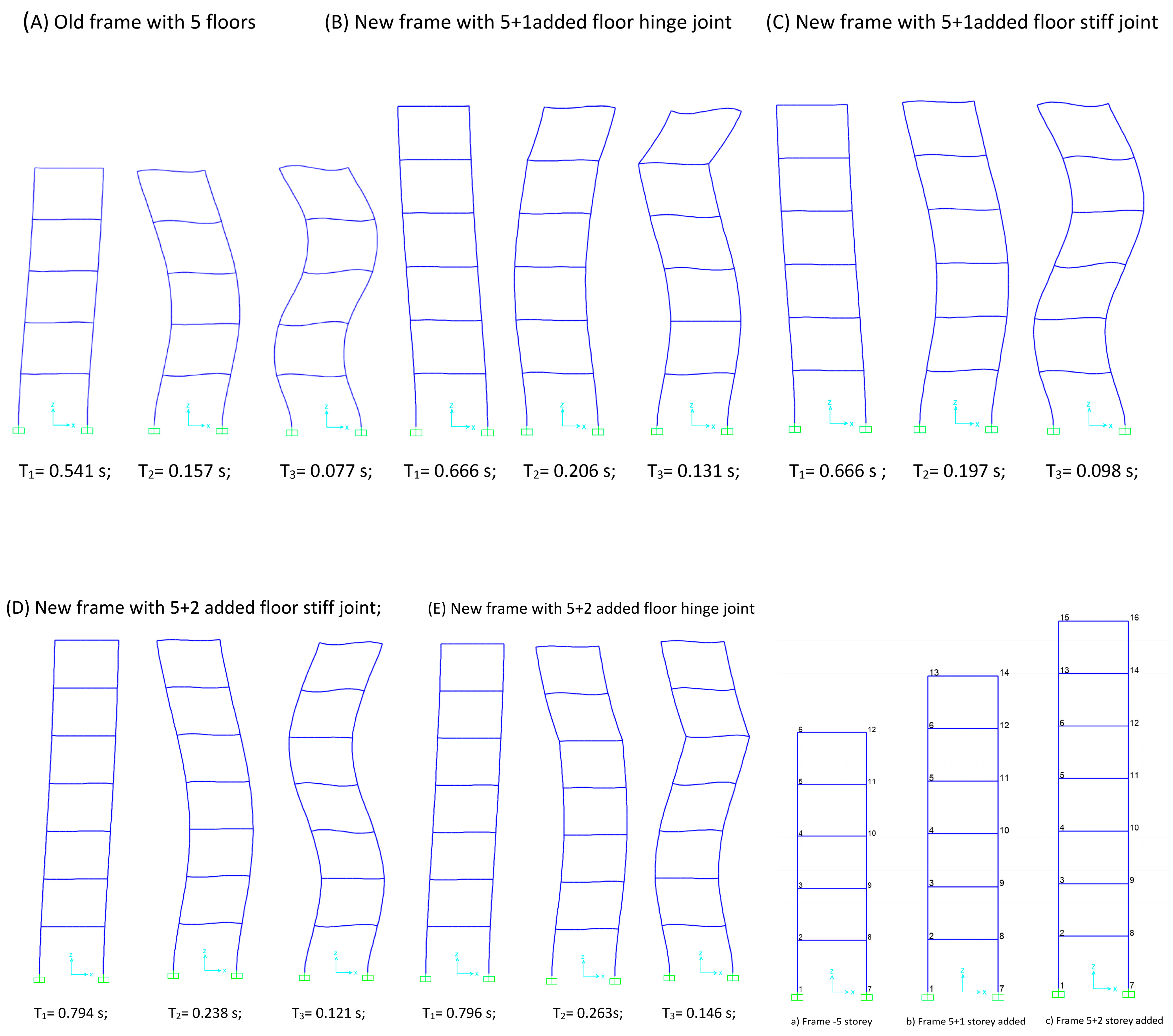
The dynamic characteristics of structures are of particular importance, especially in seismic zones.
Figure 10 presents the vibration modes of three different height frames and the undeformed models of the reinforced concrete frame. The footings are considered fully restrained joints, not taking into account the structure–foundation interactions [
35]. The first three vibration modes tell us that as the height increases, the first period of the frame or structure also increases. The base frame is represented in
Figure 10A and has a regular form of periods.
Figure 10B,C present the frame with an additional floor. The characteristic of this frame is the connection with the existing ones, executed in two ways: rigid or hinged. The periods differ in shape and behavior compared to the periods of the base frame. Not only between the additional floor frames but also within the frames, as shown in
Figure 10B,C, there is a difference in behavior depending on the implemented connection. The stiffness is different, which affects the quality of the additional frame connection.
Figure 10D,E also depict that there is a loss in stiffness in areas where we have a higher value of periods, depending on the connection. With the increase in the number of floors, the possibility of dynamic value changes in the structure also increases. In this case, there is also a change in the direction of the base periods. This implies that the behavior of an exterior beam–column connection is very complex since the failure modes of the RC joint are not only dependent on the joint but also depend on the connecting elements [
36]. Here, we observe the tendency of the detachment of the additional frame at the connection, trying to move in the opposite direction to the inertia of the frame, which occurs in the case of ground motion. In other words, the additional frames tend to move in the same direction as the ground motion. The generally used design of the connection does not behave as an integral part of the old structure, as evidenced by the periods presented in
Figure 10.
Table 1 presents the numerical values of the periods and frequencies for the cases shown in
Figure 10. It is clear that the difference in periods between the same model varies depending on the type of connection adopted. The participation of mass in the modal analysis is satisfactory in terms of the EC8 criteria (90% of the mass activated in the first three modes) and is shown in
Table 1 for the first three periods.
Table 1 also presents the maximum displacement of the models according to the first three periods under the seismic action, a
g = 0.25 g. It is clearly observed that the addition of floors not only changes the behavior and direction of the vibration, as seen in the mode shapes, but it also affects the displacement due to seismic action, depending on the connection between the additional floor and the existing frame. This difference is more pronounced in the second and third periods, indicating the phenomenon of the counter-directional action of the additional floors compared to the existing structure. Therefore, we posit that beam–column joints have a significant role in shaping the RC frame-building resistance to different loading conditions [
37]. The proper treatment of the connection between the new structure and the existing one and its adequate solution is crucial. This is especially important for buildings with great cultural and historical value and for buildings [
38] intended to have extra floors.
Table 2 shows the displacements of joints 6, 13, and 15. These joints were selected based on the fact that joint 6 is being connected to the new frame, while joints 13 and 15 are the joints of the new frames. The obtained results are derived from the displacement in the
x- and
z-axes and are expressed in meters. These results also demonstrate that the more floors that are added, the more diverse the behavior of the floor towards a structure without additions or constructed with rigid, semi-rigid, or hinged connections. The comparison of displacements is always carried out between the old frames and new frames with an additional connection on the old structure at the same points.
Table 3 presents the acceleration results at the respective joints, which are the focus of the analysis. The acceleration in the vertical direction of the building changes relative to the base acceleration presented. The seismic acceleration a
g = 0.25 g was considered, while at the joints, it was increased depending on the height and stiffness of the joint, considering the connection between the existing frame and the new one. Herein, from these results, it can be seen that the acceleration in the frame is higher in cases where there are no rigid connections between the new and old frames. Therefore, it is crucial to determine the correct stiffness of the joint in cases such as additional construction or additional floors in seismic zones. For non-seismically designed (NSD) structures, it is very important to model the nonlinearities in the beam–column joints in order to capture realistic seismic behavior [
39].
Table 4 presents the effects on joints 6, 13, and 15 from the external forces. This table shows the changes regarding joint 6 in cases where there is no addition and in cases where the additional floors are part of the existing frame.
Figure 12 schematically shows the connection that is commonly realized and the deformation of joint 6 depending on the stiffness of the connection between the old and new frames.
In cases of stiff connection, the deformation will be similar to the one shown in
Figure 12b. If there is a pinned connection, then the deformation will be as shown in
Figure 12c. Implementing the connection, as shown in
Figure 12a, does not guarantee that the connection is rigid, or at least, it indicates a sufficient level of stiffness that would classify its behavior as rigid. Therefore, additional research is needed to understand how this joint behaves. Depending on the impacts on the joints presented in
Table 4, the joint will change behavior, as shown in
Figure 4. The change will not only be evident in the external form but also in the internal forces, which will undergo a behavior change. This change occurs because the shape of the joint changes from a joint with two elements to a joint with three elements and for different connections.
The outcome results in
Table 4 indicate that the case shown in
Figure 13c needs to be addressed in order to determine the distribution of internal forces within the joint. Consequently, tests should be conducted to verify the value of stiffness in the connection between the new and existing elements. Repaired structures, structural members, and connections must be designed to have design strengths at all sections that are at least equal to the required strengths calculated for factored loads and forces in the combinations specified in ACI 562M-13 [
40]. The examination of this joint will be decisive for the future reconstruction and repair of old buildings for safer utilization.
5. Conclusions
The performance and behavior of the frame in five different scenarios using connections with varying stiffness and different additional floors have been assessed through modal analysis. Various comparisons have been conducted by using dynamic characteristics such as periods, frequencies, mass participation, displacements, accelerations, etc., to conclude that the behavior changes in relation to the increase in the number of floors and the manner of stiffness in the connection.
A frame with added floors behaves differently compared to one without extra floors, even when rigid connections are used. In the case of frames with added floors, there is a tendency for the floor to shift in the opposite direction to the base structure under seismic action. This proclivity induces a displacement or a partial detachment of the flooring from the existing old structure, attributable to the seismic vibrations generated by earthquake waves. In light of this, we concluded that designs that consider the joint to be rigid are inadequate because the structure does not behave in such a way. The node, which was initially central up to the addition of the new floors, now changes the behavior of the internal forces depending on the achieved stiffness of the node explored in additional research. For the structural behavior, both individually and with the additional floors, a new form of the node’s connection must be selected. The results are confined to the specific cases considered in this study.
From the analysis, this connection can be used in cases where the building meets the technical and seismic requirements for accommodating additional loads.
If the building does not meet the seismic conditions according to standards such as Eurocode 8, then retrofitting of the structure is necessary to fulfill the requirements for additional floors and the use of this connection.
The addition of extra floors and the use of this connection should never be considered without a comprehensive static and seismic analysis of the building conditions that are based on the characteristics of the existing materials. Accordingly, further studies will be conducted focusing on the following cases:
Conducting experimental studies to determine the stiffness coefficient of the connecting joint.
Conducting studies to determine the behavior of the structure as a whole under seismic loads.
Conducting surveys on the behavior of internal forces in joints when the function changes from a cornered or knee joint to an exterior joint.
Future research should further focus on other scenarios, such as three-dimensional analysis, the addition of frame bays, etc.


