Article

A Novel Model for Calculating Human-Body Angle Factor in Radiant Heat Transfer: Balancing Computation Accuracy and Speed

College of Civil Engineering, Hunan University, Changsha 410081, China
*
Author to whom correspondence should be addressed.
Buildings 2024, 14(2), 366; https://doi.org/10.3390/buildings14020366
Submission received: 20 December 2023 / Revised: 25 January 2024 / Accepted: 26 January 2024 / Published: 29 January 2024
(This article belongs to the Section Building Energy, Physics, Environment, and Systems)

Abstract

:
With the growing interest in radiant heating and cooling systems, driven by their improved efficiency and enhanced thermal comfort compared to air systems, there is an increasing need to develop a more accessible method for designers to understand the implications of radiation heat exchange between the human body and radiant panels. To address this, a novel angle factor calculation model, named the HNU Angle Factor Model, was developed, taking into account the spatial arrangement and geometric relationship between the human body and radiant panels. The angle factors obtained using the HNU Angle Factor Model exhibited good agreement with the results obtained with Fanger diagrams and the contour integral method, with average relative differences of 8.1% and 10.0% for 140 cases, respectively. Furthermore, placing a radiant panel on the floor while maintaining its fixed size can contribute to the creation of an even and efficient thermal environment for individuals in both seated and standing positions. By implementing the HNU Angle Factor Model in practical engineering applications, more effective utilization of radiant systems can be achieved, as it provides an evaluation of the heat transfer between the human body and radiant panels.

1. Introduction

With the growing interest in radiant heating and cooling systems due to their improved efficiency and thermal comfort compared to air systems [1,2,3,4,5,6,7,8,9], there is a pressing need to develop a more user-friendly method that enables designers to comprehend the implications of radiation heat exchange between the human body and radiant panels [10]. One of the key parameters that signifies the radiant heat exchange between a human body and its surroundings is the Mean Radiant Temperature (MRT) [11].
The Mean Radiant Temperature (MRT) is a crucial parameter for evaluating the impact of radiant surfaces on a human body, allowing HVAC engineers to design effective and energy-efficient radiant heating and cooling systems. However, obtaining accurate MRT results requires a reliable and efficient method. Some researchers have suggested that the MRT can be measured using instruments [12] like a globe thermometer, two-sphere radiometer [13], or constant air temperature sensor. Certainly, the use of MRT measuring instruments can obtain the MRT of one location quickly and accurately, but the measured results cannot reflect the MRT between a radiant panel and the whole human body, as the height and surface area of a human body matter in the MRT. Therefore, the innovation of calculation methods for the MRT based on the heat transfer between a human body and radiant panels is necessary.
The MRT can be calculated using various factors, including the plane radiant temperature [12], angle factor [14], and other relevant parameters [15]. For methods that employ the panel radiant temperature, the mean radiant temperature can be calculated by multiplying the six measured values by the relevant projection factors provided in ISO 7726, adding the resultant data, and dividing the result by the sum of the projected area factors [12]. In comparison to methods that rely solely on the panel radiant temperature, which provide a quick but potentially less accurate estimation of the MRT, the angle factor offers greater flexibility and universality for assessing the radiant heat exchange. The MRT is calculated as the mean value of the surrounding temperatures weighted according to the magnitude of the respective angle factors. The angle factor represents the fraction of the energy leaving one surface that is incident upon another surface [14]. Obtaining angle factors between a human body and radiant panels quickly, conveniently, and reliably is crucial for the design and operation of radiant systems.
Generally, the angle factor can be obtained in the following three ways: (1) modeling the target area and using professional software like ANASYS 2020 to calculate the angle factor; (2) employing mathematical methods like integral methods for angle factor calculations; and (3) utilizing radiation data collected from experiments. Each of these methods has its own advantages and is applicable in specific situations.
Mathematical methods offer reliable results in the calculation of angle factors but require proficiency in mathematical skills to avoid potential miscalculations. Many researchers have investigated the processes of mathematical methods. Sparrow developed a new and simpler formulation for radiative angle factors. With the help of the Stokes’ theorem, the usual area integrals can be replaced by more tractable contour (i.e., line) integrals, and the order of the integrals (i.e., double reduced to a single and quadruple reduced to a double), which must be evaluated to calculate the angle factor, can be reduced [14]. In the following research, contour integrals were used to calculate the angle factors between the human body and radiant panels. Zheng et al. [16] established basic mathematical expressions of radiation angle factors between the human body and radiation panels using the contour integration method and the algebraic method. They also proved the rationality of contour integral methods, which provides new inspiration for the calculation of the angle factor. In addition, La Gennusa et al. [17] provided a generalized analytical relation based on integral methods. This finding is useful for the computation of angle factors and also for presenting angles in cases in which rectangular surfaces show tilting and rotation. Wang et al. [18] proposed a simplified expression of the angle factor between the human body and the surrounding area. On this basis, the authors formed the construct sample and fitting formulas, which can be applied in the computation of angle factors for an area with the conditions of length (3–10 m), width (3–10 m), and height (2.5–10 m) using linear algebraic equations.
On the basis of the mathematical model, professional simulation software is capable of providing accurate results for the human body at any location within the calculated area, which requires a geometry model of the computing targets and a large amount of computing resources. Thus, many researchers have made efforts to optimize the calculation process of computer software. Zmeureanu et al. [19] developed a computer model, called the WIN-THER model, for the evaluation of the impact of radiation from windows on people’s thermal sensations. The speed of calculating the MRT obtained by the WIN-THER improved, and the results indicated good agreement compared with the other three methods. Catalina et al. [20] conducted the radiosity method to calculate the MRT. They reported that commercial CFD software can be a tool to evaluate the thermal comfort level of radiant cooling indoor environments with the application of the MRT. Wang et al. [21] built a simplified 3D human body model for a Chinese adult figure. With the help of the ANSYS Fluent software, angle factors between the human body and the radiant panel were obtained based on the surface-to-surface model (S2S). Li et al. applied TAITherm software (ThermoAnalytics) to obtain the angle factors for human bodies that have heights in the range of 70–230 cm [22].
However, despite the two methods explained above, angle factors can be obtained using radiation data collected from experiments. Fanger et al. carried out an experiment to obtain the angle factors between the human body and a room’s surface. Later, Fanger [23] integrated the acquired data and transformed the data into diagrams. These diagrams are convenient for looking up an angle factor according to the length, width, and height of a computing area. Fanger’s research is considered a great contribution to the study of radiant transfer between the human body and indoor environments, and it is included in ISO 7726 [12] for the calculation of angle factors between the human body and thermal environments. On this basis, Horikoshi et al. [24] measured angle factors between standing or sedentary postures and rectangular planes. They also calculated the effective radiation area with a photographic method, using an orthographic lens for the measurements. Kalisperis et al. [25] developed angle factor tables for a variety of inclined surfaces using Fanger’s data.
To sum up, mathematical methods offer reliable results for calculating angle factors but require proficiency in mathematical skills to avoid potential miscalculations. For detailed numerical analyses, professional simulation software is capable of providing accurate results for the human body at any location within the calculated area. However, professional simulation software requires expertise in modeling and numerical simulation, and the computational demands of this method can be significant. In practical applications, designers prefer convenient and quick estimations for a small number of angle factors. The development of Fanger diagrams is recommended by the International Organization for Standardization in ISO 7726 and ASHRAE in the ASHRAE Handbook—Fundamentals, requiring that designers carefully examine the diagrams to obtain precise results. At the same time, the application of Fanger diagrams is limited by the size of the calculated area, and it can be challenging to obtain angle factors between the human body and radiant panels at different locations within an area. In practical engineering applications, it is desirable to have angle factor calculation methods that are user-friendly for nonprofessional numerical simulation operators and offer fast processing speed and reliable accuracy for engineering applications.
Thus, the research gaps in the current calculation of angle factors for practical application can be concluded as follow: (1) The calculation process is tedious and error prone. (2) To obtain the distribution of angle factors or the MRT requires the employment of professional numerical simulation software, which is time-consuming and requires sufficient computing resources. (3) Current methods for the calculation of angle factors are difficult when comparing angle factors of differently designed sizes of radiant panels installed at different locations. (4) The effect of the air temperature and radiant panel temperature on the MRT and operative temperature can only be obtained using professional numerical simulation software or building energy simulation software.
To solve the mentioned gaps, this paper introduces a novel model, the HNU Angle Factor Model, for calculating human-body angle factors in radiant heat transfer. The model is based on the relative spatial position relationship between the human body and radiant panels. The paper provides a detailed description of the HNU Angle Factor Model and compares the results with those using Fanger and the contour integral method developed by Zheng et al [16]. Then, the present study used the HNU Angle Factor Model to compare the angle factor distribution among three different instillation locations (ceiling, floor, and vertical surface) for standing or sedentary postures. More importantly, with the help of the HNU Angle Factor Model, the MRT field of the whole computed area is obtained conveniently. Thus, the present study compares the MRT field and operative temperature field among three different instillation locations for standing or sedentary postures at different air temperatures, which can allow designers to easily evaluate the energy consumption. This paper also showcases the potential applications of the HNU Angle Factor Model and discusses the advantages and characteristics of different angle factor calculation methods.
The HNU Angle Factor Model may provide a more convenient and efficient way to obtain angle factors. This method can also help to compare the effect of radiant systems and thermal comfort on human occupancy among different sizes of radiant panels installed at different locations.

2. Methods

2.1. Existing Methods for Calculating Angle Factor

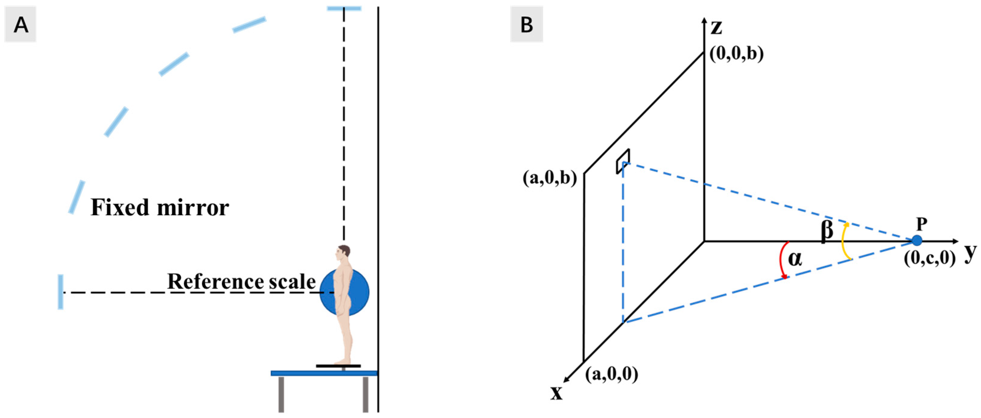
2.1.1. Angle Factor Obtained by Experiments (Fanger’s Method)

In early explorations, angle factors between the human body and its surrounding surfaces were obtained through experiments [23]. To be specific, Fanger set up an optical system that consisted of (1) a small, plane precision mirror that could pivot around a horizontal axis and (2) six large fixed plane mirrors placed in a vertical quarter circle, with the human subject remaining standing or seated on a platform in the center. In addition, a fixed camera was used to photograph the subject from six different angles (altitudes, β) by turning the small mirror, and a total of thirteen horizontal angles (azimuth, α) could be obtained. The platform was turned 15° at a time, and 78 photographs could be obtained within a quarter sphere. A reference scale was placed beside the subject to help with computing the exact angle factor by converting the plane-metered areas to the actual projected areas. A diagram of the system is exhibited in Figure 1A.
When the surrounding faces of a subject are combined and considered as a whole large sphere (A2), Ap is the person’s projected area on a plane perpendicular to the direction of a surface element (dA2) with the angle coordinates (α, β). By taking photographs of the human body at different positions and with the reference scales, the key parameter (Ap) can be calculated. Then, the effective radiation area of the subject (Aeff) can be obtained as follows [23]:
A e f f = 4 π α = 0 α = π β = 0 β = π 2 A p cos β d α d β
Subsequently, the angle factor (FP-A) between the person and the rectangle’s surface is calculated as follows:
F P - A = 1 π x y = 0 x y = a c z y = 0 z y = b c f p [ 1 + x y 2 + z y 2 ] 3 2 d ( x y ) d ( z y )
f p = A p A e f f
where x, y, and z are the coordinate values that define the location of the human body and the diagram of the notation pertinent to the evaluation of the angle factor between a person (as shown in Figure 1B; the body’s center is at point P and facing toward the center of the coordinate system) and a rectangle in the x–z plane.
Eventually, Fanger plotted the results of the experiments and calculations in the form shown in Figure 2, which allows users to obtain angle factor values using the values of a/c and b/c as the inputs.

2.1.2. Angle Factor Obtained Using Contour Integral Method

In later research, to simplify the calculation process, the human body was described as a hexahedral whose surface area was equal to the effective radiation area of the actual human body. A calculation method for the angle factor based on the contour integral method and simplified human body model was developed by Zheng et al. [16]. The size of the simplified human body model is 0.15 m × 0.3 m × 1.55 m (2A × 2B × 2H) for a standing person and 0.28 m × 0.28 m × 1.20 m (2A × 2B × 2H) for a sedentary person. As shown in Figure 3, the calculation of the angle factor between the human body and a horizontal surface is divided into three parts: FP-Az, FP-Ax, and FP-Ay.
For interchange between two finite surfaces, A1 and A2, the angle factor may be derived as follows:
F A 1 - A 2 = 1 A 1 A 1 , A 2 cos β 1 cos β 2 d A 1 d A 2 π r 2
where r represents the distance between locations (x1, y1, z1) and (x2, y2, z2), β 1 represents the angle between normal to dA1 and the connecting line between dA1 and dA2, and β 2 represents the angle between normal to dA2 and the connecting line between dA1 and dA2. The basic mathematical tool that is needed to carry out the analysis is Stokes’ theorem, which transforms an area integrated into a contour (i.e., line) integral. Stokes’ theorem states that given an area A with a boundary curve C, it follows that:
c P d x + Q d y + R d z = A [ l R y Q z + m P z R x + n ( Q x P y ) ] d A
By using Stokes’ theorem, the formulation of the angle factor using the contour integral method can be described as follows:
F A 1 - A 2 = 1 2 π A 1 C 1 C 2 ln r d x 1 d x 2 + ln r d y 1 d y 2 + ln r d z 1 d z 2
The notation pertinent to the evaluation of the angle factor between a human body and a finite surface is illustrated in Figure 3, and the detailed reasoning process of the contour integral method is exhibited in the Supplementary Materials.
Therefore, the angle factors between Ax, Ay, and Az and a finite surface can be obtained by the following:
F A x - P = 1 8 π B H B B d x 0 L ln [ ( y x ) 2 + ( W A ) 2 + d 2 ] [ ( y x ) 2 + ( 2 H + d ) 2 ] ( y x ) 2 + ( W A ) 2 + ( 2 H + d ) 2 [ ( y x ) 2 + d 2 ] d y
F A y - P = 1 8 π A H A A d x 0 W ln [ ( y x ) 2 + ( L B ) 2 + d 2 ] [ ( y x ) 2 + ( 2 H + d ) 2 ] ( y x ) 2 + ( L B ) 2 + ( 2 H + d ) 2 [ ( y x ) 2 + d 2 ] d y
F A z - P = 1 8 π A B A A d x 0 W ln ( y x ) 2 + ( L + B ) 2 + d 2 ( y x ) 2 + ( L B ) 2 + d 2 d y + B B d x 0 L ln ( y x ) 2 + ( W + A ) 2 + d 2 ( y x ) 2 + ( W A ) 2 + d 2 d y

2.2. HNU Angle Factor Model

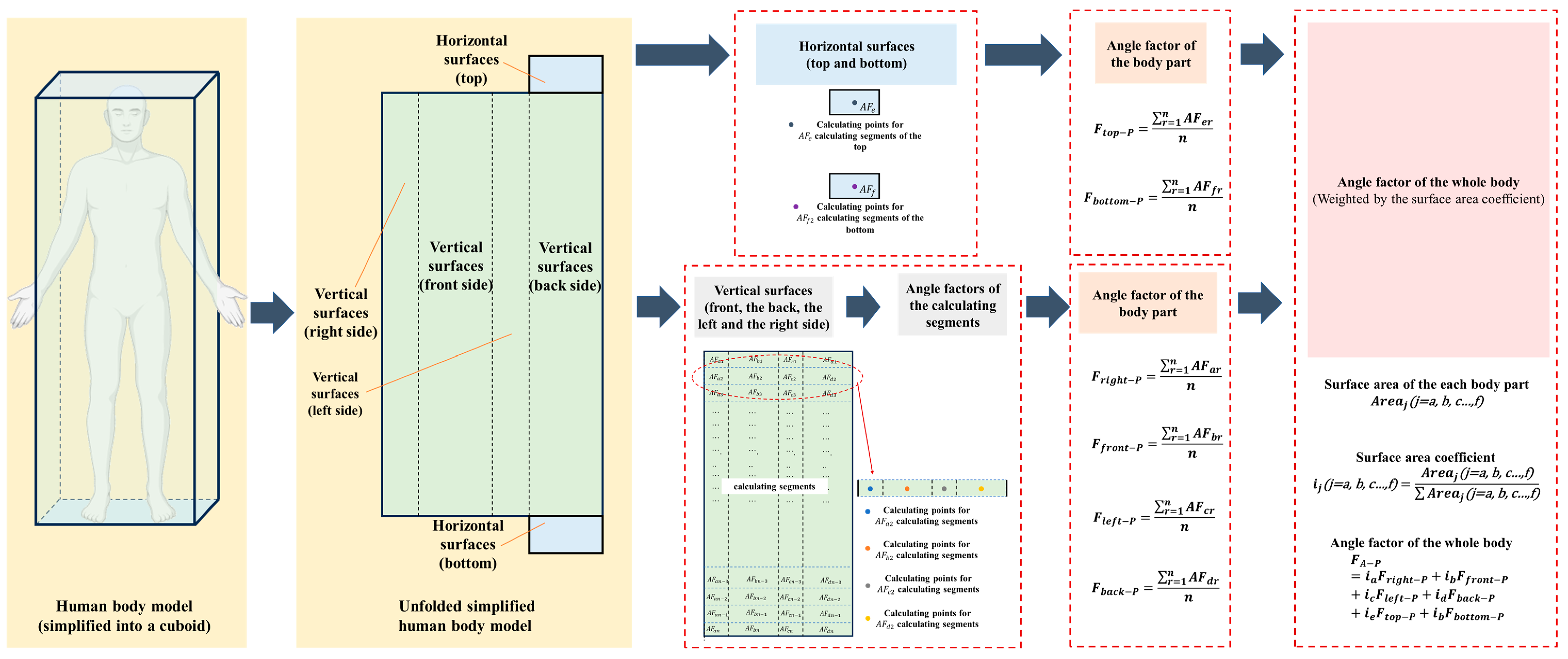
2.2.1. Human Body Model

It is well known that the surface of the actual human body is irregular and uneven. As a pure mathematics model, a human body model that is regular and can describe the actual human body can achieve high accuracy with the HNU Angle Factor Model. Thus, the HNU Angle Factor Model regards the actual human body as a regular hexahedral, and the human body model is flexible for not only standing and sedentary persons but also different races and builds of person. To illustrate the calculation results of the HNU Angle Factor Model, the human body model of the HNU Angle Factor Model is hexahedral with the size of 0.28 m × 0.28 m × 1.20 m for a sedentary person and 0.15 m × 0.3 m × 1.72 m for a standing person, and the surface area was 1.50 m2 and 1.64 m2, respectively. The human body models were chosen for the following two reasons: Firstly, the DuBois surface area is a general body surface area of a nude body; however, in practical situations, the Aeff, effective radiation area of a subject matters for the angle factor and MRT [23]. The Aeff can be determined, as follows [23]:
A e f f = f e f f × f c l × A D u
where f e f f is the coefficient of the effective radiation area, f c l is the clothing area factor, and A D u is the body’s surface area (i.e., DuBois area). A D u can be determined by the height and weight, as follows [26]:
A D u = 0.203 W 0.425 × H 0.725
The average height and weight of Chinese male adults ages 20–59 are 172 cm and 70.4 kg [27]. Thus, A D u = 1.83   m 2 , f e f f = 0.784 , f c l = 1.15 ,   a n d   A e f f = 1.64   m 2 . The surface area of the human body model for the HNU Angle Factor Model is the same as the effective radiation area of a Chinese male adult. This is more suitable for Chinese individuals, whose physiques are not as strong as those of the people in the research of DuBois. Secondly, a simplified human body model can help to improve the calculation speed with a satisfiable accuracy. According to a previous study, the hexahedral model can be optimized for the best fit with Fanger’s data [28], which is widely recognized.
The HNU Angle Factor Model divides the human body model into six parts: top, bottom, front, back, left, and right surfaces. For the vertical surfaces of a human body, like the front, back, left, and right, the angle factor changes with the height of the calculation point. Thus, the vertical surfaces of the human body should not be represented by one point. In the HNU Angle Factor Model, these vertical surfaces of the human body were divided into several segments according to the height of the human body model. Then, the average of these segmental angle factors is regarded as the angle factor of the human body part. For the horizontal surfaces of the human body, like the top and the bottom sides, the segmental angle factor is determined by their central point. Finally, the overall angle factor of the whole human body is determined by the angle factor of each body part weighted by the percentage of the area. The workflow of the calculation process is shown in Figure 4. A detailed calculation process is described in the following subsections.

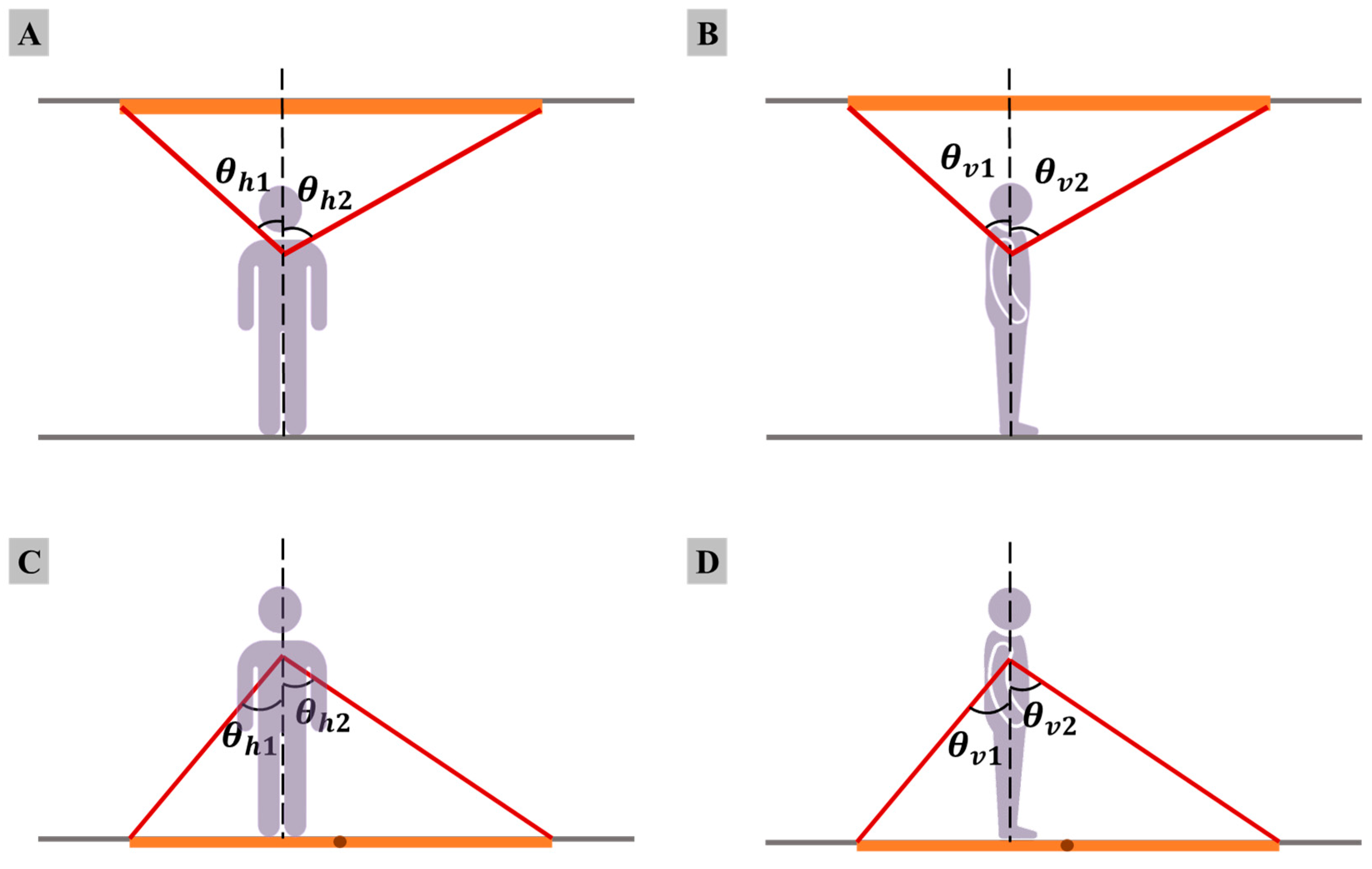
2.2.2. Human Body vs. Horizontal Plane

For horizontal planes, like floors and ceilings, the relative relationship between the human body and a radiant panel is shown in Figure 5. The angle of the side direction of the calculated segment is marked as θ h , and the front direction is marked as θ v . A detailed calculation for every part is described as follows.
The angle factor F A - P is the ratio of the radiant heat transfer area to the whole space around the human body. It is assumed that each vertical surface of the human body part is divided into n segments. As shown in Figure 5, for the front and back sides of the human body, θ h 1 represents the angle between the calculation point of the human body and the left side of the radiant panel divided by the midcourt line of the human body, and θ h 2 represents the angle between the calculation point and the other side of the radiant panel. θ h represents the angle between the calculation point and the radiant panel, which is calculated using θ h 1 and θ h 2 . For the left and right sides of the human body, θ v 1 represents the angle between the calculation point of the human body and the left side of the radiant panel divided by the midcourt line of the human body, and θ v 2 represents the angle between the calculation point and the other side of the radiant panel. θ v represents the angle between the calculation point and the radiant panel, which is calculated using θ v 1 and θ v 2 . The segmental angle factors of each human body part are calculated as follows:
The angle factor for the top of the human body, F A 1 - P , and the area ratio i 1 for a panel installed on the ceiling:
θ h = θ h 1 + θ h 2
F A 1 - P = sin θ v 1 + sin θ v 2 × θ h 360 n
and for a panel installed on the floor:
F A 1 - P = 0
i 1 = t h e   s u r f a c e   a r e a   o f   t h e   t o p t h e   s u r f a c e   a r e a   o f   t h e   w h o l e   h u m a n   b o d y   m o d e l
The angle factor for the bottom of the human body, F A 2 - P , and the area ratio i 2 :
F A 2 - P = 0
i 2 = t h e   s u r f a c e   a r e a   o f   t h e   b o t t o m t h e   s u r f a c e   a r e a   o f   t h e   w h o l e   h u m a n   b o d y   m o d e l
It is assumed that each vertical surface of the human body part is divided into n segments. The angle factor for the front of the human body, F A 3 - P , and the area ratio i 3 :
θ h = θ h 1 + θ h 2
F A 3 - P = sin θ v 2 × θ h 360 n
i 3 = t h e   s u r f a c e   a r e a   o f   t h e   f r o n t t h e   s u r f a c e   a r e a   o f   t h e   w h o l e   h u m a n   b o d y   m o d e l
The angle factor for the back of the human body, F A 4 - P , and the area ratio i 4 :
θ h = θ h 1 + θ h 2
F A 4 - P = sin θ v 1 × θ h 360 n
i 4 = t h e   s u r f a c e   a r e a   o f   t h e   b a c k t h e   s u r f a c e   a r e a   o f   t h e   w h o l e   h u m a n   b o d y   m o d e l
The angle factor for the right side of the human body, F A 5 - P , and the area ratio i 5 :
θ h = θ h 1
F A 5 - P = sin θ v 1 + sin θ v 2 × θ h 360 n
i 5 = t h e   s u r f a c e   a r e a   o f   t h e   r i g h t   s i d e t h e   s u r f a c e   a r e a   o f   t h e   w h o l e   h u m a n   b o d y   m o d e l
The angle factor for the left side of the human body, F A 6 - P , and the area ratio i 6 :
θ h = θ h 2
F A 6 - P = sin θ v 1 + sin θ v 2 × θ h 360 n
i 6 = t h e   s u r f a c e   a r e a   o f   t h e   l e f t   s i d e t h e   s u r f a c e   a r e a   o f   t h e   w h o l e   h u m a n   b o d y   m o d e l
Thus, the overall angle factor, F A - P , between the human body and horizontal planes can be obtained as follows:
F A - P = i 1 F A 1 - P + i 2 F A 2 - P + i 3 F A 3 - P + i 4 F A 4 - P + i 5 F A 5 - P + i 6 F A 6 - P
More calculation methods for the different relative relationships between the human body and the horizontal radiant panel are listed in Supplementary Materials File S1.

2.2.3. Human Body vs. Vertical Plane

As shown in Figure 6, for the front and back sides of the human body, θ h 1 represents the angle between the calculation point of the human body and the left side of the radiant panel and divided by the midcourt line of the human body, and θ h 2 represents the angle between the calculation point and the other side of the radiant panel. θ h represents the angle between the calculation point and the radiant panel, which is calculated using θ h 1 and θ h 2 . For the left and right sides of the human body, θ v 1 represents the angle between the calculation point of the human body and the left side of the radiant panel divided by the midcourt line of the human body, and θ v 2 represents the angle between the calculation point and the other side of the radiant panel. θ v represents the angle between the calculation point and the radiant panel, which is calculated using θ v 1 and θ v 2 .
It is assumed that each human body part is divided into n segments. The angle factors F A i - P is of each human body part and calculated as below:
1
The angle factor for the top of the human body, F A 1 - P , and the area ratio i 1 :
θ h = θ h 1 + θ h 2
F A 1 - P = sin θ v 1 + sin θ v 2 × θ h 360 n
i 1 = t h e   s u r f a c e   a r e a   o f   t h e   t o p t h e   s u r f a c e   a r e a   o f   t h e   w h o l e   h u m a n   b o d y   m o d e l
2
The angle factor for the bottom of the human body, F A 2 - P , and the area ratio i 2 :
F A 2 - P = 0
i 2 = t h e   s u r f a c e   a r e a   o f   t h e   b o t t o m t h e   s u r f a c e   a r e a   o f   t h e   w h o l e   h u m a n   b o d y   m o d e l
3
It is assumed that each vertical surface of the human body part is divided into n segments. The angle factor for the front of the human body, F A 3 - P , and the area ratio i 3 :
θ h = θ h 1 + θ h 2
F A 3 - P = sin θ v 1 + sin θ v 2 × θ h 360 n
i 3 = t h e   s u r f a c e   a r e a   o f   t h e   f r o n t t h e   s u r f a c e   a r e a   o f   t h e   w h o l e   h u m a n   b o d y   m o d e l
4
The angle factor for the back of the human body, F A 4 - P , and the area ratio i 4 :
F A 4 - P = 0
i 4 = t h e   s u r f a c e   a r e a   o f   t h e   b a c k t h e   s u r f a c e   a r e a   o f   t h e   w h o l e   h u m a n   b o d y   m o d e l
5
The angle factor for the right side of the human body, F A 5 - P , and the area ratio i 5 :
θ h = θ h 2
F A 5 - P = sin θ v 1 + sin θ v 2 × θ h 360 n
i 5 = t h e   s u r f a c e   a r e a   o f   t h e   r i g h t   s i d e t h e   s u r f a c e   a r e a   o f   t h e   w h o l e   h u m a n   b o d y   m o d e l
6
The angle factor for the left side of the human body, F A 6 - P , and the area ratio i 6 :
θ h = θ h 1
F A 6 - P = sin θ v 1 + sin θ v 2 × θ h 360 n
i 6 = t h e   s u r f a c e   a r e a   o f   t h e   r i g h t   s i d e t h e   s u r f a c e   a r e a   o f   t h e   w h o l e   h u m a n   b o d y   m o d e l
Thus, the overall angle factor, F A - P , between the human body and horizontal planes can be obtained as follows:
F A - P = i 1 F A 1 - P + i 2 F A 2 - P + i 3 F A 3 - P + i 4 F A 4 - P + i 5 F A 5 - P + i 6 F A 6 - P
More calculation methods for the different relative relationships between the human body and the vertical radiant panel are listed in Supplementary Materials File S2.

2.3. Evaluation of the HNU Angle Factor Model

A Python program was used to accomplish the calculation process of the HNU Angle Factor. Another two widely applied methods for angle factors between the human body and radiant panels were used as the evaluation criteria for the HNU Angle Factor Model. One was the method used by Fanger, referred to in the paper Radiation Data for the Human Body, which was written by P. O. Fanger and published in 1970 [23]. Another was the contour integral method [16], used by applying angle factor calculating software, Anglefactor (V2.0), developed by Hunan University. Both seated and standing positions are discussed.

3. Results

3.1. Angle Factors for a Sedentary Human Body

The results of the angle factors between the seated human body and the radiant panel calculated using the three methods, as stated in Section 2, are represented in Figure 7, where the radiant panel has various sizes and three locations (ceiling, floor, and vertical wall). It can be seen that, for all cases, the results of the HNU Angle Factor Model are very close to those of the other two methods, with the average relative difference reaching 6.5%. To be specific, for the ceiling panel (Figure 7A), compared to the results calculated using Fanger’s method, the average relative difference of the HNU Angle Factor Model is 10.4%. On the other hand, the average relative difference of the HNU Angle Factor Model was 17.0% compared to the results calculated using the contour integral method. The corresponding average relative differences of the HNU Angle Factor Model with the floor (Figure 7B) and wall (Figure 7C) panels are 5.0% and 2.8%, respectively, almost the same as those of the contour integral method (2.3% and 1.7%, respectively). The results in Figure 7 indicate that the proposed HNU Angle Factor Model is capable of precisely calculating the angle factor between a sedentary human body and indoor surfaces.

3.2. Angle Factors for the Standing Human Body

The results for the angle factors between the standing human body and the radiant panels are illustrated in Figure 8, in which the radiant panels have various sizes and three locations (ceiling, floor, and vertical wall). It can be seen that, for all cases, the results of the HNU Angle Factor Model were very close to those of the other two methods, with the average relative difference reaching 10.3%. To be specific, for the ceiling panel (Figure 8A), compared to the results calculated using Fanger’s method, the average relative difference of the HNU Angle Factor Model was 11.4%, slightly higher than that of the contour integral method (16.9%). The corresponding average relative differences of the HNU Angle Factor Model with the floor panel (Figure 8B) was 4.3%, which is the same as that using the contour integral method (4.3%). But for the wall panel (Figure 8C), the corresponding average relative differences of the HNU Angle Factor Model compared to using Fanger’s method and the contour integral method were 6.8% and 18.4%, respectively. The results in Figure 8 indicate that the proposed HNU Angle Factor Model is capable of precisely calculating the angle factor between a sedentary human body and indoor surfaces.
For the radiant panel placed on the ceiling, the results for the HNU Angle Factor Model were slightly larger than the results using Fanger’s method and the contour integral method. But for the vertical radiant panel, the results using the HNU Angle Factor Model were slightly lower than the results with Fanger’s method and the contour integral method for some instillation positions.
However, for both seated and standing human body models, the overall relative differences were under 15% compared with the other two methods. The average differences using the HNU Angle Factor Model compared with Fanger’s method and the contour integral method for all 140 cases were 8.1% and 10.0%, which are acceptable in practical engineering application.

3.3. Distribution of Angle Factors for the Sedentary Human Body Model

The use of the HNU Angle Factor Model was convenient for calculation of the angle factor between the human body and a radiant panel installed in any position. With the help of Python, a three-dimensional mesh with the length and width of the calculated area and the calculated angle factors were easily built. Thus, the distributions of the angle factors for the human body model could be determined with contour maps. Angle factor contour maps indicate the effect of a radiant panel on the human body in different locations.
In the numerical simulations conducted using the HNU Angle Factor Model with Python, three radiant panels of the same size were placed on the ceiling, floor, and a vertical plane. The distribution of the angle factors between the seated human body model and each radiant panel is illustrated in Figure 9.
For the three same-sized radiant panels, the radiant panel placed on the vertical plane could provide the highest angle factor for a sedentary human body. Nevertheless, the angle factor dropped rapidly with the distance away from the radiant panel. Noting that the radiant panel placed on the ceiling could provide the lowest angle factor for sedentary humans, the angle factor was well distributed. On the basis of the distribution of the angle factors, the decay of the angle factor was obtained. Using a contour map to present the decay of the angle factor, the reduction in the angle factor compared with the maximum could intuitively be observed. It is supposed that the acceptable angle factor was 70% of the maximum, and the available area of the radiant panel was fixed; installing the panel horizontally could provide a larger area for occupancy.
Overall, in a practical working area a radiant panel placed on the floor might create an even and high-efficient thermal environment for seated people. Even though the vertically installed radiant panel could provide the highest angle factor, the activity area for occupancy is unacceptable.

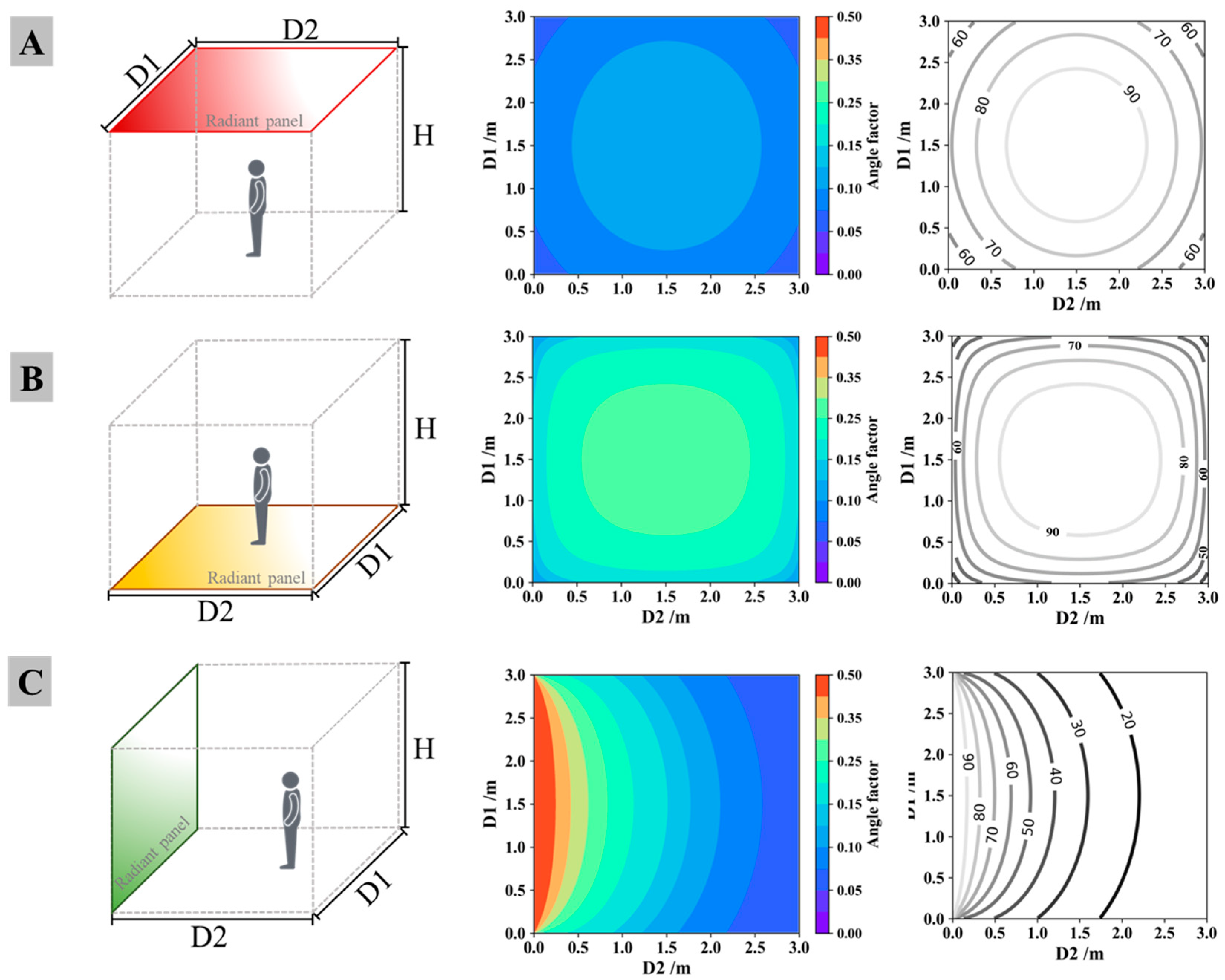
3.4. Distribution of Angle Factors for the Standing Human Body Model

As shown in Figure 10, the distribution of the angle factors between the standing human body model and the radiant panel installed at three different positions was familiar to the sedentary human body model. For the three same-sized radiant panels, the radiant panel placed on the vertical plane could provide the highest angle factor, but the high-angle-factor area was limited, which could also be proved by the contour map of the decay of the angle factor. The angle factor decreased rapidly with the distance away from the radiant panel. Installing the radiant panel on the floor could provide a larger area of high-level angle factor for standing people.
Noting that compared with the sedentary human body model, when the sizes and locations of the radiant panels are fixed, the standing human body would obtain higher angle factors from the ceiling but lower from the floor.

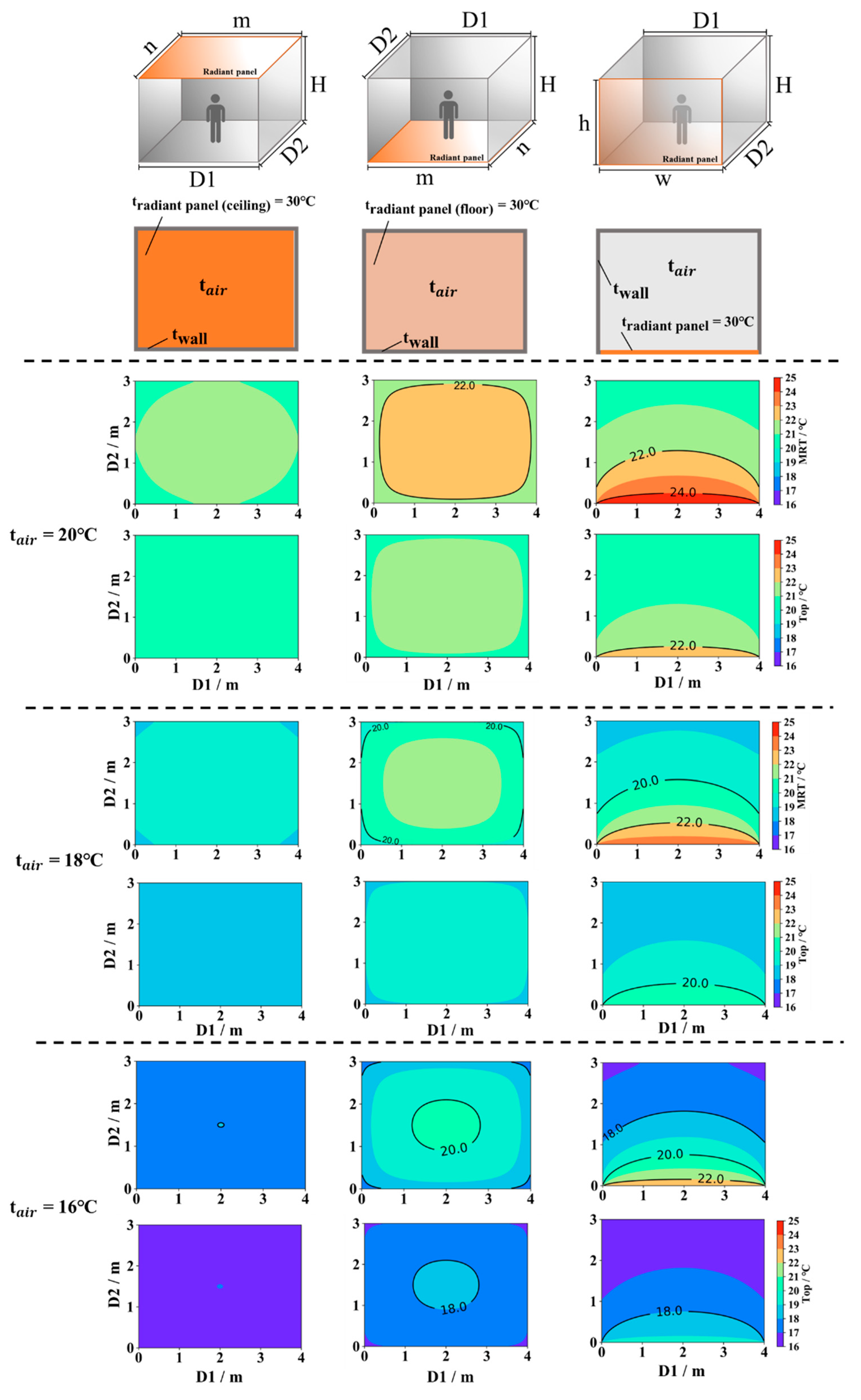
3.5. MRT and Operative Temperature of the Human Body Model

It is supposed that the size of the radiant panel was 3 m × 4 m × 3 m (L × W × H). In the heating system, the temperature of the radiant panel was set to 30 , and the temperatures of the other surfaces were equal to the air temperature. Figure 11 and Figure 12 illustrate the MRT and operative temperature for the sedentary and standing human body models in three different air temperatures: 16, 18, and 20 .
With the help of the HNU Angle Factor Model, it is convenient to compare the efficiency of the radiant system in different air temperatures according to the contour map of the MRT and operative temperature. For heating conditions, if the air temperature was set at 20 , for both sedentary and standing occupancy, the highest MRT was 24 in a very small semicircle area provided by a vertically installed panel. The area of the MRT at 22 could be provided by the panels installed on the floor and vertical surface, but the area above 22 was quite larger when the panel was installed on the floor. The same result was observed for the air temperatures of 16 and 18 . A lower air temperature leads to lower MRTs and operative temperatures.
On the other hand, while the air temperature was set at 18 , all three installations could provide an operative temperature above 18 . During the heating season, an operative temperature above 18 can be a neutral temperature for indoor occupants, noting that the radiant panel installed on the floor could also provide a large area with a neutral thermal environment for occupancy at an air temperature of 16 .
In the cooling system, the temperature of the radiant panel was set to 18 , and the temperatures of the other surfaces were equal to the air temperature. Figure 13 and Figure 14 illustrate the MRT and operative temperature for the sedentary and standing human body models in three different air temperatures, 24, 26, and 28 , with an assumed relative humidity of 60%.
When the air temperature was set to 24 , for both sedentary and standing occupancies, the highest MRT was 22 in a very small semicircular area provided by the vertically installed panel and a small circle provided by the panel installed on the floor. The area of the MRT of 23 was provided by the panel installed on the floor and vertical surface, but the area under 23 was larger when the panel was installed on the floor. The same result was observed for the air temperatures of 26 and 28 . A higher air temperature leads to a higher MRT and operative temperature.
While the air temperature was set at 26 , all three installations provided an operative temperature under 26 . In cooling seasons, an operative temperature above 26 could be a neutral temperature for indoor occupants in China, noting that the radiant panel installed on the floor could also provide a large area with a neutral thermal environment for occupancy at an air temperature of 28 .

4. Discussion

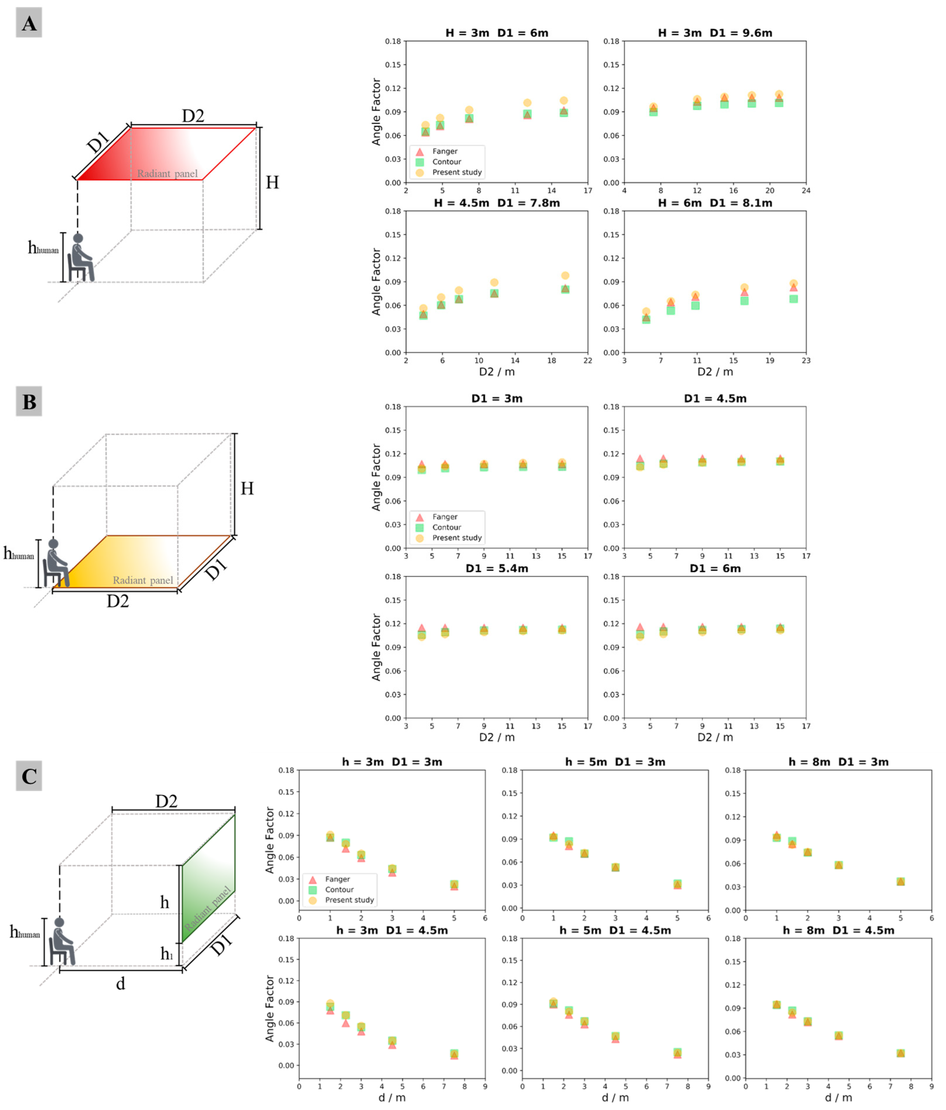
4.1. Comparison among Fanger Diagrams, Contour Integral Methods, and HNU Angle Factor Model

This study presents a novel model that calculates the angle factor between a human body and a radiant panel at a certain location for calculating the radiant heat transfer of the human body. The model was developed by considering the relative geometry and spatial relationship between the human body model and the designed radiant panel. In practical engineering applications, the proposed model offers the advantage of rapidly obtaining the angle factor without complex mathematical methods or numerical simulations. Also, it is important to note that each method for calculating the angle factor between the human body and the radiant panel has its own unique features and specific applications. The researchers should consider the accuracies of these methods before utilizing them in their applications [29]. The contour integral method is particularly suitable for users with strong mathematical skills. Numerical simulation software, like ANSYS [30,31,32], RADIANCE [10], TRANSYS [33], and other business software [34], is well suited for complex calculations that involve the analysis of flow fields and other numerical aspects. Fanger’s diagrams, on the other hand, are useful for quick verification and situations involving a small number of calculations. The HNU Angle Factor Model, as mentioned in this paper, is much easier to be used and friendlier for people who are not familiar with mathematical methods or numerical simulations. Also, because of the simplified calculation procedure, the HNU Angle Factor Model is much faster than mathematical methods, Fanger’s diagrams, and numerical simulations when calculating the angle factor, MRT, and operative temperature for a whole area. For calculating the angle factor at one specific position using a computer, without considering the modeling and condition settings, the ANSYS (Fluent S2S model) needs approximately 1 min, and the angle factor calculating software Anglefactor (V2.0) needs approximately 1 s. While, at the same time, the HNU Angle Factor Model needs only approximately 0.00202 s (the average run time out of 10,000 calculations) for calculating one specific position, 7.61266 s for the MRT distribution of a 300 × 400 grid example, and 5.32115 s for the operative temperature distribution, tested using a laptop equipped with an Intel® Core™ i7-6500U, CPU 2.50 GHz, Windows 10, 64 bit, 8 G RAM.

4.2. Potential Applications of the HNU Angle Factor Model

The development of the HNU Angle Factor Model, a novel approach to calculating human-body angle factors, could contribute to the advancement in the study of radiant thermal environments. The most significant contribution of the HNU Angle Factor Model is that it can provide the distribution of the angle factor and MRT for a human body without using complex mathematical calculations and professional numerical simulation software. It also allows designers to compare the efficiency from the perspective of the heat transfer between a human body with different parameters or settings of the radiant system, including the size, installed location, and temperatures settings for the radiant panel and indoor air. In previous studies, some researchers have tried to obtain the distribution of the MRT [35,36], operative temperature [37], predicted mean vote (PMV) [38,39], and predicted percentage of dissatisfied (PPD) [17,20]. Because the calculation process for a numerical simulation is tedious and time-consuming, researchers have had to repeat the modeling and simulation to find efficient and comfortable radiant system and setting temperatures [40], which might cause energy waste and thermal discomfort. Although a radiant panel system can create a more comfortable environment for occupancy with less energy consumption [41], an unproper design may lead to uncomfortable and nonuniform environments [42]. In addition, some researchers have suggested that combining personal comfort systems (PCS) with radiant systems can be beneficial for both energy consumption and thermal comfort [43]. Therefore, a reliable and convenient radiant system evaluation tool could contribute to energy savings and a comfortable building environment.
Some researchers have found that in winters with severe cold periods, the low surface temperatures of exterior building elements (both opaque and transparent) can easily cause cold radiation into indoor environments and lead to the local discomfort of inhabitants [19,44] and extra heating loads. Thus, this effect caused by exterior building elements should be discussed, even though situations with other envelopes, such as exterior windows and walls, are not mentioned in this study. According to the property of the angle factor, a surface with windows or doors can be calculated by assuming that the total amount of the angle factor is equal to one. In addition, the HNU Angle Factor Model offers a convenient tool for quickly calculating the angle factor, allowing designers to compare the effects of different installation positions on the human body when the radiant panel sizes are fixed, with the effects of varying radiant panel sizes on the human body when the installation positions are fixed. The calculation process of the HNU Angle Factor Model does not require the use of professional complex software or advanced mathematical skills, making it accessible to a wide range of users. Because the HNU Angle Factor Model was coded in Python, it is able to be inserted into other simulation software for wide application, and, at the same time, the proposed model can help designers assess the effect of solar radiation on radiant cooling/heating systems without complex simulations.
On the other hand, the HNU Angle Factor Model can be applied to evaluate the thermal radiation risk under extreme working conditions, such as factories in the iron and steel industry, in which the intense thermal radiation from a steel furnace might put workers in danger. Hence, the HNU Angle Factor Model can be directly applied to analyze the thermal radiation around workers in workplaces with intense thermal radiation to prevent the occurrence of security accidents.
Thus, the HNU Angle Factor Model proposed in this study may contribute to (1) the calculation of the cooling/heating loads of radiant systems; (2) the installation and size of radiant panels; (3) the setting of temperatures of radiant panels and indoor environments; (4) assessment of thermal radiation levels of workers exposed to working environments (outdoor and indoor) with intense thermal radiation; (5) assessment of the effect of solar radiation on radiant cooling/heating systems by designers without complex simulations.

4.3. Limitations

Yet there are still some limitations of the present study. In practical applications, there might be some objects interposed between the human body and a radiant panel. Additionally, in this paper, the calculated area was set as a rectangle, and areas with complex shapes were not mentioned. The radiant heat transfer between a certain human body and radiant panels is largely affected by other indoor objects [21] or complex shapes of rooms [28]. In addition, some researchers have suggested that solar radiation through windows may affect the results related to the MRT [45,46] and thermal comfort [47,48], which was not mentioned in this study. In further research and investigation, situations in which objects interpose, areas have complex shapes, and the effect of solar radiance should be addressed to enlarge the application of the HNU Angle Factor Model. On the other hand, the differences between the results of the HNU Angle Factor Model and other calculation methods might be caused by the human model applied to develop the calculation methods. In the HNU Angle Factor Model, the human body was simplified into a cuboid, and further analysis of the differences with an actual human body is needed.
In terms of the accuracy, the current research phase has demonstrated that the model’s accuracy is deemed acceptable for practical engineering purposes. Further research and investigation will be conducted to address and improve the accuracy of the model to enhance its precision and reliability.

5. Conclusions

In this study, a novel model for calculating human-body angle factors in radiant heat transfer was built. The results were compared with those calculated using the Fanger’s chart and contour integral methods. The main conclusions are summarized below.
A novel angle factor calculation model for the human body, the HNU Angle Factor Model, was built based on the relative space and geometry relationship between the human body and the radiant panel.
The calculated angle factors using the HNU Angle Factor Model were close to the results obtained using Fanger diagrams and the contour integral method. The average relative differences for the present study and the other two methods among 140 cases were 8.1% and 10.0%, respectively.
When the sizes of radiant panels are fixed, placing a radiant panel on the floor might help to create an even and high-efficiency thermal environment for both seated people and standing people.
The HNU Angle Factor Model can be applied to obtain the distribution of the angle factor and the MRT for a human body without complex mathematical calculations and professional CFD software.
The HNU Angle Factor Model needs only about 0.00202 s (the average run time out of 10,000 calculations) for the calculation of one specific position, 7.61266 s for the MRT distribution of a 300 × 400 grid example, and 5.32115 s for the operative temperature distribution.
In conclusion, with some unique advantages, the HNU Angle Factor Model proposed in this study can provide a quick but accurate method to obtain angle factors, which may contribute to the design of radiant cooling/heating systems and the fast assessment of the thermal radiation levels of workers exposed to working environments (outdoor and indoor) with intense thermal radiation. In further application, the HNU Angle Factor Model can help both in terms of savings on energy consumption and in ensuring the safety of workers in intense radiant environments.

Supplementary Materials

The following supporting information can be downloaded at: https://www.mdpi.com/article/10.3390/buildings14020366/s1, File S1: Human body vs. horizontal plane; File S2: Human body vs. vertical plane.

Author Contributions

All authors contributed to the study’s conception. Project administration and supervision were performed by N.L. Formal analysis and development of the methodology were conducted by Y.H. Data collection and analysis were performed by Y.C. The first draft of the manuscript was written by Y.C., and all authors commented on previous versions of the manuscript. All authors have read and agreed to the published version of the manuscript.

Funding

This work was supported by the National Natural Science Foundation of China (No. 52278105 and 52308092).

Data Availability Statement

The data presented in this study are available in Files S1 and S2.

Conflicts of Interest

The authors declare no conflicts of interest.

Nomenclature

βAltitude angle between camera and subject in Fanger’s method (degree)
αAzimuth angle between camera and subject in Fanger’s method (degree)
A2Assumed sphere for surrounding faces of a subject
ApA person’s projected area on a plane perpendicular to the direction of a surface element (dA2) with the angle coordinates (α, β)
AeffEffective radiation area of the subject
MRT Mean   radiant   temperature   ( )
θ h Angle for the side direction of the human body model using the HNU Angle Factor Model
θ v Angle for the front direction of the human body model using the HNU Angle Factor Model
F A - P Angle factor, the ratio of the radiant heat transfer area to the whole space around the human body or body part
i Surface area coefficient of a body part
Top Operative   temperature   ( )
CFD Computational fluid dynamics
PMV Predicted mean vote
PPD Predicted percentage of dissatisfied
PCSs Personal comfort systems

References

  1. Karmann, C.; Schiavon, S.; Bauman, F. Thermal comfort in buildings using radiant vs. all-air systems: A critical literature review. Build. Environ. 2017, 111, 123–131. [Google Scholar] [CrossRef]
  2. Wang, Z.; Ning, H.; Ji, Y.; Hou, J.; He, Y. Human thermal physiological and psychological responses under different heating environments. J. Therm. Biol. 2015, 52, 177–186. [Google Scholar] [CrossRef]
  3. Zhang, F.; Guo, H.A.; Liu, Z.; Zhang, G. A critical review of the research about radiant cooling systems in China. Energy Build. 2021, 235, 110756. [Google Scholar] [CrossRef]
  4. Peng, P.; Gong, G.; Mei, X.; Liu, J.; Wu, F. Investigation on thermal comfort of air carrying energy radiant air-conditioning system in south-central China. Energy Build. 2019, 182, 51–60. [Google Scholar] [CrossRef]
  5. Tian, Z.; Love, J.A. A field study of occupant thermal comfort and thermal environments with radiant slab cooling. Build. Environ. 2008, 43, 1658–1670. [Google Scholar] [CrossRef]
  6. Jin, W.; Jia, L.; Gao, P.; Wang, Q. The moisture content distribution of a room with radiant ceiling cooling and wall-attached jet system. Build. Simul. 2017, 10, 41–50. [Google Scholar] [CrossRef]
  7. Shen, L.; Tu, Z.; Hu, Q.; Tao, C.; Chen, H. The optimization design and parametric study of thermoelectric radiant cooling and heating panel. Appl. Therm. Eng. 2017, 112, 688–697. [Google Scholar] [CrossRef]
  8. Kilkis, B.I. Cost optimization of a hybrid HVAC system with composite radiant wall panels. Appl. Therm. Eng. 2006, 26, 10–17. [Google Scholar] [CrossRef]
  9. Mohammadzadeh, A.; Kavgic, M. Multivariable optimization of PCM-enhanced radiant floor of a highly glazed study room in cold climates. Build. Simul. 2020, 13, 559–574. [Google Scholar] [CrossRef]
  10. Aviv, D.; Hou, M.; Teitelbaum, E.; Guo, H.; Meggers, F. Simulating Invisible Light: Adapting Lighting and Geometry Models for Radiant Heat Transfer. In Proceedings of the 11th Annual Symposium on Simulation for Architecture and Urban Design, San Diego, CA, USA, 25–27 May 2020. [Google Scholar]
  11. Mohamed, S.; Srinavin, K. Thermal environment effects on construction workers’ productivity. Work Study 2002, 51, 297–302. [Google Scholar] [CrossRef]
  12. ISO 7726:1998; Ergonomics of the Thermal Environment—Instruments for Measuring Physical Quantities. ISO: Geneva, Switzerland, 1998.
  13. Rayson, M.; Wilkinson, D.; Carter, J.; Richmond, V.; Blacker, S.; Bullock, N.; Robertson, I.; Donovan, K.; Graveling, R.; Jones, D. Physiological Assessment of Firefighting in the Built Environment; Optimal Performance Ltd.: Bristol, UK, 2004. [Google Scholar]
  14. Sparrow, E.M. A new and simpler formulation for radiative angle factors. J. Heat Transf. 1963, 85, 81–87. [Google Scholar] [CrossRef]
  15. Zhang, S.; Niu, D.; Lin, Z. Mean radiant temperature calculated based on radiant heat dissipation of human body addressing effect of emissivity of inner surfaces of envelope. Sol. Energy 2022, 246, 14–22. [Google Scholar] [CrossRef]
  16. Zheng, D.; Li, N.; Long, J. Radiant angle factor calculation between human body and radiant panel by contour integral method. HV&AC 2015, 45, 91–96. (In Chineses) [Google Scholar]
  17. La Gennusa, M.; Nucara, A.; Pietrafesa, M.; Rizzo, G.; Scaccianoce, G. Angle factors and projected area factors for comfort analysis of subjects in complex confined enclosures: Analytical relations and experimental results. Indoor Built Environ. 2008, 17, 346–360. [Google Scholar] [CrossRef]
  18. Wang, Y.; Meng, X.; Zhang, L.; Liu, Y.; Long, E. Angle factor calculation for the thermal radiation environment of the human body. Lect. Notes Electr. Eng. 2014, 261, 447–455. [Google Scholar] [CrossRef]
  19. Zmeureanu, R.; Iliescu, S.; Dauce, D.; Jacob, Y. Radiation from cold or warm windows: Computer model development and experimental validation. Build. Environ. 2003, 38, 427–434. [Google Scholar] [CrossRef]
  20. Catalina, T.; Virgone, J.; Kuznik, F. Evaluation of thermal comfort using combined CFD and experimentation study in a test room equipped with a cooling ceiling. Build. Environ. 2009, 44, 1740–1750. [Google Scholar] [CrossRef]
  21. Wang, Y.; Li, N.; Hu, J.; He, Y.; Yongga, A.; Yuan, C.; Wang, M. Influence of the Shade from Other Occupants on the Angle Factor between a Human Body and Radiant Surface in Buildings; no. Ishvac 2019; Springer: Singapore, 2020. [Google Scholar]
  22. Li, Z.; Feng, X.; Chen, W.; Fang, Z. Quantifying the effect of ground view factor and ground temperature on outdoor mean radiant temperature. Sustain. Cities Soc. 2022, 84, 104030. [Google Scholar] [CrossRef]
  23. Fanger, P.O.; Angelius, O.; Kjerulf-Jensen, P. Radiation Data for the Human Body. ASHRAE Trans. 1970, 76, 338–373. [Google Scholar]
  24. Horikoshi, T.; Tsuchikawa, T.; Kobayashi, Y.; Miwa, E.; Kurazumi, Y.; Hirayama, K. The effective radiation area and angle factor between man and a rectangular plane near him. ASHRAE Trans. 1990, 96, 60–66. [Google Scholar]
  25. Kalisperis, L.N.; Steinman, M.; Summers, L.H. Angle Factor Graphs for a Person to Inclined Surfaces; ASHRAE: Peachtree Corners, GA, USA, 1991. [Google Scholar]
  26. Hardy, J.D.; Du Bois, E.F.; Soderstrom, G.F. The Technic of Measuring Radiation and Convection: One Figure. J. Nutr. 1938, 15, 461–475. [Google Scholar] [CrossRef]
  27. Chinese Government. National Physical Monitoring Bulletin. Available online: https://www.gov.cn/guoqing/2023-03/12/content_5745851.htm?eqid=8f0dd38a0000df9900000003646f1961 (accessed on 25 January 2024).
  28. Vorre, M.H.; Jensen, R.L.; Le Dréau, J. Radiation exchange between persons and surfaces for building energy simulations. Energy Build. 2015, 101, 110–121. [Google Scholar] [CrossRef]
  29. Ozbey, M.F.; Turhan, C. A comprehensive comparison and accuracy of different methods to obtain mean radiant temperature in indoor environment. Therm. Sci. Eng. Prog. 2022, 31, 101295. [Google Scholar] [CrossRef]
  30. Guo, H.; Ferrara, M.; Coleman, J.; Loyola, M.; Meggers, F. Simulation and measurement of air temperatures and mean radiant temperatures in a radiantly heated indoor space. Energy 2020, 193, 116369. [Google Scholar] [CrossRef]
  31. Shan, X.; Xu, W.; Lee, Y.K.; Lu, W.Z. Evaluation of thermal environment by coupling CFD analysis and wireless-sensor measurements of a full-scale room with cooling system. Sustain. Cities Soc. 2019, 45, 395–405. [Google Scholar] [CrossRef]
  32. Zhang, C.; Heiselberg, P.K.; Chen, Q.; Pomianowski, M. Numerical analysis of diffuse ceiling ventilation and its integration with a radiant ceiling system. Build. Simul. 2017, 10, 203–218. [Google Scholar] [CrossRef]
  33. Dhamodharan, P.; Ayalur, B.K.; Judefelix, J.; Prabakaran, R.; Kim, S.C. Energy saving potential in radiant cooling system by utilizing air-conditioning condensate: A strategy for green building rating. Appl. Therm. Eng. 2024, 236, 121492. [Google Scholar] [CrossRef]
  34. Echarri Iribarren, V.; Galiano Garrigós, A.L.; González Avilés, B. Cerámica y climatización saludable: Paneles cerámicos radiantes en edificios. Condiciones de confort y demanda energética frente a sistemas convectivos. Inf. Constr. 2016, 68, e161. [Google Scholar] [CrossRef]
  35. Xing, D.; Li, N. Numerical Prediction of Mean Radiant Temperature in Radiant Cooling Indoor Environments. J. Therm. Sci. 2022, 31, 359–369. [Google Scholar] [CrossRef]
  36. Xie, Y.; Ishida, Y.; Hu, J.; Mochida, A. Prediction of mean radiant temperature distribution around a building in hot summer days using optimized multilayer neural network model. Sustain. Cities Soc. 2022, 84, 103995. [Google Scholar] [CrossRef]
  37. Halawa, E.; Van Hoof, J.; Soebarto, V. The impacts of the thermal radiation field on thermal comfort, energy consumption and control—A critical overview. Renew. Sustain. Energy Rev. 2014, 37, 907–918. [Google Scholar] [CrossRef]
  38. Ghaddar, N.; Salam, M.; Ghali, K. Steady Thermal Comfort by Radiant Heat Transfer: The Impact of the Heater Position. Heat Transf. Eng. 2006, 27, 29–40. [Google Scholar] [CrossRef]
  39. Magni, M.; Campana, J.P.; Ochs, F.; Morini, G.L. Numerical investigation of the influence of heat emitters on the local thermal comfort in a room. Build. Simul. 2019, 12, 395–410. [Google Scholar] [CrossRef]
  40. Huang, C.; Li, N.; Yongga, A.; Huang, L.; Yuan, C.; Wang, Y. Simulation Research on Indoor Environment and Energy Consumption of Multiple Radiant Heating Modes; no. Ishvac 2019; Springer: Singapore, 2020. [Google Scholar]
  41. Imanari, T.; Omori, T.; Bogaki, K. Thermal comfort and energy consumption of the radiant ceiling panel system. Comparison with the conventional all-air system. Energy Build. 1999, 30, 167–175. [Google Scholar] [CrossRef]
  42. Su, X.; Wang, Z.; Xu, Y.; Liu, N. Thermal comfort under asymmetric cold radiant environment at different exposure distances. Build. Environ. 2020, 178, 106961. [Google Scholar] [CrossRef]
  43. Zhang, H.; Arens, E.; Taub, M.; Dickerhoff, D.; Bauman, F.; Fountain, M.; Pasut, W.; Fannon, D.; Zhai, Y.; Pigman, M. Using footwarmers in offices for thermal comfort and energy savings. Energy Build. 2015, 104, 233–243. [Google Scholar] [CrossRef]
  44. Su, X.; Wang, Z.; Yang, Y. Field study of cold radiant asymmetry caused by exterior built elements of educational buildings in severe cold area, China. Energy Build. 2021, 252, 111401. [Google Scholar] [CrossRef]
  45. Yongga, A.; Li, N.; He, Y.; Yuan, C.; Zhou, L.; Lu, J. Occupant-centered evaluation on indoor environments and energy savings of radiant cooling systems with high-intensity solar radiation. Sol. Energy 2022, 242, 30–44. [Google Scholar] [CrossRef]
  46. Zheng, J.; Yu, T.; Lei, B.; Chen, C. Experimental study on the thermal performance of radiant floor heating system with the influence of solar radiation on the local floor surface. Indoor Built Environ. 2023, 32, 977–991. [Google Scholar] [CrossRef]
  47. Arens, E.; Hoyt, T.; Zhou, X.; Huang, L.; Zhang, H.; Schiavon, S. Modeling the comfort effects of short-wave solar radiation indoors. Build. Environ. 2015, 88, 3–9. [Google Scholar] [CrossRef]
  48. Li, T.; Merabtine, A.; Lachi, M.; Bennacer, R.; Kauffmann, J. Experimental study on the effects of a moving sun patch on heating radiant slabs: The issue of occupants’ thermal comfort. Sol. Energy 2023, 255, 36–49. [Google Scholar] [CrossRef]
Figure 1. (A) Experimental apparatus; (B) notation pertinent to the evaluation of the angle factor between a person (center at P and facing toward the center of the coordinate system) and a rectangle in the x–z plane.
Buildings 14 00366 g001
Figure 2. The diagram of the angle factor, as suggested by Fanger.
Buildings 14 00366 g002
Figure 3. Notation pertinent to the evaluation of the angle factor between a human body and a finite surface.
Buildings 14 00366 g003
Figure 4. Algorithm for calculating the angle factor between the human body and a radiant surface.
Buildings 14 00366 g004
Figure 5. Parameters of the angle factor between horizontal planes and the human body: (A) front view and (B) side view of a panel installed on the ceiling; (C) front view and (D) side view of a panel installed on the floor.
Buildings 14 00366 g005
Figure 6. Parameters of the angle factor between vertical planes and the human body: (A) horizontal view; (B) vertical view.
Buildings 14 00366 g006
Figure 7. The results for the angle factors of the seated human body using the HNU Angle Factor Model and the Fanger and contour integral methods: (A) radiant panel placed on the ceiling; (B) radiant panel placed on the floor; (C) radiant panel placed on a vertical surface. For the seated human body, h1 = 0.6 m.
Buildings 14 00366 g007
Figure 8. The results of the angle factor for a standing human body using the HNU Angle Factor Model, Fanger’s method, and contour integral method: (A) radiant panel placed on the ceiling; (B) radiant panel placed on the floor; (C) radiant panel placed on a vertical surface. For the standing human body, h1 = 1.0 m.
Buildings 14 00366 g008
Figure 9. The distribution and decay of the angle factor for the sedentary human body model: (A) radiant panel placed on the ceiling; (B) radiant panel placed on the floor; (C) radiant panel placed on a vertical surface (H = 3 m, h = 3 m).
Buildings 14 00366 g009
Figure 10. The distribution and decay of the angle factor for the standing human body model: (A) radiant panel placed on the ceiling; (B) radiant panel placed on the floor; (C) radiant panel placed on a vertical surface (H = 3 m, h = 3 m).
Buildings 14 00366 g010
Figure 11. The MRT and operative temperature of the sedentary human body model with different air temperatures of the heating system.
Buildings 14 00366 g011
Figure 12. The MRT and operative temperature of the standing human body model with different air temperatures of the heating system.
Buildings 14 00366 g012
Figure 13. The MRT and operative temperature of the sedentary human body model in different air temperatures of the cooling system.
Buildings 14 00366 g013
Figure 14. The MRT and operative temperature of the standing human body model in different air temperatures of the cooling system.
Buildings 14 00366 g014
Disclaimer/Publisher’s Note: The statements, opinions and data contained in all publications are solely those of the individual author(s) and contributor(s) and not of MDPI and/or the editor(s). MDPI and/or the editor(s) disclaim responsibility for any injury to people or property resulting from any ideas, methods, instructions or products referred to in the content.

