Article

Numerical Simulation and Experimental Study on Construction Forming of Cable-Stayed Tensioned Metal Thin Sheet Structure

1
Hebei Key Laboratory of Civil Engineering Catastrophe Control and Disaster Emergency Response, Langfang 065201, China
2
North China Institute of Science and Technology, Architectural Engineering College, Langfang 065201, China
3
College of Architecture and Civil Engineering, Beijing University of Technology, Beijing 100124, China
*
Author to whom correspondence should be addressed.
Buildings 2024, 14(12), 4059; https://doi.org/10.3390/buildings14124059
Submission received: 22 November 2024 / Revised: 14 December 2024 / Accepted: 18 December 2024 / Published: 20 December 2024
(This article belongs to the Section Building Structures)

Abstract

This study investigates the construction methodology of large-span cable-stayed tensioned metal thin-sheet structures, introducing the “integrated enclosure and load-bearing” design concept. By applying in-plane prestress, the out-of-plane stiffness of the metal thin sheet is effectively enhanced, enabling it to simultaneously serve as an enclosure and a load-bearing component. Through experimental studies and finite element analysis, the study systematically examines the effects of various construction methods on internal forces and displacements. The tensioning of back cables is identified as the safest and most efficient construction method. Subsequently, through simulations of a three-span structure and tensioning forming tests, the research examines displacement, stress, and cable force distribution patterns, demonstrating that increases in the tensioning level result in corresponding increases in sheet surface stress, cable forces, and displacements. The structure exhibits a concave middle section, upward curvatures at both ends, and outward-leaning end columns. Structural members with lower cable forces show minimal impact on displacement and are therefore identified as suitable targets for design optimization. This study offers a theoretical foundation and practical engineering insights to guide the optimization of design and construction for cable-stayed tensioned metal thin-sheet structures.

1. Introduction

With the increasingly severe air pollution and haze situation, open coal storage yards at power plants, ports, coal mines, metallurgy, and coking industries will generate dust when exposed to strong winds, causing significant material losses and polluting the surrounding environment [1]. Temporary and permanent open coal storage yards in the traditional industrial production field are all required to be fully enclosed, so a large number of large-span enclosed engineering projects have been built in recent years [2,3,4,5,6]. However, most of the current enclosed engineering structures are too simple, with the net shell structure and cable-stayed structure accounting for more than 90%. For temporary and permanent coal storage yard engineering structures with spans exceeding 300 m, the net shell structure is no longer suitable, and the economic feasibility of the cable-stayed structure system also becomes increasingly poor as the span increases. Furthermore, the effective utilization rate of the storage space within the yard will drop below 60%. Therefore, it is urgently needed to study a suitable large-span temporary and permanent enclosed coal storage yard engineering structure system with good safety, low cost, short construction period, and strong regional adaptability to meet the high-quality development requirements of environmental protection and low-carbon development.
The pre-stressed steel structure technology has been developed for over half a century and has now entered the stage of extensive application [7]. On the one hand, the number and scale of engineering applications are increasing day by day, and on the other hand, new structural types and new technologies are emerging continuously. The early pre-stressed steel structure technology only introduced pre-stress by adding cables, etc., on the traditional steel structure system to improve the peak internal forces of members or increase the stiffness of the structure, while the later developed whole-span tensioning structure, cable-stayed structure, tensioned cable-membrane structure, and glass curtain wall structure, etc., greatly enriched the architectural forms and reduced the structure weight in large-span structures [8]. Pre-stress technology not only changed the internal force distribution in traditional steel structures but also changed the composition system of traditional structures, thus appearing in a large number of completely different architectural forms, internal force analysis methods, manufacturing processes, and construction technologies [9,10]. Traditional buildings usually use membrane structures, but membrane structures have many unavoidable disadvantages in practical applications, such as low tensile strength and easy damage of the membrane material [11], easy wrinkling, and serious environmental problems [12]. Metal sheet materials have much higher tensile strength and stiffness than membrane material and are more suitable as load-bearing members [12,13]. Under the premise of meeting the basic requirements of comfort and functionality, breaking through the traditional structural system design concept of separating the enclosure structure and load-bearing structure and selecting metal thin sheets with much higher tensile strength and stiffness than the membrane material as the enclosure material is a research trend.
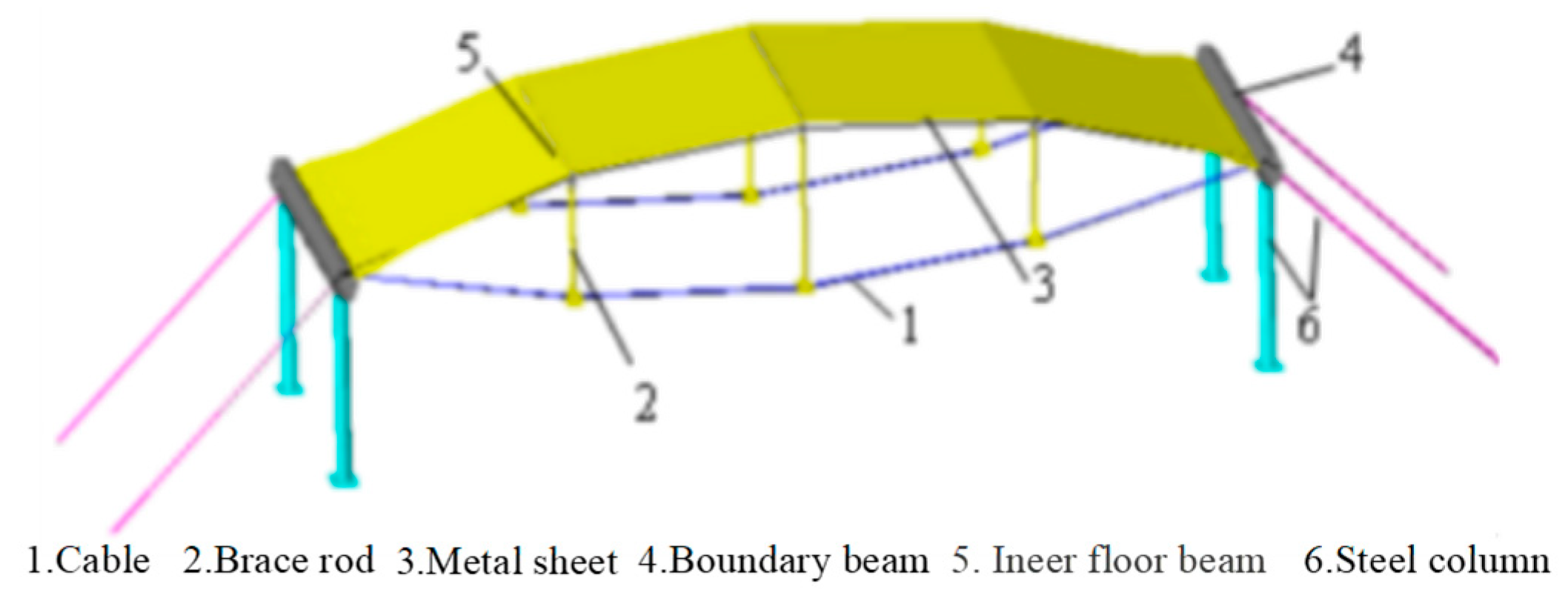
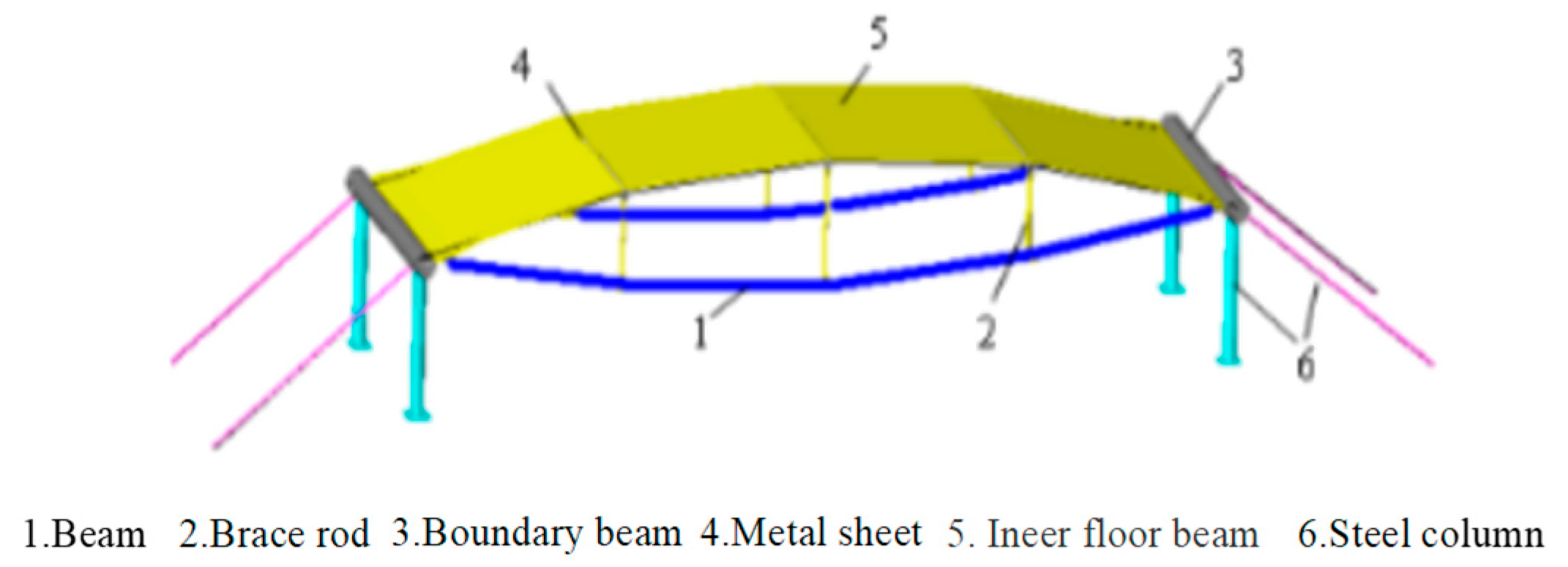
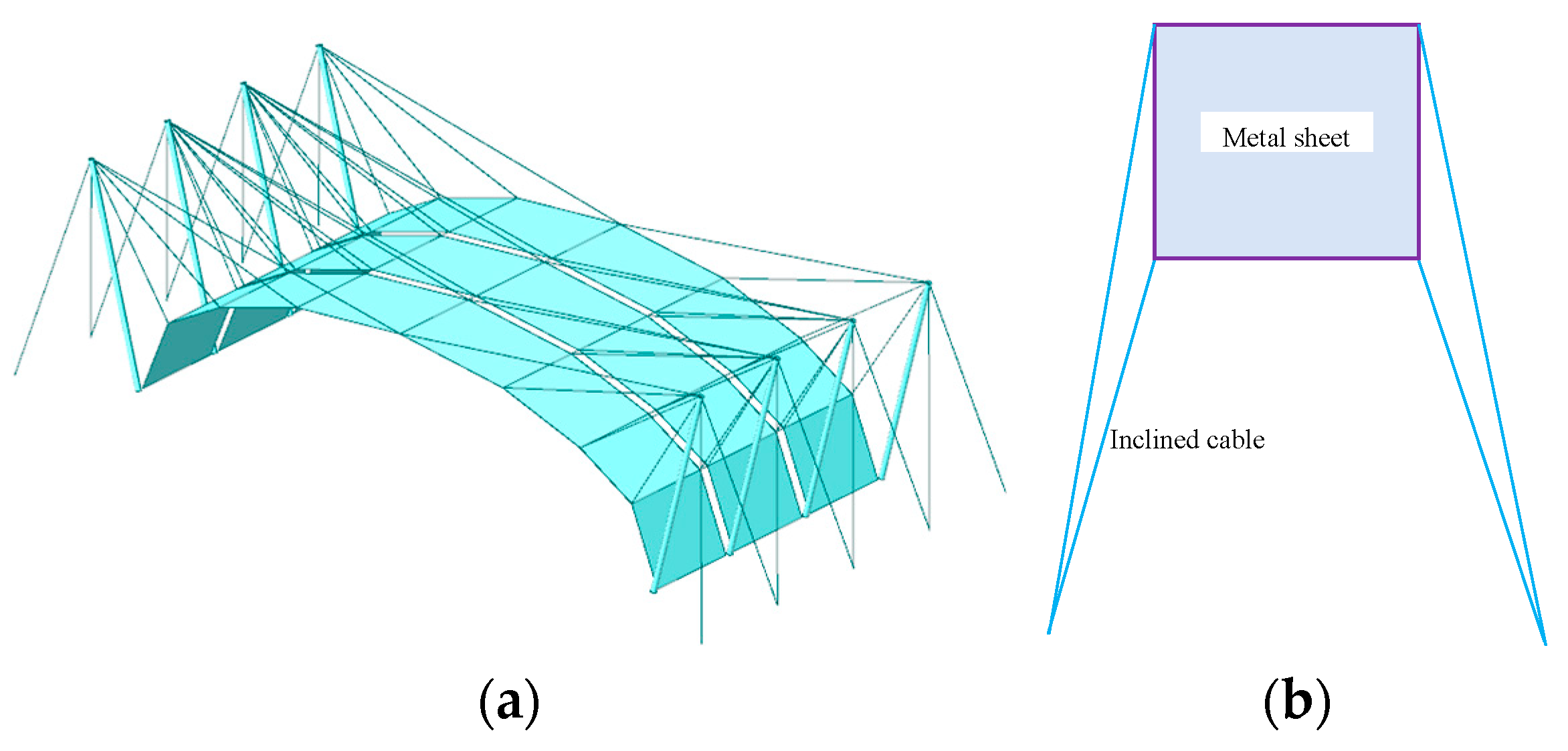
Currently, some research has been conducted on metal roof panel structures; some scholars studied the structural type, joint design, and construction forming methods of the structure system, concluding the following: The structure system was divided into cable-sheet structures (Figure 1) and beam-sheet structures (Figure 2), but such structures are prone to folding. Later, scholars conducted numerical studies on the construction process of cable-sheet structure systems using methods such as tensioned oblique cables, alternating tensioning of longitudinal and oblique cables, direct tensioning of thin sheets, and lifting jacking rods. The above scholars, through their research, have provided assistance for the proposal of the inclined cable-tensioned metal thin sheet structure system, while the three structure systems they proposed share a common core idea: In the structure, both the membrane and the metal thin sheet are tensioned, making them both load-bearing and enclosing members [14].
The inclined cable-stayed tensioned metal sheet structure consists of a steel structural component (steel column), a prestressed cable (inclined cable and back cable), and a metal sheet. The entire structure’s load-bearing system is composed of these three parts, as shown in Figure 3. Among them, the steel structural component mainly serves as a bending and compressive component; the prestressed cable and metal sheet serve as tensile members. Applying prestress to the metal sheet is the key to this structure. Only by applying prestress to the sheet can it have certain stiffness and resistance to external loads, allowing it to span large spans in the roof system, making the inclined cable-stayed metal sheet structure system have better economic performance. There are two ways to apply prestress to the metal sheet: one is to tension the prestress cable, which applies prestress to the metal sheet at the spacing between the sheets; the other is to apply prestress to the metal sheet by adjusting the internal force screws around the sheet. The former is the main means of establishing a large prestress in the sheet, and the latter is an auxiliary means of adjusting the internal stress distribution of the sheet to make it uniform. The impact of the first method on the overall structure is as follows: The prestress applied by tightening the cables effectively distributes external loads through the tensile forces in the cables. With their high tensile strength, the cables primarily bear tensile forces and efficiently transfer the applied loads to the inclined cable support points of the metal sheet. This ensures simultaneous uplift, reducing localized deformation and mitigating stress concentration. For inclined structures, the cables ensure resistance to gravitational and other external loads, maintaining the structure’s stability against tilting and deformation. However, this method imposes strict requirements on the distribution and positioning of the inclined cables on the metal sheet. If the distribution is unreasonable or the forces are excessively high, the supporting joints and connection areas may experience excessive tension, potentially leading to localized instability.
The impact of the second method on structural performance is as follows: This method offers superior local adjustment capabilities. Bolts primarily function by altering the fastening force at connection points to adjust the localized forces within the structure. By modifying the tightening force of the bolts, the load distribution at specific joints can be finely tuned, giving this method an advantage in precisely adjusting stiffness and force distribution. It is particularly suitable for designs requiring fine-tuned mechanical performance optimization. However, the adjustment levels are limited during each iteration, often requiring multi-stage adjustments. Furthermore, its performance is closely related to the distribution and number of inclined cables, which must be carefully designed to ensure structural efficiency.
Given that the structural concept is already well-defined, the selection of materials for each component is critically important. In the field of material mechanical performance research, several studies have explored the properties of different materials. Duan et al. [15] investigated the connection methods between aluminum alloys and high-strength steel, employing a stepped clamping method (SC) to join HC340LA/AA5052-H32. Their study examined the effect of varying forming forces on joint performance, revealing that SC effectively enhances joint strength. The higher the forming force, the more pronounced the advantages of the stepped clamping connection, resulting in improved connection strength. Cheng et al. [16] focused on the laser spiral dissimilar welding of 6082 high-strength aluminum alloy and DP980 high-strength dual-phase steel, analyzing the relationships among weld quality, influencing factors, microstructure, and mechanical properties. Their research emphasized the fatigue performance and fracture mechanism of 6082-DP980 dissimilar metal-welded joints. Ritapure et al. [17] reviewed and experimentally studied the mechanical and tribological properties of zinc-aluminum (ZA) and aluminum-zinc alloys. They found that the Al-25Zn alloy exhibited the highest hardness, tensile strength, and wear resistance while also achieving the lowest coefficient of friction (COF). Additionally, other scholars have analyzed the mechanical performance of various materials in grid-shell structures [18,19], identifying the differences between aluminum alloys and traditional steel structures. Their findings suggest that aluminum alloys, with their lightweight and high-strength properties, have the potential to replace traditional steel in construction, maximizing their advantages in architectural applications.
For metal thin sheet structures, there has been extensive research on the performance of thin sheets and their connections. In the field of metal thin sheet research, Zhang et al. [20] conducted uniaxial tensile tests on copper thin sheets at low temperatures. The test results showed that the higher the temperature, the lower the strength and ductility of the specimen. Wang et al. [21] conducted bulging tests on metal thin sheets with different ellipticities. The test results showed that the principal stress ratio at the apex of the circular bulging test was always 1, while the principal stress ratio at the apex of the elliptical bulging test was always greater than 1, and in an unstable state; the greater the ellipticity, the more obvious the fluctuation in the principal stress ratio. Zhu et al. [22] conducted three-point bending tests on aluminum alloy sheets at different aging times. The test results showed that as the aging time increased, the material’s strength, neutral axis deflection angle, and rebound angle increased, while the circular bending radius and bending thickness decreased. Li et al. [23] conducted mechanical tests on aluminum alloy thin sheets of different solidification temperatures. The test results showed that as the solidification temperature increased, the yield strength and tensile strength of the thin sheet showed a trend of first increasing and then decreasing. Du et al. [24] conducted research on the 7075 aluminum alloy plate, analyzed its mechanical properties, and compared its mechanical properties with those of traditional metal plates. Li et al. [25] studied the compressive buckling behavior of aluminum alloy plates of different sizes and obtained nonlinear buckling loads with different initial geometric defects. Zhang et al. [26] conducted tensile tests on a 5083 aluminum alloy plate at different temperatures to qualitatively analyze the fracture forms and basic laws of fracture. Han et al. [27] used arc additive manufacturing technology to manufacture 2319 aluminum alloy parts. Through electrochemical tests and local corrosion tests, the corrosion performance of additively manufactured 2319 aluminum alloy and 2219 aluminum alloy thin plates was systematically studied. From the current research and engineering practice, the material for metal thin sheet structures has gradually shifted to aluminum alloy. Aluminum alloy, with its excellent strength, lightweight, and corrosion resistance, has become the main choice for metal thin plate structures. In the existing research, various experimental results have further confirmed the superiority of aluminum alloy thin plates in practical applications.
In metal sheet connection, Wahyudianto et al. [28] found that it is difficult to obtain the best results by traditional welding methods when welding aluminum alloy. The stirring friction welding process can effectively solve this problem, but the drill speed must be controlled. When the speed is changed from 900 rpm to 2280 rpm, the material quality distribution becomes more uniform, and the joint hardness and tensile strength are improved. Song et al. [29] found that after stirring friction butt welding a 6 mm thick TC17 titanium alloy sheet, the fine-grained beta phase does not precipitate secondary meta-stable organization, and a softer welding zone is formed, which is beneficial to the ductility of the welded parts. Chaudhari et al. [30] found that as the welding speed decreased, the average grain size of the two phases increased with the decrease in the lateral speed, leading to an increase in plastic deformation. Additionally, some scholars have conducted research on the mechanical properties of large-span cable net structures and proposed that cables can have better load-bearing capacity and can be used in large-span structures [31,32,33].
Based on the above research, cable-stayed tensioned metal thin sheet structures combine the advantages of high strength, lightweight properties, high rigidity, and minimal deformation. By introducing prestress, the out-of-plane stiffness of the metal sheets is significantly enhanced, enabling effective resistance to wind and snow loads. At the same time, these structures integrate both enclosure and load-bearing functions, improving material utilization and economic efficiency. Their ease of construction and durability result in reduced maintenance requirements. Compared to inflated membrane structures, inclined cable-tensioned metal sheet structures offer greater stiffness, superior durability, and better stability as they do not rely on continuous air supply. Compared to cable-net structures, they provide more uniform force distribution, avoiding issues of local stress concentration. Compared to tensegrity structures, they feature lower construction complexity while fulfilling both load-bearing and enclosure requirements. Finally, compared to grid-shell structures, they are lighter in weight and involve lower construction costs while maintaining comparable load-bearing capacity and stability. Overall, inclined cable-tensioned metal sheet structures excel in stability, economic efficiency, and multi-functionality, making them an ideal choice for large-span buildings, particularly for both temporary and permanent applications. In terms of material selection for the metal sheets, aluminum alloy demonstrates significant advantages over traditional steel. First, aluminum alloy has a density of only about one-third that of steel, which substantially reduces the self-weight of the structure while meeting strength requirements, making it particularly suitable for large-span buildings and engineering applications requiring lightweight materials. Second, aluminum alloy offers excellent corrosion resistance, as its naturally forming oxide layer effectively protects against atmospheric and chemical corrosion, thereby lowering maintenance costs over the long term. Additionally, aluminum alloy has superior ductility and process ability, allowing it to be easily fabricated into complex shapes through extrusion, casting, and welding, meeting diverse engineering design needs. Furthermore, aluminum alloy provides high-quality surface finishes, enabling advanced aesthetic treatments that enhance the appearance and durability of the structure.
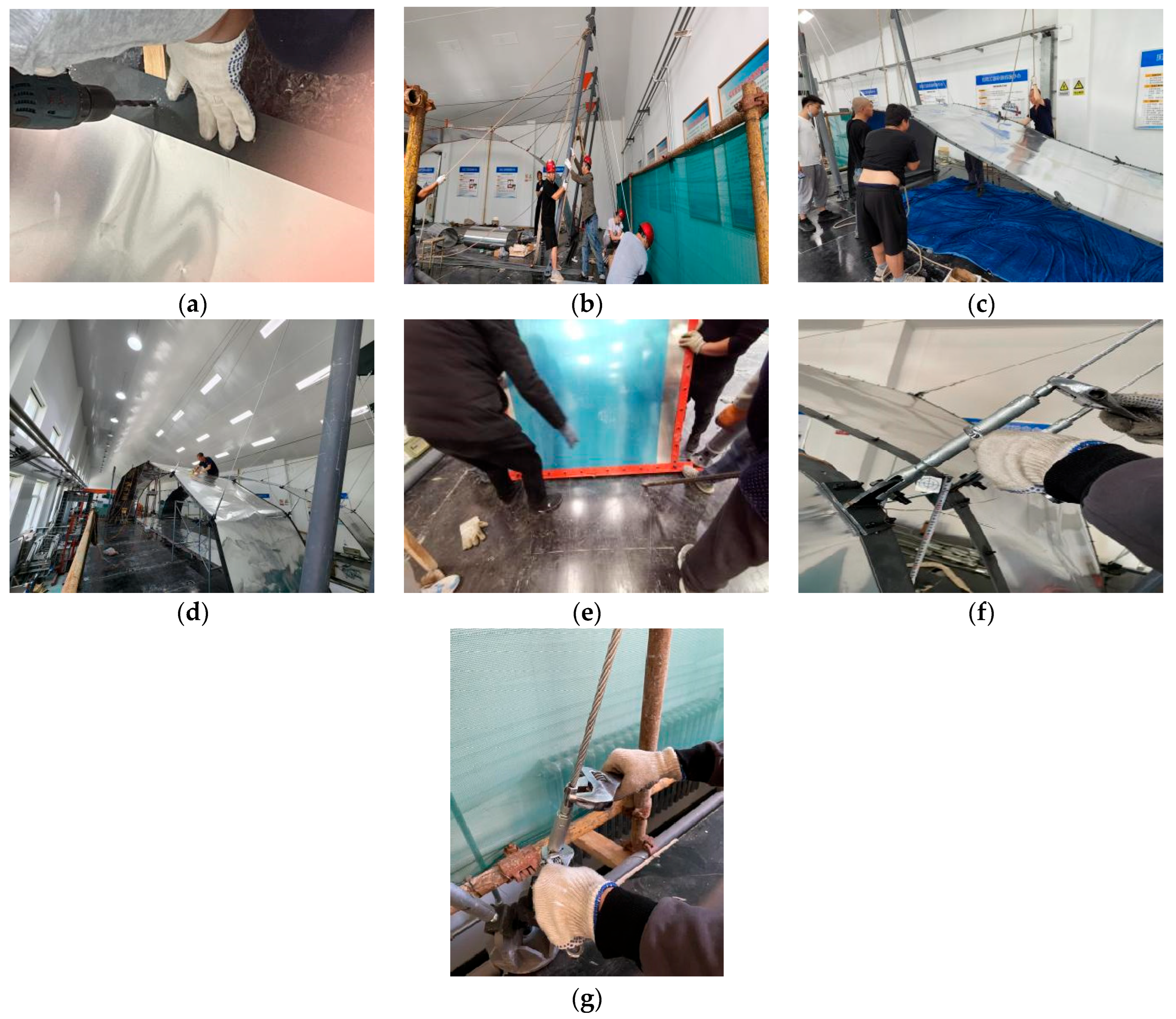
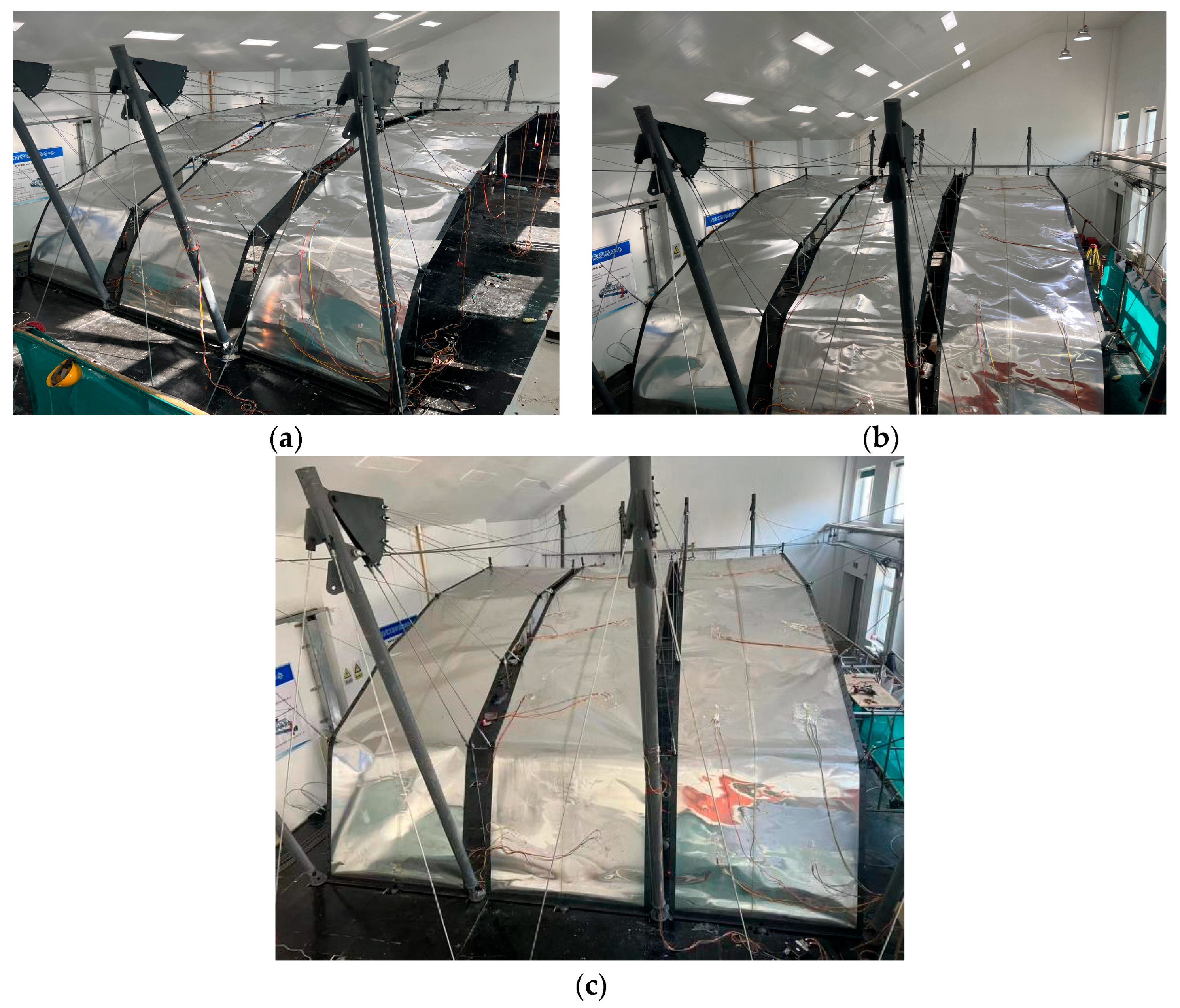
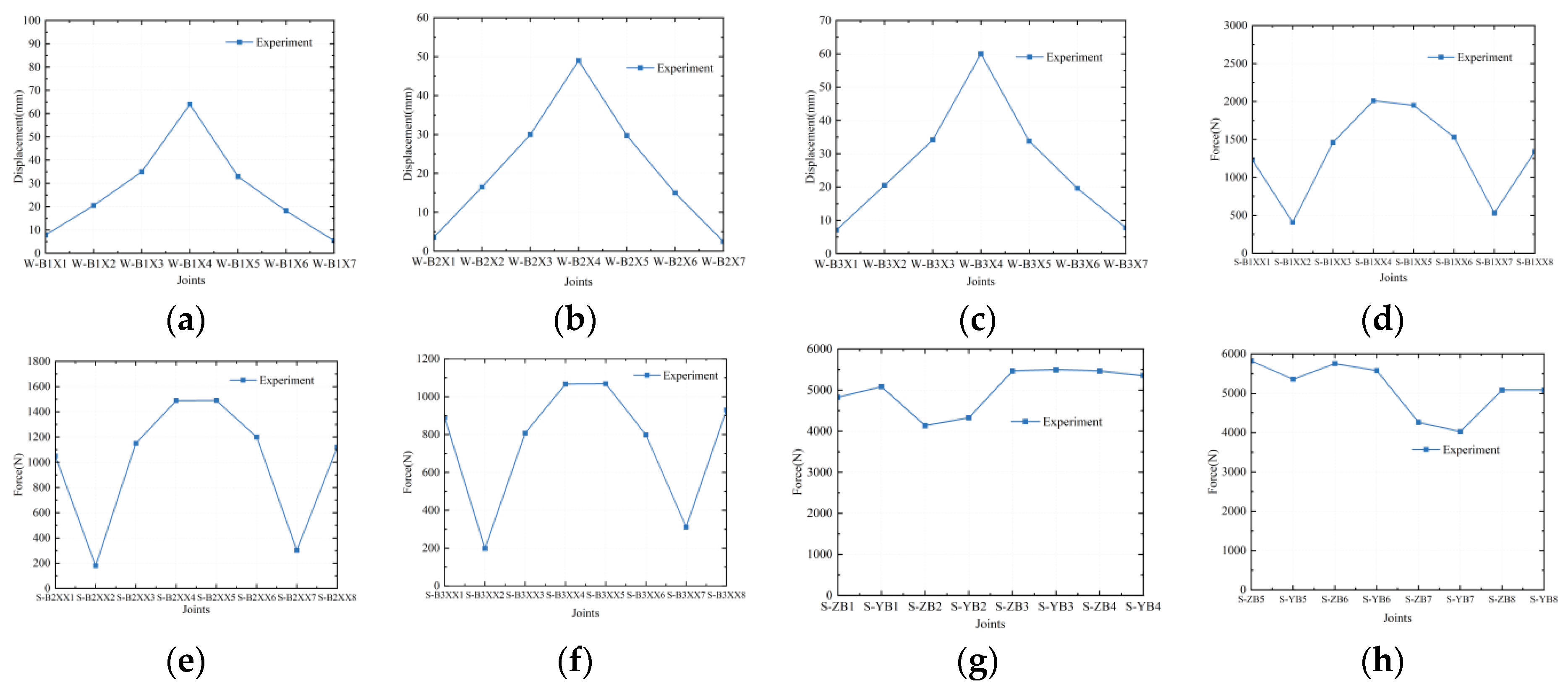
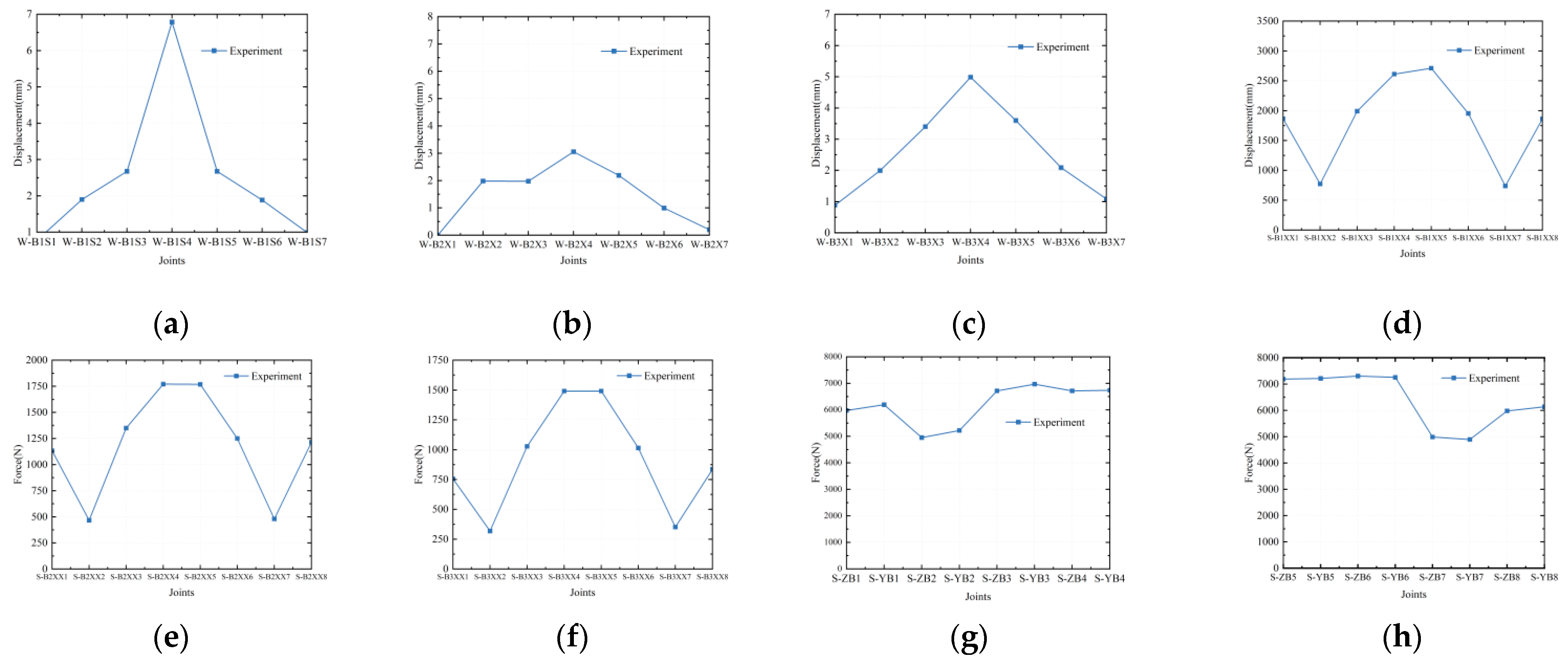
Therefore, this study proposes the use of aluminum alloy for the tensioned metal sheet structures. Given the significant number of prestressed members in such structures, the tensioning and shaping processes of these components directly determine the efficiency and safety of the construction. These processes also play a critical role in achieving the desired internal forces and displacement variations during tensioning. This study uses a real-world metal sheet structure project with dimensions of 120 m × 60 m × 30 m as a case study and proposes multiple feasible construction methods tailored to cantilevered tensioned metal thin sheet structure systems. Various construction methods specific to this structural system are examined, and the most effective forming technique is identified. A 1:10 scaled prototype model composed of three trusses is subsequently developed and subjected to tensioning tests using the back-cable tensioning construction method, enabling an investigation into the changes in internal forces and displacements throughout the forming process. Finite element simulations are also performed to elucidate the evolution, mechanisms, and trends of internal forces during the forming process, providing a theoretical foundation for the design, analysis, and practical engineering applications of these structural systems.

2. Optimization and Selection of Structural Construction Forming Method

2.1. Construction Forming Method

The structure consists of inclined cable, back cable, metal thin sheets, and steel columns. The back cables of the structure are connected to the ground, and the force generated by tension is transmitted to the ground through the back cable, thereby forming a stable structure. The inclined cable, back cable, steel columns, and metal sheets in the same plane are defined as one unit. When the structure has a large span and length, it is composed of several elements. Since there are more inclined cables in the structure, the study of the construction method will become more important. The correctness or incorrectness of the construction method directly affects the final shape of the structure. Based on the construction forming methods of the pre-stressed structure system that has been studied and matured, the following construction forming methods are proposed for the cable-stayed tensioned metal sheet structure in this study.

2.1.1. The Tensile Back Cable Method (SG1)

When the structure is longer in length, it will be composed of several spans of elements. In this case, the more ideal method of tensioning is as follows: First, the cables are installed and adjusted according to the finite element calculated length, and then the back cables of several spans of elements are tensioned simultaneously. However, in reality, there may be a shortage of tensioning equipment. Therefore, the odd and even tensioning method or the grouping and grading tensioning method is adopted. The odd and even tensioning method is to number all the back cables, then divide the odd-numbered cables and even-numbered cables into different tensioning groups. After grouping, tensioning is carried out. In order to ensure the synchronicity of the tensioning process, the tensioning operation is divided into multiple steps, and the odd and even cables are tensioned separately. Finally, the structure reaches the desired shape. The advantage of this method is that the operation platform is placed on the ground, making it convenient to operate and easy to construct.

2.1.2. The Tensile Inclined Cable Method (SG2)

The tensile inclined cable method is to install and adjust the back cable according to the calculated length of the finite element and then stretch the back cable of several elements at the same time. It is also divided into odd and even tensioning or group-grading tensioning; the steps are the same as the tensioning back cable method. The disadvantage of this method is that in actual engineering, the height of the structure is relatively high, and when using this method, the tension equipment needs to be moved to the position of the cable node, and the operating plane is high, which is not very convenient.

2.1.3. The Method of Lifting Steel Columns Method (SG3)

The method of lifting steel columns involves using specific lifting equipment, such as jack stands, to raise the height of steel columns, thereby causing the tension in the cables and the metal sheets to be applied and ultimately transferring the force through the back cables to the ground. The disadvantage is that it requires specific lifting equipment and has higher requirements.

2.1.4. The Direct Tensioning Thin Sheets Method (SG4)

The direct tensioning thin sheets method is proposed based on the characteristics of membrane structure tensioning and shaping. It is achieved by directly tensioning the membrane material, but the prerequisites for this method are two: first, due to the low elastic modulus of the membrane material, the tensioning of the membrane material can be achieved by adjusting the boundary conditions. However, for membrane structure, the elastic modulus and stiffness of metal thin sheets are larger, and the tensioning of metal thin sheets requires a suitable tensioning conversion device that can withstand large forces. Second, a tensioning device that is compatible with the structure is also needed, which requires the ability to apply the required force. The advantage of this method is that the metal thin sheet is tensioned more directly and evenly, but the disadvantage is that it requires specific tensioning devices and boundary adjustments, with higher requirements.

2.2. Comparison of Results of Construction Forming Methods

2.2.1. Model Establishment

The overall structure consists of a metal thin sheet, cable, and steel columns with a span of 12 m and a depth of 1.5 m. The slant height f is 3 m, the slant-span ratio is 1/4, and the sheet thickness t is 1 mm. There are 4 steel columns, each 4.2 m high, and they are inclined towards the Y direction by 1.1 mm. There are 4 back cables, inclined towards the Y direction by 0.9 m. There are 16 inclined cables at the top of the metal thin sheet. See Figure 4 and Table 1 for details, and refer to the sheet numbering. To more clearly indicate the names of the various members of the structure, the members of the structure were simplified, and displacements were usually measured at positions where the structure changed significantly, so the displacement points were chosen at the connection points between the sheet and the cable and at the connection points between the cable and the top of the column. The displacement point numbering was determined according to the numbering of the sheets from left to right, from 1 to 7. The notation W-B1X1 means the displacement at the first node on the left of sheet 1, and W-ZZ1 means the displacement of the leftmost column 1. The cable force numbering was determined according to the numbering of the sheets from left to right, from 1 to 8. For example, the leftmost inclined cable on sheet 1 is named S-B1XX1, meaning cable force-inclined cable 1 on sheet 1. The leftmost back cable is named S-ZB1, meaning cable force-left back cable 1.

2.2.2. Selection of Elements and Material Properties

Table 1 shows the key parameters of the materials used in the cable-stayed metal sheet structure, including the material, size, and modulus of elasticity of the steel wire ropes, steel columns, and metal sheets. The background members and the four cable-stayed ropes are made of steel wire ropes with diameters ranging from 9.8 to 18 mm and an elastic modulus of 1.6 × 10⁸ Pa, suitable for high-stiffness demand tension members that can effectively bear and transmit external loads. The steel columns are made of Q345 steel with a cross-section size of 114 × 5 mm and an elastic modulus of 2.06 × 10⁸ Pa, ensuring the stability and load-bearing capacity of the support role in the overall structure. The thin plate part is made of aluminum with a thickness of 1 mm and an elastic modulus of 7 × 10⁷ as a non-load-bearing component, suitable for lightweight construction requirements. The parameter selection in this table reflects the comprehensive consideration of the stiffness, load-bearing capacity, and lightweight of the materials in the cantilevered metal plate structure, providing reliable assurance for the structural mechanical properties and durability. The cables and back cables are made of only tensioned cable elements; the steel columns are made of truss elements; and the plates are made of plate elements. The supports are fixed hinge supports.

2.2.3. Analysis of Result

  • Displacement
There are X, Y, and Z coordinate differences of the four methods in Table 2. Since the structure is an upside-down symmetrical structure, W-B1X1, W-B1X2, W-B1X3, W-B1X4, W-ZZ1, and W-ZZ2 are taken. The state of the structure without prestress, not subjected to external loads, and only subjected to its own weight is called the initial state.
From the X, Y, and Z coordinate differences of each node relative to the initial state in Figure 5, it can be analyzed that the cable-suspended inclined cable method performs best among the four construction forming methods, with the node’s X, Y, and Z coordinates closest to the initial design state, which can accurately restore the designed shape with high precision and is the preferred construction method for large-span structural systems. The top-raised steel column method ranks second, with certain practical value in specific construction scenarios. The geometric deviation between the cable-suspended back cable method and the direct tensioned thin sheet method is relatively large, especially the direct tensioned thin sheet method, whose construction accuracy and shape controllability are significantly limited, showing its limitations. In the direct tensioned thin sheet method, the displacement change in the X direction of the W-B1X1 node is significantly different from that of other methods and presents a different trend, mainly because when a fine-scale model is used, a large deformation occurs in the bottom metal sheet when a Y-direction prestress is applied, and an additional force is generated in the X direction, resulting in a significant increase in the X-direction displacement, further indicating that this method needs to be optimized in terms of stress transfer path and deformation control. Furthermore, the trends of displacement changes in the Y and Z directions for the four methods are generally consistent, reflecting the structural deformation patterns in these directions, and the displacement amplitude differences are mainly influenced by the local stress characteristics and boundary conditions during the construction process. The comprehensive analysis shows that the prestressed inclined cable method has strong geometric shaping control ability, while the direct prestressing of thin sheet method needs to optimize the prestressing loading method or introduce auxiliary equipment to control the additional force to improve its construction effect.
2.
Cable force
Based on the displacement change data, the optimal construction method is the tensioned cable method. Compare the stress conditions of the tensioned cable method with those of the other three construction forming methods in Table 3. Since the structure is symmetrical in both directions, the members selected are S-B1XX1, S-B1XX2, S-B1XX3, S-B1XX4, S-ZB1, and S-ZB2. The comparison is shown in Figure 6. From the analysis of the stress values and stress change values of each element in Figure 6, it can be seen that the influence of different construction forming methods on the stress distribution of the structure is significantly different. The construction method with the stress value closest to that of the tensioned inclined cable method is the top-lifting steel column method, with a difference range of 0–6%, showing high consistency. The smallest difference is located at S-B1XX1, at 1.26%, while the largest difference is at S-B1XX2, at 7.62%. The second best construction method is the tensioned back cable method, with a difference range of 4–10%, showing medium consistency. The smallest difference is located at S-B1XX1, at 14.61%, while the largest difference is at S-B1XX4, at 9.51%. The worst construction method is the direct tensioning of thin sheets method, with a difference range of 25–30% and large fluctuations. The smallest difference is located at S-B1XX2, at 25.77%, while the largest difference is at S-B1XX1, at 28.8%. In terms of stress change stability, the top-lifting steel column method performs best, with stress change values of each element stable within 25 MPa.
However, when employing the tensile inclined cable method, high-altitude tensioning is required, involving a large number of inclined cables that must be tensioned synchronously at both ends of the structure. This process demands substantial equipment support and precise synchronous control. Due to the elevated nature of the operation, construction faces significant safety risks, such as worker falls and equipment malfunctions. For the lifting steel columns method, the process begins with the precise elevation of the steel columns. This is typically achieved by gradually lifting the columns to their designated positions using equipment such as jacks. Since the steel columns are connected to both back cables and inclined cables, the jacking process requires meticulous control over the lifting speed and force to maintain the force balance within the column-cable system. Each support point of the steel column must be adjusted synchronously during the lifting process to prevent imbalanced tension or uneven elevation, which could result in column deformation or structural instability. Additionally, connecting the steel columns to the lower structure presents a significant technical challenge. Once the lifting is complete, ensuring a stable and secure connection between the steel columns and the foundation is critical to maintaining structural stability. Taking into account the construction safety, equipment availability, and operational convenience, the tensioned back cable method is ultimately chosen as the construction analysis method for the suspended cable-stayed metal sheet structure. This choice balances the consistency of stress distribution and the operational feasibility, providing a practical technical solution for optimizing the construction process of large-span metal sheet structures. It also provides scientific references for subsequent research and engineering applications.

3. Tension Forming Test of Multi-Metal Sheet Structure

3.1. Experimental Model

Through Section 2 research on different construction forming methods, the optimal construction forming method for this type of structure was obtained. To verify the effectiveness of this method, experimental studies on the construction tension forming of multiple spans of actual structures were conducted. The entire structure consists of three spans and six trusses, made up of metal thin-sheet structures, cable structures, and steel structures. The span of the metal thin-sheet structure is 12 m, the depth is 1.5 m, the height f is 3 m, the eave height-to-span ratio is 1/4, and the sheet thickness t is 1 mm. There are eight steel columns, with a height of 4.2 m, and they are inclined towards the Y direction by 1.1 mm. There are 16 back cables, inclined towards the Y direction outside by 0.9 m. There are 48 top-mounted inclined cables on the metal thin-sheet structure. All inclined cables are connected to the steel columns at their upper ends and are evenly distributed and connected to the metal sheet at their lower ends, as shown in Figure 7. The inclined cables are spaced at equal intervals along the metal sheet, enabling the uniform transfer of surface loads to the cables. Additionally, to prevent in-plane contraction of the metal sheet, the inclined cables are arranged at an angle between the steel columns and the metal sheet, creating an out-of-plane member to tension and lift the sheet (Figure 7b).

3.2. Experimental Equipment

3.2.1. Strain Measurement Equipment

Strain gauge and the DHDAS dynamic signal acquisition and analysis system were utilized for stress measurement. The strain gauge setup includes strain rosettes oriented at 0°, 90°, and 45°, allowing for multi-directional stress analysis. These strain rosettes were specifically chosen to eliminate the need for on-site tin soldering, significantly reducing the preparation time required for field testing and improving overall work efficiency. The configuration of the strain rosettes is illustrated in Figure 8a.

3.2.2. Cable Force Measurement Equipment

Cable force measurements were conducted using a bow-type force meter and a lateral pressure tension tester. Both equipment employ mechanical sensors to apply a transverse force P perpendicular to the cable, and the internal processors of the equipment calculate the corresponding cable force. These two cable force measurement devices are lightweight, simple in structure, and easy to operate, making them suitable for use in various scenarios. They offer high measurement accuracy with automatic system compensation. When the specifications of the tested cable match the corresponding specifications of the force meter, the accuracy within the rated range can reach within 2%. Additionally, these devices can directly measure cables under tension without requiring disassembly. The cable force measurement equipment is shown in Figure 8b.

3.2.3. Displacement Measurement Equipment

During the construction process of the experimental structure, the primary focus was on monitoring the vertical displacement changes at the connection nodes between the panels and the cables. To ensure the accuracy of the measurements, two methods were employed simultaneously: attaching reflective markers at the joints for total station measurements and hanging measuring tapes at the nodes for level equipment measurements. The results from both methods were compared, and the optimal measurement values were selected for analysis. The total station, equipped with a built-in data processing system, allowed for fast and accurate data processing and storage, eliminating the need for manual recording and minimizing reading errors throughout the measurement process. In contrast, the level equipment, while lacking advanced data processing capabilities, offered the advantages of simplicity, lightweight design, and ease of operation, requiring only basic training for use. The displacement measurement equipment is shown in Figure 8c.

3.3. The Joint Design of Structures

The joint design emphasizes simplicity and efficiency while ensuring compatibility with practical engineering applications, prioritizing ease of construction and safety. In the experimental model, four types of nodes were designed: the connection between the metal sheet and the inclined cables, the connection between the steel column top and the inclined cables, the connection between the steel column and the ground, and the connection between the back cables and the ground. The design process comprehensively considered factors such as the characteristics of the experimental site, the force distribution of each structural component, and the specific requirements for node performance. The detailed node design is illustrated in Figure 9.

3.4. Experimental Process

This section conducts a verification test for the suspended cable metal sheet structure with inclined cables, aiming to verify the structural performance of the structure through a systematic test procedure. The test involves gradually applying prestress to the inclined cables and back cables to precisely adjust them, ensuring the stability and precision of the structure. The experiment not only involves the installation and fixing of various members but also includes detailed steps for tensioning and adjustment to control the structural load state. The following are the specific test steps:
(1) Lay the metal sheet flat on the ground and install the upper and lower clamps according to the design drawing. Drill holes at the designated positions and insert the bolts, but leave them loose for the smooth adjustment process. Meanwhile, install the cable clamps at the locations of the cable nodes (Figure 10a). (2) Install the steel columns and hang the back cables. Adjust the head of the back cables to their maximum travel, secure them with hand-operated hoists on the opposite side, and set up temporary supports to ensure stability during construction (Figure 10b). (3) Fix the back cables. After the steel columns are adjusted to their correct positions, fix the back cables to the ground to form a preliminary stable structural support system (Figure 10c). (4) Install the inclined cables. Connect the inclined cables to the node of the steel column and leave the other end hanging for subsequent installation and adjustment (Figure 10d). (5) Move the metal sheet to its corresponding horizontal projection position to prepare for the hanging operation (Figure 10e). (6) Connect the central node of the metal sheet to the cable stay and hang the cable stay in sequence to the end positions of the metal sheet. (7) Secure the bottom position of the metal sheet to ensure its stability in the vertical direction (Figure 10f). (8) Gradually adjust the length of the inclined cable to reach the calculated design length required for the structure, ensuring the initial stress state of the tensioning system (Figure 10g). (9) Adjust the length of the counter cable to meet the initial length requirement calculated, ensuring the prestress state of the counter cable meets the design standard (Figure 10). (10) Tighten the counter cable nut and fine-tune in stages: first-level adjustment of both end counter cables by 28 mm and central counter cable by 12 mm; second-level adjustment of all by 8 mm; third-level adjustment of all by 12 mm, until the overall structure reaches the expected shape. Adjust the tension using a two-end synchronized tensioning method and record relevant cable force, displacement, and stress data for analysis. After the structure was tensioned and shaped (Figure 11), as shown in the figure, the overall state of the metal plate exhibited high flatness, with a uniform and orderly surface. This demonstrated excellent construction effects. At the same time, the three trusses maintained good symmetry and orderliness in spatial layout and shape, with clear structural lines and rational load-bearing states.

3.5. Analysis of Experimental Results

Through relevant data analysis, the trend of internal forces in the structure under different structural grading loadings was obtained. From the displacement diagrams such as Figure 12, Figure 13 and Figure 14, it can be seen that the displacement distribution of each sheet shows certain regularity under the first level of loading. The maximum displacement is concentrated in the middle of the sheet, showing the characteristic of non-uniform displacement distribution of cantilever sheets. This may be related to the loading position and the tensioning state of the cable. As the loading is gradually increased, the displacement curve tends to stabilize, indicating that the structure has good adaptability to the loading. For the change in cable force, the cable force of the cantilever cable is significantly increased during the gradual loading process, but the change in cable force at different positions exists. This difference may be due to the geometric characteristics of the cantilever structure and the initial tensioning value. The cable force change curve tends to stabilize in the later loading period, reflecting the structure’s self-balancing ability. Figure 12g,h show the difference in cable force between the left and right back cables. In the initial loading stage, the cable force distribution of the two back cables is relatively uniform. However, during the loading process, the cable force of the left back cable shows a greater growth trend than that of the right back cable. This phenomenon may be due to the structural symmetry being affected by construction errors or initial conditions. From the comparison of the results of each level (Figure 12, Figure 13 and Figure 14), it can be seen that the displacement and cable force changes follow a linearly increasing trend with the increase in loading grade. Gradual loading makes the cantilever sheet gradually reach the designed target state and avoids the occurrence of abnormal mechanical phenomena due to sudden loading. The trend of loading change at each level is basically consistent, avoiding the occurrence of sudden changes in internal forces and displacements during the tensioning process. However, the tension forces in the left and right back cables are not entirely identical. This discrepancy indicates that, due to installation and manufacturing errors, the structural forces on the left and right sides are not perfectly symmetrical during the loading process. Ideally, the forces in the back cables should be as uniform as possible to ensure structural symmetry and stability. When there are significant differences in the forces of the left and right back cables, the structure may deviate from its designed symmetrical state, potentially impacting the overall balance of the structure. The tension in the back cables is a critical factor influencing structural stability. If there are differences in the tension between the two sides, localized stress concentrations may occur, which could compromise the structural stability. For instance, if one side’s back cable bears significantly higher tension, it may exert greater pressure on that side’s support or connection points, increasing the risk of localized failure or damage in that region.

4. Numerical Simulation Analysis of Construction Forming Process of Cable-Stayed Tensioned Metal Sheet Structure

Using finite element software to establish a numerical simulation model, conducting numerical simulation analysis of the structure to obtain the internal force and displacement change law of the structure under different graded loading, and comparing the analysis with experiments to verify the validity of numerical simulation. Subsequently, the internal force development change law of the structure during the forming process was analyzed in more detail, systematically revealing the internal force development mechanism of the structure.

4.1. Material Properties Experiment

Material properties experiments were conducted on the members used in the model experiment, focusing primarily on uniaxial tensile experiments for the cables and metal sheets. These tensile experiments provided key static mechanical parameters, such as stress-strain curves and maximum breaking forces, which were used for subsequent data analysis in the model experiment and served as a basis for parameter input in finite element simulations.

4.1.1. Cable

Three cable specimens used in the structural experiment were selected for uniaxial tensile testing. The specifications of the cable specimens are listed in Table 4. Based on the measured data, the stress-strain curves were plotted, as shown in Figure 15a. The elastic modulus and breaking force of the specimens are as follows: Member 1 exhibited an elastic modulus of 1.06 × 10⁵ MPa and a breaking force of 17.89 kN; Member 2 showed an elastic modulus of 8.5 × 10⁴ MPa and a breaking force of 17.34 kN; and Member 3 had an elastic modulus of 1.15 × 10⁵ MPa and a breaking force of 16.08 kN. The average elastic modulus of the cables was calculated to be 1.02 × 10⁵ MPa, and the average breaking force was 17.10 kN. The failure modes of the cable specimens are depicted in Figure 15b.

4.1.2. Metal Sheet

Three metal sheet specimens were subjected to uniaxial tensile testing, all made of 0.6 mm thick aluminum alloy (3003) with a gauge length of 25 mm. The detailed dimensions of the specimens are shown in Figure 16a–c. Based on the measured data, the stress-strain curves were plotted, as illustrated in Figure 16d. The elastic modulus and tensile strength of the specimens are as follows: Member 1 exhibited an elastic modulus of 47,901 MPa and a tensile strength of 189.92 MPa; Member 2 showed an elastic modulus of 50,055 MPa and a tensile strength of 188.87 MPa; and Member 3 had an elastic modulus of 55,266 MPa and a tensile strength of 192.58 MPa. The average elastic modulus of the metal sheets was calculated to be 51,074 MPa, and the average tensile strength was 190.46 MPa.

4.2. Model Validation

From Figure 17, Figure 18 and Figure 19, it can be seen that there is a certain difference between the displacement of the tension test and the finite element simulation results, but the overall results are good. The reason for the difference in the results is that the thickness and material of the type of metal thin sheet have a great influence on the measured structure. The metal thin sheet was selected with a thickness of 0.3 mm, which made the metal thin sheet very flexible and sensitive to load changes. One process load change will cause a sharp increase in the load of the metal thin sheet, and it is impossible to ensure that the entire sheet surface is subjected to uniform prestress during the tensioning process, which may cause the sheet surface to have a relatively large displacement at one position and a relatively small displacement at another position. Another reason is that the sheet surface is a curved surface and a whole structure in the experimental process, while in the finite element simulation software, the sheet is broken at the node where the cable and sheet meet during the establishment of the sheet, and in the actual experimental process, the structural sheet is a whole structure. In the finite element simulation process, the structure needs to be divided into elements, and different unit connections are connected through binding. These simplified simulation processes will have an impact on the results.
In the forming state, the overall trend of the cable force values of the back cable and inclined cable is the same as the design value, but there are significant differences in individual cable force values. The following are the reasons for the error: The main reason is the processing error of the members; although the cut length of the members is given in the ideal design state, there will be mechanical errors in the component processing process, and the structure is small, so the processing error has a great impact. Another reason is that the prestress is adjusted manually at the end, and there may be cases where the adjustment is not in place. The last reason is that the finite element calculation model is a simplified model, which simplifies the connection at the node. However, after the cables are tensioned, the cable force values and displacement values have basically reached the design stage. From the overall experimental data, it can be seen that during the tensioning and shaping process, the internal forces of the structure will adjust themselves, showing extremely strong nonlinearity. When all the back cables are tensioned to the designed length, the geometric control point coordinates of the structure also reach the designed position, and the structure is finally shaped. The structure has a stable geometric shape and reasonable structural stiffness.

4.3. Analysis of Internal Force and Displacement Results in the Forming Process of Structure

Due to the limitation of space, in order to analyze the internal forces and displacements of the structure more clearly and to reveal the change in internal forces and displacements, and since the structure is a symmetrical structure in all directions, only 1/4 of the entire structure is selected for analysis.

4.3.1. The Stress of Metal Sheet

The internal stresses of the sheets at each level are shown in Figure 20 and Figure 21. It can be seen that as the number of loading levels increases, the stress on the sheet surface presents a linear growth trend, which is closely related to the linear increase in the tension value in the design scheme, indicating that the design parameters have significant control over the change in sheet surface stress. At the same time, the test results show that the stress at all positions of the 2nd sheet is lower than the corresponding position stress of the 1st and 3rd sheets. This is mainly due to the constraint of the 1st and 3rd side sheets on the intermediate sheet, which makes its stress distribution relatively uniform and the change range smaller, reflecting the important influence of boundary conditions on stress distribution. In addition, the maximum stress on the sheet surface is all located at position 4, and the minimum stress is located at position 2, with a maximum stress value of 33 MPa, far below the 90 MPa limit value stipulated in the aluminum alloy structural design code, indicating that the design scheme not only meets the code requirements but also has a high safety reserve. The numerical simulation of the metal sheets reveals that the stress distribution in the central metal sheet is relatively uniform. This uniformity is attributed to the central sheet being supported by the steel column and inclined cables located at its midpoint, with both sides evenly connected to the edge steel columns. Consequently, the forces on both sides of the central sheet are well-balanced. In contrast, the stress distribution in the first and second metal sheets, located at the edges, is less uniform due to the uneven forces acting on their sides. Being at the boundary positions, these sheets experience unbalanced loading on either side, leading to greater stress variations. The internal force distribution within the sheets is primarily influenced by the interaction between the steel columns and the inclined cables.

4.3.2. The Force of Back Cable

As can be seen from Table 5, the force values and trends of cables No. 3 and No. 4 are basically consistent, while those of cables No. 1 and No. 2 show obvious differences. This phenomenon is mainly caused by the difference in the structural load-bearing characteristics, with cable No. 3 and No. 4 located in the intermediate span and subject to more symmetrical and less constrained loads, while cable No. 1 and No. 2 located in the edge span and subject to greater influence from boundary conditions and asymmetric loads, leading to differences in the distribution and trend of cable forces. Secondly, the trend of force changes in all the back cables, they all show a linear trend, which is closely related to the linear tensioning method adopted in the design scheme and reflects the controllability and consistency of the tensioning process. Furthermore, among all the back cables, cable No. 4 has the largest force value of 9758 N, corresponding to a stress of 124.3 MPa, while the tensile strength of the 10 mm diameter steel wire rope used is 1670 MPa. This shows that the steel wire rope still has significant safety reserves under the maximum force, which meets the requirements of the design code and ensures the safety and durability of the structure. The above results verify the rationality of the design scheme and the feasibility of the tensioning process during construction.

4.3.3. The Force of the Inclined Cable

From Table 6, it can be seen that, due to the use of the prestressed back cable method during construction, the cable force exhibits a passive change characteristic, with the force value at point 4 being significantly greater than the other three points, indicating that cable 4 played the most significant role in the construction process; in contrast, the force value at point 2 is the smallest, indicating that cable 2 played the least significant role in the construction. This phenomenon provides a reference for subsequent multi-parameterized design and can be further improved by optimizing the cable configuration to enhance the structural performance. In future research, the angles of the inclined cables should be optimized to ensure more uniform force distribution among the cables. Additionally, the number of inclined cables should be optimized to reduce the overall quantity while maintaining high utilization efficiency of the cables. Secondly, the cable force at four positions below sheet 1 is higher than the cable force distribution at sheet 1 above and sheet 2 below, which is mainly related to the difference in the geometric position of the sheets and their different constraints. The geometric position and boundary constraints of the sheets affect the cable’s load characteristics, making the cable force distribution in different regions show a rule-based difference. Finally, the maximum cable force in all positions is 7656 N, corresponding to a stress of 152 MPa, while the tensile strength of the 8 mm steel wire used is 1670 MPa. This shows that even under the maximum load condition, the steel wire still has sufficient safety reserve, meeting the design code requirements and effectively ensuring structural safety and reliability.

4.3.4. The Stress of Steel Column

The stress data of steel columns is shown in Table 7. The stress values of Column 2 are significantly higher than those of Column 1. This is mainly due to the fact that Column 2 is located in the middle span, and its loading conditions are different from those of Column 1, which is constrained at the edge of the span. Steel columns in the middle span bear more internal force transmission tasks in the structure, while steel columns at the edge of the span are constrained by boundary conditions, thus leading to different stress distribution patterns. Secondly, from the trend of stress changes with the number of loading levels, the stress of steel columns gradually increases with the increase in the loading level, indicating that the internal force transmission mechanism gradually becomes apparent with the progress of construction. Under the maximum loading state, the maximum stress of steel columns is 14.8 MPa, which is still significantly higher than the yield strength of Q235 steel (235 MPa), thus providing significant safety reserves.

4.3.5. The Displacement of Structure

Because the vertical displacement of the large-span space structure in the Z-direction is the controlled displacement, only the vertical displacement in the Z-direction is analyzed, and the structural displacement diagram is shown in Figure 22. The displacement data are listed in Table 8. It can be seen that: Since the vertical displacement in the Z-direction of the large-span space structure is the controlled displacement, the vertical displacement in the Z-direction was given priority in the analysis. From the data, it can be seen that the displacement of all measurement points increases with the increase in the prestressing level. However, the growth rate of displacement at point 4 is basically the same as that of the other three points, and combined with the analysis in the previous paragraph, the tension force of cable 4 is the largest compared to the other cables. It can be inferred that the contribution rate of cable 4 to displacement is low. This is mainly because cable 4 is located at the highest point of the sheet and the cable is basically horizontal, and the force direction and the vertical direction form a small angle, resulting in a small vertical force component, and thus the displacement change is relatively small.
Secondly, from the displacement distribution characteristics, the displacement at each point on the 1st sheet and the 2nd sheet below is smaller than that at the point below the 1st sheet. Meanwhile, the displacement at the highest point of the column top decreases gradually as the number of prestressing levels increases, indicating that as the construction progresses, the structure as a whole gradually reveals a concave-up, two-end-upward metal sheet shape, and the two end columns lean outward. This shape indicates that the structure undergoes the expected deformation during the prestressing process, which meets the mechanical properties requirements of the construction design. It is worth noting that the maximum displacement of the structure is 77 mm, indicating that the overall deformation is still within a reasonable range, further verifying the effectiveness of the prestressing process and the structural safety design. These analysis results provide an important basis for subsequent optimization design and construction adjustment.

5. Discussion

This study systematically analyzed the construction and forming methods of inclined cable-tensioned metal sheet structures and their mechanical response behaviors during multi-bay formation, using numerical simulations validated by experiments. The focus was on the impact of tensioning levels on stress and displacement patterns. The results showed that as the tensioning level increased, the surface stress, cable force, and displacement of the metal sheet significantly increased, with the structure exhibiting a characteristic deformation pattern of central sagging and upward curling at both ends. While this deformation mode meets design requirements, it also reveals potential risks of stress concentration and fatigue. The study further highlighted that these tensioning effects might intensify over long-term use due to environmental factors such as temperature fluctuations and external loads. Particularly at the connection nodes between cables and the metal sheet, the accumulation of damage under cyclic loads and stress concentrations poses a higher risk. Therefore, optimizing tensioning parameters and enhancing node design are critical directions for future research.
A reasonable tensioning level is not only crucial for the initial mechanical performance of the structure but also raises new requirements for maintenance and monitoring strategies. While higher tensioning levels improve initial performance, they also lead to higher stresses at tensioning locations and greater deformations of the metal sheet, necessitating precise monitoring and maintenance to prevent load transfer imbalance and stability issues caused by uneven cable forces. Given the experimental study on tensioned structure formation, certain limitations in construction and subsequent operation are inevitable. For example, the failure of back cables may lead to a sudden release of inclined cable tension, causing catastrophic structural collapse. Another failure mode involves the localized rupture of inclined cables or their connections to the metal sheet, resulting in partial collapse of the structure.
In light of these observations, this study proposes future research directions based on the construction methods examined. These include reinforcement and maintenance of all cable components in inclined cable-tensioned metal sheet structures, ensuring efficiency and safety during the reinforcement process. Regular calibration and monitoring of back cables and inclined cables are particularly critical. To enhance the long-term maintenance and operational performance of such structures, it is recommended to incorporate time-based durability modeling techniques, such as stress relaxation and creep analysis, and adopt intelligent monitoring systems for real-time tracking of stress and displacement changes. This proactive monitoring strategy can identify potential issues early, reduce risks through targeted maintenance measures, and optimize the cost and safety of the structure across its entire lifecycle.

6. Conclusions

This study focused on the new inclined cable-stayed tensioned metal thin-sheet structure system, combining experimental and numerical simulation methods, and conducted in-depth discussions on its construction method, mechanical properties, and optimization design, achieving the following key conclusions:
(1)
This study compared four construction forming methods, namely, the tensioned inclined cable method, the tensioned back cable method, the lifting steel column method, and the direct tensioned thin sheet method. The results indicated that the tensioned inclined cable method was the most effective in controlling the displacement and stress distribution of the structure, with its resulting geometric shape and internal force state closely aligning with the design specifications after construction forming. However, this method poses safety risks and equipment limitations in high-altitude construction scenarios. Therefore, the tensioned back cable method, which offers simpler and safer operation under these conditions, was selected for further analysis. The lifting steel column method and the direct tensioned thin sheet method exhibit limited engineering applicability but are unsuitable for routine application due to their high equipment demands and construction complexity. This optimization study offers systematic guidance for selecting construction technologies for complex structural systems.
(2)
The test and simulation results indicate that the force distributions of the cables and back cables exhibit distinct patterns. The force distribution of the intermediate span cables (e.g., Cables 3 and 4) is relatively uniform and closely follows a linear increase trend during the loading process. In contrast, the edge span cables (e.g., Cables 1 and 2) exhibit significant fluctuations caused by variations in boundary conditions. Additionally, the maximum force of the back cable is 9758 N, and the maximum force of the cable is 7656 N, both of which remain well below the tensile strength of the steel wire rope, demonstrating considerable safety reserves in the system’s load-bearing capacity.
(3)
The distribution of the sheet surface stress is characterized by higher stress levels at the ends and lower stress in the middle, with the maximum stress occurring at Position 4 at 33 MPa, well within the 90 MPa design limit for the aluminum alloy material, demonstrating the safety and stability of the sheet surface. For the steel columns, the stress of the intermediate span columns is significantly higher than that of the edge span columns due to the critical role of the intermediate span in transmitting internal forces. The maximum steel column stress is 14.8 MPa, remaining well within the 235 MPa yield strength of Q235 steel.
(4)
The Z-direction displacement is used as a controlled variable and increases proportionally with the stress level. The analysis reveals that the 4th cable, located at the highest point of the sheet, has minimal influence on vertical displacement because its force direction forms a small angle with the vertical axis. The geometric deformation of the structure exhibits a concave deformation at the center with raised ends, aligning well with the design expectations. The maximum displacement value is 77 mm, which remains well within the allowable design limits, further confirming the validity of the prestressing process and the safety of the construction.
(5)
The construction forming test demonstrates the structure’s capacity for self-adaptive adjustment of internal forces throughout the tensioning and shaping processes. During the early stages of loading, the internal forces in the inclined cables and back cables increase significantly. However, as the number of loading stages increases, these forces progressively stabilize, indicating the structure’s robust self-balancing characteristics and well-distributed internal forces. This behavior provides valuable guidance for ensuring safety and achieving precise forming in staged construction processes.

Author Contributions

Conceptualization, J.Q. and G.S.; methodology, J.Q. and G.S.; software, D.F. and S.X.; validation, J.W.; formal analysis, G.S.; investigation, D.F.; resources, J.Q.; data curation, S.X.; writing—original draft preparation, G.S.; writing—review and editing, J.W. and S.X.; visualization, J.W.; supervision, G.S.; project administration, J.Q.; funding acquisition, J.Q. and G.S.; All authors have read and agreed to the published version of the manuscript.

Funding

This research was funded by Hebei Key Laboratory of Civil Engineering Catastrophe Control and Disaster Emergency Response (Grant number hbhk2024-1, Funder: Guojun Sun); and Hebei Natural Science Foundation (Grant number E2024508038, Funder: Jie Qin).

Data Availability Statement

The data presented in this study are available on request from the corresponding author due to some additional findings related to this research that are still being organized and have not yet been published.

Conflicts of Interest

The authors declare no conflicts of interest.

References

  1. Luo, Y. Design and Construction of Large-Span Coal Storage Structures; China Electric Power Press: Beijing, China, 2007. [Google Scholar]
  2. Wang, S.; Huang, J.; Liu, X.; Wang, M. Study on prestressed system of long span enclosed coal shed structure. J. Build. Struct. 2022, 43, 51–61. [Google Scholar]
  3. Zhang, J.; Su, N.; Peng, S.; Qiu, F. Study on wind load interference effects of the double-span cylindrical dry coal shed. Build. Struct. 2020, 50, 201–208. [Google Scholar]
  4. Li, Y. The Current Status and Main Problems Faced by Large-span Material Storage Enclosure Structures. Ind. Constr. 2018, 48, 451–454. [Google Scholar]
  5. Yan, X.; Chen, Z.; Qiao, W.; Yu, J. Application of a hybrid structure of large-span portal frame and cable supported barrel vault. Ind. Constr. 2010, 40, 107–110+127. [Google Scholar]
  6. Zhu, L.; Du, W.; Wang, L.; He, P.; Liu, Z. Study on design and optimization of a large-span dry-coal shed reticulated shell structure. Build. Struct. 2019, 49, 12–15+28. [Google Scholar]
  7. Sun, G.; Xiao, S.; Xue, S. Test and numerical investigation mechanical behavior of cable dome. Int. J. Steel Struct. 2021, 21, 1502–1514. [Google Scholar] [CrossRef]
  8. Wang, Y.; Wu, W. Construction technology of long-span prestressed steel cable roof. Build. Struct. 2021, 51, 2219–2222. [Google Scholar]
  9. Xu, C.; Hu, S.; Wang, J.; Wang, X.; Gao, X. Novel construction technology of large cantilevered prestressed canopysteel structure for Bengbu Olympic Sports Center Stadium. Build. Struct. 2020, 50, 43–50. [Google Scholar]
  10. Zhang, J.; Yang, L.; Gong, M.; Lu, J. Research and application of new steel structure technology in SuzhouModern Media Plaza. Build. Struct. 2019, 49, 25–35+48. [Google Scholar]
  11. Sun, G.; Xiao, S.; Qu, X.; Xue, S.; Wu, J. Study on fire temperature fields of air-supported membrane structures considering thermal-fluid-solid coupling and boundary correction. Thin-Walled Struct. 2024, 200, 111893. [Google Scholar] [CrossRef]
  12. Meng, D.; Zhao, X.; Zhao, S.; Han, Q. Effects of vibration direction on the mechanical behavior and microstructure of a metal sheet undergoing vibration-assisted uniaxial tension. Mater. Sci. Eng. A 2018, 743, 472–481. [Google Scholar] [CrossRef]
  13. Jasri, M. Investigating Bauschinger Effect and Plastic Hardening Characteristics of Sheet Metal under Cyclic Loading. Int. J. Mater. Form. Mach. Process. (IJMFMP) 2017, 4, 1–14. [Google Scholar]
  14. Qin, J.; Liu, C.; Cao, W.; Wu, J.; Hu, C.; Jiang, P. Forming test research on cable-stayed sheet metal spatial structure. Build. Struct. 2022, 52, 126–131+138. [Google Scholar]
  15. Duan, J.; Chen, C. Experimental investigation of stepped clinching for high strength steel and aluminium alloy. Mater. Today Commun. 2024, 40, 109893. [Google Scholar] [CrossRef]
  16. Cheng, N.; Yang, S.; Li, Y.; Zhao, X.; Bi, J.; Tian, J. Analysis of fatigue fracture mechanism of laser spiral welding of dissimilar metals of 6082 high strength aluminum alloy and DP980 high strength dual phase steel. Mater. Today Commun. 2024, 41, 110665. [Google Scholar] [CrossRef]
  17. Ritapure, P.P.; Yadav, R.G.; Rasal, V.T.; Damale, A.V.; Kharde, Y.R. Comparative review and experimental validation of Tribological and Mechanical Properties of Zinc Aluminium Alloy (ZA27) and Aluminium Zinc Alloy (Al-25Zn). J. Alloys Metall. Syst. 2024, 7, 100099. [Google Scholar] [CrossRef]
  18. Sun, G.; Xiao, S.; Wu, J.; Zheng, J.; Qin, J. Shaking table test and simulation on seismic performance of aluminum alloy reticulated shell structures under elastic and elastic-plastic stage. J. Build. Eng. 2024, 97, 110808. [Google Scholar] [CrossRef]
  19. Sun, G.; Xiao, S.; Wu, J.; Zheng, J.; Qin, J. Experimental and numerical simulation on seismic failure of aluminum alloy reticulated shell. J. Constr. Steel Res. 2024, 221, 108905. [Google Scholar] [CrossRef]
  20. Zhang, P.; Wang, H.; Wang, C.; Zhu, Q.; Chen, G. Effect of cryogenic temperature on the deformation mechanism of a thin sheet of pure copper at the mesoscale. Mater. Sci. Eng. A 2021, 822, 141714. [Google Scholar] [CrossRef]
  21. Wang, C.Y.; Gao, G.F.; Mao, H.R.; Zhong, Q. The Studies on Mechanical Properties of Sheet Metal in Different PrincipaStress Ratio. Mach. Des. Manuf. 2017, 2, 157–160. [Google Scholar]
  22. Zhu, G.; Wang, G.; Jiang, X.; Zhang, B. Bending Deformation of Aluminum Alloy Sheets with Aging Time. Metallurgist 2021, 65, 1–2. [Google Scholar] [CrossRef]
  23. Li, X.; Wei, Z. Effects of Solution Temperature on Micro-structure and Mechanical Properties of 6061 Aluminum Alloy. Hot Work. Technol. 2019, 48, 144–146+152. [Google Scholar]
  24. Du, S.; Zhang, S.; Wang, J.; Wang, M.; Lv, Z.; Xu, Z.; Ma, L.; Liu, C.; Wang, J.; Liu, J.; et al. Sustainable recycling of aluminum scraps to recycled aerospace-grade 7075 aluminum alloy sheets. Sustain. Mater. Technol. 2024, 41, e1100. [Google Scholar] [CrossRef]
  25. Li, X.; Zhong, A.; Zhang, J.; Dong, W.; Xiong, R.; Zhang, H.; Geng, X.; Huang, L.; Liu, J. Study on the buckling behavior of aluminum alloy sheets—Before and after repaired with composite patches. Thin-Walled Struct. 2024, 205, 112614. [Google Scholar] [CrossRef]
  26. Zhang, C.; Zhou, X.; Chu, X.; Shi, Z.; Zhang, C.; Luo, J. Fractal of tensile fracture morphology of 5083 aluminum alloy sheet and its relationship with tensile properties. Eng. Fail. Anal. 2024, 165, 108819. [Google Scholar] [CrossRef]
  27. Han, F.; Li, C.; Wang, Y.; Pai, Z.; Meng, Y.; Cao, M.; Liu, Y.; He, P.; Ma, X.; Xue, L.; et al. Comparative study on corrosion property of 2219 aluminum alloy sheet and additively manufactured 2319 aluminum alloy. J. Mater. Res. Technol. 2024, 30, 3178–3185. [Google Scholar] [CrossRef]
  28. Wahyudianto, A.; Ilman, M.N.; Iswanto, P.T.; Kusmono, K. The Effect of Tool Rotation Speed on Hardness, Tensile Strength, and Micro-structure of Dissimilar Friction Stir Welding of Dissimilar AA5083 and AA6061-T6 Alloys. Key Eng. Mater. 2021, 6229, 159–168. [Google Scholar] [CrossRef]
  29. Song, J.; Liu, H.; Tan, K.; Liu, Y. In-homogeneity of micro-structure in friction stir welded TC17 alloy joint and its effects on mechanical behavior. Mater. Sci. Eng. A 2021, 822, 141694. [Google Scholar] [CrossRef]
  30. Chaudhari, S.P. Comparison of Static Analysis of Bonded Riveted and Hybrid Joints by using Different Materials. Innov. Res. Sci. Technol. 2018, 4, 55–63. [Google Scholar]
  31. Liu, R.; Cao, J.; Wang, G. Effect of Clamp Deletion on Static Behavior and Dynamic Characteristics of Loop-Free Cable Net Structures. Buildings 2023, 13, 881. [Google Scholar] [CrossRef]
  32. Xu, Z.; Yan, S. Progressive-Collapse Mechanism of Suspended-Dome Structures Subjected to Sudden Cable Rupture. Buildings 2023, 13, 1533. [Google Scholar] [CrossRef]
  33. Jia, Y.; Wei, C.; Huang, Z.; Li, Q.; Liao, P.; Lin, W. Cable Force Calculation of Cable Hoisting of CFST Arch Bridge Research. Buildings 2023, 13, 2370. [Google Scholar] [CrossRef]
Figure 1. Sheet-cable structure.
Buildings 14 04059 g001
Figure 2. Sheet–beam structure.
Buildings 14 04059 g002
Figure 3. The cable-stayed tensioned metal sheet structure.
Buildings 14 04059 g003
Figure 4. Structural model and measuring point numbering schematic.
Buildings 14 04059 g004
Figure 5. The XYZ coordinate difference changes of different methods. (a) X-coordinate difference of initial stage; (b) Y-coordinate difference of initial stage; (c) Z-coordinate difference of initial stage.
Buildings 14 04059 g005
Figure 6. Tension cable method stress of each point in three methods. (a) Stress; (b) Stress difference value; (c) Percentage of stress difference.
Buildings 14 04059 g006
Figure 7. Multi-frame cable-stayed tensioned metal plate structure. (a) The model of numerical simulation; (b) The force way of structure.
Buildings 14 04059 g007
Figure 8. The equipment for model structures. (a) The strain gauge; (b) The bow-type force meter and a lateral pressure tension tester; (c) The total station and theodolite.
Buildings 14 04059 g008
Figure 9. The joints are designed for experimental model structures. (a) The connection between the metal sheet and the inclined cables; (b) The connection between the steel column top and the inclined cables; (c) The connection between the steel column and the ground; (d) The connection between the back cables and the ground.
Buildings 14 04059 g009
Figure 10. Construction-forming process of metal sheet structure. (a) Drilling is used to install the mounting plate; (b) Install steel columns and hang back cables; (c) Movable metal sheet; (d) Install inclined cable; (e) Fixed metal sheet at the bottom; (f) Adjust the length of the inclined cable; (g) Adjust the back cable length.
Buildings 14 04059 g010
Figure 11. Structural tensioning for shaping. (a) Side view of structure tensile forming; (b) Side view of steel column tensile forming; (c) Side view of sheet metal tensile forming.
Buildings 14 04059 g011
Figure 12. The change in internal force and displacement of the structure in the first loading stage. (a) The displacement of sheet 1; (b) The displacement of sheet 2; (c) The displacement of sheet 3; (d) The change in inclined cable force of sheet 1; (e) The change in inclined cable force of sheet 2; (f) The change in inclined cable force of sheet 3; (g) The left back cable force; (h) The right back cable force.
Buildings 14 04059 g012
Figure 13. The change in internal force and displacement of the structure in the second loading stage. (a) The displacement of sheet 1; (b) The displacement of sheet 2; (c) The displacement of sheet 3; (d) The change in inclined cable force of sheet 1; (e) The change in inclined cable force of sheet 2; (f) The change in inclined cable force of sheet 3; (g) The left back cable force; (h) The right back cable force.
Buildings 14 04059 g013
Figure 14. The change in internal force and displacement of the structure in the third loading stage. (a) The displacement of sheet 1; (b) The displacement of sheet 2; (c) The displacement of sheet 3; (d) The change in inclined cable force of sheet 1; (e) The change in inclined cable force of sheet 2; (f) The change in inclined cable force of sheet 3; (g) The left back cable force; (h) The right back cable force.
Buildings 14 04059 g014
Figure 15. The cable material properties experiment. (a) Stress-strain curves of the cables; (b) Failure modes in the cable material properties test.
Buildings 14 04059 g015
Figure 16. The mental sheet material properties experiment. (a) The size of members; (b) The member before experiment; (c) The member after experiment; (d) Stress-strain curves of the metal sheet.
Buildings 14 04059 g016
Figure 17. The numerical simulation results are compared with experimental results in the first stage. (a) The displacement of sheet 1; (b) The displacement of sheet 2; (c) The displacement of sheet 3; (d) The change in inclined cable force of sheet 1; (e) The change in inclined cable force of sheet 2; (f) The change in inclined cable force of sheet 3; (g) The left back cable force; (h) The right back cable force.
Buildings 14 04059 g017
Figure 18. The numerical simulation results are compared with experimental results in the second stage. (a) The displacement of sheet 1; (b) The displacement of sheet 2; (c) The displacement of sheet 3; (d) The change in inclined cable force of sheet 1; (e) The change in inclined cable force of sheet 2; (f) The change in inclined cable force of sheet 3; (g) The left back cable force; (h) The right back cable force.
Buildings 14 04059 g018
Figure 19. The numerical simulation results are compared with experimental results in the third stage. (a) The displacement of sheet 1; (b) The displacement of sheet 2; (c) The displacement of sheet 3; (d) The change in inclined cable force of sheet 1; (e) The change in inclined cable force of sheet 2; (f) The change in inclined cable force of sheet 3; (g) The left back cable force; (h) The right back cable force.
Buildings 14 04059 g019
Figure 20. Stress change in metal sheet in tension direction in different construction forming stages. (a) The initial stage; (b) The first stage; (c) The second stage; (d) The third stage.
Buildings 14 04059 g020
Figure 21. Stress change data of different metal sheets. (a) The metal sheet 1; (b) The metal sheet 2; (c) The stress of metal sheets 1 and 2.
Buildings 14 04059 g021
Figure 22. Displacement changes in the forming process of structure construction. (a) The first stage; (b) The second stage; (c) The third stage.
Buildings 14 04059 g022
Table 1. Material properties and size of structural members.
MembersMaterialsSize (mm)E (kN/m2)
Back cableSteel wire rope181.6 × 108
Inclined cable 1Steel wire rope14.41.6 × 108
Inclined cable 210.5
Inclined cable 39.8
Inclined cable 411.4
Steel columnQ345 steel114 × 52.06 × 108
Mental sheetaluminium alloy17 × 107
Table 2. The XYZ coordinate difference of four methods (mm).
Number of JointsX Axis Coordinate DifferenceY Axis Coordinate DifferenceZ Axis Coordinate Difference
SG1SG2SG3SG4SG1SG2SG3SG4SG1SG2SG3SG4
W-B1X100.010.440.030.121.516.120.650.050.281.020.22
W-B1X2000.080.030.130.853.560.390.081.081.780.17
W-B1X3000.0600.140.652.930.380.121.882.160.25
W-B1X4000.070.02000.0700.56.3110.152.49
W-ZZ10.060.392.640.250.070.822.810.020.220.050.050
W-ZZ20.060.392.620.250.070.822.870.020.220.050.050
Table 3. Tension cable method stress of each point in three methods.
JointsStress Difference Value (MPa)Percentage of Stress Difference (%)Stress (MPa)
SG2SG3SG4SG2SG3SG4SG1SG2SG3SG4
W-B1X1−16.5−103.2−4.54.6128.81.26358.3341.8255.1353.6
W-B1X2−11.8−50.414.96.0325.777.62195.6183.8145.2208.1
W-B1X3−11.7−48.710.96.6427.656.19176.1164.4127.4186.8
W-B1X4−45.5−130.116.29.5127.213.39478.2432.7348.1495.6
W-ZZ1−25.8−126.86.45.6827.911.41454.3428.5327.5461.0
W-ZZ2−16.2−87.92.65.2728.60.85307.3291.1219.4310.8
Table 4. The cable parameter cable (N).
NLtotal/mmL/mmD/mmSteel Wire/mmA/mm2
Steel strand500.00100.006.000.5010.60
Table 5. Change of back cable force (N).
PositionInitial StageFirst StageSecond StageThird Stage
S-ZB1444471462368599
S-ZB2367415054917580
S-ZB3842570473339921
S-ZB4814557671849758
Table 6. Change of inclined cable force (N).
PositionInitial StageFirst StageSecond StageThird Stage
S-B1XX1104138818452521
S-B1XX2546258321138
S-B1XX3162154320282771
S-B1XX4263207827243762
S-B1SX18797612841802
S-B1SX251292374525
S-B1SX31447599821363
S-B1SX4240108514281962
S-B2XX195115214821968
S-B2XX252458593789
S-B2XX3154113514641929
S-B2XX4251151718742491
Table 7. Stress Changes in Steel Columns (MPa).
PositionInitial StageFirst StageSecond StageThird Stage
Y-ZZ1−0.6−6.6−8.6−11.9
Y-ZZ2−1.3−8.5−10.9−14.8
Table 8. The Z-direction displacement change in structure forming process (mm).
PositionFirst StageSecond StageThird Stage
W-B1X15.266.227.44
W-B1X218.1520.7524.25
W-B1X334.8038.9244.72
W-B1X462.0168.9177.17
W-B1S14.695.466.39
W-B1S216.3418.2220.77
W-B1S331.2934.2638.46
W-B1S455.5362.3767.82
W-B2X13.143.544.15
W-B2X213.8215.0717.10
W-B2X327.3829.3032.66
W-B2X450.3753.4758.27
Disclaimer/Publisher’s Note: The statements, opinions and data contained in all publications are solely those of the individual author(s) and contributor(s) and not of MDPI and/or the editor(s). MDPI and/or the editor(s) disclaim responsibility for any injury to people or property resulting from any ideas, methods, instructions or products referred to in the content.

