Article

Flexural Strength of Structural Beams Cast Using Combined Normal-Weight and Lightweight Concrete Mixtures

1
Faculty of Engineering, University of Balamand, Tripoli P.O. Box 100, Lebanon
2
Faculty of Engineering, Beirut Arab University, Beirut 12-5020, Lebanon
3
Faculty of Science and Engineering, University of Wolverhampton, Wolverhampton WV1 1LY, UK
*
Author to whom correspondence should be addressed.
Buildings 2024, 14(12), 3787; https://doi.org/10.3390/buildings14123787
Submission received: 18 September 2024 / Revised: 22 November 2024 / Accepted: 25 November 2024 / Published: 27 November 2024
(This article belongs to the Section Building Structures)

Abstract

Limited investigations have evaluated the potential of using layered sections of normal-weight and lightweight concrete (NWC and LWC) mixtures in structural beams and slabs. The main objective of this paper is to assess the flexural strength properties of layered reinforced concrete (RC) beams, which help conserve natural resources and reduce construction weight. Six RC beams cast with different NWC/LWC combinations are tested to determine the damage patterns, concrete strains, ultimate load, displacements at failure, and ductility. The test results showed that the LWC cast in the tension zone (and up to the neutral axis) has a negligible effect on the beam’s stiffness and ultimate load since the overall behavior remains governed by the yielding of tensile steel reinforcement. Nevertheless, the deflection at failure and ductility seem to gradually curtail when the NWC is partially replaced by LWC at different elevations across the beam’s cross-section. A finite element analysis using ABAQUS software 6.14 is performed, and the results are compared with experimental data for model validation. Such data can be of interest to structural engineers and consultants aiming for optimized design of slabs and beams using layered concrete casting, which helps reduce the overall construction weight while maintaining the structural integrity of members.

1. Introduction

In recent years, the construction and building industry has given increased attention to sustainability and the adoption of eco-friendly materials, energy-efficient practices, and reduced carbon footprints [1,2,3,4,5]. In line with global climate action goals, such as the Paris Agreement, and sustainability initiatives in construction led by the European Union and the United Nations, there has been a growing emphasis on reducing the carbon footprint of building materials and increasing the adoption of circular economy practices in construction [6,7]. These policies encourage the development of materials like LWC that utilize waste and recycled products, contributing to a more sustainable construction ecosystem.
Lightweight concrete (LWC) is an energy-efficient building material that reduces construction costs while improving its insulating and thermal properties. Nowadays, LWC is produced using waste materials such as fly ash and recycled aggregates, plastics, and glass as substitutes for cement and natural aggregates, thus contributing to reduced greenhouse gas emissions and advanced sustainable construction [8,9,10]. Recent studies have also explored the incorporation of bio-based materials, such as hemp fibers, and nano-silica additives in LWC mixtures. These innovations have demonstrated enhanced mechanical properties and environmental benefits, making them promising alternatives for future construction applications [11,12,13]. Typically, the density and compressive strength of structural LWC mixtures vary between 1750 to 2250 kg/m3 and 20 to 50 MPa, respectively, reflecting their potential to lighten the construction weights while alleviating the challenges associated with structural design and logistics [14,15,16,17,18,19].
Extensive research has been carried out to evaluate the mechanical properties and durability of LWC containing various types of lightweight aggregates. Despite the promising performance of LWC, there are concerns about its long-term durability, especially in regions with extreme weather conditions. Recent studies suggest that while LWC performs well in controlled environments, its performance under freeze–thaw cycles and high thermal conditions requires further investigation [20]. Typically, the replacement of normal-weight concrete by lightweight aggregates decreases the concrete’s modulus of elasticity, as well as its compressive and flexural strengths [21,22,23,24,25,26,27,28,29,30,31]. For example, the lightweight expanded clay aggregate (LECA) has been identified as an effective substitute aggregate, capable of achieving favorable concrete workability for a wide range of construction projects [29]. The use of a 10–15% replacement of LECA was found to retain 80–85% of the control compressive and split tensile strengths, while the regression analysis yielded strong correlations (R2 larger than 0.9) between compressive strength, density, and water absorption [29]. The expanded glass aggregate (EGA) having a density between 120 and 400 kg/m3 was found to enhance frost resistance but reduce compressive strength (i.e., a value of 22 MPa at 1000 kg/m3 density) [30].
Recycled plastic aggregates and expanded polystyrene beads have also been recognized as viable lightweight aggregates, particularly when coated with fly ash to boost compressive strength and adhesion with cement paste [32,33,34]. The strength of LWC can also be influenced by the binder-to-sand ratio, as well as the addition of steel fibers. A tailored mix design possessing an optimized cement paste volume and proper pre-wetting lightweight aggregates could further amplify the strength development characteristics [31]. The addition of fibers can enhance the LWC mechanical properties, achieving a compressive strength that exceeds 40 MPa while maintaining a density below 2000 kg/m3 [35]. The incorporation of 1% steel fibers with a 50% replacement of fine aggregate by fly ash has been shown to augment the shear strength of concrete by 48% [23].
From a structural standpoint, many investigations were carried out to evaluate the behavior of reinforced LWC beams, including their compliance with major codes of practice such as ACI 318 and EC2 [36,37]. For instance, Sin et al. [38] investigated different series of reinforced LWC beams to determine their structural performance in terms of cracking, deflection, ultimate strength, and ductility. The authors concluded that the LWC beams behaved similarly to ordinary NWC members, with the existing code provisions being capable of predicting the ultimate strength recorded at failure. While the LWC seems to slightly alleviate the beam vulnerability to cracking, Sin et al. [38] showed that those LWC beams experienced higher deflection than their NWC counterparts. Similar observations were drawn by other researchers [36,39], who concluded that the flexural response and ductility of LWC beams were fairly similar to NWC beams of equal strength. The post-peak flexural response and ductility of LWC beams were mainly affected by the percentage of steel reinforcement used in the tension zone. Alshannag et al. [40] reported that reinforced LWC beams exhibited typical flexural failure modes, whereby the flexural cracks developed and propagated vertically towards the neutral axis within the constant moment zone. Just like NWC counterparts, the incorporation of fibers (i.e., steel, polypropylene, or recycled plastic) in LWC beams significantly increased the load-carrying capacity, including the flexural toughness and ductility indices [40]. Although LWC beams generally meet the design provisions of major codes, their performance over time, particularly regarding deflection and crack propagation, has raised concerns. Some studies suggest that LWC beams may exhibit increased deflection over time due to the lower modulus of elasticity of lightweight aggregates, leading to potential serviceability issues in long-span applications [41,42]. Addressing these limitations requires an advanced mix of design strategies and additional reinforcement to improve the long-term stiffness of the beams.
Limited studies have investigated the structural behavior of reinforced concrete (RC) beams produced from two-layered LWC and normal-weight concrete (NWC). This innovative approach consists of utilizing the NWC in the compression zone to exploit its high compressive strength for load-bearing purposes, while the LWC selected for its beneficial thermal and light properties is applied within the tension zone. By judiciously combining these materials, it is hypothesized that the structural efficiency of the RC beam can be maintained, which mitigates the limitations associated with the LWC compressive strength and promotes both sustainability and cost-effectiveness in construction design [43,44]. However, concerns remain about the interfacial bonding between LWC and NWC layers, which may affect the structural performance under high loading conditions or in environments prone to moisture ingress. Further studies are required to address these challenges and develop effective strategies for improving the adhesion between the two layers [45,46].
In this context, this paper is the first part of a comprehensive study undertaken to explore the utilization of LWC in the tension zone of RC beams. Its main objective is to assess the flexural strength properties of layered sections prepared with a combination of NWC and LWC mixtures at different elevations across the beam height. The key outputs include the ultimate load, displacements at yield and failure, damage patterns, and ductility. A finite element analysis is also performed, and the results are compared with experimental data for model validation. The shear strength properties of beams without stirrups are reported in a follow-up publication. Such data can be of interest to structural engineers and consultants aiming for optimized design of slabs and beams using layered concrete casting, which helps reduce the overall construction weight while maintaining the structural integrity of members.

2. Materials and Test Procedures
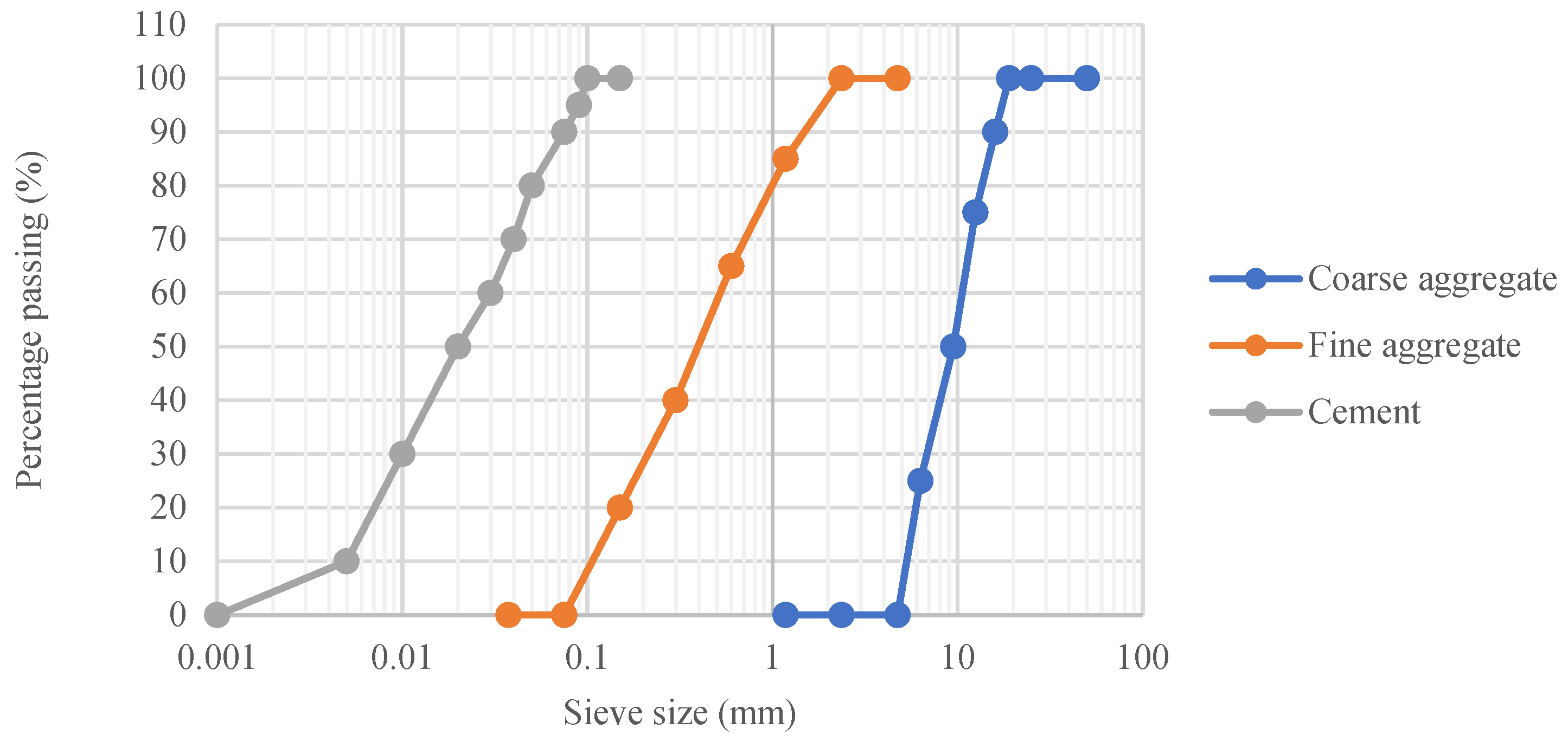
2.1. Materials

Commercially available ASTM C150 (Type I) Portland cement was employed, while the natural sand (or, fine aggregate) and limestone coarse aggregate complied with ASTM C33. The sand had a specific gravity of 2.65 and water absorption of 0.9%, while the coarse aggregate with 5–20 mm size had a specific gravity of 2.69, fineness modulus of 6.3, and water absorption of 1.1%. A water-reducing plasticizer was utilized in all mixtures to secure the targeted workability; its solid content, pH, and specific gravity are 30%, 8.5, and 1.13, respectively. Figure 1 shows the gradation curves for cement, fine aggregates, and coarse aggregates.
The lightweight aggregates were produced in a laboratory 50 L mixer using bottom ash by-products derived from a coal combustion power plant (Figure 2). The bottom ash was initially sieved on 16 mm diameter opening, oven-dried to remove moisture, and then mixed with the cement and water at a ratio of 3.5:1:0.8 to produce the lightweight aggregate. A plasticizer was added during mixing to avoid the deterioration of the aggregate strength due to the excessive need for water. The aggregates were cured for 28 days on plastic sheets and were regularly sprayed with water (Figure 2). Their specific gravity and water absorption, determined as per ASTM C127, were found to be 1.63 and 17.5%, respectively. The bulk density was also conducted, yielding an average of 962 kg/m3.
Two types of deformed steel reinforcement with 6 and 8 mm diameters were used. The steel complied with ASTM A615 [47]; its yield strength and ultimate strength were found to vary between 500 ± 25 MPa and 620 ± 25 MPa, respectively.

2.2. Concrete Mix Proportions

Two NWC and LWC mixtures commonly used for residential applications are considered in this work; their characteristic compressive strengths are 30 ± 2.5 and 20 ± 2.5 MPa, respectively. As shown in Table 1, the cement content increased from 320 to 420 kg/m3, while the resulting water-to-cement ratio (w/c) decreased from 0.58 to 0.4. The sand and coarse aggregate contents were 634 and 1268 kg/m3 for the NWC, while these were 540 and 712 kg/m3 for LWC, following ACI E-701 [48] recommendations. The density of hardened NWC and LWC mixtures was 2420 and 1930 kg/m3, respectively.
For mixing, the sand and coarse aggregates were homogenized together with half of mixing water. The cement was then introduced with the remaining mixing water, followed by the plasticizer that was adjusted to achieve a slump of 150 ± 25 mm. The plasticizer dosage increased from 3.17 to 4.4 kg/m3 for NWC and LWC mixtures, mostly due to the reduced w/c that requires additional molecules to properly lubricate the cement paste. The batching process consisted of 2 min mixing, followed by a 30 s resting period, then resuming for two additional minutes.

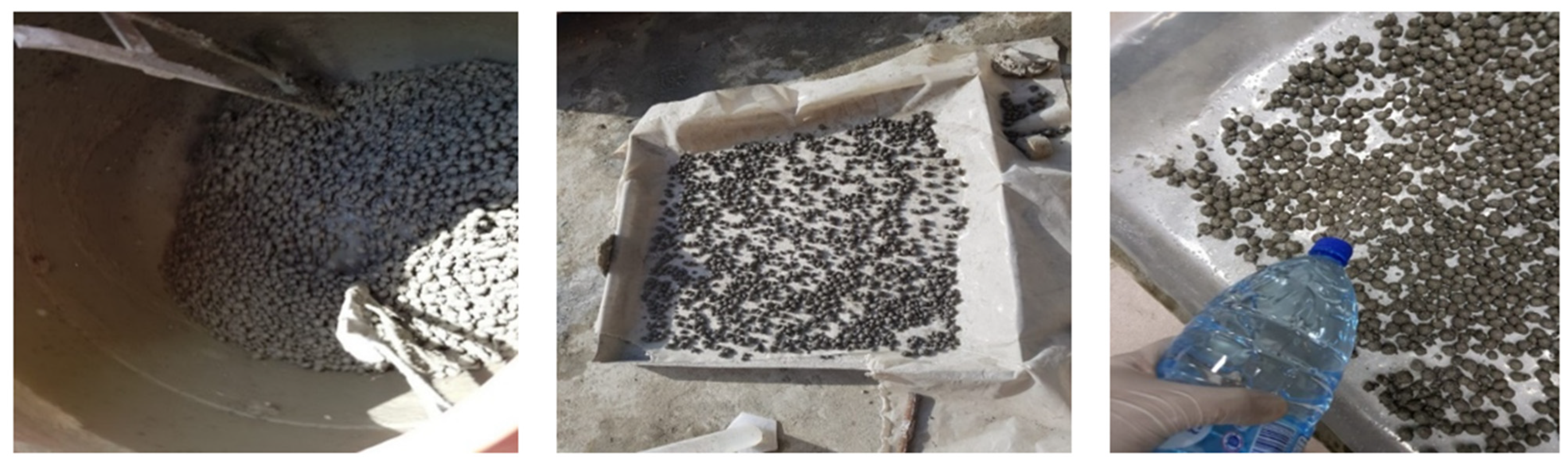
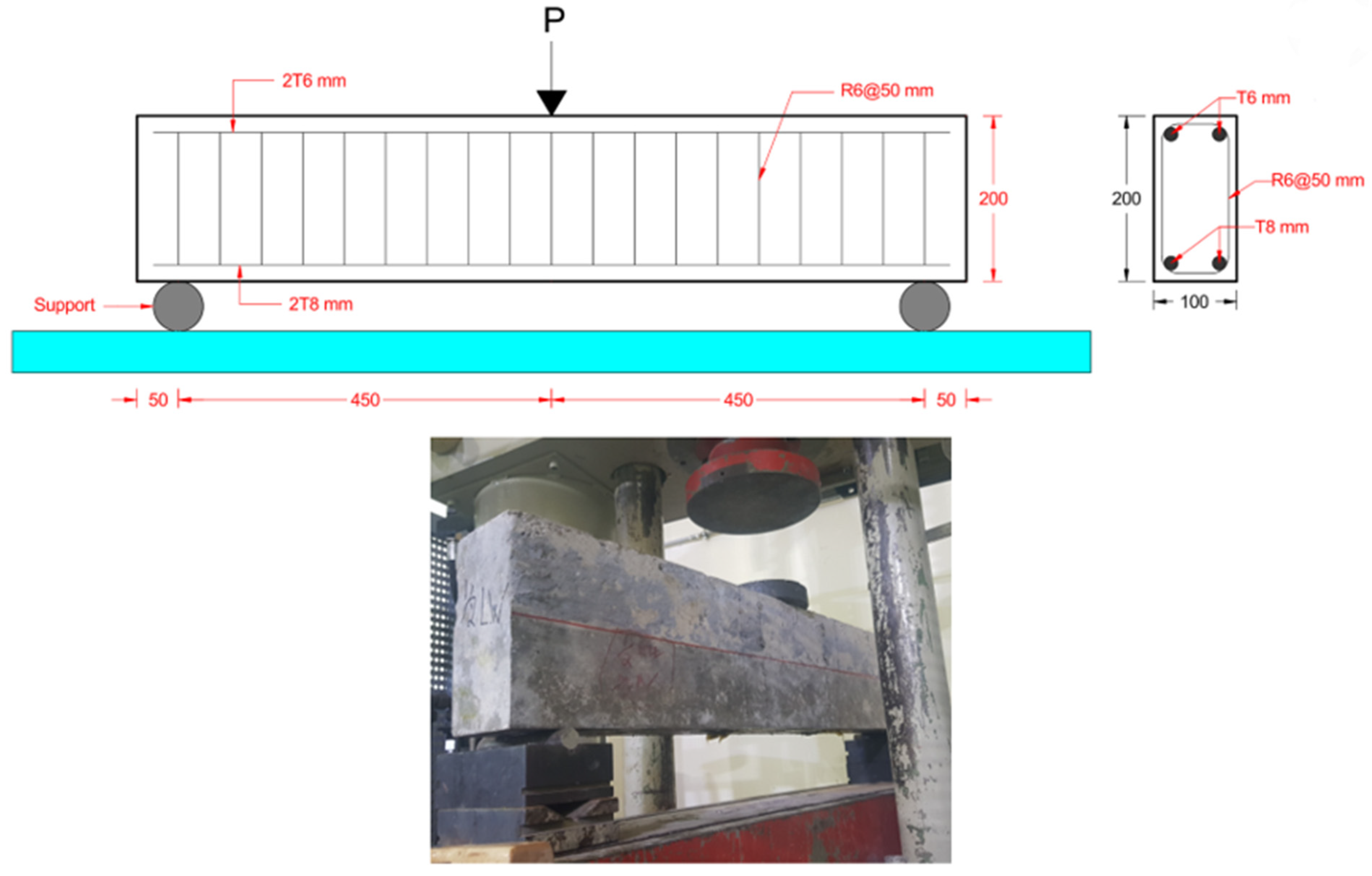
2.3. Preparation of Specimen and Testing Methods

Following concrete batching, the slump and air content were determined as per ASTM C143 and C231, respectively [49,50], and were found to vary between 150 ± 25 mm and 2.8% ± 0.4%, respectively. The freshly mixed concrete was then cast in 100 × 200 and 150 × 300 mm steel cylinders, which were demolded after 24 h and immersed in lime-saturated water at 22 ± 3 °C for testing ages of 7 and 28 days. The hardened density, compressive strength (f’c), splitting tensile strength (ft), and modulus of elasticity (E) were determined as per ASTM C642, C39, C496, and C469, respectively [51,52,53,54], with the linear variable differential transducers (LVDT) used to determine the ultimate compressive strain at failure, as well as the Poisson ratio. Averages of 3 to 5 responses were considered; the resulting coefficients of variation (COVs) for the f’c, ft, and E for NWC were 8.6%, 9.7%, and 9.55%, respectively. For LWC, the corresponding COV values were 11%, 11.5%, and 11.8%. Further details are provided in Table 1.
Figure 3 shows the set-up used for assessing the flexural strength of RC beams, which measured 1000 mm in length and 100 × 200 mm in cross-section. Two 8 mm diameter longitudinal steel bars are used in the tension zone, leading to an under-reinforced design having a steel ratio of 0.57% (i.e., the cover is taken as 25 mm and the effective depth equals 175 mm). Two longitudinal 6 mm bars are added in the compression zone of the beams, while a total of 19 stirrups having 6 mm diameter are used, as shown in Figure 3. Duplicate specimens were considered during testing.
As already noted, the RC beams consisted of either NWC, LWC, or a two-layered combination of both materials. Hence, as shown in Figure 4, six different scenarios are considered wherein the first beam (designated as B1) was fully composed of NWC, while B2, B3, B4, and B5 comprised gradually increased LWC depths of 50, 100, 150, and 154 mm from the tension side of the beams. The 154 mm depth in B5 corresponds to the neutral axis computed using the internal force equilibrium formulas specified in RC design [55]. Lastly, beam B6 was cast using LWC, thus offering the full spectrum of scenarios necessary to evaluate the flexural strength with varying composite materials and distribution patterns. The NWC layer was cast first, followed immediately by the LWC layer, while the NWC remained in its plastic state to ensure a monolithic bond. During the casting process, vibratory compaction was applied to both layers using a 100-Hz laboratory poker vibrator. Care was taken to avoid disturbing the NWC layer during the compaction of the LWC layer, ensuring proper interfacial bonding and continuous structural behavior. The beams were demolded after 24 h and covered with wet burlap until the testing age of 28 days.
The concrete beams were supported on rigid steel plates and subjected to one-point flexure loading at the center (Figure 3). The load was applied at constant rate of approximately 5 kN/min, and recording continued until the load dropped by about 75% of the ultimate value. Two transducer sensors (i.e., LVDTs) were installed at the bottom surface to measure the mid-span deflection during load application. Four pairs of Demec points were affixed to the side surface of the beam to measure the concrete strain at various height levels. This arrangement is intended to provide insights into the strain distribution across the cross-section at different stages of load application.

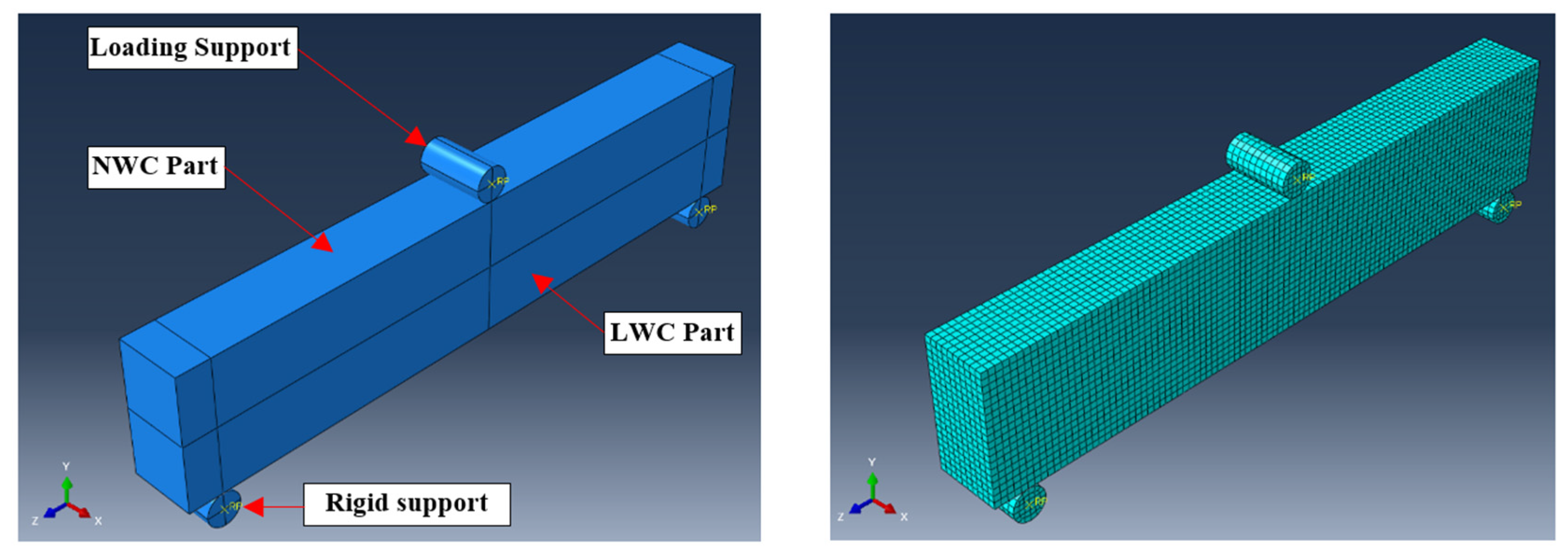
2.4. Numerical Modeling

The finite element modeling (FEM) in this study was conducted using ABAQUS software [1,56,57]. The RC beam was modeled using the C3D8R element type, an 8-node linear brick element with reduced integration and hourglass control. While C3D8R is not traditionally preferred for capturing all nonlinear behaviors in reinforced concrete, it has been successfully used in many studies due to its ability to effectively reduce computational costs without significantly compromising accuracy. The reduced integration helps limit the volumetric locking, and the hourglass control mitigates numerical issues associated with under-integrated elements, as demonstrated by You et al. [58] and Ullah et al. [56]. The steel reinforcements within the RC beam were modeled using T3D2 elements, which are 2-node linear 3D truss elements ideal for representing the tensile properties of steel rebars. The rigid supports were modeled using R3D4 elements, which are 4-node 3D bilinear rigid quadrilateral elements commonly used to represent the boundary conditions imposed on any concrete structure.
A general static step was defined to replicate the static loading conditions during simulation. The normal behavior was assigned as hard contact to prevent penetration between surfaces, while the tangential behavior was modeled using the penalty method with a coefficient of friction of 0.7. The reinforcement bars were assumed to be fully embedded within the concrete host, ensuring a perfect bond. The boundary conditions were defined as pinned, indicating that the supports are constrained to displace in the x, y, and z directions, just like what happens in real-world applications. The mesh size was chosen to be 10 mm based on a mesh sensitivity analysis, ensuring a balance between computational efficiency and result accuracy. A structured mesh was used for the concrete elements, reinforcement, and rigid supports. Figure 5 illustrates the 3D finite element model of the RC beam.
The steel reinforcement was modeled as an elastoplastic material, with the properties summarized in Table 2. Its elastic modulus, yield strength, and yield strain are found equal to 200 GPa, 500 MPa, and 2.5 mm/m, respectively. Regarding the concrete mixtures, these were modeled using the concrete damage plasticity (CDP) approach. Earlier studies showed that this approach is accurate in mimicking the behavior of RC beams under static load conditions and capable of representing the nonlinear behavior, including both the plastic deformation and damage at failure [59,60]. The concrete parameters are summarized in Table 3; as shown, the NWC density is found to be 2416 kg/m3 and considerably drops to 1928 kg/m3 in the case of LWC due to the use of bottom ash lightweight aggregate. The corresponding f’c varies from 30.5 to 21.5 MPa, while E varies from 30.75 to 18.06 GPa, respectively.

3. Results and Discussion

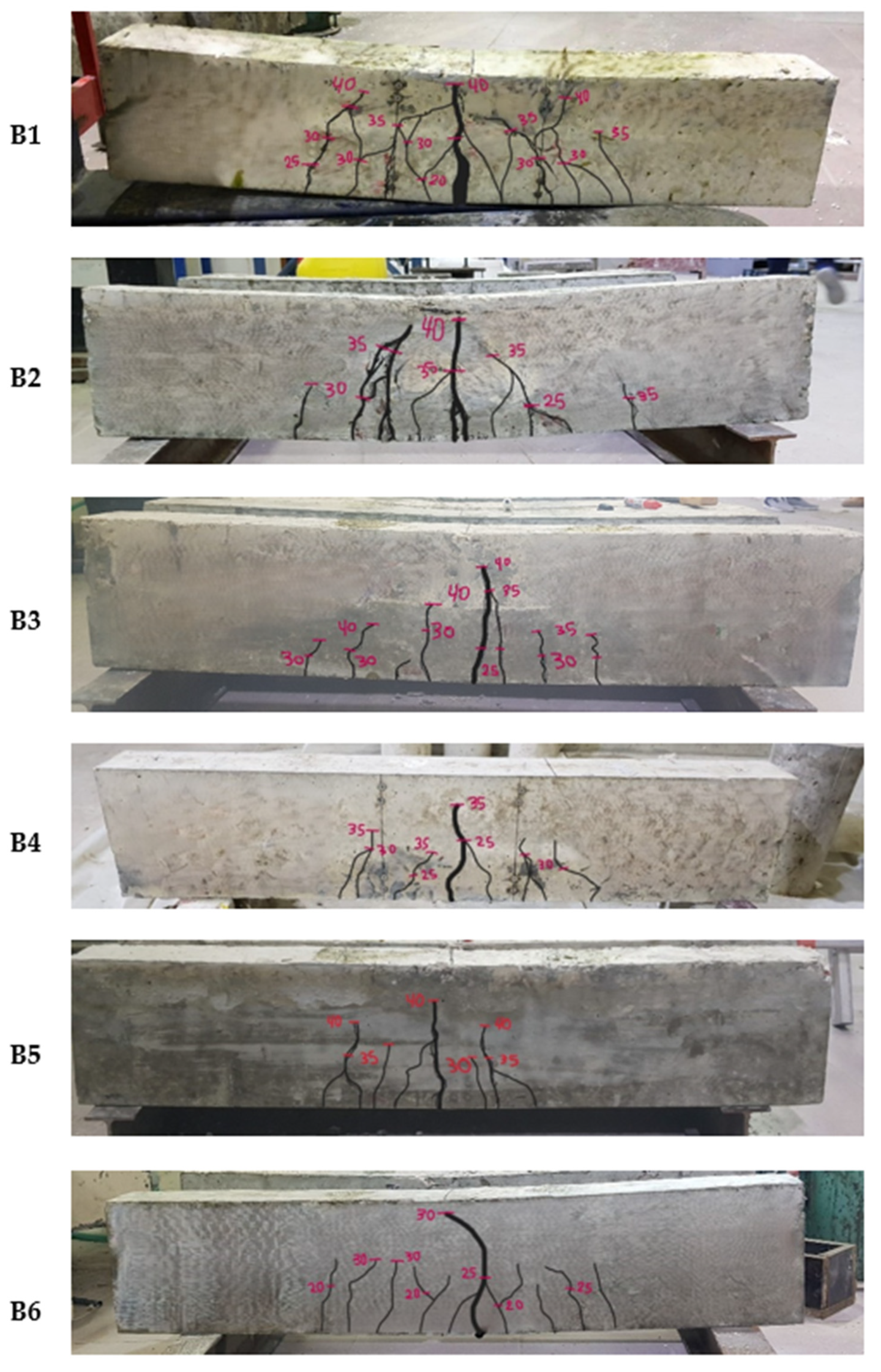
3.1. Failure Patterns

Figure 6 illustrates the damage patterns of various tested RC beams. Regardless of the concrete type (NWC or LWC), all beams failed in flexure, with the cracks starting from the mid-span and propagating vertically upwards as the load increased. Initially, the flexural cracks formed at the tension side within the region of the highest bending moment. As the load continued to increase, the cracks became wider in size and more numerous, reflecting the yielding of the steel reinforcement until the beam’s complete failure.
As shown, the B1 beam composed fully from NWC exhibited a high number of flexural cracks at failure; the crack width ranged from just a few mm up to 15 mm. This intense cracking pattern is indicative of increased energy and strain dissipations, reflecting the beam’s ability to undergo significant deformation and ductility before failure [61]. In contrast, the beams B2 to B5, containing increased LWC heights, demonstrated less crack intensity, with the crack widths ranging from less than 1 mm to a maximum of 10 mm. The reduction in crack intensity and size suggests that the LWC incorporated within the tension zone reduces the RC beam susceptibility to the initiation and propagation of cracks. As will be discussed later, this resulted in a balance between strength and ductility, along with a notable decrease in the overall crack width and intensity compared to the NWC beam. To the extreme end, beam B6, made entirely from LWC, exhibited significant damage due to the lower concrete strength, showing the highest crack width near the mid-span, reaching up to 30 mm (Figure 6). The extensive cracking and larger crack widths in beam B6 reflect that the beam’s flexural capacity is significantly compromised by the weaker concrete strength. The high damage and large crack width reflect the limited ability of LWC to resist flexural stresses compared to NWC within RC beams tested under flexural loading.

3.2. Load vs. Mid-Span Deflection Curves

Figure 7 plots the load vs. mid-span deflection curves for the various tested RC beams, while Table 4 summarizes the critical performance indicators, including the ultimate load at failure (Pmax), deflection at which the flexural steel commences to yield (δy), and deflection at beam collapse (δf), along with a ductility ratio (δfy) that reflects the relative energy dissipated up to failure. The deflections at service loads corresponding to 33% and 67% Pmax were also added. The mass of tested RC beams along with their ratios compared to the control beam prepared with only NWC are given in Table 4, which can be useful to quantify the reduction in concrete weight and its effect on the structural performance.
Regardless of the concrete type, all RC beams exhibited similar load vs. deflection curves characterized by an almost linear increase in the pre-ultimate stage, followed by a horizontal plateau that represents the yielding of tensile steel. The beams prepared with NWC and those containing a combination of NWC/LWC exhibited almost similar ultimate loads of about 42 ± 0.5 kN, while this dropped to about 33 kN for the beam made using only LWC. Given that the RC beams are under-reinforced (i.e., 0.57% of tensile steel), this indicates that the type of concrete in the tension zone has a negligible effect on the beam’s ultimate strength [62]. In other words, the flexural strength of RC beams does not deteriorate when the LWC is added to the tension zone since the behavior is mainly governed by the yielding of tensile steel. This can be particularly beneficial to reduce the beam weight without affecting the structural performance.
Except for beam B6 prepared with only LWC, the stiffness of load vs. deflection curves were fairly similar in the pre-ultimate stage, again reflecting the importance of concrete compressive strength to maintain increased internal couple within the RC beam. The decreased stiffness of beam B6 can be mainly attributed to the relatively reduced LWC density and strength, which causes higher deflection under a given load. The lower density and strength reduce the material’s ability to resist deformation and internal stress distribution, thus directly impacting the overall stiffness. Consequently, beam B6 exhibited a 20.1% reduction in mass compared to the control beam.
Although the ultimate flexural strength remained unaffected by the concrete type, it is clear that such concrete combinations have detrimental effects on the deflection at failure and ductility in the post-ultimate region of the load vs. deflection curves. Hence, as shown in Figure 8, the deflection at failure and ductility ratio gradually decreased when the NWC was replaced by LWC. For example, the deflection at failure dropped from 17.6 mm for the control beam prepared with NWC to 12.1 mm for beam B4; the corresponding ductility decreased from 8.38 to 5.76, respectively. Beam B5, whereby the LWC is added up to the neutral axis, exhibited a ductility ratio of 4.52, and a reduction of mass by 15.5%, reflecting that the LWC added up to the neutral axis reduces the beam weight while maintaining an efficient load capacity. Beam B6, prepared with only LWC, exhibited the shortest deflection at a failure of 9.1 mm and a ductility ratio of 3.03.
Although beam B6, constructed entirely of LWC, exhibited a reduced ductility ratio of 3.03 compared to beams containing NWC, it demonstrated adequate deformation capacity under service loads. However, the lower ductility ratio signals a potential limitation in performance under overload or extreme loading conditions. This behavior underscores the trade-off between weight reduction and energy dissipation capacity in LWC beams. To address these concerns, supplementary strategies such as fiber reinforcement, hybrid configurations, or optimized mix designs could be explored to enhance the post-peak behavior and robustness of LWC beams under extreme scenarios.

3.3. Concrete Strains

Figure 9 illustrates the distribution of concrete strains at 10, 20, and 30 kN load intervals measured using Demec points placed at various heights along the beam’s side faces. The neutral axis was determined by connecting the strain values recorded at the four Demec point levels. The point where the strain diagram intersects the Y-axis (representing the beam depth) indicates the position of zero strain, which corresponds to the neutral axis location [62]. Clearly, beams B1 to B5 exhibited similar strain patterns, which correspond to negative values at 20 mm from their top (i.e., compression zone) and gradually shift into positive values towards the bottom (i.e., tension zone). The similarity in strain measurements underscores the uniformity of their structural behavior under the various levels of applied loads. As summarized in Figure 9, the neutral axis of B1 to B5 ranged from 50 to 55 mm.
In contrast, beam B6, constructed entirely from lightweight concrete (LWC), exhibited significantly different behavior due to its material properties. The strains in both the compression and tension zones were markedly higher compared to beams containing normal-weight concrete (NWC). For instance, at a load of 30 kN, the strain recorded at 20 mm from the bottom side of beam B6 was 0.0024 mm/mm, compared to an average value of 0.0017 mm/mm for beams B1 to B5. This behavior can be attributed to the considerably lower stiffness and modulus of elasticity of LWC, which led to a greater redistribution of internal stresses and higher deflection under load. The reduced capacity of LWC to sustain compressive stresses also caused the neutral axis to shift downward to 40 mm, further highlighting the material’s limitations in maintaining structural equilibrium and stiffness compared to beams incorporating NWC.

3.4. Comparison to ACI 318 Building Code

The nominal moment (Mn) and maximum load (PACI)of RC beams predicted by ACI 318-19 [55] Code provisions can be expressed as follows:
M n = A s f y ( d a / 2 )
P A C I = 4 M n L
where (As), (a), and (L) refer to the cross-sectional area of flexural steel reinforcement (100 mm2), the depth of equivalent rectangular stress block, and the beam’s span, respectively. The resulting ratio determined from the experimental-to-design loads (PEXP/PACI) varied between 1.30 and 1.32, reflecting the conservative nature of the ACI code provisions. The PEXP/PACI value determined from the LWC beam (B6) was 1.08, given the significantly reduced ultimate load at failure (Table 5). A similar study conducted by Al-Farttoosi et al. [63] recommended introducing an additional safety factor to equations that predict the flexural strength of LWC beams. The discrepancies observed in this study between the experimental and code-predicted capacities further underscore the need for such modifications. The reduced stiffness and ductility of LWC beams, particularly the shift in the neutral axis and lower energy dissipation capacity, indicate that current flexural capacity equations in the ACI 318 code may not fully capture the material’s unique behavior. Incorporating adjustments for the lower modulus of elasticity and tailored safety factors specifically for LWC beams would improve the predictive accuracy of the code and enhance the reliability of these structural elements under extreme or overload conditions.

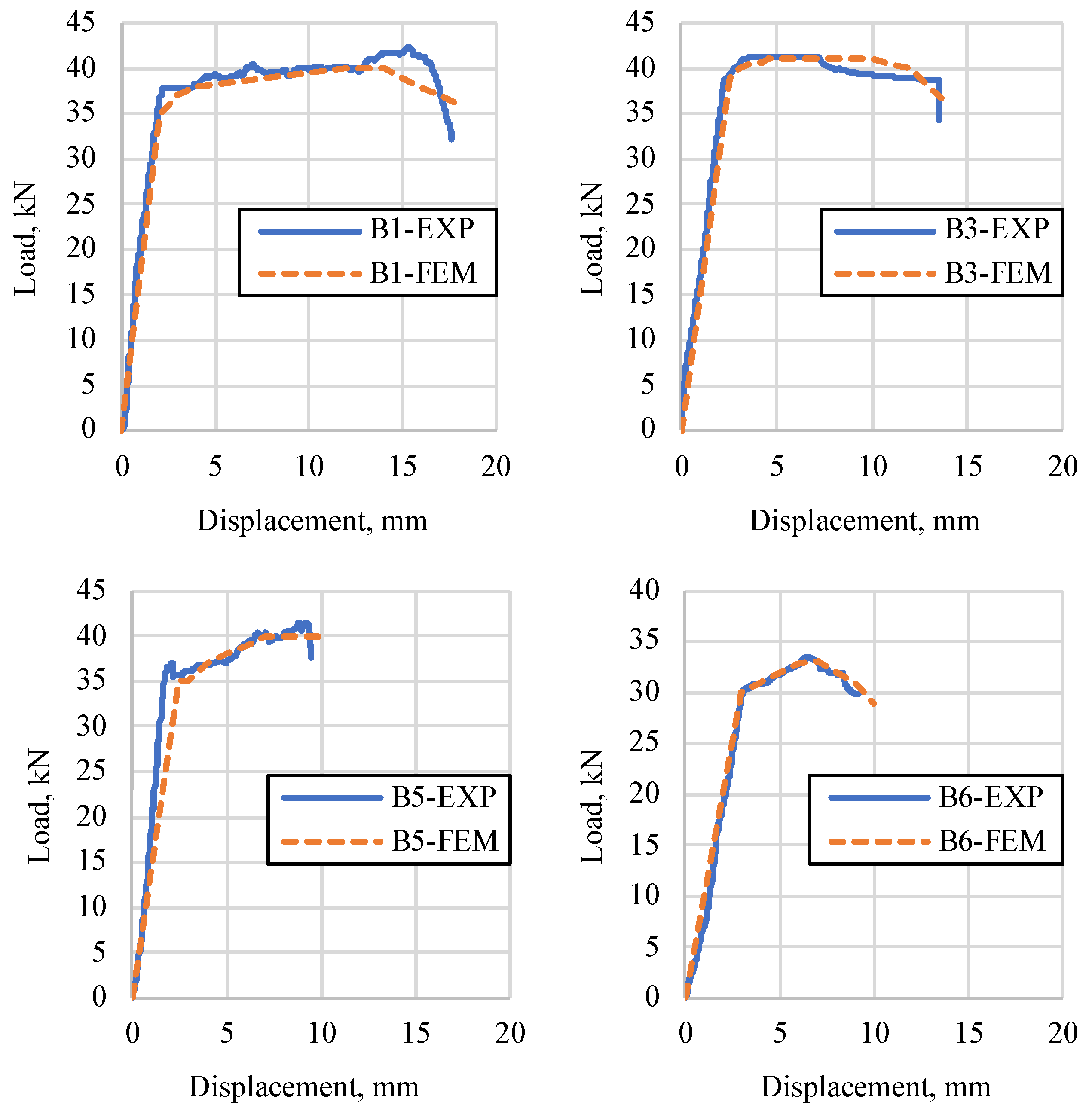
3.5. Numerical Modeling Results

As noted earlier, the FEM analysis is carried out to provide additional insights and complement the understanding of the beam’s structural behavior determined from experimental testing. As shown in Figure 10 and summarized in Table 6, the FEM predictions match the experimental results fairly well; for example, the comparison of Pmax values revealed a marginal error that ranged from 0.6% to 5.49%. Similarly, the errors in deflection at yield and failure were between 0.94% and 16% and 2.76% and 9%, respectively. This close agreement recorded between FEM and experimental testing reflects the feasibility of replacing part of the NWC by LWC, especially in the tension beam zone, without altering the principles and basics of RC beams, including the prediction of their load-bearing capacity until failure.
Figure 11 plots typical damage field distribution areas determined at different loading levels for beams B1, B3, B5, and B6. Physically, the damaged areas can represent the crack formation and propagation, allowing a better prediction of the crack distribution during the different loading stages [64,65]. The scale varies from 0 to 1, whereby a value of 0 refers to undamaged concrete (i.e., blue areas), while increased values progressively indicate the crack positioning and damage level (i.e., green, yellow, then red). At a load of 20 kN, beam B1, composed entirely of NWC, exhibited a maximum damage index of 0.65, which is significantly higher than the 0.33 observed in B3 and B5. As the load increased to 30 kN, the damage progressed gradually towards the neutral axis, and the maximum damage in B1 reached 0.78, while B3 and B5 displayed lower values of 0.72 and 0.7, respectively. At failure, the maximum damage reached 0.95 in B1 compared to 0.92 and 0.90 in B3 and B5, respectively. These results are in complete agreement with the experimental testing, highlighting the superior energy dissipation and ductility of NWC, as compared to members containing increasing heights of LWC. In contrast, beam B6, comprising LWC, exhibited significant damage due to lower concrete strength, with a maximum damage index of 0.79 at 20 kN, increasing to 0.95 at failure.
Table 7 shows the area of severe damage zones in beams B1 to B6, resulting from both the experimental work and FEM. It can be seen from the FEM that the area of severe damage zones decreased from 1004 cm2 for B1 to 396 cm2 for B5, which indicates again the better energy dissipation for beams with NWC compared to the beams that had LWC in the tensile zone. The FEM results were similar to the experimental ones in terms of the behavior, with an error ranging from 4.85% for B4 to 26.11% for B5. This can be justified by the unsymmetrical conditions in reality, in terms of both loading, supporting, and execution in the experiments, which is not the case for FEM, where perfect symmetrical conditions are assumed in terms of loading, supporting, and execution. The average error for all specimens is less than 12.6%, which is considered acceptable. It is worth noting that a strong correlation with an R2 of 0.99 exists between the ductility ratios determined by experimental testing and those by FEM.
Earlier studies showed that the use of LWC effectively reduces the construction weight without compromising the load-bearing capacity. For example, Chen et al. [66] demonstrated that the LWC beam weight could be reduced by up to 23%, compared to a 20% reduction observed in the current study. Another study reported an 8.4% weight reduction for LWC beams [67]. However, both studies showed a decrease in the member stiffness, which negatively impacted the ductility—an issue that can be addressed by incorporating steel fibers into the concrete, as suggested by Altun and Aktaş [68]. This approach not only enhances the beams’ toughness and ductility but also contributes to reduced construction weight. A study by Vives et al. [69] found that LWC mixtures with 1800 to 2000 kg/m3 density could reduce CO2 emissions compared to conventional concrete. Mergos [70] highlighted that optimized seismic designs using LWC in reinforced structures can reduce CO2 emissions by up to 60%.

4. Conclusions

This study explores the potential benefits of using LWC in the tension zone of RC beams to reduce the overall construction weight while maintaining structural integrity. The data reported herein provide valuable insights for structural engineers aiming to optimize designs by reducing material consumption without compromising performance. The key findings can be summarized as follows:
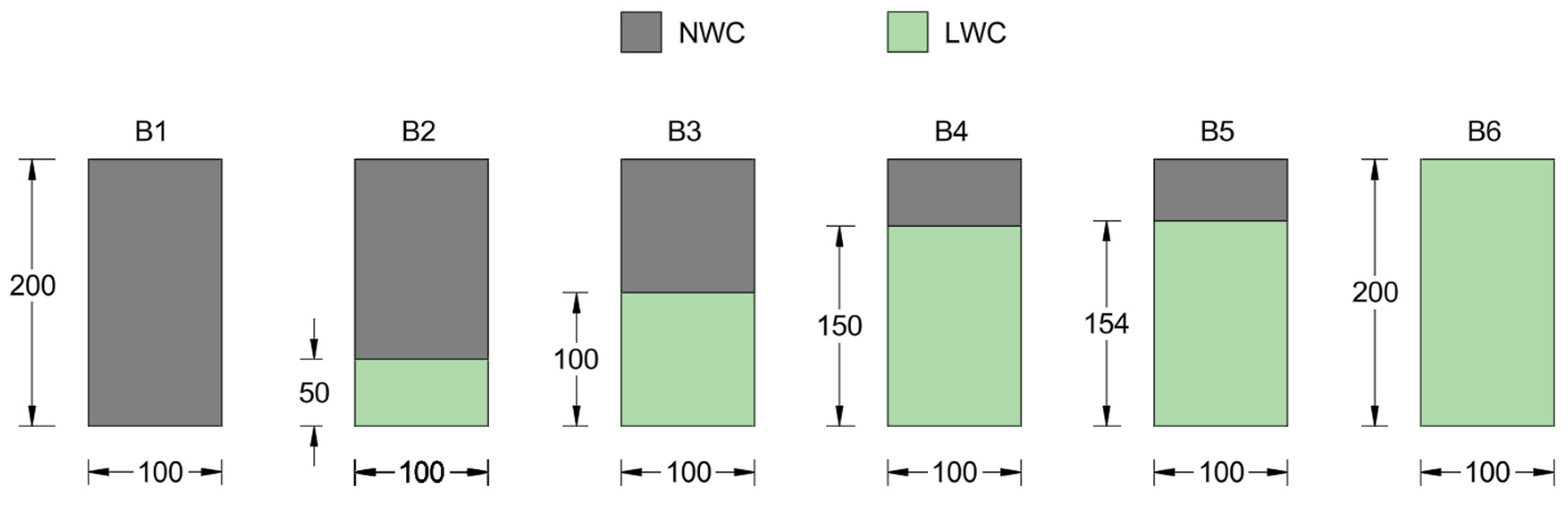
  • The incorporation of LWC in the tension zones of RC beams significantly reduced crack intensity and size compared to fully cast NWC beams. The crack widths in LWC beams (B2 to B5) ranged from less than 1 to 10 mm, compared to a maximum of 15 mm in fully cast NWC beams. Beams made entirely of LWC (B6) exhibited extensive cracking with widths reaching up to 30 mm.
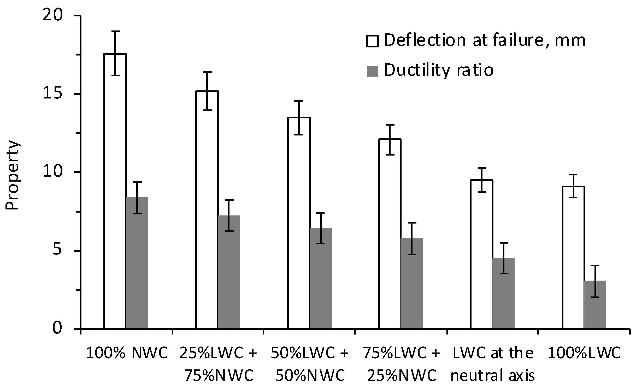
  • The incorporation of LWC in the tension zone did not significantly alter the ultimate flexural strength compared to fully cast NWC beams. However, LWC reduced the deflection at failure from 17.6 mm in the NWC beam to 12.1 mm in beam B4 and 9.1 mm in the fully cast LWC beam (B6). This reduction in deflection is accompanied by a notable drop in the ductility ratio, from 8.38 in the NWC beam to 3.03 in the fully LWC beam. While these beams satisfy serviceability requirements, the reduced ductility ratio raises concerns about their performance under overload or extreme loading conditions. Future studies should explore strategies such as incorporating fiber reinforcement or optimizing the mix design to enhance the post-peak behavior and energy dissipation capacity of LWC beams, ensuring their robustness in such scenarios.
  • Beams B1 to B5 exhibited similar strain patterns, with neutral axis positions ranging from 50 to 55 mm. The fully cast LWC beam (B6) showed higher strains, with a recorded value of 0.0024 mm/mm at 30 kN compared to an average of 0.0017 mm/mm for the other beams. The neutral axis in B6 dropped to 40 mm, indicating a significant shift in the structural behavior due to the lower modulus of elasticity.
  • The experimental-to-design load ratio (PEXP/PACI) for LWC beams was lower compared to NWC beams. This suggests that the ACI 318-19 code does not fully account for the lower strength of LWC, and there is a need for an additional safety factor when predicting the flexural strength of LWC beams.
  • The FEM analysis aligns with the experimental results, showing a marginal error in predicting the load-bearing capacity, deflection, and damage patterns. A strong correlation with R2 of 0.99 was established between the ductility ratios determined experimentally or by FEM analysis.
Future research should focus on exploring the long-term durability of LWC in structural elements, particularly in terms of resistance to freeze–thaw cycles, carbonation, and chloride penetration. Investigating its application in other structural elements, such as slabs, walls, and columns, could provide valuable insights into the broader usability of LWC. Additionally, studies examining cost benefits, including material costs, labor, and potential savings in overall construction weight, would enhance the economic feasibility of partially replacing NWC with LWC in the tension zone. Testing under dynamic or cyclic loading conditions, such as those simulating real-world scenarios like earthquakes or heavy traffic, would offer critical insights into the performance of LWC beams and other structural elements. Finally, research on the combined effect of shear and flexural performance, particularly in beams without stirrups, and expanding to full-scale structural elements with hybrid NWC–LWC configurations, could lead to more optimized and resilient designs for practical construction applications.

Author Contributions

Conceptualization, O.B. and J.K.; methodology, A.J. and J.J.A.; software, A.J.; validation, A.J. and L.D.; formal analysis, A.J. and J.J.A.; investigation, A.J. and L.D.; resources, J.K. and O.B.; writing—original draft preparation, L.D. and A.J.; writing—review and editing, J.J.A. and A.J.; supervision, J.K. All authors have read and agreed to the published version of the manuscript.

Funding

This research received no external funding.

Data Availability Statement

The original contributions presented in the study are included in the article, further inquiries can be directed to the corresponding author.

Conflicts of Interest

The authors declare no conflicts of interest.

References

  1. Jahami, A.; Khatib, J.; Bawab, J. An Experimental and Numerical Evaluation of the Structural Performance of Concrete Beams Containing Bamboo Shear Reinforcement. Steps Civ. Constr. Environ. Eng. 2023, 1, 1–9. [Google Scholar] [CrossRef] [PubMed]
  2. Awad, Z. Sustainable Restoration Techniques for Historic Buildings in Tyre City. Steps Civ. Constr. Environ. Eng. 2023, 1, 10–17. [Google Scholar] [CrossRef]
  3. Zeaiter, H.; Jahami, A.; Khatib, J. Bio-Concrete and Beyond: Advancements in Self-Healing Techniques for Durable Infrastructure. Steps Civ. Constr. Environ. Eng. 2023, 1, 18–29. [Google Scholar] [CrossRef]
  4. Abou Rachied, T.; Dbouk, F.; Hamad, B.; Assaad, J.J. Structural behavior of beams cast using normal and high strength concrete containing blends of ceramic waste powder and blast furnace slag. Clean. Mater. 2023, 7, 100179. [Google Scholar] [CrossRef]
  5. Amran, M.; Murali, G.; Khalid, N.H.A.; Fediuk, R.; Ozbakkaloglu, T.; Lee, Y.H.; Haruna, S.; Lee, Y.Y. Slag Uses in Making an Ecofriendly and Sustainable Concrete: A Review. Constr. Build. Mater. 2021, 272, 121942. [Google Scholar] [CrossRef]
  6. Dervishaj, A.; Gudmundsson, K. From LCA to Circular Design: A Comparative Study of Digital Tools for the Built Environment. Resour. Conserv. Recycl. 2024, 200, 107291. [Google Scholar] [CrossRef]
  7. United Nations. Shifting to a Circular Economy Essential to Achieving Paris Agreement Goals. Available online: https://unfccc.int/news/shifting-to-a-circular-economy-essential-to-achieving-paris-agreement-goals (accessed on 24 November 2024).
  8. Alharthai, M.; Ozkilic, Y.O.; Karalar, M.; Mydin, M.A.O.; Ozdoner, N.; Celik, A.I. Performance of Aerated Lightweighted Concrete Using Aluminum Lathe and Pumice under Elevated Temperature. Steel Compos. Struct. 2024, 51, 271. [Google Scholar] [CrossRef]
  9. Korkut, F.; Karalar, M. Investigational and Numerical Examination on Bending Response of Reinforced Rubberized Concrete Beams Including Plastic Waste. Materials 2023, 16, 5538. [Google Scholar] [CrossRef]
  10. Karalar, M. Experimental and Numerical Investigation on Flexural and Crack Failure of Reinforced Concrete Beams with Bottom Ash and Fly Ash. Iran. J. Sci. Technol. Trans. Civ. Eng. 2020, 44, 331–354. [Google Scholar] [CrossRef]
  11. Sepe, R.; Bollino, F.; Boccarusso, L.; Caputo, F. Influence of Chemical Treatments on Mechanical Properties of Hemp Fiber Reinforced Composites. Compos. Part B Eng. 2018, 133, 210–217. [Google Scholar] [CrossRef]
  12. Dahal, R.K.; Acharya, B.; Dutta, A. Mechanical, Thermal, and Acoustic Properties of Hemp and Biocomposite Materials: A Review. J. Compos. Sci. 2022, 6, 373. [Google Scholar] [CrossRef]
  13. Tran Le, A.D.; Maalouf, C.; Mai, T.H.; Wurtz, E.; Collet, F. Transient Hygrothermal Behaviour of a Hemp Concrete Building Envelope. Energy Build. 2010, 42, 1797–1806. [Google Scholar] [CrossRef]
  14. Junaid, M.F.; Rehman, Z.; Kuruc, M.; Medveď, I.; Bačinskas, D.; Čurpek, J.; Čekon, M.; Ijaz, N.; Ansari, W.S. Lightweight Concrete from a Perspective of Sustainable Reuse of Waste Byproducts. Constr. Build. Mater. 2022, 319, 126061. [Google Scholar] [CrossRef]
  15. Martins, R.; Carmo, R.N.F.; Costa, H.; Júlio, E.; Cordeiro, T.; Almeida, V. Interface Role in Composite RC Beams with a Light-Weight Concrete Core and an Ultra High-Durability Concrete Skin. Eng. Struct. 2021, 228, 111524. [Google Scholar] [CrossRef]
  16. Assaad, J.J.; El Mir, A. Durability of Polymer-Modified Lightweight Flowable Concrete Made using Expanded Polystyrene. Constr. Build. Mater. 2020, 249, 118764. [Google Scholar] [CrossRef]
  17. Wang, Z.; Li, X.; Jiang, L.; Wang, M.; Xu, Q.; Harries, K. Long-Term Performance of Lightweight Aggregate Reinforced Concrete Beams. Constr. Build. Mater. 2020, 264, 120231. [Google Scholar] [CrossRef]
  18. Assaad, J.J.; Gerges, N.; Issa, C. Bond to Reinforcement of Polymeric Lightweight Flowable Concrete for Structural Applications. J. Adhes. Sci. Technol. 2019, 33, 595–615. [Google Scholar] [CrossRef]
  19. Li, H.; Wei, Y.; Hu, Y.; Zhao, L.; Wang, G.; Zhang, Y. Experimental and Theoretical Analysis of FRP-Confined Square Lightweight Aggregate Concrete Columns under Axial Compression. Case Stud. Constr. Mater. 2024, 20, e02982. [Google Scholar] [CrossRef]
  20. Luo, S.; Bai, T.; Guo, M.; Wei, Y.; Ma, W. Impact of Freeze–Thaw Cycles on the Long-Term Performance of Concrete Pavement and Related Improvement Measures: A Review. Materials 2022, 15, 4568. [Google Scholar] [CrossRef]
  21. Das, P.; Chakraborty, S.; Barai, S.V. Flexural Behaviour of Fly Ash Incorporated Ferrochrome Slag Aggregate Reinforced Concrete Beam. J. Build. Eng. 2023, 76, 107317. [Google Scholar] [CrossRef]
  22. Kistan, A.; Kanchana, V.; Parthiban, E.; Vadivel, S.; Sridhar, B. Study on Flexural Behaviour of Polypropylene Fiber Reinforced Fly Ash Concrete Beam. Mater. Today Proc. 2023; in press. [Google Scholar] [CrossRef]
  23. Khalid, M.A.; Shariq, M.; Arif, M.; Umar, A. Shear Behavior of Fiber Reinforced Concrete Beams with High Fly Ash Content. Mater. Today Proc. 2023; in press. [Google Scholar] [CrossRef]
  24. Hadi, B.A.; Saleh, S.M. Behavior of Steel–Lightweight Self Compacting Concrete Composite Beams with Various Degrees of Shear Interaction. Civ. Eng. J. 2023, 9, 2689–2705. [Google Scholar] [CrossRef]
  25. Dragaš, J.; Marinković, S.; Ignjatović, I.; Tošić, N.; Koković, V. Flexural Behaviour and Ultimate Bending Capacity of High-Volume Fly Ash Reinforced Concrete Beams. Eng. Struct. 2023, 277, 115446. [Google Scholar] [CrossRef]
  26. Liao, Q.; Zhao, X.-D.; Wu, W.-W.; Lu, J.-X.; Yu, K.-Q.; Poon, C.S. A Review on the Mechanical Performance and Durability of Fiber Reinforced Lightweight Cement Composites: The Roles of Fiber and Lightweight Aggregate. J. Build. Eng. 2024, 88, 109121. [Google Scholar] [CrossRef]
  27. Wibowo, A.P.; Saidani, M. The Effect of Fly Ash as Coating Powder on Compressive Strength of Lightweight Concrete. Mater. Today Proc. 2023, 85, 29–32. [Google Scholar] [CrossRef]
  28. Zukri, A.; Nazir, R.; Abang, Z.; Mustapha, A.H. Lightweight Expanded Clay Aggregate (LECA) as Replacement Materials for Geotechnical Application. Phys. Chem. Earth Parts A/B/C 2023, 130, 103366. [Google Scholar] [CrossRef]
  29. Murugan, K.; Palaniappan, M.; Kalappan, K.K. Experimental Studies on Light Weight Concrete Using LECA Material. Mater. Today Proc. 2023, 74, 1035–1041. [Google Scholar] [CrossRef]
  30. Adhikary, S.K.; Ashish, D.K.; Rudžionis, Ž. Expanded Glass as Light-Weight Aggregate in Concrete—A Review. J. Clean. Prod. 2021, 313, 127848. [Google Scholar] [CrossRef]
  31. Meng, L.; Zhang, C.; Wei, J.; Li, L.; Liu, J.; Wang, S.; Ding, Y. Mechanical Properties and Microstructure of Ultra-High Strength Concrete with Lightweight Aggregate. Case Stud. Constr. Mater. 2023, 18, e01745. [Google Scholar] [CrossRef]
  32. Basha, S.I.; Ali, M.R.; Al-Dulaijan, S.U.; Maslehuddin, M. Mechanical and Thermal Properties of Lightweight Recycled Plastic Aggregate Concrete. J. Build. Eng. 2020, 32, 101710. [Google Scholar] [CrossRef]
  33. Assaad, J.J.; Mikhael, C.; Hanna, R. Recycling of waste expanded polystyrene concrete in lightweight sandwich panels and structural applications. Clean. Mater. 2022, 4, 100095. [Google Scholar] [CrossRef]
  34. González-Betancur, D.; Hoyos-Montilla, A.A.; Tobón, J.I. Sustainable Hybrid Lightweight Aggregate Concrete Using Recycled Expanded Polystyrene. Materials 2024, 17, 2368. [Google Scholar] [CrossRef] [PubMed]
  35. Assaad, J.J.; Issa, C. Stability and Bond Properties of Latex-Modified Semi-lightweight Flowable Concrete. ACI Mater. J. 2018, 115, 519–530. [Google Scholar] [CrossRef]
  36. Ahmad, S.H.; Barker, R. Flexural Behavior of Reinforced High-Strength Lightweight Concrete Beams. ACI Struct. J. 1991, 88, 69–77. [Google Scholar] [CrossRef]
  37. Swamy, R.N.; Lambert, G.H. Flexural Behaviour of Reinforced Concrete Beams Made with Fly Ash Coarse Aggregates. Int. J. Cem. Compos. Lightweight Concr. 1984, 6, 189–200. [Google Scholar] [CrossRef]
  38. Hwee Sin, L.; Tiong Huan, W.; Rafiqul Islam, M.; Abul Mansur, M. Reinforced Lightweight Concrete Beams in Flexure. ACI Struct. J. 2011, 108, 3–12. [Google Scholar] [CrossRef]
  39. Ghannoum, M.; Abdelkhalek, L.; Assaad, J.J. Application of Stochastic Finite Element Modeling to Reinforced Lightweight Concrete Beams Containing Expanded Polystyrene Beads. Buildings 2023, 13, 2294. [Google Scholar] [CrossRef]
  40. Alshannag, M.J.; Charif, A.; Alqarni, A.S.; Nasser, S. Flexural Performance and Ductility of RC Beams Made Using Natural LWA. Case Stud. Constr. Mater. 2022, 16, e00942. [Google Scholar] [CrossRef]
  41. Yang, Y.; Yang, H.; Fan, Z.; Mu, Z. Crack Propagation Law of Reinforced Concrete Beams. Appl. Sci. 2024, 14, 409. [Google Scholar] [CrossRef]
  42. Marid, H.; Vahidi, E.K. Experimental Study on Flexural Behavior of Reinforced Lightweight Concrete Beams Strengthening with a Slurry Infiltrated Fiber Concrete (SIFCON). Asian J. Civ. Eng. 2023, 25, 1811–1823. [Google Scholar] [CrossRef]
  43. Salahaldin, A.I.; Jomaa’h, M.M.; Naser, D.M. Flexural Behavior of Damaged Lightweight Reinforced Concrete Beams Strengthened by CFRP. J. Eng. Res. 2021, 9, 1–17. [Google Scholar] [CrossRef]
  44. Assaad, J.J.; Issa, C. Mixture Optimization of Polymer-Modified Lightweight SCC. Mag. Concr. Res. 2017, 69, 745–756. [Google Scholar] [CrossRef]
  45. Huang, H.; Yuan, Y.; Zhang, W.; Gao, Z. Bond Behavior between Lightweight Aggregate Concrete and Normal Weight Concrete Based on Splitting-Tensile Test. Constr. Build. Mater. 2019, 209, 306–314. [Google Scholar] [CrossRef]
  46. Wang, J.; Xiao, Z.; Zhu, C.; Feng, C.; Liu, J. Experiment on the Bonding Performance of the Lightweight Aggregate and Normal Weight Concrete Composite Beams. Case Stud. Constr. Mater. 2021, 15, e00565. [Google Scholar] [CrossRef]
  47. ASTM Standard Specification for Deformed and Plain Carbon-Steel Bars for Concrete Reinforcement. Available online: https://www.astm.org/a0615_a0615m-22.html (accessed on 24 November 2024).
  48. American Concrete Institute. ACI Education Bulletin E1-07 Aggregates for Concrete; ACI: Farmington Hills, MI, USA, 2007. [Google Scholar]
  49. ASTM Standard Test Method for Slump of Hydraulic-Cement Concrete. Available online: https://www.astm.org/c0143_c0143m-12.html (accessed on 24 November 2024).
  50. ASTM C231/C231M-17a; Standard Test Method for Air Content of Freshly Mixed Concrete by the Pressure Method. ASTM: West Conshohocken, PA, USA, 2010. Available online: https://www.astm.org/Standards/C231 (accessed on 24 November 2024).
  51. ASTM Standard Test Method for Density, Absorption, and Voids in Hardened Concrete. Available online: https://www.astm.org/standards/c642 (accessed on 24 November 2024).
  52. ASTM Standard Test Method for Compressive Strength of Cylindrical Concrete Specimens. Available online: https://www.astm.org/c0039_c0039m-21.html (accessed on 24 November 2024).
  53. ASTM C496/C496M-17; Standard Test Method for Splitting Tensile Strength of Cylindrical Concrete Specimens. ASTM: West Conshohocken, PA, USA, 2017. Available online: https://www.astm.org/Standards/C496 (accessed on 24 November 2024).
  54. ASTM Standard Test Method for Static Modulus of Elasticity and Poisson’s Ratio of Concrete in Compression. Available online: https://www.astm.org/standards/c469 (accessed on 24 November 2024).
  55. ACI Committee. 318 ACI CODE-318-19: Building Code Requirements for Structural Concrete and Commentary. Available online: https://www.concrete.org/store/productdetail.aspx?ItemID=318U19&Language=English&Units=US_Units (accessed on 24 November 2024).
  56. Ullah, A.; Khan, A.; Tariq, M.; Waqas, H.A.; Khan, A. RC Beam Response to Impact Utilizing Rigid-Viscoplastic Linear Complementarity. Structures 2024, 67, 106927. [Google Scholar] [CrossRef]
  57. Alharthai, M.; Bahrami, A.; Badawi, M.; Ghalla, M.; Elsamak, G.; Abdelmgeed, F.A. Numerical Study on Enhancing Shear Performance of RC Beams with External Aluminum Alloy Plates Bonded Using Steel Anchors. Results Eng. 2024, 22, 102143. [Google Scholar] [CrossRef]
  58. You, X.; Wang, P.; Shi, Q.; Rong, C. Study on the Influence of Section Dimensions on the Shear Performance of RC Beam with UHPC Formwork. Structures 2024, 68, 107221. [Google Scholar] [CrossRef]
  59. Sarkar, S.; Chakraborty, S.; Nayak, S. Identification of Optimum Reinforcement Detailing Using Tuned CDP Parameters in RC Beam under Drop-Weight Impact. Eng. Fail. Anal. 2023, 146, 107116. [Google Scholar] [CrossRef]
  60. Mohamed, S.S.; Hamdy, O.; Seleem, M.H.; Sharaky, I.A. The Flexural Behavior and Efficiency of RC Beams Strengthened with SNSM Bars under the Effect of Several End Conditions and Material Properties. Eng. Struct. 2024, 308, 117990. [Google Scholar] [CrossRef]
  61. Ahıskalı, A.; Ahıskalı, M.; Bayraktar, O.Y.; Kaplan, G.; Assaad, J. Mechanical and durability properties of polymer fiber reinforced one-part foam geopolymer concrete: A sustainable strategy for the recycling of waste steel slag aggregate and fly ash. Constr. Build. Mater. 2024, 440, 137492. [Google Scholar] [CrossRef]
  62. Mccormac, J.C.; Brown, R.H. Design of Reinforced Concrete; Wiley: Hoboken, NJ, USA, 2014; ISBN 9781118129845. [Google Scholar]
  63. Al-Farttoosi, H.K.A.; Hussain, H.K.; Abdulrazzaq, O.A. Flexural Behavior of Two-Layer Beams Made with Normal and Lightweight Concrete Layers. Period. Eng. Nat. Sci. (PEN) 2021, 9, 1124. [Google Scholar] [CrossRef]
  64. Elkafrawy, M.; Khalil, A.; AlHamaydeh, M.; Hawileh, R.; Abuzaid, W. Enhancing the Shear Capacity of RC Beams with Web Openings in Shear Zones Using Pre-Stressed Fe-SMA Bars: Numerical Study. Buildings 2023, 13, 1505. [Google Scholar] [CrossRef]
  65. Siew, J.N.; Tan, Q.Y.; Lim, K.S.; Gimbun, J.; Tee, K.F.; Chin, S.C. Effective Strengthening of RC Beams Using Bamboo-Fibre-Reinforced Polymer: A Finite-Element Analysis. Fibers 2023, 11, 36. [Google Scholar] [CrossRef]
  66. Chen, H.-J.; Huang, C.-H.; Tang, C.-W. Dynamic Properties of Lightweight Concrete Beams Made by Sedimentary Lightweight Aggregate. J. Mater. Civ. Eng. 2010, 22, 599–606. [Google Scholar] [CrossRef]
  67. Tat, L.Y. Performance of Reinforced Concrete Beam with Polystyrene Blocks at Various Regions. J. Sci. Appl. Eng. 2021, 3. [Google Scholar] [CrossRef]
  68. Altun, F.; Aktaş, B. Investigation of Reinforced Concrete Beams Behavior of Steel Fiber Added Lightweight Concrete. Constr. Build. Mater. 2013, 38, 575–581. [Google Scholar] [CrossRef]
  69. Vives, I.; Varona, F.B.; Tenza-Abril, A.J.; Pereiro-Barceló, J. A Parametric Study to Assess Lightweight Aggregate Concrete for Future Sustainable Construction of Reinforced Concrete Beams. Sustainability 2021, 13, 13893. [Google Scholar] [CrossRef]
  70. Mergos, P.E. Contribution to Sustainable Seismic Design of Reinforced Concrete Members through Embodied CO2 Emissions Optimization. Struct. Concr. 2017, 19, 454–462. [Google Scholar] [CrossRef]
Figure 1. Gradation curves for cement, fine aggregates, and coarse aggregates.
Buildings 14 03787 g001
Figure 2. Lightweight aggregates under manufacturing and curing.
Buildings 14 03787 g002
Figure 3. Set-up for the three-point loading along with the beam reinforcement.
Buildings 14 03787 g003
Figure 4. Six different casting scenarios for the tested RC beams.
Buildings 14 03787 g004
Figure 5. Finite element 3D modeling and meshing using ABAQUS.
Buildings 14 03787 g005
Figure 6. Failure patterns for tested RC beams.
Buildings 14 03787 g006
Figure 7. Load vs. mid-span deflection curves for all tested RC beams.
Buildings 14 03787 g007
Figure 8. Effect of concrete type on deflection at failure and ductility.
Buildings 14 03787 g008
Figure 9. Strain distribution from Demec points at different load levels along with the depth of neutral axis at 30 kN.
Buildings 14 03787 g009
Figure 10. Experimental vs. FEM comparison of load vs. mid-span deflection curves.
Buildings 14 03787 g010
Figure 11. Damage field distribution at different load levels for B1, B3, B5, and B6 (0 for undamaged material and 1 for fully damaged).
Buildings 14 03787 g011
Table 1. The NWC and LWC mix design proportions.
NWCLWC
Cement, kg/m3320420
Water, kg/m3185170
Natural sand, kg/m3634540
Coarse aggregate, kg/m31268712
Plasticizer, kg/m33.174.4
f’c, MPa29.83/28.28/33.39 = 30.518.99/23.69/21.81 = 21.5
ft, MPa3.43/3.03/2.84 = 3.13.08/2.89/2.45 = 2.81
E, GPa27.36/32.38/32.51 = 30.7518.62/15.71/19.86 = 18.06
Table 2. The NWC and LWC mix design proportions.
Reinforcing Steel
Density, kg/m37850
Elasticity modulus, GPa200
Yield strength, MPa500
Yield strain, mm/m2.5
Ultimate strength, MPa620
Ultimate strain, mm/m150
Table 3. The CDP parameters adopted for NWC and LWC.
NWCLWC
Density, kg/m324161928
Elasticity modulus, GPa30.7518.06
Compressive strength, MPa30.521.5
Ultimate compressive strain, mm/m2.1271.900
Splitting tensile strength, MPa3.102.81
Poisson ratio0.150.15
Dilation angle 3636
Eccentricity0.10.1
fb0/fc01.161.16
K0.6670.667
Viscosity parameter0.00010.0001
Table 4. Summary of three-point bending RC beams with varying proportions of NWC and LWC.
Beam DescriptionMaximum Load
(Pmax—kN)
Deflections, mmDuctility Ratio
fy)
Beam Properties
At 33% PmaxAt 67% PmaxAt Yield (δy) At Failure (δf)Mass
(kg)
Drop in Mass
(%)
B1: 100% NWC42.310.601.362.1017.608.3848.3-
B2: 25%LWC + 75%NWC41.800.751.552.0815.207.2445.95.0
B3: 50%LWC + 50%NWC41.600.751.522.1113.506.4343.410.2
B4: 75%LWC + 25%NWC41.670.801.332.1212.105.7641.015.1
B5: LWC at the neutral axis41.480.731.562.089.504.5240.815.5
B6: 100%LWC33.301.352.373.009.103.0338.620.1
Table 5. Comparison of experimental and ACI load capacities for tested beams.
DescriptionMaximum Load (kN)
PEXPPACI P E X P P A C I
B1: 100% NWC42.31321.32
B2: 25%LWC + 75%NWC41.80321.31
B3: 50%LWC + 50%NWC41.61321.30
B4: 75%LWC + 25%NWC41.67321.30
B5: LWC at the neutral axis41.48321.30
B6: 100%LWC33.3030.71.08
Table 6. Comparison of experimental and FEM results for various tested beams.
DescriptionMaximum Load
(Pmax—kN)
Deflection at Yield
(δy—mm)
Deflection at Failure
(δf—mm)
EXPFEM% EREXPFEM% EREXPFEM% ER
B1: 100% NWC42.340.15.492.12.15−2.3317.618.1−2.76
B2: 25%LWC + 75%NWC41.8411.952.082.13−1.4115.215.7−3.18
B3: 50%LWC + 50%NWC41.641.30.732.112.15−2.3313.514.2−4.93
B4: 75%LWC + 25%NWC41.540.62.222.122.12−0.9412.112.6−3.97
B5: LWC at the neutral axis41.440.13.242.082.5−169.510.1−5.94
B6: 100%LWC33.333.10.6032.932.399.110−9
Table 7. Comparison of severe damage zone areas in beams from experimental work and FEM.
BeamSeverely Damaged Zones (cm2)Error %
EXPFEM
B1900100411.60
B250957613.16
B337544217.87
B44124324.85
B531439626.11
B649560522.22
Disclaimer/Publisher’s Note: The statements, opinions and data contained in all publications are solely those of the individual author(s) and contributor(s) and not of MDPI and/or the editor(s). MDPI and/or the editor(s) disclaim responsibility for any injury to people or property resulting from any ideas, methods, instructions or products referred to in the content.

