1. Introduction
Controlling story drift in rigid steel frames is a major concern for civil engineers and earthquake specialists. Various research studies have examined damping systems to reduce seismic responses in buildings, but these methods often present drawbacks, such as delayed brace participation, reduced frame ductility, and lower energy absorption [
1,
2,
3,
4,
5]. Thorburn [
6] conducted pioneering work using steel strips instead of plates in steel frames to improve lateral load resistance, revealing the importance of connection angles for optimizing behavior. Later studies compared two improvement systems using steel braces, rubber pads, and wires with memory alloy, both enhancing damping and energy dissipation [
7,
8].
Structural joints, such as bolted and welded connections, are crucial in linking beams, columns, and trusses, with each type offering unique benefits and limitations. Bolted joints, including bolted flange plates, are widely used for their ease of assembly, flexibility in installation, and lower maintenance requirements, making them advantageous in structures needing frequent adjustments or replacements [
9,
10,
11,
12]. However, bolted joints may show reduced rigidity and energy dissipation capacity under seismic loads, which can impact overall structural resilience [
13,
14]. In contrast, welded joints provide higher strength and continuity, forming a rigid load path that enhances stability under seismic and dynamic loading conditions [
15]. Despite these benefits, welded connections require skilled labor and high-quality control standards during installation, as inconsistencies in welding can lead to weaknesses that compromise performance under extreme stress [
16]. While previous studies have explored the advantages and drawbacks of these joint types, there remains a need to address the specific role of connection stiffness and energy dissipation in optimizing the structural performance of braced frames under cyclic loading. This study aims to investigate this gap, contributing to an understanding of joint performance in seismic applications. Moment-resisting joints are critical in resisting bending moments during seismic events. These joints, either bolted or welded, maintain frame integrity during flexural movements. Friction dampers were first introduced based on car brake systems, which improved seismic performance by connecting friction pads at cross-brace intersections [
16].
Other systems, such as cross-cable braces with dampers [
17,
18], have also shown promise in improving seismic performance. Systems combining elastoplastic dampers and cables improved lateral resistance without sacrificing energy absorption [
19]. More recent methods, like the variable stiffness brace (VSB) system [
20], demonstrated a significant reduction in displacement. Laboratory studies confirmed the effectiveness of combining self-centering dampers and bracing cables to improve seismic behavior [
21,
22].
Fateh et al. [
23] explored hybrid dampers enhanced by friction mechanisms, showing how steel slit plates improved energy dissipation and seismic performance. Qiu et al. [
24] studied shape memory alloy (SMA) slip friction dampers, which exhibited excellent energy dissipation and re-centering capabilities. Additionally, Veismoradi et al. [
25] developed self-centering rotational friction dampers, demonstrating their effectiveness in improving overall damping capacity. Other research, such as Bagheri et al. [
26], highlighted the importance of rotational speed and vibration in friction-based processes, which could inform damper design.
In parallel, Feng et al. [
27] explored graphene-reinforced composites for enhancing energy dissipation, offering potential for seismic applications. Han et al. [
28] introduced nonlinear vibration isolators inspired by Miura origami tubes, providing insights into innovative vibration control methods. These studies contribute to ongoing efforts to improve seismic protection through advanced damping solutions.
Friction-based damping systems, particularly rotational friction dampers (RFDs) and metal friction hybrid dampers (MFHDs), are increasingly popular for seismic protection. These systems dissipate energy through sliding friction, minimizing structural damage risks [
29]. Studies by Mualla and Belev [
30] and Issa et al. [
31] demonstrated RFDs’ effectiveness in reducing earthquake forces and residual deformations.
Friction dampers have proven effective in reducing inter-story drift and enhancing the seismic performance of new and retrofitted structures, as shown by Zhang et al. [
32] and Ke et al. [
33]. Large-scale applications, such as Filiatrault et al.‘s work on the Canadian Space Agency Headquarters [
34] and Petrini et al.‘s study on highway bridges [
35], emphasized the cost-effectiveness and versatility of friction-based dampers for seismic control.
To address the limitations of current seismic reinforcement methods, this study investigates a novel bracing system featuring an optimized rotational friction damper designed for steel frames. The proposed damper, when integrated into a cable-braced steel frame, not only effectively limits frame drift but also enhances ductility and significantly increases overall energy absorption capacity. This study is unique in its approach to systematically evaluating the impact of various pretension levels in cable braces, identifying an optimal pretensioning strategy that maximizes energy dissipation under cyclic loading.
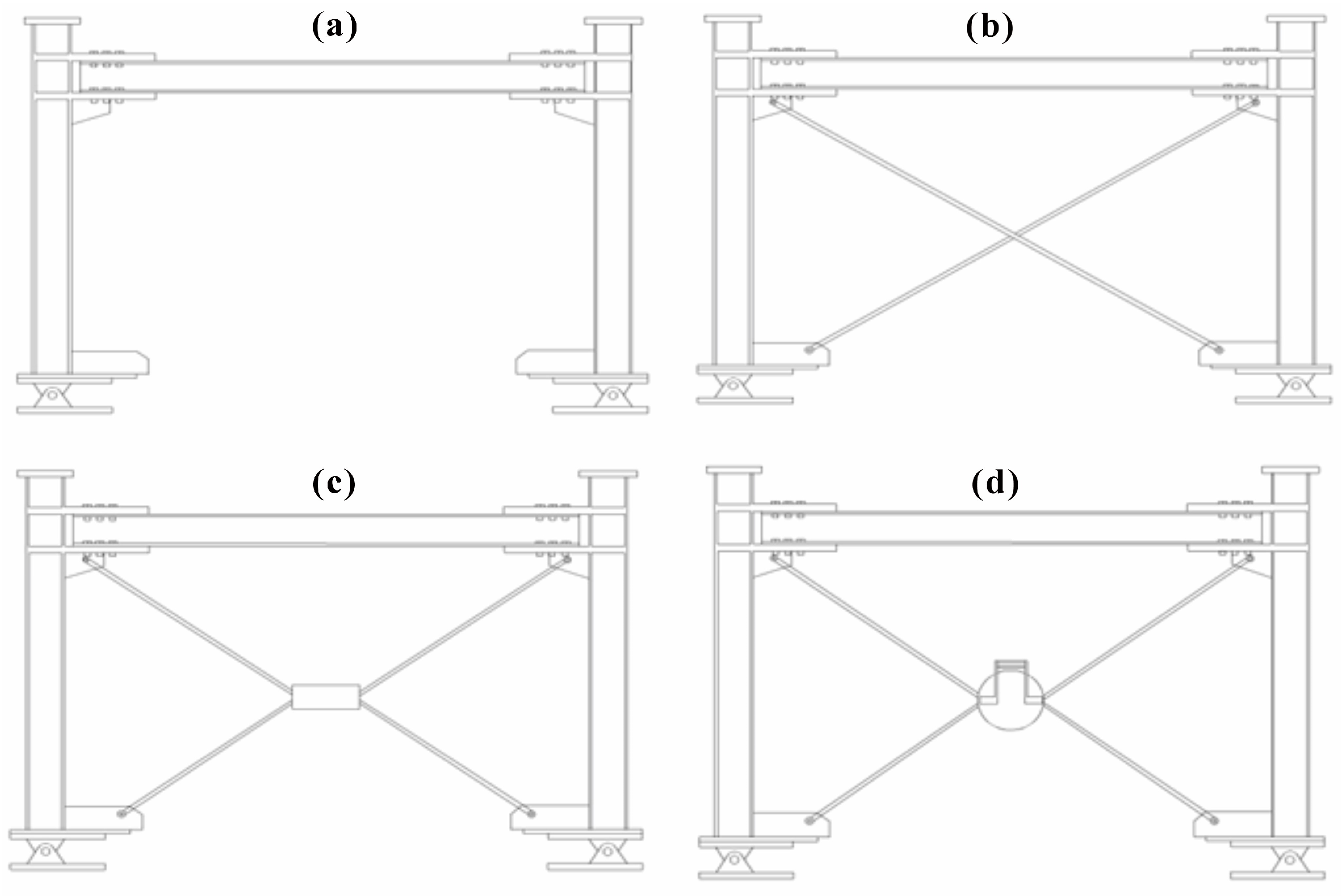
Numerical studies were conducted on four distinct frame configurations: (1) a rigid steel frame without braces and with Bolted Flange Plate (BFP) connections; (2) a rigid steel frame with cross-cable bracing; (3) a rigid steel frame with cable bracing and a central cylinder; and (4) a rigid steel frame with cable bracing and an optimized rotational friction damper. By comparing these models, this study provides new insights into the behavior of frames with varying bracing and damping configurations, revealing the advantages of the optimized rotational friction damper in enhancing seismic performance. This work contributes a practical, optimization-based framework for pretensioning in cable-braced frames, distinguishing it from previous studies and advancing the design of resilient, energy-dissipative structures.
2. Description of the Damper
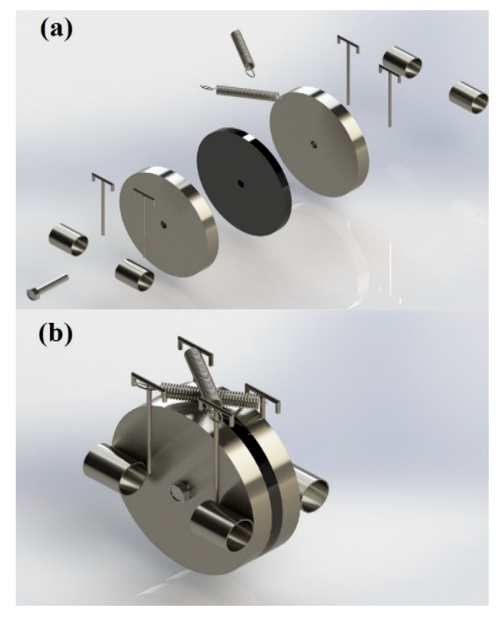
A rotational friction damper (
Figure 1) is a mechanical device that absorbs and dissipates energy in rotating systems. It is often employed in various engineering applications to dampen vibrations, reduce noise, and enhance system stability. The working principle of a rotational friction damper involves converting kinetic energy into heat through the frictional resistance between its components, thus slowing down the rotation of the system. A rotational friction damper’s effectiveness depends on factors such as material properties, surface roughness, and the contact force between the surfaces experiencing friction. By adjusting these parameters, engineers can tune the damping characteristics of the damper to meet specific requirements for a given application. Rotational friction dampers are commonly used in precision machinery, automotive suspension systems, and wind turbine blades to minimize unwanted oscillations and ensure smoother operation. Overall, rotational friction dampers play a crucial role in enhancing the performance and longevity of rotating systems by absorbing excess energy and minimizing wear and tear on mechanical components. Their ability to control vibrations and manage energy dissipation makes them valuable tools in various industries where precision, stability, and efficiency are paramount. As technology advances, further research and development in the field of rotational friction dampers are likely to lead to even more sophisticated and effective damping solutions in the future. When a lateral force is applied to the rigid steel frame, the components of the rotational friction damper are activated and resist the lateral force. Conversely, when the lateral force reverses direction, the damper rotates in the opposite direction and resists the reversed lateral force. Regardless of the direction in which the lateral force is applied, the rotational friction damper resists in the opposite direction.
3. Working Mechanism of RFD
In a previous study by Hou and Tagawa [
18], a system involving a cable brace with a central cylinder was investigated for strengthening rigid steel frames against lateral loads using a damper. In this system, the cable braces initially do not engage with the rigid frame at the start of each lateral loading period, leading to improved seismic behavior of the frame being solely dependent on the brace’s resistance against lateral loads. To enhance the seismic performance of the steel rigid frame, it was suggested to increase the brace’s contribution to the frame’s lateral resistance without altering the frame’s ductility. The impact of these modifications on the system’s seismic response needed to be evaluated under stable circumstances.
Therefore, this research proposed and assessed a cable bracing system incorporating a new rotational friction damper (RFD) under cyclic loading conditions. The results were compared with those of other cable-braced frames to analyze the effectiveness of the RFD in improving the seismic behavior of the rigid steel frame.
The reason for using the cross-cable brace to improve masonry buildings is reasonable cost, high tensile strength, low weight, resistance to corrosion and abrasion, durability and long life of the cable, easy and quick installation, and not occupying much space. Cross-cable braces have weak points. Therefore, many efforts have been made to improve the performance of crossed-cable braces. In this regard, in this research, by making changes in the cross-cable braces and using the disk, it has been tried to reduce the disadvantages and improve this system compared to other similar systems. The use of a disc increases the length of cables from the case of cross cable braces; as a result, under the effect of side loading and lateral position of the frame, no cable is loosened and is not removed from the assembly, and the ductility of the brace system increases.
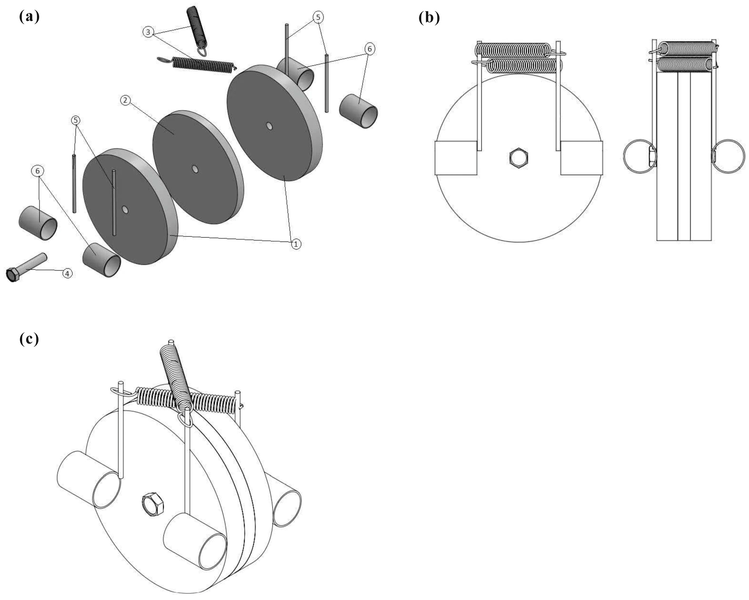
In order to increase the frictional resistance in this type of damper and to increase the shear resistance of the cylinder, a disc has been replaced. Also, it has helped to increase the friction and damping of the system by placing the rubber between the two layers. The damping system investigated in this research (
Figure 2) is a rotational friction damper that consists of steel discs (1), friction disc (2) rubber material, tension spiral springs (3), middle shaft (4), spring connection bases (5), and cylindrical cylinders (6), which are all connected to the mentioned disks.
The mechanism of a rotational friction damper involves converting mechanical energy into heat through the process of friction between two contact surfaces—one fixed and the other connected to the rotating shaft. As the rotating shaft turns, the relative motion between these surfaces generates frictional forces that resist the movement, leading to energy dissipation and heat generation. This heat is typically dissipated into the surrounding environment through conduction, convection, or radiation. The damping effect of a rotational friction damper is achieved by reducing the amplitude of vibrations and oscillations in the rotating system. By dissipating energy through friction, the damper improves the machinery’s stability, performance, and longevity by mitigating the harmful effects of dynamic loads and vibrations. The detailed mechanism of a rotational friction damper revolves around leveraging frictional forces to dissipate energy as heat, thereby dampening vibrations and enhancing the overall performance and reliability of rotating systems in various industrial settings. In this research, two steel discs and one disc made of rubber material are cross-connected by means of a middle shaft and two tension spiral springs. Additionally, this damper is installed inside the moment steel frame by means of two cables.
4. Verification of Modeling
In this work, an analysis of experimental validation is performed using ABAQUS software, version 2023. The experimental setup consists of a rigid steel frame with column and beam members made from H-150 × 150 × 7 × 10 sections (steel grade: SN400B), connected using bolted T-stubs cut from H-300 × 150 × 6.5 × 9 (steel grade: SS400). During testing, only the T-stubs exhibited plastic deformation, while the column and beam members remained elastic, ensuring controlled deformation behavior. The frame has an overall width of 2200 mm and a height of 1847 mm, with a distance of 1568 mm from the base to the beam-to-column connection. The bracing members consist of 10 mm diameter stainless steel (SUS316) strand (7 × 19) cables with a yield load of 57.9 kN and an ultimate load of 60.2 kN, providing the necessary tensile strength to simulate lateral load resistance. Reinforcement plates (PL22) were used at the top and bottom connections, with additional filler plates (PL1.6 and PL16) positioned to strengthen joints and maintain structural integrity. Bolted connections (F10T M20) are spaced 48 mm apart to securely fasten the critical connections, while support plates (PL16) at the base provide stability and prevent out-of-plane movement.
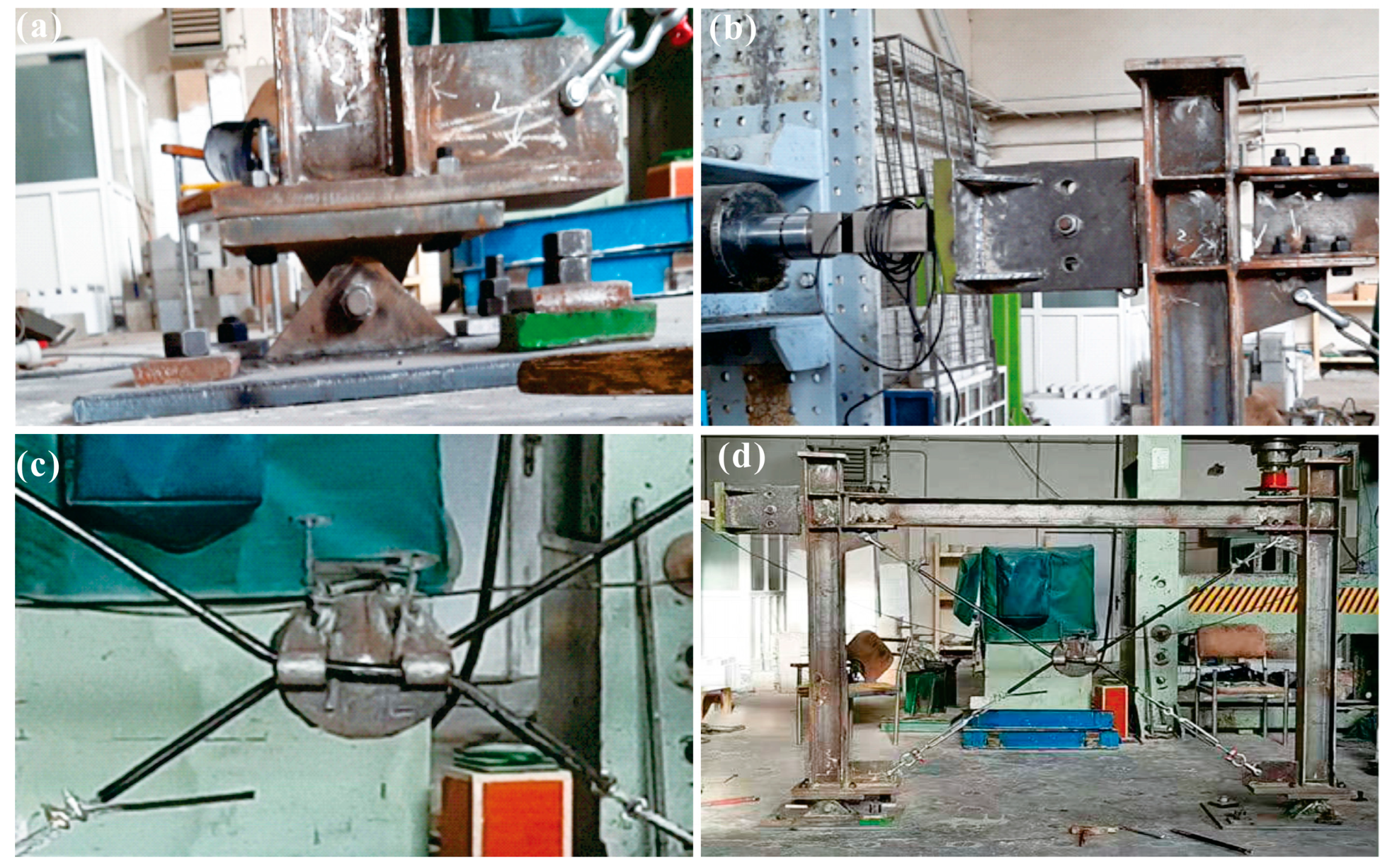
In all laboratory models, the frame is connected to the rigid floor with two articulated supports, and in order to prevent out-of-plane instability of the samples, the said support is also reinforced with steel stiffeners. The frame is connected to the hydraulic jack through another hinged support, which is installed at the meeting place along the axis of the beam and the column, and at its opposite point on the other side of the beam, the equipment for measuring the displacement of the frame is installed.
The details of the experimental model are shown in
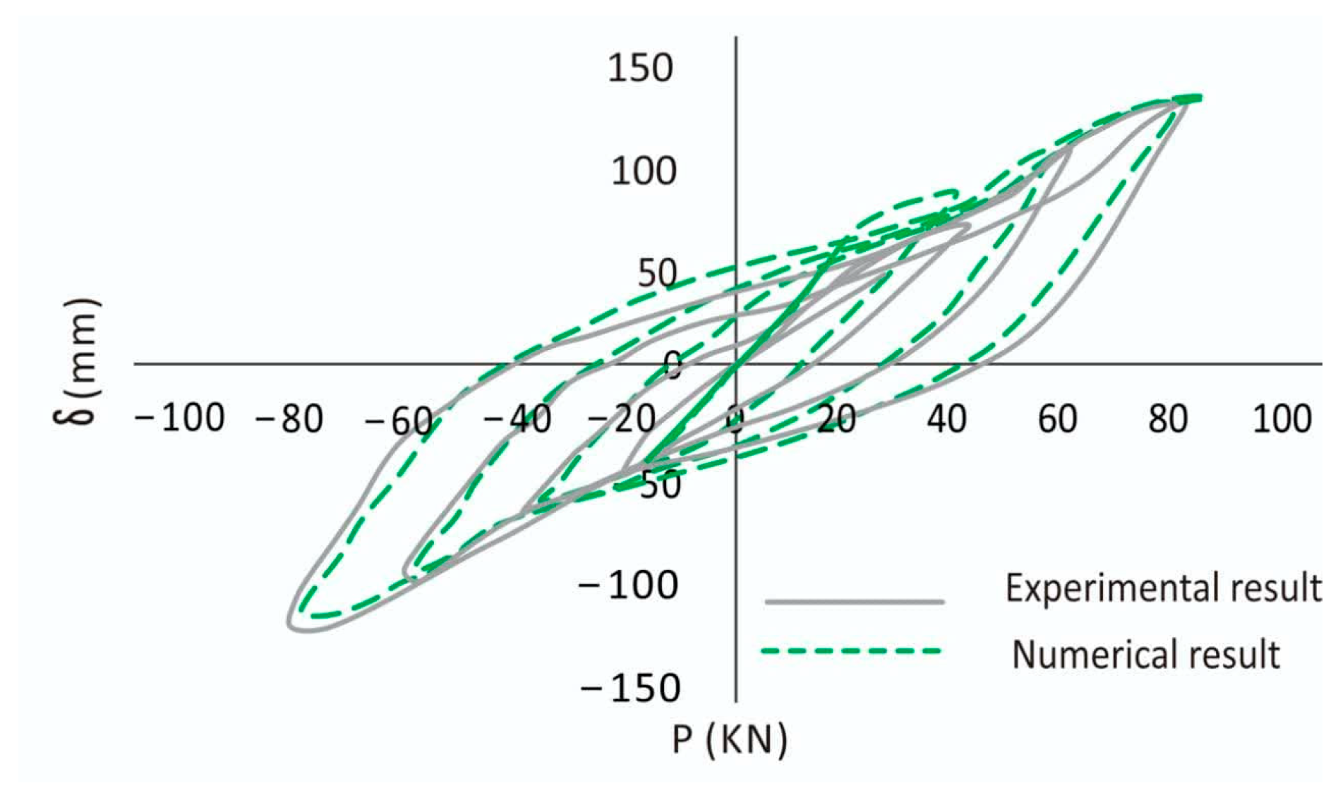
Figure 3. Since the experimental specimen was tested under cyclic loading (
Figure 4), the hysteresis curves of the experimental test results and FE simulation were compared and agreed upon. The FE results were thus confirmed to verify the modeling.
The area enclosed by each loop of the hysteresis curve is proportional to the energy dissipated by the RFD during each loading cycle. The fact that both experimental and numerical results show wide loops suggests that the damper is effectively dissipating energy, which is essential for controlling the response of structures under dynamic loads, such as earthquakes. The maximum forces and displacements (approximately ±150 kN and ±150 mm) indicate the damper’s capacity to resist high loads while undergoing large displacements. The symmetry of the loops suggests that the damper’s behavior is consistent under both positive and negative cycles, which is crucial for maintaining structural stability during bi-directional or reversing load conditions. There is some discrepancy between the experimental and numerical results at higher displacements and forces, where the experimental curve tends to be slightly flatter compared to the numerical one. This may be due to complexities in friction behavior that are difficult to capture precisely in numerical models, such as the degradation of friction surfaces or slight variations in contact conditions during testing.
5. Description of the Numerical Models
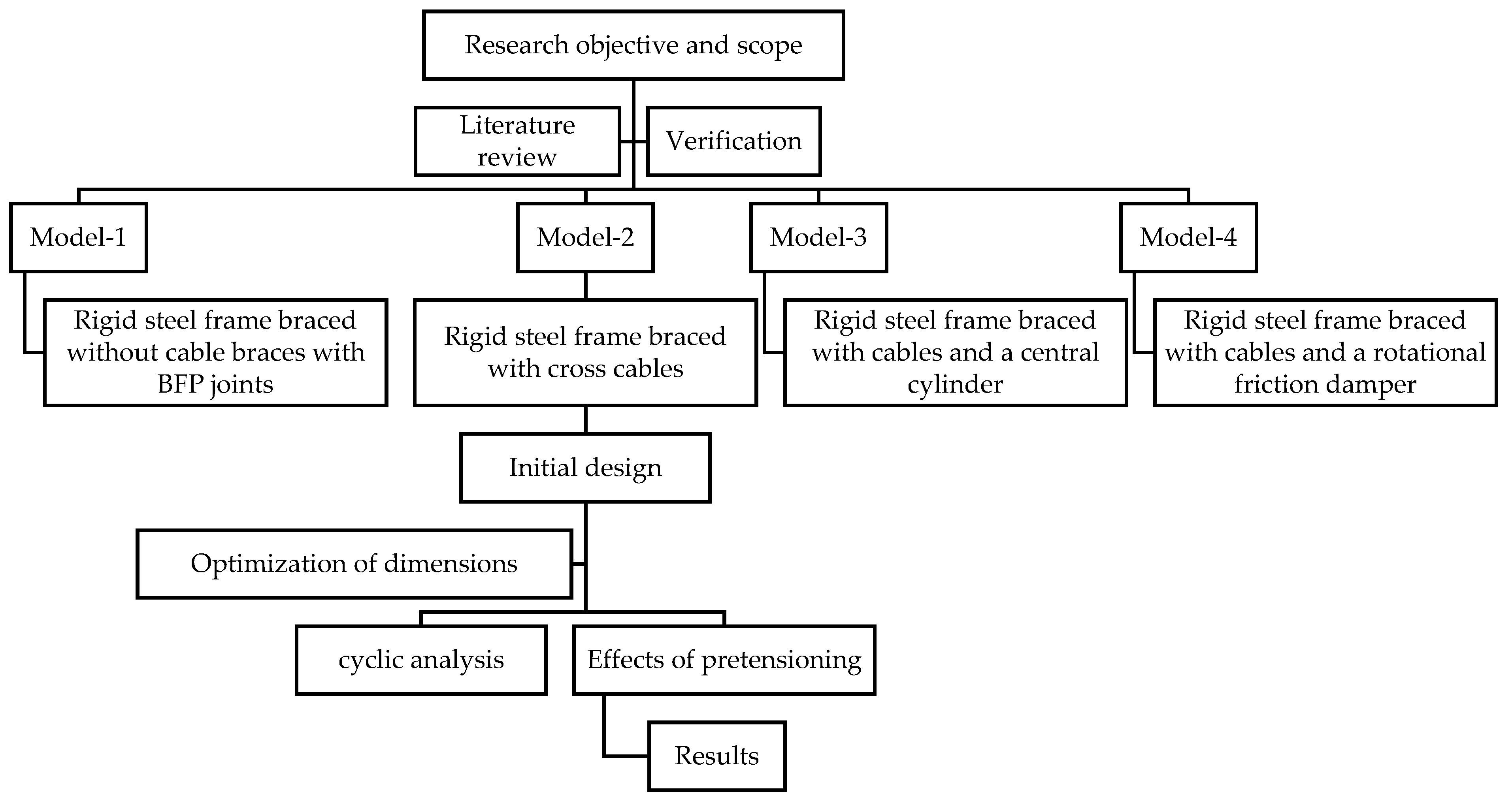
The main assumption in the modeling process for the rehabilitation braced system is that the bracing will enhance the lateral resistance of the system, curbing unacceptable story drift. It is also expected to improve the structure’s energy absorption capacity. To simplify the modeling process, certain assumptions have been made: the rigid frames are made of isotropic steel; axial strain in cables begins at their ultimate length; columns do not fail or buckle in any loading cycles; yielding and failure are prevented by imposing maximum loading limits; and stress concentrations at brace cable connection joints are considered negligible. These assumptions aim to facilitate the evaluation of the system’s seismic behavior and energy absorption properties under the cable-braced steel rigid frame system influence of the RFD (
Figure 5).
In this study, the structural frame was modeled using hexahedral C3D8R solid elements, chosen for their effectiveness in capturing complex stress distributions under seismic loading. Cable braces were modeled with B31 beam elements to simulate tensile behavior with minimal computational demand. Material models for the steel frame and cables followed an elastic–plastic model with strain hardening, using typical structural properties: Young’s modulus of 210 GPa, yield strength of 250 MPa, and Poisson’s ratio of 0.3. The friction damper was represented with a frictional interface, using a friction coefficient (μ = 0.3) to simulate energy dissipation. Mesh sizes were carefully selected to balance accuracy and computational efficiency, with 10 mm elements for the frame and finer, 5 mm elements applied near high-stress areas, such as damper interfaces, based on a convergence study that confirmed these sizes as optimal for capturing stress gradients effectively.
The modeling approach was implemented in ABAQUS (version 2023) with a time-history analysis to simulate realistic seismic loading conditions where displacement-controlled ground motion input was applied incrementally at the base of the frame to replicate cyclic loading effects. Fixed boundary conditions were applied at the frame base to prevent translational and rotational movement, simulating attachment to a rigid foundation, while hinge connections were used for cables to allow realistic rotational behavior at joints. Convergence analysis, employing a Newton–Raphson iterative method with a tolerance of 0.01, ensured model stability and accuracy under nonlinear loading conditions, confirming that the model reliably represents the seismic performance of the frame-braced system.
The design parameters and modeling decisions were guided by engineering standards, such as Eurocode [
36] and ASCE 7 [
37], including considerations for target displacements, energy dissipation, and maximum allowable drifts. The structural system comprises a steel moment frame with cable bracing and a rotational friction damper, with overall frame dimensions—including height, span length, and cross-sectional properties of beams, columns, and braces—modeled to reflect realistic structural configurations. In terms of material behavior, the steel was modeled elastoplastically with strain hardening, and simplifications, such as ignoring temperature effects, were made to streamline the analysis while maintaining accuracy for seismic scenarios. Validation of the numerical model was achieved by comparing results with experimental data and findings from previous studies with key indicators, such as hysteresis curves and energy dissipation, closely aligning with reference results. Although certain structural components and connection details were idealized to reduce computational complexity, these simplifications had minimal impact on the primary structural response, allowing efficient evaluation of the frame-braced system’s seismic performance.
In this section, four models were built, and the seismic behavior under cyclic loading conditions is studied in those models. The models that are studied are mentioned in
Table 1Structural damping in this study is primarily handled through frictional damping provided by the rotational friction damper integrated within the steel frame. The damper’s frictional interface was designed to absorb and dissipate seismic energy, which reduces the need for additional inherent damping in the structural model itself. Energy dissipation occurs as relative motion between damper components produces frictional resistance, with a specific friction coefficient (μ = 0.3) that determines the level of damping force. This frictional mechanism effectively captures the damping behavior under cyclic loading, and only minimal inherent damping was included in the frame to reflect its intrinsic energy loss capacity.
The schematic representation of the mentioned models is illustrated in
Figure 6. Young’s modulus of steel discs has been 1500 times the modulus of mild steel to eliminate its deformation. The material property of the cylinder steel damper is used based on Azarkhosh et al. [
38], and Poisson’s ratio of materials is 0.3. Other material property of the damper is presented in
Table 2.
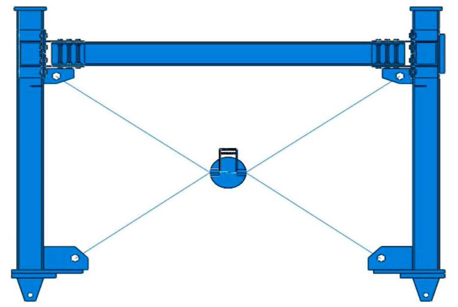
The models were subjected to cyclic loading using a single loading pattern, and the drift of the frames against lateral loads was measured and recorded in all loading cycles. Subsequently, the data were analyzed, and results were presented in the form of hysteresis diagrams. The maximum drift values of the frames and the energy absorbed by the frames under the same loading conditions were determined. The seismic performance of the various models was evaluated, and the optimal model was identified based on the results obtained from the analysis.
Figure 7 shows the assembly module of the steel moment frame with a rotational friction damper, which is modeled in ABAQUS (version 2023).
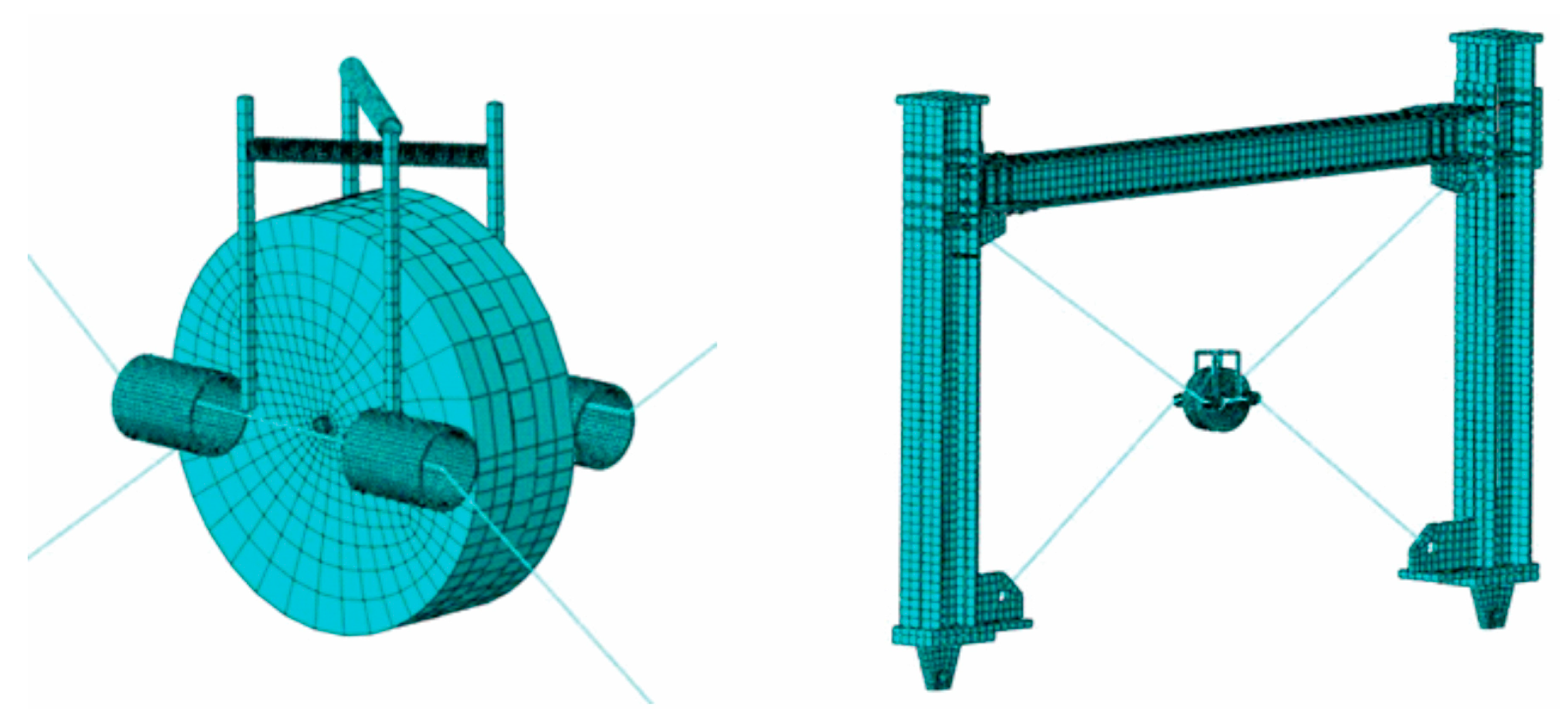
The elements used for the beam, column, and connecting components are the hexahedral type C3D8R with reduced integration and eight nodes, linear order (geometric order linear), mesh type (structured HEX) with standard elements, and 3D stress analysis. This type of meshing is suitable for symmetrical components. The cable is modeled with an element of the wire-B31 type with two nodes. The meshing of the frame and damper is shown in
Figure 8.
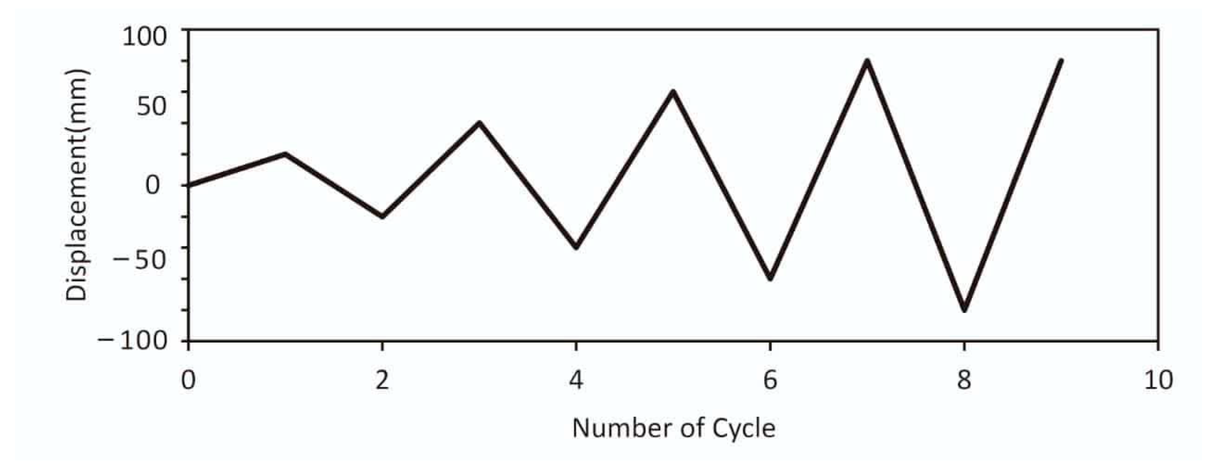
Cyclic loading was applied to the models using a quasi-static method employing displacement control.
Figure 9 shows the loading protocol applied to all models. During this stage, loads and boundary conditions were imposed on the finite element model in ABAQUS software (version 2023). The loading was cyclic with a displacement with progressively increasing amplitude.
5.1. Initial Design of the Model
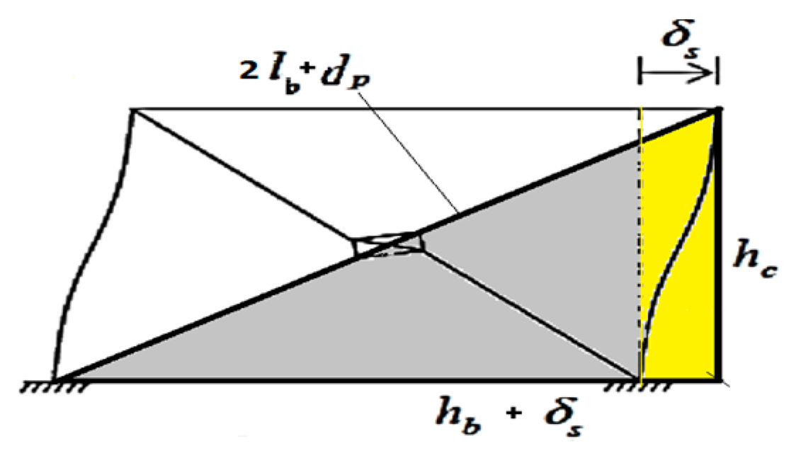
In the presented model, as illustrated in
Figure 10, the lateral displacement of the frame (
) when the bracing member is activated depends on the dimensions of the frame and disk and is calculated from the Equation (1):
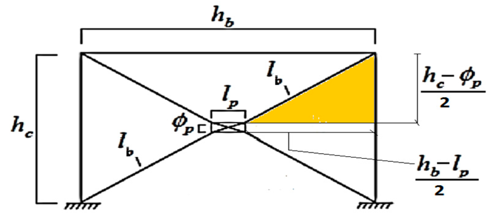
The cable bracing system with the disc is presented as a lateral bracing system for strengthening and improving the seismic response of the steel flexural frame (
Figure 11). This system’s performance is based on lateral reinforcement with increased stiffness to prevent large displacements of the moment frame and the loss of absorbed energy.
To control the degree of stiffness in this system and limit the maximum lateral displacement of the moment frame to the desired level, the brace cables must be tensioned before the lateral loading of the moment frame and during installation. Applying this prestress will obviously change the amount of energy absorption by the system.
One of the fundamental features of this system is maintaining the amount of absorbed energy and preventing the negative effects caused by this drop in the seismic response of the moment frame. Therefore, the effect of prestressing in the cables on the seismic response of the moment frame based on changes in the amount of absorbed energy should be investigated.
5.2. Optimization of Dimensions
After modeling the frame in the ABAQUS software (version 2023), the initial design of the structural elements was conducted. The objective was to determine the optimal dimensions of the friction damper using the gray wolf optimization algorithm and reduce the displacement of the upper level.
The gray wolf optimization algorithm is a nature-inspired metaheuristic algorithm developed by Mirjalili [
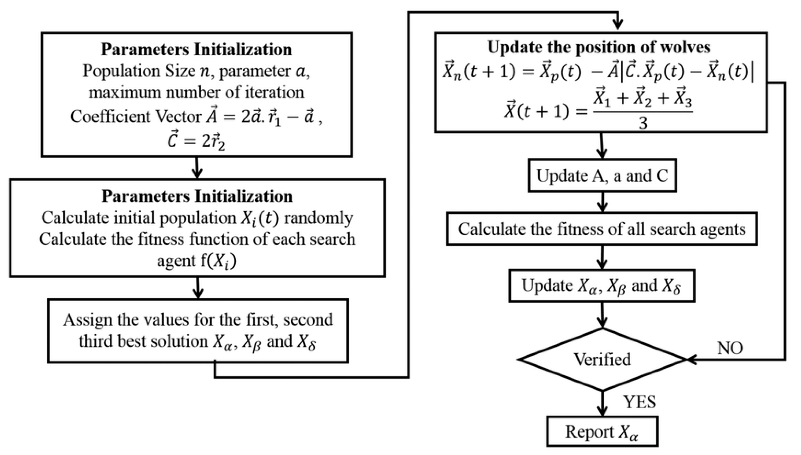
39] that mimics the leadership hierarchy and hunting mechanism of gray wolves in nature. This algorithm is known for its efficiency in handling complex optimization problems with minimal parameter tuning. The gray wolf algorithm employs three main operators—encircling, hunting, and attacking prey—to simulate the social dominance hierarchy among wolves. These operators help in balancing exploration and exploitation of the search space, making the algorithm suitable for determining optimal damper dimensions in structural engineering applications. Finally, the flowchart of the gray wolf algorithm can be considered in
Figure 12. This flowchart will only work by specifying the values of the A and C vectors.
After several times of execution and trial and error by the gray wolf algorithm, the optimal values for the number of wolves, the number of repetitions, and the penalty coefficients were considered equal to 1000, 30, and 1011, respectively. The optimal geometric dimensions and mechanical characteristics for the proposed friction-damping system are determined in
Table 3:
6. Results and Discussion
6.1. Proposed Rotational Friction Damping System
The lateral loading process was applied to the rigid steel frame braced with cable and a rotational friction damper. Before the loading commenced, the frame had zero initial drift, and the columns were in a vertical extension while the beam was completely horizontal. The rotational friction damper was assumed to be stable at the frame centroid according to static equilibrium.
As the cyclic loading was applied to the model of a rigid steel frame braced with cable and a rotational friction damper, the following results were concluded:
In the first cycle, with a drift of 1.5%, the damper remained inactive as the frame passed the cycle without activation.
In the subsequent cycle, with a drift of 3%, the cable braces started contributing to the frame’s lateral resistance, and the damper began absorbing energy by rotating around an axis perpendicular to the frame plane.
With a drift of 4.5% in the third cycle, the brace’s participation in lateral resistance increased, and the damper absorbed more energy as the steel discs rotated and the spring stretched within the system.
As the drift reached 6% in the final cycle, the braces bore almost all the force for lateral resistance, and the rotational friction damper absorbed maximum energy as the steel discs reached their maximum rotation relative to each other.
The operational mechanism of the rotational friction damper in the rigid steel frame with cable bracing involves the following steps:
Cable braces enhance frame lateral resistance, reducing drift initially.
Increased lateral forces cause rotation of the central core, allowing the frame to drift without compromising ductility.
Rotation of the central core leads to internal components of the damper rotating relative to each other, enhancing energy absorption in the system.
The loading process was terminated to prevent connection damage as the frame approached its maximum capacity, with the displacement reaching approximately 80 mm.
In the fourth step of the process, the lateral load direction was reversed, causing the central components of the rotational friction damper to rotate in the opposite direction compared to the previous step. Due to the tensile force effect on the springs within the damper, the system returned to its initial state and rotated in the opposite direction due to the cyclic loading effect. This reversal in the rotation direction further increased energy absorption in the system. This cyclic process continued throughout the loading period by repeating loading cycles continuously.
6.2. Comparison of Models
Similar procedures were conducted for models of unbraced rigid steel frame (Model 1), rigid steel frame braced with cross cable (Model 2), and rigid steel frame braced with cable and central cylinder (Model 3). The results obtained were analyzed and presented in hysteresis graphs.
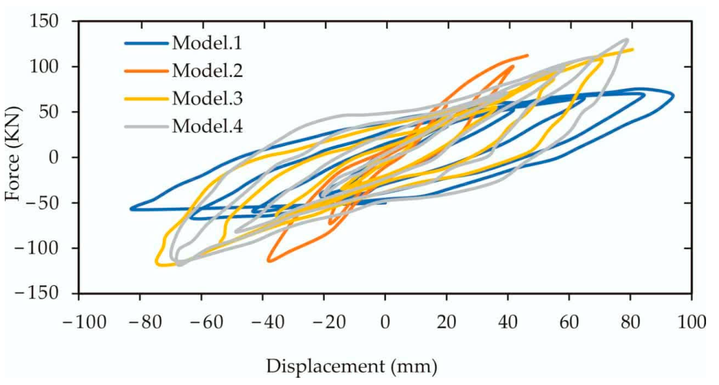
The hysteresis charts of the four examined models are illustrated in
Figure 13. It is evident from the results that the symmetry of diagrams for Model 1 and RFD is higher compared to the diagram of Model 3 and significantly higher than the diagram of Model 2, indicating that the behavior of the bracing systems in Model 1 and RFD is more uniform against lateral loads. Moreover, the number of cycles until failure is greater in diagrams for Model 3 and RFD compared to diagram Model 2.
A key advantage of the rigid steel frame braced with cable and rotational friction damper is that, as observed from the hysteresis diagrams, the area under the hysteresis curve for this model is larger than that of Model 1 and significantly larger than Model 2 and Model 3. This suggests that the bracing system in RFD is less slender and will fail later than the other models. Additionally, the rigid steel frame braced with cable and a rotational friction damper exhibits considerable energy absorption compared to other models due to the significantly larger area under the hysteresis curve.
Figure 14 presents a comparative diagram of the four models. The rigid steel frame braced with cross cable exhibits fewer cycles than the other models, indicating an earlier failure. The area under the hysteresis curve of the rigid steel frame braced with cable and a rotational friction damper is larger than that of model 1 and model 3. The data and results depicted highlight the rigid steel frame braced with cable and rotational friction damper’s performance in terms of ductility and energy absorption. The peak lateral load-carrying capacities (
) and ultimate displacements (
) for each model are summarized in
Table 4. In this study,
represents the maximum lateral force that each model can withstand before reaching its ultimate displacement,
. These values reflect the load-carrying capacity of each frame configuration under cyclic loading.
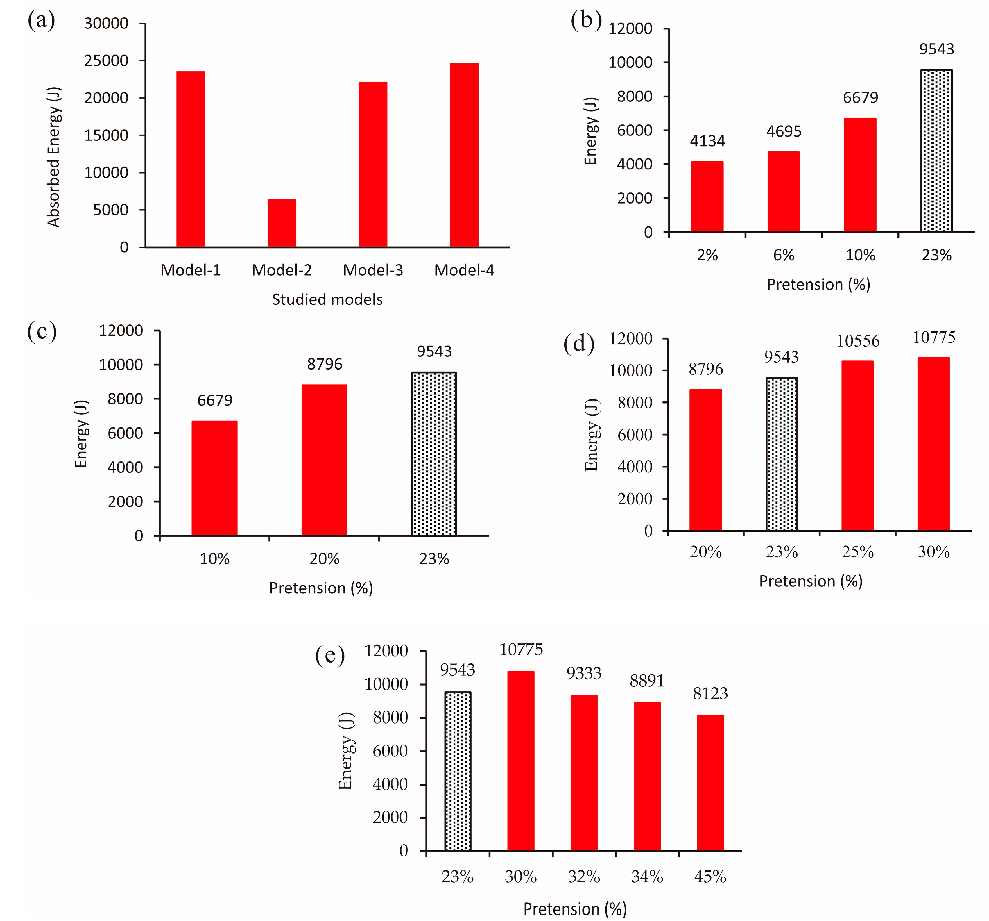
The cumulative absorbed energy in the different models is a crucial parameter for assessing their performance. In
Figure 15, the cumulative absorbed energy in the unbraced rigid steel frame, rigid steel frame braced with cross cable, rigid steel frame braced with central cylinder, and rigid steel frame braced with cable and rotational friction damper is presented as 23.6, 6.4, 22.1, and 24.6 kJ, respectively.
The percentage of variation in energy absorption for the rigid steel frame braced with cross cable, rigid steel frame braced with central cylinder, and rigid steel frame braced with cable and rotational friction damper compared to the unbraced rigid steel frame are −7.3%, −6%, and +4.4%, respectively. These values indicate that the energy absorption in the rigid steel frame braced with cable and rotational friction damper exhibits a more positive performance than the other models.
In addition to the analysis conducted on pretension levels, further details on the structural effects of the rotational friction damper, including variations in damping percentage and effective stiffness, are provided in the
Supplementary Materials.
6.3. Effects of Pretension on Both Cables
In this section, the impact of pretensioning on the seismic response of a moment frame with a central damper is analyzed. Pretensioning levels of 10%, 20%, and 30% are applied to both cables. A comprehensive evaluation of the structure’s seismic performance is then conducted based on lateral stiffness and absorbed energy parameters. Various pretension levels are compared with a validated model for a detailed assessment. The upcoming graph illustrates the analysis results of the specific models alongside a validated model with approximately 23% pretensioning.
6.3.1. Pretension (2% to 10%)
To further investigate the factors influencing the seismic performance of the moment frame, pretension levels ranging from 2% to 10% of the cables’ tensile capacity (CTC) are applied. In addition to the 10% pretension, modeling includes also 2% as well as 6% pretension levels, and the results are presented in
Figure 15b.
Increasing the pretensioning force up to 10% of CTC enhances the system’s initial stiffness and expands the area enclosed within the hysteresis curve, resulting in greater energy absorption. Conversely, reducing the pretensioning force below 2% of CTC causes the frame’s behavior to resemble that of a frame braced with cross-cable braces but without a central damper. This leads to a decrease in the inner surface of the hysteresis curve and the initial stiffness of the braced frame compared to other scenarios. In such cases, the central damper may be positioned diagonally along the frame’s diagonal due to cable slackening and gravity influence, impairing its normal function.
6.3.2. Pretension (10% to 20%)
When pretension levels between 10% and 20% of CTC are applied, the cumulative absorbed energy of the models increases with a 20% pretensioning force, shown in
Figure 15c.
Increasing the pretensioning force from 10% to 20% of each cable’s tensile capacity results in higher initial frame stiffness. However, the rate of stiffness increase is lower when compared to the scenario involving pretension levels of 2% to 10% of CTC. Additionally, the area enclosed within the hysteresis curve also increases in this case compared to the previous condition.
6.3.3. Pretension (20% to 30%)
Moving on to applying pretension levels between 20% and 30% of CTC, the behavior of the moment frame with the cable brace system and the central damper is studied by applying pretension levels of 23%, 25%, and 30% of CTC. The subsequent graphical representation illustrates the analysis results of these models alongside a validated model with approximately 23% pretensioning (
Figure 15d).
In the hysteresis diagram of models with pretension levels ranging from 20% to 30%, it is evident that the initial stiffness of the frame, the area enclosed within the hysteresis curve, and the amount of absorbed energy increase as the pretensile force of the cables is raised. However, the rate of increase in these parameters is lower compared to models with pretension levels of 10% to 20%. Specifically, the energy absorbed in models with 25% to 30% pretension only increases by 220 J.
6.3.4. Pretension (More than 30%)
Further applying pretension levels exceeding 30% of CTC, modeling is conducted with pretension levels of 30%, 32%, and 34% of each cable’s tensile capacity. Additionally, to further explore the system’s behavior under higher pretensioning forces, a sample with a pretensioning force equal to 45% of the brace cable’s tensile capacity is analyzed. The results of these models are presented in
Figure 15e for a comprehensive understanding of the system’s behavior under larger pretensioning forces.
The results presented in
Figure 15e illustrate that increasing the pretensioning force from 34% to 45% leads to a minimal increase in the stiffness of the braced frame. Unlike the previous scenarios where the enclosed area inside the hysteresis curve increased with higher pretensioning levels, in this case, as the percentage of pretensioning increases, the absorbed energy actually decreases.
6.4. Pretension Effect on a Single Cable
For further examination of pretensioned models in one of the cables, where one cable is directly pretensioned by 10%, 20%, or 30% of its tensile capacity, the lateral position of the frame and the period of the central damper are altered. Assuming that the frame remains in the same lateral position after applying the tensile force to one cable and the central damper is statically balanced horizontally, the internal forces in the other cable are expected to be identical. Consequently, the seismic behavior of this frame with the same pretensioning percentages is anticipated to be similar to the previously investigated models.
Figure 16 compares the hysteresis curves obtained from experimental testing with those from the numerical model under different pretensioning conditions. This comparison serves to verify the accuracy of the numerical model, showing that its predictions align closely with experimental results. These diagrams show the hysteresis curve of the pretensioned model, with both cables denoted as “B,” along with the hysteresis diagrams of the right and left cables’ pretensions represented by “R” and “L,” respectively.
The hysteresis curves of the pretensioned models show slight variations when force is applied to the left and right cables. Uncertainties in the modeling process likely cause this small difference.
6.5. Effect of Pretension on Seismic Response
This section provides insights into the impact of pretensioning on the seismic response of a steel moment frame with a cable brace and central damper. Results showing the percentage of cumulative absorbed energy and force in target displacement for all pretensioning levels will be presented to offer a comprehensive understanding of the system’s behavior.
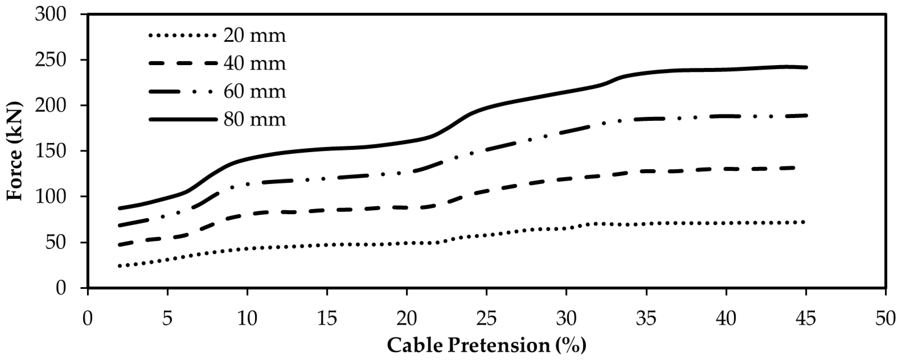
In particular, the force required to induce specific displacements in the braced moment frame, known as the force in moving the target, is a critical parameter influencing the seismic response of the system. This parameter essentially reflects the lateral stiffness of the braced frame and is crucial for accurately assessing the seismic performance of the structure.
The results in
Figure 17 indicate that as the pretensioning percentage of the brace cables increases, the force in moving the target also rises. However, the rate of increase varies across different pretensioning intervals. To comprehensively illustrate these changes, the analysis results of ten models with varying pretensioning percentages will be consolidated and presented on a single graph to show the evolving dynamics.
Figure 18 shows that as the pretensioning force increases, the force required to move the target also escalates. Within the 2% to 34% pretensioning range, for each one percent rise interval in pretensioning force, the force in moving the target increases by approximately 10%. Interestingly, beyond the 34% pretensioning level, the rate of increase diminishes significantly. For pretensioning levels of 34% and higher, every one percent increase in pretensioning force only leads to a marginal 0.1% rise in the force required to move the target. This trend is clearly depicted in the graph, where the slope approaches zero for pretensioning levels at or above 34%, indicating a minimal impact on the force in moving the target.
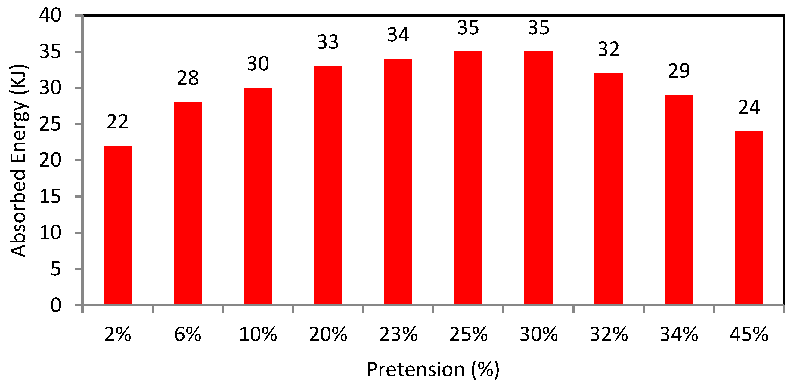
Based on the analysis of the percentage of absorbed energy in
Figure 19, it was observed that as the pretension in the brace cables increases, the absorbed energy initially rises before declining. The increased and decreased absorption energy rates vary across different pretensioning intervals. To provide a comprehensive view of these fluctuations, the results of the analysis of ten cases with varying pretensioning percentages have been graphed below for a detailed examination.
According to the results, it is evident that as the percentage of pretension in the cable braces increases, the percentage of absorbed energy also rises within the pretension range of 2% to 25%. However, in the range of 25% to 30% pretension, the absorbed energy remains relatively constant at 35%. Interestingly, for pretension exceeding 30%, the absorbed energy starts to decrease.
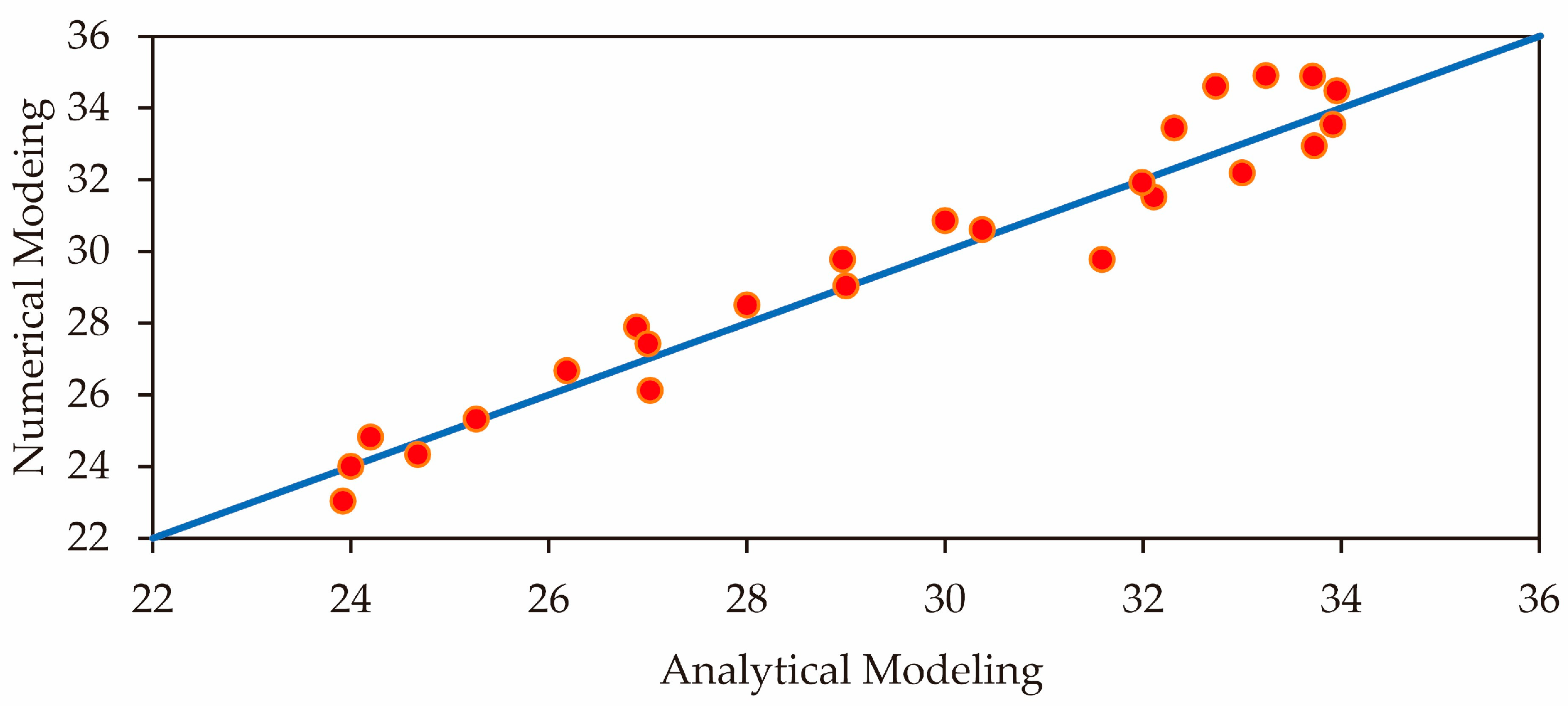
Overall, a simplified equation is proposed to obtain the amount of energy dissipation based on the amount of pretension:
where Ed is energy dissipation, and pt is pretension
While this expression accurately captures the relationship between pretensioning force and energy dissipation for the case examined, it is important to note that this relationship is specific to the configurations and conditions tested and may not be generalized to other structures or loading scenarios.
Verification of the proposed equation between numerical modeling and analytical modeling is shown in
Figure 20.
7. Conclusions
This study focused on enhancing the seismic resilience of steel moment frames equipped with bolted plate joints reinforced by cable braces and a central friction damper. By implementing an innovative design for a rotational friction damper and refining the structure of the cable braces with the inclusion of a central friction damper, the objective was to ensure that the cable braces could effectively resist lateral forces during the loading process. The cyclic loads generated by earthquakes exert pressure on the moment frame; therefore, improving the system’s energy absorption capabilities significantly contributes to the seismic fortification of steel moment frames. The main findings of the research include:
Increasing the tension in cable braces to 10% of the cable’s maximum strength initially stiffens the structure and allows it to absorb more energy. If the tension is reduced to below 2%, the brace’s performance is similar to that of a moment frame with cross cables, which lacks additional damping.
Raising the tension from 10% to 20% improves stiffness further, but the increase is not as significant as it was from 2% to 10%. The area under the hysteresis curve also increases, showing better energy dissipation.
Hysteresis diagrams for tension levels between 20% and 30% indicate that as tension increases, stiffness, hysteresis area, and energy absorption improve, though the improvements become smaller after 20%. Energy absorption rises by just 220 units when going from 25% to 30% tension.
Moreover, higher tension levels require more force to achieve lateral displacement. For tension levels between 2% and 34%, each 1% increase in tension needs about a 10% larger lateral force. Beyond 34% tension, this effect decreases, with each additional 1% requiring only a 0.1% increase in force, making it less significant.
As cable tension rises from 2% to 25%, the amount of energy absorbed also increases, stabilizing at around 35% between 25% and 30%. However, the absorbed energy then drops for tensions above 30%.
An equation has been created to estimate energy dissipation based on cable tension, showing that moment frames with rotational friction dampers perform better during seismic events than the other configurations studied.
The analysis of hysteresis diagrams indicates that the unbraced moment frame and the frame with cable braces and a rotational friction damper show more balanced behavior than those reinforced with cross cables when exposed to lateral forces.
The bracing system in the moment frame with cable braces and a rotational friction damper lasts longer before failing than the frame with cross cables.
Finally, the braced steel moment frame with a rotational friction damper has a larger area under the hysteresis curve, indicating that it is stronger and fails later than other frame configurations. This system also absorbs more energy, demonstrating better flexibility and energy dissipation performance than other structures.
Author Contributions
Conceptualization, D.S. and P.A.; methodology, P.A.; software, P.A.; validation, P.A., D.S. and A.I.A.; formal analysis, P.A. and S.A.A.M.; investigation, D.S.; resources, D.S.; data curation, S.A.A.M. and A.I.A.; writing—original draft preparation, D.S. and P.A.; writing—review and editing, D.S., P.A., S.A.A.M. and A.I.A.; visualization, P.A. and A.I.A.; supervision, D.S.; project administration, D.S.; funding acquisition, D.S. and A.I.A. All authors have read and agreed to the published version of the manuscript.
Funding
This research was funded by Researchers Supporting Project number (RSP2024R424), King Saud University, Riyadh, Saudi Arabia.
Data Availability Statement
The original contributions presented in the study are included in the article, further inquiries can be directed to the corresponding authors.
Conflicts of Interest
The authors declare no conflicts of interest.
References
- Hanson, R.D. Supplemental Damping for Improved Seismic Performance. Earthq. Spectra 1993, 9, 319–334. [Google Scholar] [CrossRef]
- Gattulli, V. Passive Energy Dissipation Systems in Structural Engineering; Soong, T.T., Dargush, G.F., Eds.; John Wiley & Sons: Hoboken, NJ, USA, 1999; Volume 34, pp. 65–66. [Google Scholar]
- Aiken, I.D.; Nims, D.K.; Whittaker, A.S.; Kelly, J.M. Testing of Passive Energy Dissipation Systems. Earthq. Spectra 1993, 9, 335–370. [Google Scholar] [CrossRef]
- Shen, K.L.; Soong, T.T.; Chang, K.C.; Lai, M.L. Seismic behaviour of reinforced concrete frame with added viscoelastic dampers. Eng. Struct. 1995, 17, 372–380. [Google Scholar] [CrossRef]
- Lu, Y.; Li, J.; Liu, B.; Chen, J.; Zhang, W.; Meng, Q. Study on the Vibration Isolation Performance of Sliding–Rolling Friction Composite Vibration Isolation Bearing. Buildings 2024, 14, 2053. [Google Scholar] [CrossRef]
- Thorburn, L.J.; Kulak, G.L.; Montgomery, C.J. Analysis of Steel Plate Shear Walls; Structural Engineering Report No. 107; Department of Civil Engineering, University of Alberta: Edmonton, AB, Canada, 1983. [Google Scholar]
- Bartera, F.; Giacchetti, R. Steel dissipating braces for upgrading existing building frames. J. Constr. Steel Res. 2004, 60, 751–769. [Google Scholar] [CrossRef]
- Aldea, S.; Bazáez, R.; Heresi, P.; Astroza, R. Effect of Bidirectional Hysteretic Dampers on the Seismic Performance of Skewed Multi-Span Highway Bridges. Buildings 2024, 14, 1778. [Google Scholar] [CrossRef]
- Pall, A.S.; Marsh, C.; Fazio, P.P. Friction Joints for Seismic Control of Large Panel Structures. PCI J. 1980, 38–61. [Google Scholar] [CrossRef]
- Pall Avtar, S.; Marsh, C. Response of Friction Damped Braced Frames. J. Struct. Div. 1982, 108, 1313–1323. [Google Scholar] [CrossRef]
- Pall, A.S.; Vézina, S.; Proulx, P.; Pall, R. Friction-Dampers for Seismic Control of Canadian Space Agency Headquarters. Earthq. Spectra 1993, 9, 547–557. [Google Scholar] [CrossRef]
- Balazic, J.; Guruswamy, G.; Elliot, J.; Pall, R.; Pall, A. Seismic Rehabilitation of Justice Headquarters Building, Ottawa, Canada. In Proceedings of the Twelfth World Conference on Earthquake Engineering, Auckland, New Zealand, 30 January–4 February 2000. [Google Scholar]
- Chandra, R.; Masand, M.; Nandi, S.K.; Tripathi, C.P.; Pall, R.; Pall, A. Friction-dampers for seismic control of La Gardenia towers south city, Gurgaon, India. In Proceedings of the Twelfth World Conference on Earthquake Engineering, Auckland, New Zealand, 30 January–4 February 2000. [Google Scholar]
- Hale, T.; Pall, R. Seismic upgrade of the Freeport water reservoir, Sacramento, California. In Proceedings of the Twelfth World Conference on Earthquake Engineering, Auckland, New Zealand, 30 January–4 February 2000. [Google Scholar]
- Wu, B.; Li, H.; Lin, L.; Shan, M. Seismic retrofit of a city hall in Northeast China with frictional energy dissipators. J. Build. Struct. 1998, 19, 28–36. [Google Scholar]
- Wu, E.; Hojatallah, A.; Zhou, G. Numerical Simulation Analysis of Energy Dissipation Capacity of Corrugated Steel Plate under Tension and Compression. Ing. Sismica 2022, 39, 16–42. [Google Scholar]
- Wu, B.; Zhang, J.; Williams, M.; Ou, J. Hysteretic behavior of improved Pall-typed frictional dampers. Eng. Struct. 2005, 27, 1258–1267. [Google Scholar] [CrossRef]
- Tagawa, H.; Hou, X. Seismic retrofit of ductile moment resisting frames using wire-rope bracing. In Proceedings of the 8th Pacific Conference on Earthquake Engineering, Singapore, 5–7 December 2007; p. 8. [Google Scholar]
- Hou, X.; Tagawa, H. Wire-rope bracing system with elasto-plastic dampers for seismic response reduction of steel frames. In Proceedings of the The 14th World Conference on Earthquake Engineering, Beijing, China, 12–17 October 2008; pp. 12–17. [Google Scholar]
- Zhang, J.; Qi, A.; Yang, M. Two-Stage Optimal Design Method for Asymmetric Base-Isolated Structures Subject to Pulse-Type Earthquakes. Buildings 2024, 14, 1728. [Google Scholar] [CrossRef]
- Fateh, A.; Hejazi, F.; Jaafar, M.S.; Karim, I.A.; Adnan, A.B. Design of a variable stiffness bracing system: Mathematical modeling, fabrication, and dynamic analysis. Soil Dyn. Earthq. Eng. 2016, 80, 87–101. [Google Scholar] [CrossRef][Green Version]
- Zhao, H.; Christopoulos, C. Seismic design and behavior of post-tensioned self-centering steel frames with web friction devices. J. Struct. Eng. 2016, 142, 04016001. [Google Scholar]
- Fateh, A.; Hejazi, F. Experimental testing of variable stiffness bracing system for reinforced concrete structure under dynamic load. J. Earthq. Eng. 2022, 26, 1416–1437. [Google Scholar] [CrossRef]
- Qiu, C.; Liu, J.; Du, X. Cyclic behavior of SMA slip friction damper. Eng. Struct. 2022, 250, 113407. [Google Scholar] [CrossRef]
- Veismoradi, S.; Yousef-beik, S.M.M.; Zarnani, P.; Quenneville, P. Development and parametric study of a new self-centering rotational friction damper. Eng. Struct. 2021, 235, 112097. [Google Scholar] [CrossRef]
- Bagheri, B.; Abbasi, M.; Sharifi, F.; Abdollahzadeh, A. Different attempt to improve friction stir brazing: Effect of mechanical vibration and rotational speed. Met. Mater. Int. 2022, 28, 2239–2251. [Google Scholar] [CrossRef]
- Feng, J.; Safaei, B.; Qin, Z.; Chu, F. Nature-inspired energy dissipation sandwich composites reinforced with high-friction graphene. Compos. Sci. Technol. 2023, 233, 109925. [Google Scholar] [CrossRef]
- Han, H.; Sorokin, V.; Tang, L.; Cao, D. A nonlinear vibration isolator with quasi-zero-stiffness inspired by Miura-origami tube. Nonlinear Dyn. 2021, 105, 1313–1325. [Google Scholar] [CrossRef]
- Latour, M.; Rizzano, G. Cyclic behavior and theoretical models of beam-to-column connections equipped with friction dampers. J. Earthq. Eng. 2012, 16, 540–571. [Google Scholar]
- Mualla, I.H.; Belev, B. Performance of steel frames with a new friction damper device under earthquake excitation. Eng. Struct. 2002, 24, 365–371. [Google Scholar] [CrossRef]
- Issa, A.; Chowdhury, A.; Tremblay, R.; Alam, M.S. Probabilistic fragility assessment of Self-Centering Braced Frames. In Proceedings of the 17th World Conference on Earthquake Engineering, Sendai, Japan, 13–18 September 2020. [Google Scholar]
- Zhang, A.-L.; Liu, X.-C.; Wang, Y.; Shang, Z.-X.; Yu, C.; Bai, Z.-X. Seismic behavior of an X-deployed cable-braced bolt-assembly steel frame. J. Constr. Steel Res. 2020, 170, 106132. [Google Scholar] [CrossRef]
- Ke, K.; Chen, Y.; Zhou, X.; Yam, M.C.; Hu, S. Experimental and numerical study of a brace-type hybrid damper with steel slit plates enhanced by friction mechanism. Thin-Walled Struct. 2023, 182, 110249. [Google Scholar] [CrossRef]
- Filiatrault, A.; Tremblay, R.; Kar, R. Seismic performance of friction-damped post-tensioned steel frames. J. Struct. Eng. 2000, 126, 280–287. [Google Scholar] [CrossRef]
- Petrini, F.; Magliulo, G.; Manfredi, G.; Mazzolani, F.M. Hybrid dampers for seismic control of steel frames: Theory and applications. Earthq. Eng. Struct. Dyn. 2016, 45, 1–20. [Google Scholar]
- EN 1998-1; Eurocode 8: Design of Structures for Earthquake Resistance—Part 1: General Rules, Seismic Actions and Rules for Buildings (EN 1998-1). European Committee for Standardization (CEN): Brussels, Belgium, 2004.
- ASCE/SEI 7-22; Minimum Design Loads and Associated Criteria for Buildings and Other Structures (ASCE/SEI 7-22). American Society of Civil Engineers (ASCE): Reston, VA, USA, 2022.
- Azarkhosh, H.; Wu, E.R.; Zhou, G.D.; Pouraminian, M.; Doroudi, A. Numerical study on seismic behavior of a novel wheel shaped damper. Ing. Sismica 2023, 40. [Google Scholar]
- Mirjalili, S.; Mirjalili, S.M.; Lewis, A. Grey wolf optimizer. Adv. Eng. Softw. 2014, 69, 46–61. [Google Scholar] [CrossRef]
Figure 1.
Schematic Detailing of RFD Components (a) isolated parts, (b) assembled device.
Figure 1.
Schematic Detailing of RFD Components (a) isolated parts, (b) assembled device.
Figure 2.
Dual rotational friction damping system: (a) comprising parts, (b) front view, (c) 3D view.
Figure 2.
Dual rotational friction damping system: (a) comprising parts, (b) front view, (c) 3D view.
Figure 3.
Experimental test setup: (a) Pinned support, (b) hydraulic jack, (c) rotational friction damper, (d) total frame.
Figure 3.
Experimental test setup: (a) Pinned support, (b) hydraulic jack, (c) rotational friction damper, (d) total frame.
Figure 4.
Validation of model based on experimental setup results.
Figure 4.
Validation of model based on experimental setup results.
Figure 5.
Flow chart of research objective.
Figure 5.
Flow chart of research objective.
Figure 6.
Schematic representation of the structural models: (a) Model 1, (b) Model 2, (c) Model 3, (d) Model 4.
Figure 6.
Schematic representation of the structural models: (a) Model 1, (b) Model 2, (c) Model 3, (d) Model 4.
Figure 7.
Steel moment frame equipped with RFD.
Figure 7.
Steel moment frame equipped with RFD.
Figure 8.
The meshing of the mode.
Figure 8.
The meshing of the mode.
Figure 9.
Loading protocol.
Figure 9.
Loading protocol.
Figure 10.
Frame after lateral displacement.
Figure 10.
Frame after lateral displacement.
Figure 11.
Frame with cable brace and disc.
Figure 11.
Frame with cable brace and disc.
Figure 12.
Flowchart of the gray wolf algorithm.
Figure 12.
Flowchart of the gray wolf algorithm.
Figure 13.
Hysteresis diagram: (a) unbraced rigid steel frame (Model 1), (b) rigid steel frame braced with cross cable (Model 2), (c) rigid steel frame braced with cable and central cylinder (Model 3), (d) rigid steel frame braced with cable and rotational friction damper (Model 4).
Figure 13.
Hysteresis diagram: (a) unbraced rigid steel frame (Model 1), (b) rigid steel frame braced with cross cable (Model 2), (c) rigid steel frame braced with cable and central cylinder (Model 3), (d) rigid steel frame braced with cable and rotational friction damper (Model 4).
Figure 14.
Hysteresis comparison of models.
Figure 14.
Hysteresis comparison of models.
Figure 15.
The absorbed energy of models with various pretensions: (a) cumulative absorbed energy, (b) up to 10%, (c) 10% and 20%, (d) between 20% and 30%, (e) more than 30% pretension.
Figure 15.
The absorbed energy of models with various pretensions: (a) cumulative absorbed energy, (b) up to 10%, (c) 10% and 20%, (d) between 20% and 30%, (e) more than 30% pretension.
Figure 16.
Comparison of hysteresis curves for models in left and right cables with various pretension: (a) 10% initial pretension, (b) 20% initial pretension, (c) 30% initial pretension.
Figure 16.
Comparison of hysteresis curves for models in left and right cables with various pretension: (a) 10% initial pretension, (b) 20% initial pretension, (c) 30% initial pretension.
Figure 17.
Force curve in moving the target with certain percentages of pretension.
Figure 17.
Force curve in moving the target with certain percentages of pretension.
Figure 18.
Cumulative energy absorption for different percentages of pretension.
Figure 18.
Cumulative energy absorption for different percentages of pretension.
Figure 19.
The curve of the percentage of absorbed energy for different percentages of pretension.
Figure 19.
The curve of the percentage of absorbed energy for different percentages of pretension.
Figure 20.
Verification of the proposed equation.
Figure 20.
Verification of the proposed equation.
Table 1.
Description of models.
Table 1.
Description of models.
| Model ID | Description |
|---|
| Model 1 | Rigid steel frame braced without cable braces with BFP joints |
| Model 2 | Rigid steel frame braced with cross cables |
| Model 3 | Rigid steel frame braced with cables and a central cylinder |
| Model 4 | Rigid steel frame braced with cables and a rotational friction damper |
Table 2.
Material property of the damper.
Table 2.
Material property of the damper.
| Steel Type | σy (MPa) | C1 (MP a) | γ2 (-) | C2 (MP a) | γ1 (-) |
|---|
| Q235B | 251.42 | 1300 | 8.1057 | 206 | 0 |
Table 3.
Optimal dimensions of friction damper components.
Table 3.
Optimal dimensions of friction damper components.
| Steel Springs |
| Length | 60 mm |
| Stiffness | 30 kN/m |
| Steel Cylinder |
| Length | 50 mm |
| Diameter | 40 mm |
| Steel Disc |
| Thickness | 25 mm |
| Diameter | 200 mm |
| Rubber |
| Thickness | 15 mm |
| Diameter | 200 mm |
Table 4.
Test Results.
| Model ID | | |
|---|
| MODEL 1 | 75.4 | 93.9 |
| MODEL 2 | 113.5 | 46.3 |
| MODEL 3 | 118.7 | 80.6 |
| MODEL 4 | 129.8 | 78.7 |
| Disclaimer/Publisher’s Note: The statements, opinions and data contained in all publications are solely those of the individual author(s) and contributor(s) and not of MDPI and/or the editor(s). MDPI and/or the editor(s) disclaim responsibility for any injury to people or property resulting from any ideas, methods, instructions or products referred to in the content. |
© 2024 by the authors. Licensee MDPI, Basel, Switzerland. This article is an open access article distributed under the terms and conditions of the Creative Commons Attribution (CC BY) license (https://creativecommons.org/licenses/by/4.0/).
