Article

Effects of Steel and Glass Fibers on the Compressive Behavior of Rubberized Concrete: An Experimental Study and Constitutive Modeling

1
School of Civil and Transportation Engineering, Guangdong University of Technology, Guangzhou 510006, China
2
Guangzhou Construction Engineering Co., Ltd., Guangzhou 510180, China
3
Shenzhen Construction Engineering Group Co., Ltd., Shenzhen 525499, China
*
Author to whom correspondence should be addressed.
Buildings 2024, 14(11), 3474; https://doi.org/10.3390/buildings14113474
Submission received: 30 September 2024 / Revised: 24 October 2024 / Accepted: 28 October 2024 / Published: 30 October 2024

Abstract

Rubberized concrete exhibits enhanced toughness and sustainability but suffers from reduced mechanical strength, limiting its applications. This study enhanced the compressive strength of rubberized concrete using hybrid steel/glass fibers. The results showed a positive synergy between the hybrid fibers, with improvements in compressive strength, elastic modulus, Poisson’s ratio, peak strain, and compressive toughness by 16.1%, 19.4%, 32.0%, 63.4%, and 101.7%, respectively, at a hybrid fiber content of 0.8% (steel fiber 0.6% and glass fiber 0.2%). A well-fitting stress–strain model was adopted for future constitutive simulations. This study advances the understanding of rubberized concrete with hybrid steel/glass fibers under axial compression and promotes its application in structural engineering.

1. Introduction

With the mass production and use of motor vehicles, an average of 1.5 billion waste tires are generated globally each year [1]. This number is expected to increase further as electrical vehicles are gaining popularity and are gradually replacing conventional vehicles, offering the potential of zero-exhaust emissions. Waste tires have become an issue due to the small fraction that can be recycled, while the majority end up in landfills or on the ground. Waste tires are resistant to natural degradation, leading to their accumulation as breeding sites for pests, such as rats, cockroaches, and mosquitoes, particularly in large quantities. Furthermore, accumulated waste tires pose fire hazards and threaten surrounding environments [1,2,3,4,5]. As a result, methods are being proposed to treat waste tires such as rubber particle production, rubber recycling, tire retreading, pyrolysis, and combustion [6].
Due to the extensive use of concrete, natural aggregates are consumed in large quantities. Researchers are committed to finding alternatives to natural aggregates [7,8]. The rubber particles derived from waste tires offer potential applications in concrete engineering. Rubber particles can partially replace concrete fine aggregates (e.g., river sands), enhancing durability, concrete toughness, and resistance to cracks, fatigue and impacts, as they are highly elastic, wear-resistant, and stable in water [9,10]. Moreover, rubberized concrete shows improved seismic performances compared to conventional concrete when used in structural members such as columns and walls [11]. However, the compressive strength, tensile strength, and elastic modulus of rubberized concrete are reduced compared to plain concrete due to the relatively low hardness of rubber particles [12,13,14]. While rubberized concrete has been utilized in structural slabs [15], beams [16,17], columns [18,19], frames [20,21] and steel–concrete composite structures [22,23] for its superior durability and ductility, its engineering applications remain limited due to the reduced mechanical strength.
The surface modification of rubber particles could enhance the mechanical strength of rubberized concrete by addressing the weak bonding between rubber particles and the concrete matrix [24]. Researchers have proposed chemical methods to modify molecules on rubber particle surfaces, thereby improving bonding and mechanical properties [25,26,27,28,29,30]. However, due to the inherent softness of rubber particles, surface modification methods can only partially reverse the decline in the mechanical properties of rubberized concrete.
In contrast, adding fibers significantly enhances the mechanical strengths of rubberized concrete, as they can bridge cracks and inhibit crack propagation [31,32,33,34,35,36]. Moreover, mixing different types of fibers demonstrates synergistic effects. Studies have reported that, when mixed with 0.9% steel fibers and 0.1% polypropylene (PP) fibers, rubberized concrete exhibited superior mechanical strengths compared to those mixed with a single type of fiber, with compressive strength increased by 25.8% and splitting tensile strength increased by 44.7% [37,38,39]. Similarly, Khan et al. [40] demonstrated similar findings using a blend of steel fibers and 12 mm basalt fibers. This is attributed to the steel fibers’ relatively high elastic modulus and tensile strength, which enhance the first cracking strength and concrete ultimate strength, thereby inhibiting macrocrack propagation. In contrast, the flexible PP/basalt fibers enhance the strain energy of the specimen and inhibit the propagation of microcracks. Other hybrid uses of fibers in rubberized concrete include, as follows: mixes of basalt fibers and polyvinyl alcohol fibers [41]; basalt fibers and PP fibers [42]; and steel fibers and polyethylene terephthalate (PET) fibers [43].
The incorporation of glass fibers exhibits greater enhancements in concrete strength compared to the addition of basalt and PP fibers. In Yuan’s study [44], glass fiber-reinforced concrete outperformed PP fiber-reinforced concrete at equivalent fiber contents; the compressive strengths of glass fiber-reinforced concrete were 45%, 70%, and 144% higher than those of PP-fiber-reinforced concrete at fiber contents of 0.45%, 0.9%, and 1.35%, respectively. According to Kizilkanat [45], glass fiber-reinforced concrete demonstrated superior splitting strength and flexural strength compared to basalt fiber-reinforced concrete at dosages of 0.25%, 0.5%, and 0.75%.
Glass fibers generally exhibit higher elastic modulus and tensile strength than PP and PET fibers [46,47,48], and lower elastic modulus and tensile strength compared to basalt fibers [46,49] while also being cost-effective. However, to the best of the authors’ knowledge:
(1)
The potential fiber synergy with the hybrid use of steel/glass fibers in rubberized concrete has not been explored, except for a previous companion study showing that this fiber combination positively impacted the fracture properties of rubberized concrete, enhancing its flexural strength, fracture toughness, and fracture energy to the maximum at a total fiber content of 0.8% and with the steel-to-glass fiber ratio set at 3:1 [50];
(2)
It remains uncertain how the hybrid use of steel/glass fibers affects the compressive performance of rubberized concrete, which is a fundamental property of the material;
(3)
Experimental data for constitutive modelling of such rubberized concrete are lacking.
To address these research gaps, this study examines the compressive behavior of rubberized concrete reinforced with a hybrid of glass and steel fibers. Based on a previous comparison study [50], the total fiber contents ranged from 0% to 0.8%, with five glass fiber proportions (0%, 25%, 50%, 75%, and 100%) in the hybrid fibers. Measurements included slump, failure pattern, compressive strength, elastic modulus, Poisson’s ratio, peak strain, and compressive toughness. An experimental data-based constitutive model was developed. The flexure and fracture performance of rubberized concrete with hybrid steel/glass fibers have been reported in our companion studies [50,51]. The organization of this study is as follows: Section 2 introduces raw materials, mix designs, test setups, and methods for obtaining compressive properties; Section 3 presents the results of slump tests, failure modes, compressive strengths, elastic modulus, Poisson’s ratio, peak strain, compressive toughness, and stress–strain constitutive model fitting; and Section 4 provides the main conclusions from this study.

2. Materials and Method

2.1. Raw Materials

The ingredients used to prepare the rubberized concrete are as follows: ordinary Portland cement (Grade 42.5); polycarboxylate superplasticizer (20% solid content); river sand (particle sizes below 5 mm, apparent density 2582.72 kg/m3, water absorption rate 1.73%, and fineness modulus 2.28); rubber particles produced by grinding waste tires (particle size below 841 μm, and apparent density 988 kg/m3); granite gravel (particle sizes 5-10 mm, apparent density 2547.85 kg/m3, and water absorption rate 0.62%); hook-ended steel fiber (length 32 mm, diameter 0.75 mm, and apparent density 7436 kg/m3, elastic modulus 200 GPa, and tensile strength 2600 MPa); and alkali-resistant glass fiber (length 18 mm, diameter 14 μm, apparent density 2680 kg/m3, elastic modulus 72 GPa, and tensile strength 1700 MPa). The river sands and coarse aggregates used were in continuous grading, as shown in Figure 1.

2.2. Specimen Preparation
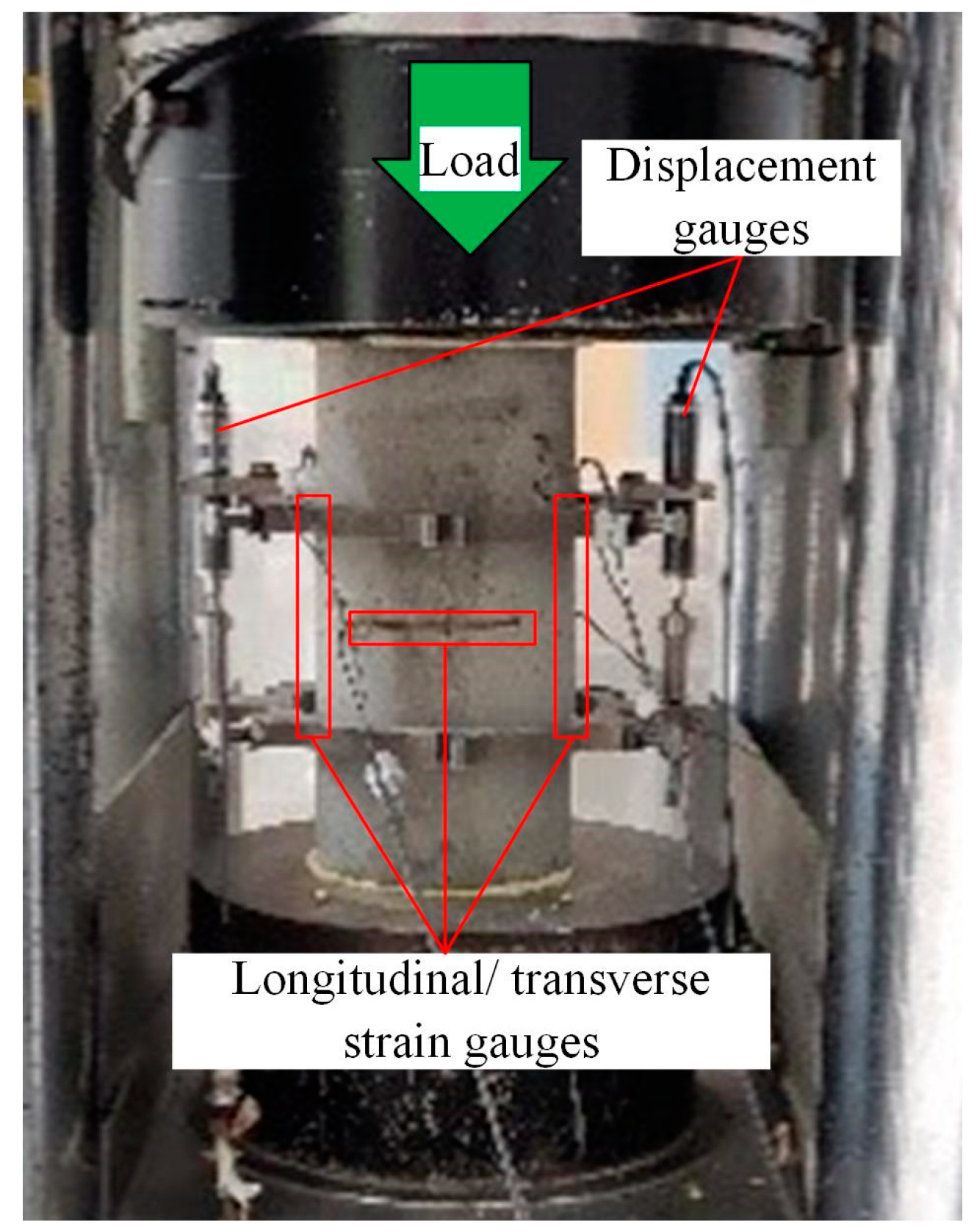
The variables included total fiber contents at 0.2%, 0.4%, 0.6%, and 0.8%, with steel and glass fibers mixed in ratios of 0:4, 1:3, 2:2, 3:1, and 4:0. These fiber contents/ratios have worked well to enhance the fracture performance of rubberized concrete [50]. Water–cement ratios were set at 0.39 to ensure proper workability and mechanical strength. Rubber particles replaced 5% of the fine aggregates to achieve a balance between mechanical strengths and sustainability. A total of 22 mix formulations were designed, including 2 control groups without fibers or rubber particles, as shown in Table 1. SF represents steel fiber, GF represents glass fiber, and R represents rubber particles. The number immediately following the abbreviations indicates the volume percentage (%). In this study, SF and GF replaced equal volumes of concrete, R replaced an equal volume of sand, and the superplasticizer (SP) replaced an equal mass of cement and water.
The ingredients were mixed in three steps, as follows: (1) mixing cement, sand, rubber particles, and fibers in the mixer bowl for 1 min; (2) adding 70% of the proportioned water and superplasticizer into the mixer bowl, stirring for another 1 min; and (3) adding the coarse aggregates and the remaining 30% of the proportioned water to the mixer, stirring for another 3 min. Then, the fresh paste was cast into cylindrical molds that were 150 mm in diameter and 300 mm in height. The specimens were placed under 20 °C ± 2 °C and humidity > 50 RH% for 24 h and then demolded and cured at 20 °C ± 2 °C and humidity > 95 RH% for 28 days.

2.3. Methods

Slump tests were conducted on the freshly mixed paste according to Chinese standard GB/T 50080-2016 [52]. After curing, the specimens were subject to compression tests, as shown in Figure 2. Two 100 mm strain gauges were attached longitudinally, and two 80 mm strain gauges were attached transversely to the center of the specimen surfaces. The strain gauges with the same size were placed in positions opposite to each other to capture strain changes and to detect any eccentric loading. The specimen ends were plastered to form level surfaces before testing. Two hoops were attached at the quarters of the specimens to prevent premature strain gauge damages caused by cracking/spalling of the specimens. Displacement gauges were fixed on the hoops to record changes in specimen displacement during the axial compression.
Compression tests of the specimens were carried out on a Matest tester machine with a loading capacity of 4000 kN. The specimens were compressed at a loading rate of 0.18 mm/min as per ASTM C469/C469M [53]. The test data (force, strain, and displacement) were collected at 1 Hz. During the tests, the crack generation time and the crack pattern changes in the specimens were also recorded.
Calculation methods of the compressive strength, elastic modulus, Poisson’s ratio, peak strain, and compressive toughness of the specimens are as follows. The compressive strength fc was obtained by dividing the peak load value by the specimen cross-sectional area. The modulus of elasticity E is calculated according to Equation (1), as follows:
E = σ 1 σ 2 ε 1 0.000050
where σ1 denotes the stress corresponding to 40% of the peak load in the rising section of the stress–strain curve, σ2 is the stress corresponding to 0.000050 of the longitudinal strain, and ε1 denotes the longitudinal strain corresponding to 40% of the maximum load in the rising section of the stress–strain curve.
Poisson’s ratio μ was calculated according to Equation (2) as follows:
μ = ε t 1 ε t 2 ε 1 0.000050
where εt1 and ε1 denote the transverse and longitudinal strains corresponding to 40% of the maximum load in the ascending section of the stress–strain curve, respectively; and εt2 denotes the transverse strain corresponding to 0.000050 longitudinal strain.
The peak strain is the longitudinal strain corresponding to its maximum compressive strength. Compressive toughness T is calculated according to Equation (3) as follows:
T = 0 ε 3 σ d ε
where σ is the longitudinal compressive stress, ε is the longitudinal strain, and ε3 is the longitudinal strain corresponding to an 80% decrease in compressive strength after the peak point of stress in the stress–strain curve.
To simulate the stress–strain relationship, a widely used constitutive model proposed by Guo [54] was adopted, which was also incorporated into Chinese standard GB 50010-2002 [55]. The schematic model is displayed in Figure 3 and the model is described in Equation (4), as follows:
y = A x + 3 2 A x 2 + A 2 x 3 ,   ( 0 x 1 ) x B x 1 2 + x   ,   ( x 1 )
where y is the ratio of the current stress to the peak stress (σ/fc), and x is the ratio of the current strain to the peak strain (ε/εc). A is the ratio of the initial tangential elastic modulus to the peak secant elastic modulus in the first segment, and B is the plasticity index of the shape-fitting parameter in the second segment.

3. Results and Discussion

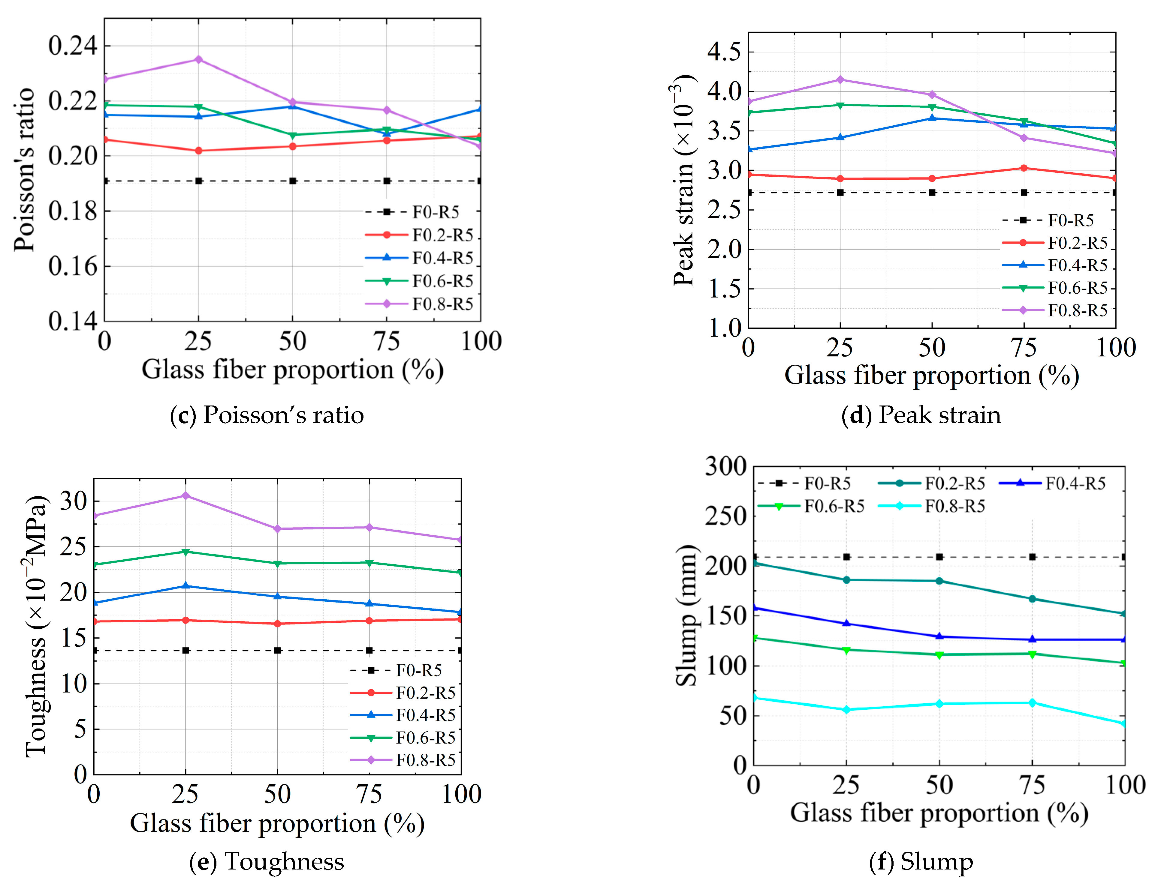
3.1. Slump Test Results
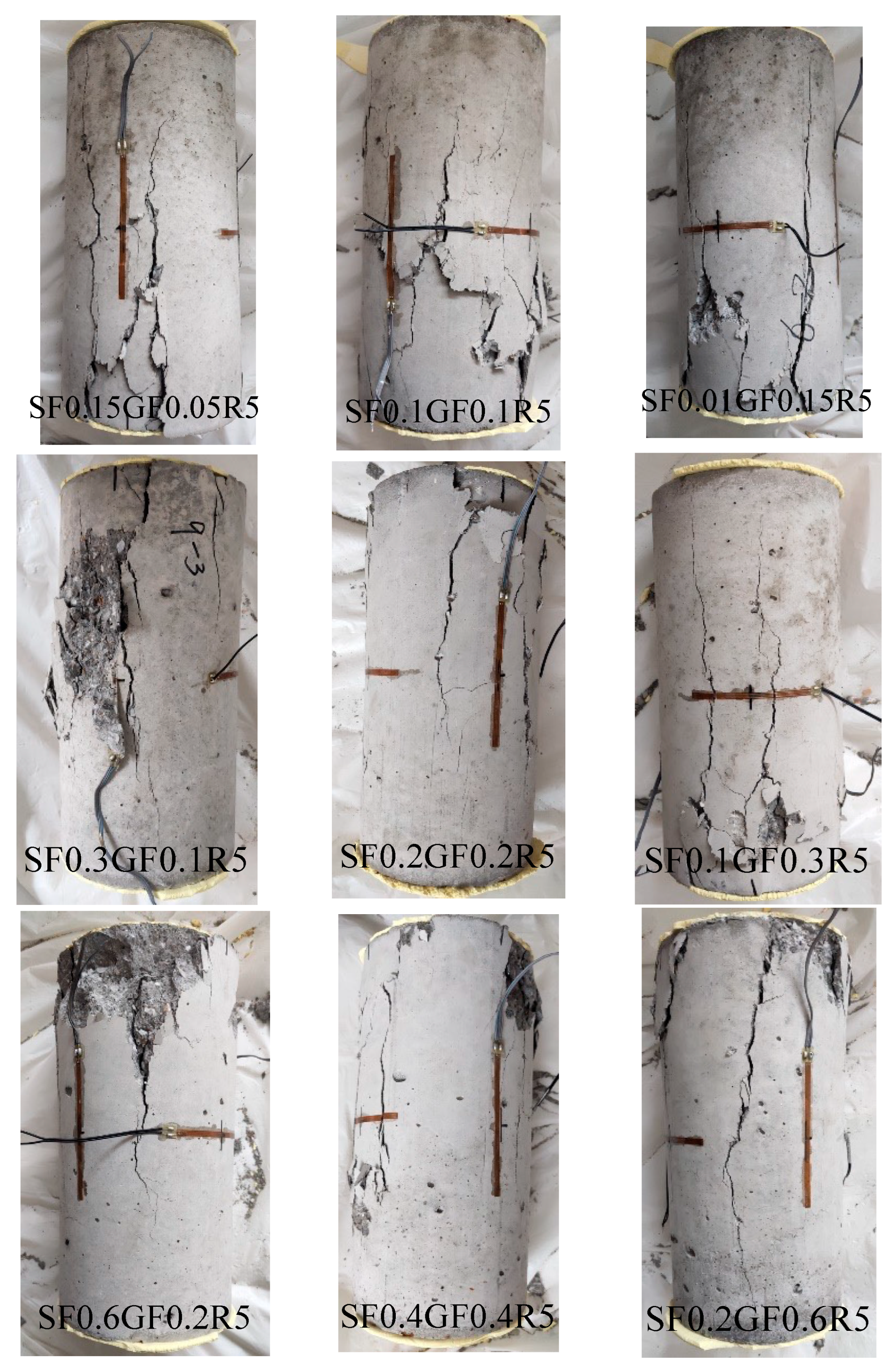
Figure 4f displays the slump test results. The plain concrete showed a slump of 198 mm. For concrete with 5% rubber particles, the slump became 209 mm. The increase in slump value is attributed to the air entrainment by the rubber particles, acting as an air entrainer [56]. The entrained air reduces the friction between particles/aggregates and the cement paste, resulting in a slight increase in slump. With the incorporation of steel/glass fibers, the slump value of the rubberized concrete gradually decreases with the fiber content, as the fibers introduce additional surface areas to be wetted/coated, leading to decreased workability. Notably, the slump of the rubberized concrete with hybrid fibers decreased with an increase in the proportion of glass fibers at the same total fiber content. This is likely because the hydrophilic glass fibers [57], being finer and more numerous than the steel fibers at the same fiber content, absorb more moisture, thus reducing flowability.

3.2. Failure Mode

Failure modes after the axial compressive tests are shown in Figure 5. SF0GF0R0 represents the plain concrete and SF0GF0R5 denotes the rubberized concrete. The plain concrete specimens were axially deformed but did not crack when loading reached its peak value. After that, cracks began to occur in the middle of the specimen with an increase in axial deformation. As the cracks developed and gradually extended to both ends, the specimen was quickly broken. After failure, the crack widths and numbers were relatively large, and the specimens showed obvious brittleness. The rubberized specimens behaved similarly to the plain concrete before cracking. However, the crack generation occurred before that of the plain concrete, as the rubber particles reduced the concrete strength and cracking occurred earlier. There were fewer cracks after failure in the rubberized concrete, probably because the highly elastic rubber particles enhanced the concrete toughness (by 11.7%, as shown in Table 2), allowing for greater deformation before compression failure. In other words, a single crack could deform more and absorb more energy; therefore, fewer cracks were generated to dissipate the input energy.
For the rubberized concrete incorporated with a single type of fiber, more cracks appeared in the specimens, which cracked slowly and showed ductile failures. In general, the cracking time of the glass fiber-reinforced rubberized concrete was later than that of the steel fiber-reinforced concrete, and the cracking started with small cracks at both ends and extended to large cracks in the middle of the specimens. When the small cracks contacted the middle large cracks, the specimen failed after a short period.
In the rubberized concrete with hybrid fibers, specimens exhibited delayed cracking with increasing glass fiber proportions. Cracks initiated at the middle of the specimens; then, small diagonal cracks appeared at both ends and gradually extended to the middle until failure occurred. The failed specimens are shown in Figure 6. In general, the failure mode of the rubberized concrete with fibers shifted from shear failure to tensile failure [14].
While rubber particles softened the concrete matrix and reduced the matrix cracking strength, fiber incorporation toughened the matrix, slowed cracking, and ultimately delayed specimen failure. The addition of glass fibers may have delayed cracking in the specimens compared to the addition of steel fibers. Specimens with hybrid fibers showed increasing delays in cracking with higher proportions of glass fibers. This is because the relatively flexible glass fibers enhanced specimen strain capacity (Figure 4e) and inhibited microcrack development into larger cracks [38]. Slowed cracking can enhance the durability of rubberized concrete, particularly when steel rebars are incorporated.

3.3. Compression Test Results

The compressive strength, elastic modulus, Poisson’s ratio, peak strain, and compressive toughness were determined using the methods outlined in Section 2.3 and are tabulated in Table 2. The values in parentheses represent changes relative to those of rubberized concrete without the incorporation of fibers. Detailed discussions of the results are provided in subsequent sections.

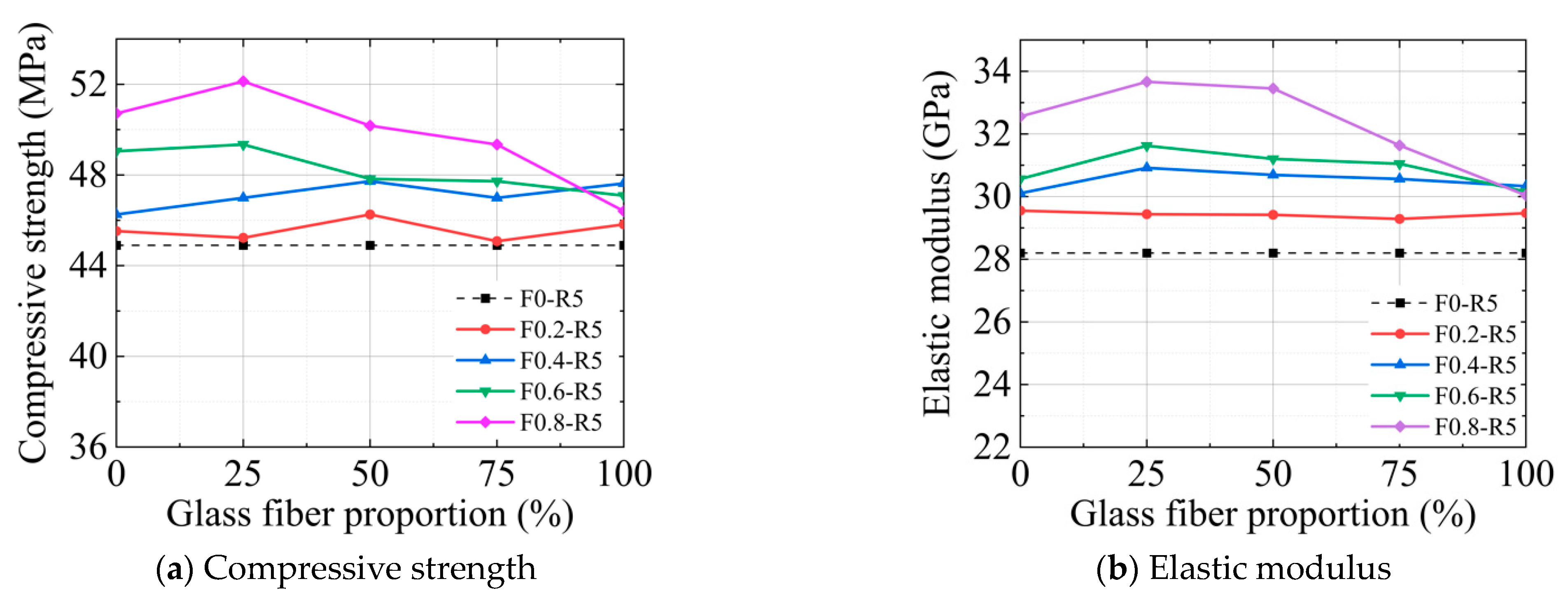
3.4. Compressive Strength

The changes in the rubberized concrete compressive strength with the hybrid ratio of the two fibers are shown in Figure 4a. While the rubber particles led to a 5% decrease in the compressive strength (Table 2), fiber incorporation enhanced the compressive strength of the rubberized concrete. Moreover, the fiber-reinforced rubberized concrete showed even higher compressive strengths than the plain concrete at some dosages (Table 2). In general, the incorporation of the steel fiber alone consistently enhanced the compressive strength of the rubberized concrete at dosages from 0.2% to 0.8%. The addition of only glass fibers showed fluctuating strength improvements of 2.0%, 6.1%, 4.9%, and 3.4% in relation to those of the plain concrete at dosages 0.2%, 0.4%, 0.6%, and 0.8%, respectively. The results indicate that although the glass fibers improved the compressive strength of the rubberized concrete, dosages higher than 0.4% adversely affected the strength improvement.
Above a fiber dosage of 0.2%, rubberized concrete with specific hybrid fibers exhibited higher compressive strengths compared to those with either steel or glass fibers alone. At a dosage of 0.8% (SF0.6% + GF0.2%), where the ratio of steel fibers to glass fibers is 3:1, the rubberized concrete showed the greatest improvement in compressive strength. The results indicate a positive synergy between the steel and glass fibers in enhancing the compressive strength of rubberized concrete.

3.5. Elastic Modulus

Incorporating rubber particles decreased the elastic modulus of the specimens by 2.8% (Table 2), softening the concrete. However, with steel fiber incorporation, the elastic modulus of the rubberized concrete increased by 4.8%, 6.8%, 8.4%, and 15.5% at dosages of 0.2%, 0.4%, 0.6%, and 0.8%, respectively. Regarding the addition of the glass fibers, the elastic modulus of the rubberized concrete increased by 4.5%, 7.6%, 7.0%, and 6.6% at dosages of 0.2%, 0.4%, 0.6%, and 0.8%, respectively. The improvement in elastic modulus from the glass fibers began to diminish when the fiber dosage exceeded 0.4%. Overall, incorporating steel/glass fibers not only compensated for the losses in elastic modulus due to the rubber particles but also caused the concrete to be stiffer than that without rubber particles.
The change in the elastic modulus of the specimens related to the hybrid ratio of the two fibers is depicted in Figure 4b. When the hybrid fiber dosage reached 0.8% (SF0.6% + GF0.2%), the elastic modulus of the rubberized concrete reached its maximum, which was 1.2 times that of the plain rubberized concrete. Therefore, while incorporating a single type of steel/glass fiber improved the elastic modulus of rubberized concrete, utilizing a hybrid combination of the two fibers could further enhance it.

3.6. Poisson’s Ratio

The changes in the Poisson’s ratio of the specimens concerning the hybrid ratio of the two fibers is illustrated in Figure 4c. The addition of rubber particles reduced the Poisson’s ratio of the concrete from 0.191 to 0.178 (Table 2). Incorporating steel or glass fibers increased the Poisson’s ratios to 0.223 and 0.217, respectively. Utilizing a hybrid combination of the two fibers resulted in a Poisson’s ratio of 0.235 for the rubberized concrete. Since higher Poisson’s ratios can indicate that the material is harder to break or fracture [58], enhancements in the Poisson’s ratio are beneficial for rubberized concrete. Generally, when steel fiber dosages are relatively high (e.g., 0.6% and 0.8%), small glass fiber dosages were sufficient to further enhance Poisson’s ratios. Conversely, when steel fiber dosages were relatively low (e.g., 0.2% and 0.4%), larger glass fiber dosages were required to synergize with the steel fiber.

3.7. Peak Strain

The peak strain changes concerning the hybrid ratio of the two fibers are shown in Figure 4d. After adding rubber particles, the peak strain of the specimens decreased by 6.7% (Table 2) but increased with the fiber incorporation. With the steel fiber incorporation, the peak strain of the rubberized concrete increased by 16.1%, 28.7%, 46.9%, and 52.8% at dosages of 0.2%, 0.4%, 0.6% and 0.8%, respectively. With the addition of the glass fibers, the peak strain increased by 14.2%, 39.0%, 31.5% and 26.8% at dosages of 0.2%, 0.4%, 0.6% and 0.8%, respectively. The results show that the peak strain of the rubberized concrete consistently increased with the steel fiber dosages, while the peak strain first increased but then decreased with the glass fiber dosages. With a hybrid fiber dosage of 0.8% (SF0.6% + GF0.2%), the peak strain of the rubberized concrete increased to 63.4%, surpassing the peak strain achieved by incorporating a single type of fiber.

3.8. Compressive Toughness

Figure 4e illustrates the changes in compressive toughness of the specimens with the hybrid ratios of the two fibers. While the addition of rubber particles slightly improved the compressive toughness by 12.1%, the incorporation of fibers substantially enhanced it. Rubber particles enhance compressive toughness by absorbing energy during compression, thus reducing crack propagation (Figure 5). In general, the compressive toughness of the rubberized concrete increased with the total fiber content. Specimens with only the steel fiber showed an 87.2% improvement at a fiber content of 0.8%. When only glass fibers were incorporated, there was a similar trend, but the improvement was slightly lower, at 69.8%, with a fiber content of 0.8%. With hybrid fibers, the compressive toughness remained nearly unchanged at a low dosage (0.2%). When the total fiber content increased, the compressive toughness at 0.8% (SF0.6% + GF0.2%) was improved by 101.7%, exceeding that achieved by either single type of fiber.

3.9. Discussion on the Effects of the Fibers on Compressive Performances

The addition of steel fibers alone moderately improved the compressive strength and elastic modulus of the rubberized concrete but significantly enhanced the peak strain and compressive toughness. This is because moderate amounts (0.4–0.8% in this study) of the steel fibers could be evenly distributed and effectively control the development and propagation of macrocracks [29].
Incorporating glass fibers alone enhanced the compressive strength, elastic modulus, Poisson’s ratio, peak strain, and compressive toughness of the rubberized concrete. However, when the glass fiber content surpassed specific thresholds (0.4% in this study), all the aforementioned parameters except compressive toughness began to decrease. This phenomenon is attributed to the dispersion of glass fibers. At suitable fiber content levels (below 0.6% in this study), glass fibers can be effectively dispersed to manage the development and propagation of microcracks [44] during specimen loading. However, excessive fiber content leads to poorer glass fiber dispersion [59], affecting concrete flowability and potentially causing internal defects.
Incorporating hybrid fibers (dosages greater than 0.2%) resulted in the compressive strength, elastic modulus, Poisson’s ratio, peak strain, and compressive toughness of the rubberized concrete initially increasing and then decreasing with the proportion of glass fibers. The enhancements are attributed to the positive synergy between the steel fibers and glass fibers in the rubberized concrete. Glass fibers, being finer and more flexible than steel fibers, could disperse well in locations where steel fibers are scarce, providing additional micro-crack bridging. However, when the glass fiber proportions increased, the fiber dispersion began to deteriorate, and reduced enhancements ensued.
The test results indicate that an optimal dosage range for steel fiber is between 0.6% and 0.8%; for glass fiber, it is between 0.2% and 0.4%. Dosages below these ranges minimally impacted compressive performance, while excessive dosages reduced concrete flowability. Reduced concrete flowability results in inadequate fiber dispersion and the formation of porosity/defects, subsequently decreasing compressive strength. In general, when the steel fiber dosages were relatively high (e.g., 0.6% and 0.8%), only small dosages of the glass fiber were required to further improve the compressive strength; when the steel fiber dosages were relatively low (e.g., 0.2% and 0.4%), larger dosages of the glass fiber were required to synergize with the steel fiber.
This study shows that a hybrid fiber content of 0.8% (SF0.6% + GF0.2%) could enhance compressive strength and elastic modulus by 16.1% and 19.4%, respectively, compared to plain rubberized concrete. This improvement is slightly lower than that reported in [37], where a hybrid fiber content of 1.0% (SF0.9% + PP0.1%) enhanced the compressive strength of rubberized concrete with 20% fine aggregates replaced by crumb rubber by 28%. The higher enhancement reported in [37] is likely due to the use of a higher steel fiber dosage and higher rubber content. Another study [43] showed much weaker enhancements; a hybrid fiber content of 0.25% (20% SF and 80% PET) marginally improved the compressive strength and elastic modulus of a rubberized concrete with 10% sand volume replaced by rubber, while a higher hybrid fiber content of 0.35% (50% SF and 50% PET) even reduced these properties, which was attributed to the poor adhesion of PET to cement pastes.
It appears that the optimal dosages for the steel/glass fibers used in this study were also applicable in enhancing the flexural and fracture properties of the rubberized concrete [48], indicating that similar fiber synergy mechanisms govern both the compressive and flexural performances of this material.

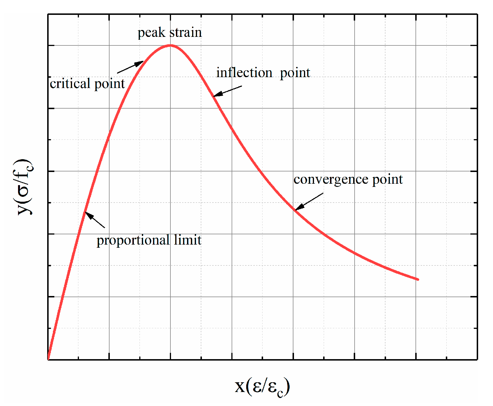
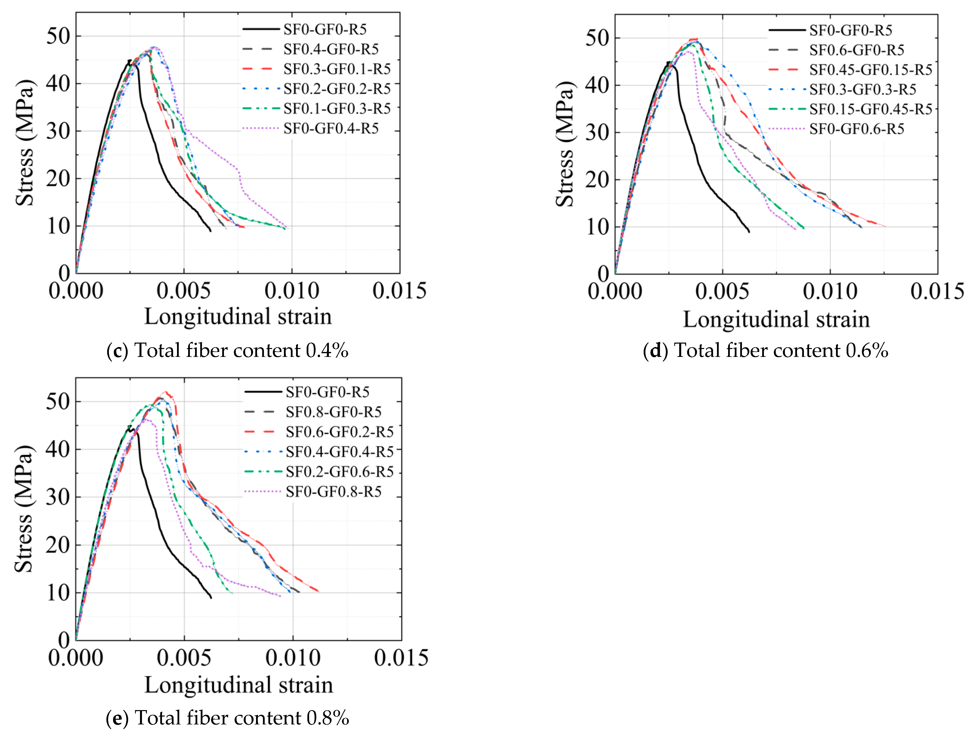
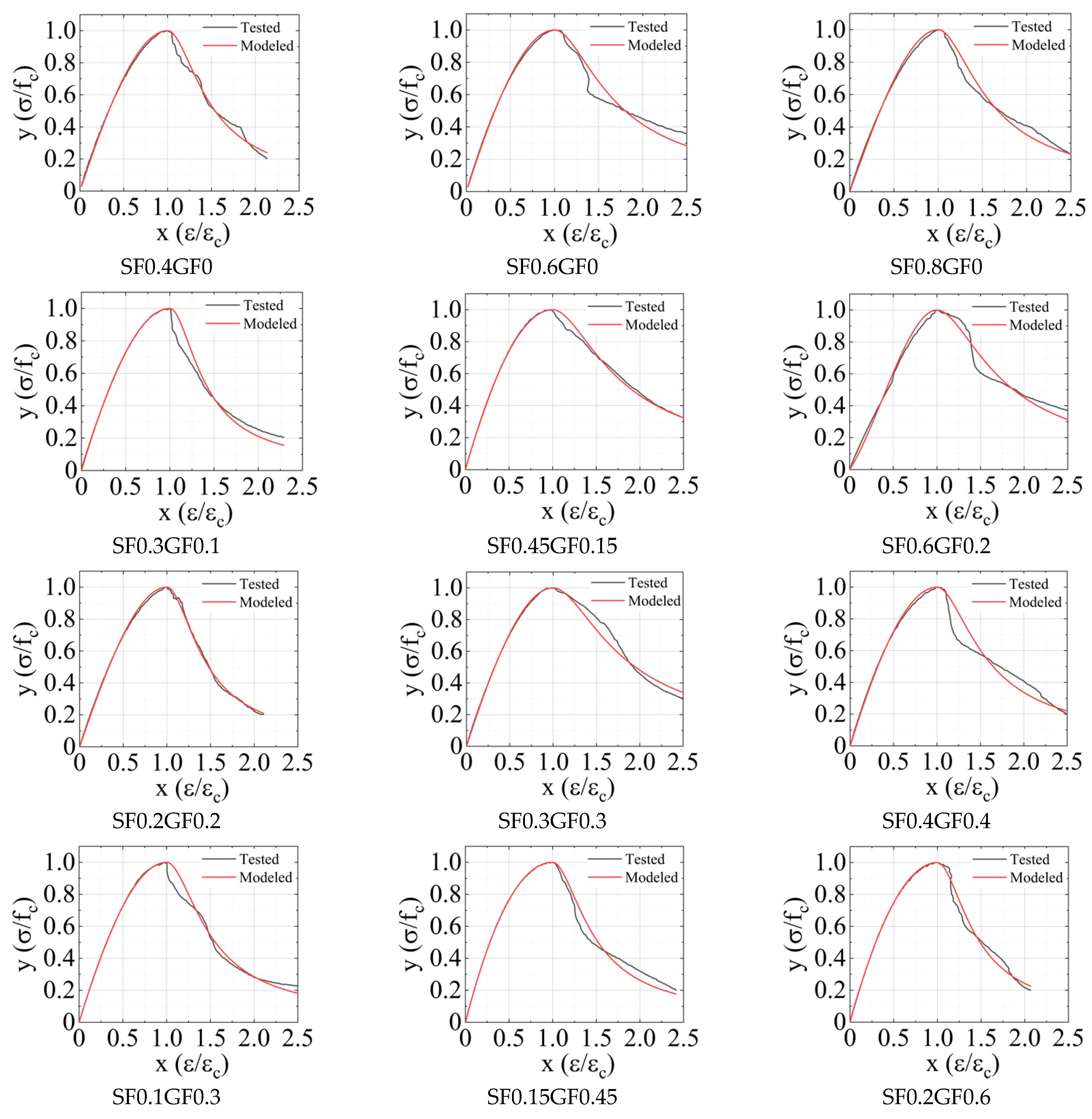
3.10. Stress–Strain Curve and Constitutive Model Simulation

The stress–strain curves of the specimens are presented in Figure 7. In general, each curve comprises three segments, as follows: a linear ascending section; a nonlinear ascending segment; and a descending segment after reaching the peak. The linear ascending section primarily extends from the beginning of the load to a proportional limit (at about 40% of the peak stress). The nonlinear ascending section primarily extends from the proportional limit point to the peak stress point. The descending section occurs between the peak stress point and the complete failure point of the specimen. With the addition of rubber particles, the stress–strain curve ascended/descended more gently than that of the plain concrete, suggesting that the rubber particles improved ductility. However, the incorporation of rubber particles also reduced the peak stress (compressive strength) (Figure 7a). As can be seen in Figure 7b to 8e, the stress–strain curves of the specimens with the glass fibers were mostly below those of the specimens with the steel fibers, indicating that the steel fibers improved the compressive performance more than the glass fibers. With the hybrid fibers incorporated, the descending sections of a few stress–strain curves lie above those of the specimens with a single type of fiber, showing that certain hybrid fibers outperform the single fibers. At a total fiber content of 0.2%, the peak stresses of the specimens were similar to those of the specimens with a single type of fiber, indicating minimal synergistic effects. When the total fiber content was 0.6% or 0.8%, the peak stresses of the specimens with hybrid fibers showed obvious improvements compared to those of the specimens with a single type of fiber.
Due to the brittleness of plain rubberized concrete and the limited improvements observed with a fiber content of 0.2%, data from the specimens with a fiber content above 0.2% were used to construct the constitutive model. The specimens were divided into five groups: GF-0%, GF-25%, GF-50%, GF-75%, and GF-100%, based on the glass fiber proportions in the hybrid fibers. The values of A and B, which are the parameters for the model developed by Guo [54], are shown in Table 3.
The simulated stress–strain relationships, along with the tested stress–strain curves, are presented in Figure 8. Visual inspections show that the simulated data closely match the tested data in the ascending sections and could largely capture the decline trends in the descending sections. These results can aid in establishing a unified constitutive model for predicting the compressive behavior of rubberized concrete with hybrid fibers in the future, following thorough validation against independent datasets or field observations under ambient or elevated temperatures [60,61,62,63,64,65,66].

4. Conclusions

This study explored the effects of steel/glass fibers on the compressive behavior of rubberized concrete. Twenty-two concrete formulations were designed, and axial compressive tests were carried out. The following conclusions are drawn:
Incorporating hybrid fibers outperformed the uses of single types of fibers in enhancing the compressive performance of rubberized concrete due to positive fiber synergy. A hybrid fiber content of 0.8% (SF0.6% + GF0.2%) showed the maximum enhancements.
The recommended steel fiber contents are between 0.6% and 0.8% and glass fiber contents should be between 0.2% and 0.4% to achieve the desired enhancements. Fiber contents outside these ranges either contributed minimally to compressive performance or reduced workability.
A constitutive model was adopted for rubberized concrete incorporating hybrid fibers using the experimental data. The model fit the test data well in the ascending sections and could largely capture the decline trends in the descending sections.
While this study varied the total fiber content and glass fiber proportions, other parameters, such as rubber particle sizes, mix design variations, and environmental conditions, may affect the conclusions. Further research is needed to address these influences.

Author Contributions

Conceptualization, H.L. and L.L.; methodology, P.F.; software, Z.L.; validation, W.Z. and Z.L.; formal analysis, X.L.; investigation, H.L. and D.W.; resources, D.W.; data curation, P.F.; writing—original draft preparation, H.L.; writing—review and editing, W.Z.; visualization, X.L.; supervision, F.L.; project administration, L.L.; funding acquisition, L.L. and F.L. All authors have read and agreed to the published version of the manuscript.

Funding

This research was funded by the National Natural Science Foundation of China, grant numbers 12072080 and 12032009.

Data Availability Statement

Data are contained within the article.

Acknowledgments

The authors gratefully acknowledge the financial support provided by the National Natural Science Foundation of China under Grant No. 12072080 and Grant No. 12032009.

Conflicts of Interest

Author Daochu Wang and Zao Ling were employed by the company Guangzhou Construction Engineering Co., Ltd. The remaining authors declare that the research was conducted in the absence of any commercial or financial relationships that could be construed as a potential conflict of interest.

Abbreviations

GFGlass fiber
PETPolyethylene terephthalate
PPpolypropylene
RRubber particles
SFSteel fiber
SPSuperplasticizer

References

  1. Guo, Z.; Qiu, J.; Kirichek, A.; Zhou, H.; Liu, C.; Yang, L. Recycling waste tyre polymer for production of fibre reinforced cemented tailings backfill in green mining. Sci. Total Environ. 2024, 908, 168320. [Google Scholar] [CrossRef] [PubMed]
  2. Elchalakani, M. High strength rubberized concrete containing silica fume for the construction of sustainable road side barriers. Structures 2015, 20, 20–38. [Google Scholar] [CrossRef]
  3. Longvinenko, A. Use of rubber crumbs in cement concrete. In Proceedings of the IOP Conference Series: Materials Science and Engineering, Tomsk, Russian Federation, 4–6 December 2017; IOP Publishing: Bristol, UK, 2018. [Google Scholar]
  4. Khelaifa, H.; Boudaoud, Z.; Benouis, A. Effect of adding rubber aggregates on the behaviour of compacted sand concrete. Innov. Infrastruct. Solut. 2021, 6, 143. [Google Scholar] [CrossRef]
  5. Wang, L.; Xie, X.G.; Fan, L.L. Study of Road Performance between Rub-concrete and Normal Concrete Materials. Advanced Engineering Forum. 2012, 5, 358–363. [Google Scholar] [CrossRef]
  6. Meng, X.; Yang, J.; Ding, N.; Lu, B. Identification of the potential environmental loads of waste tire treatment in China from the life cycle perspective. Resour. Conserv. Recycl. 2023, 193, 106938. [Google Scholar] [CrossRef]
  7. Hosseinzadehfard, E.; Mobaraki, B. Investigating concrete durability: The impact of natural pozzolan as a partial substitute for microsilica in concrete mixtures. Constr. Build. Mater. 2024, 419, 135491. [Google Scholar] [CrossRef]
  8. Fayed, S.; Aksoylu, C.; Ecemiş, A.S.; Madenci, E.; Özkılıç, Y.O. Tensile Behavior of Green Concrete Made of Fine/Coarse Recycled Glass and Recycled Concrete Aggregates. Buildings 2024, 14, 2969. [Google Scholar] [CrossRef]
  9. Fu, X.; Chung, D.D.L. Vibration damping admixtures for cement. Cem. Concr. Res. 1996, 26, 69–75. [Google Scholar] [CrossRef]
  10. Li, H.B.; Wang, B.; Zou, Y.Y. Experimental Study on Force-Bearing Performance of Road Concrete which Modified by Fiber and Rubber Powder. Appl. Mech. Mater. 2012, 204, 4015–4021. [Google Scholar] [CrossRef]
  11. Eltayeb, E.; Ma, X.; Zhuge, Y.; Xiao, J.; Youssf, O. Dynamic performance of rubberised concrete and its structural applications–An overview. Eng. Struct. 2021, 234, 111990. [Google Scholar] [CrossRef]
  12. Liu, H.; Wang, X.; Jiao, Y.; Sha, T. Experimental investigation of the mechanical and durability properties of crumb rubber concrete. Materials 2016, 9, 172. [Google Scholar] [CrossRef] [PubMed]
  13. Suchat, S.; Aditapsatit, P. On the Performance of Hybrid Natural Rubber Rubberized Concrete. Adv. Mater. Res. 2014, 844, 186–189. [Google Scholar] [CrossRef]
  14. Zhang, H.B. Influence of Rubber Crumb Addition to Portland Cement Concrete. Adv. Mater. Res. 2012, 391, 600–605. [Google Scholar] [CrossRef]
  15. Youssf, O.; Mills, J.E.; Benn, T.; Zhuge, Y.; Ma, X.; Roychand, R.; Gravina, R. Development of crumb rubber concrete for practical application in the residential construction sector–design and processing. Constr. Build. Mater. 2020, 260, 119813. [Google Scholar] [CrossRef]
  16. Ahmed, S.; Elshazli, M.T.; Zaghlal, M.; Alashker, Y.; Abdo, A. Improving Shear Behavior of Rubberized Concrete Beams through Sustainable Integration of Waste Tire Steel Fibers and Treated Rubber. J. Build. Eng. 2024, 96, 110649. [Google Scholar] [CrossRef]
  17. Hassanean, M.A.M.; Hussein, S.A.M.; Elsayed, M. Shear behavior of reinforced concrete beams comprising a combination of crumb rubber and rice husk ash. Eng. Struct. 2024, 319, 118862. [Google Scholar] [CrossRef]
  18. Chen, L.; Chen, X.; Liu, Z.; Lu, K.; Liu, J.; Wang, Z. Mechanical properties of macro-synthetic fiber reinforced rubber concrete under uniaxial loading. Constr. Build. Mater. 2024, 445, 137821. [Google Scholar] [CrossRef]
  19. Cao, Y.; Liu, Y.; Li, X.; Wu, Y. Axial stress strain behavior of FRP-confined rectangular rubber concrete columns with different aspect ratio. Eng. Struct. 2023, 297, 116987. [Google Scholar] [CrossRef]
  20. Khan, I.; Shahzada, K.; Bibi, T.; Ahmed, A.; Ullah, H. Seismic performance evaluation of crumb rubber concrete frame structure using shake table test. Structures 2021, 30, 41–49. [Google Scholar] [CrossRef]
  21. Alshaikh, I.M.H.; Bakar, B.H.A.; Alwesabi, E.A.H.; Zeyad, A.M.; Magbool, H.M. Finite element analysis and experimental validation of progressive collapse of reinforced rubberized concrete frame. Structures 2021, 33, 2361–2373. [Google Scholar] [CrossRef]
  22. Merwad, A.M.; El-Sisi, A.A.; Mustafa, S.A.A.; Sallam, H.E.-D.M. Lateral impact response of rubberized-fibrous concrete-filled steel tubular columns: Experiment and numerical study. Buildings 2022, 12, 1566. [Google Scholar] [CrossRef]
  23. Liu, B.; Zhang, L.; Feng, M.; Sun, H.; Chai, Y. Experimental study of rubber-concrete-filled CST composite column under axial compression. Int. J. Steel Struct. 2023, 23, 247–262. [Google Scholar] [CrossRef]
  24. Ganjian, E.; Khorami, M.; Maghsoudi, A.A. Scrap-tyre-rubber replacement for aggregate and filler in concrete. Constr. Build. Mater. 2009, 23, 1828–1836. [Google Scholar] [CrossRef]
  25. Mohammed, B.S.; Awang, A.B.; San Wong, S.; Nhavene, C.P. Properties of nano silica modified rubbercrete. J. Clean. Prod. 2016, 119, 66–75. [Google Scholar] [CrossRef]
  26. He, L.; Ma, Y.; Liu, Q.; Mu, Y. Surface modification of crumb rubber and its influence on the mechanical properties of rubber-cement concrete. Constr. Build. Mater. 2016, 120, 403–407. [Google Scholar] [CrossRef]
  27. Wongthong, P.; Nakason, C.; Pan, Q.; Rempel, G.L.; Kiatkamjornwong, S. Modification of deproteinized natural rubber via grafting polymerization with maleic anhydride. Eur. Polym. J. 2013, 49, 4035–4046. [Google Scholar] [CrossRef]
  28. Gupta, T.; Chaudhary, S.; Sharma, R.K. Assessment of mechanical and durability properties of concrete containing waste rubber tire as fine aggregate. Constr. Build. Mater. 2014, 73, 562–574. [Google Scholar] [CrossRef]
  29. He, L.; Cai, H.; Huang, Y.; Ma, Y.; Van Den Bergh, W.; Gaspar, L.; Valentin, J.; Vasiliev, Y.E.; Kowalski, K.J.; Zhang, J. Research on the properties of rubber concrete containing surface-modified rubber powders. J. Build. Eng. 2021, 35, 101991. [Google Scholar] [CrossRef]
  30. Liang, J.; Zhu, H.; Chen, L.; Han, X.; Guo, Q.; Gao, Y.; Liu, C. Rebar corrosion investigation in rubber aggregate concrete via the chloride electro-accelerated test. Materials 2019, 12, 862. [Google Scholar] [CrossRef]
  31. Pan, Z.; Liu, F.; Li, H.; Li, X.; Wang, D.; Ling, Z.; Zhu, H.; Zhu, Y. Performance evaluation of thermal insulation rubberized mortar modified by fly ash and glass fiber. Buildings 2024, 14, 221. [Google Scholar] [CrossRef]
  32. Zhen, H.; Xiong, Z.; Song, Y.; Li, L.; Qiu, Y.; Zou, X.; Chen, B.; Chen, D.; Liu, F.; Ji, Y. Early mechanical performance of glass fibre-reinforced manufactured sand concrete. J. Build. Eng. 2024, 83, 108440. [Google Scholar] [CrossRef]
  33. Li, H.; Liu, F.; Pan, Z.; Li, H.; Wu, Z.; Li, L.; Xiong, Z. Use of supplementary cementitious materials in seawater–sea sand concrete: State-of-the-art review. Constr. Build. Mater. 2024, 425, 136009. [Google Scholar] [CrossRef]
  34. Wang, J.; Dai, Q.; Si, R.; Guo, S. Mechanical, durability, and microstructural properties of macro synthetic polypropylene (PP) fiber-reinforced rubber concrete. J. Clean. Prod. 2019, 234, 1351–1364. [Google Scholar] [CrossRef]
  35. Zhu, H.; Xiong, Z.; Song, Y.; Zhou, K.; Su, Y. Effect of expansion agent and glass fiber on the dynamic splitting tensile properties of seawater–sea-sand concrete. Buildings 2024, 14, 217. [Google Scholar] [CrossRef]
  36. Alsaif, A.; Garcia, R.; Figueiredo, F.P.; Neocleous, K.; Christofe, A.; Guadagnini, M.; Pilakoutas, K. Fatigue performance of flexible steel fibre reinforced rubberised concrete pavements. Eng. Struct. 2019, 193, 170–183. [Google Scholar] [CrossRef]
  37. Alwesabi, E.A.H.; Bakar, B.H.A.; Alshaikh, I.M.H.; Zeyad, A.M.; Altheeb, A.; Alghamdi, H. Experimental investigation on fracture characteristics of plain and rubberized concrete containing hybrid steel-polypropylene fiber. Structures 2021, 33, 4421–4432. [Google Scholar] [CrossRef]
  38. Alwesabi, E.A.H.; Bakar, B.H.A.; Alshaikh, I.M.H.; Akil, H.M. Experimental investigation on mechanical properties of plain and rubberised concretes with steel–polypropylene hybrid fibre. Constr. Build. Mater. 2020, 233, 117194. [Google Scholar] [CrossRef]
  39. Alwesabi, E.A.; Bakar, B.H.A.; Alshaikh, I.M.H.; Akil, H.M. Impact resistance of plain and rubberized concrete containing steel and polypropylene hybrid fiber. Mater. Today Commun. 2020, 25, 101640. [Google Scholar] [CrossRef]
  40. Khan, M.; Cao, M.; Xie, C.; Ali, M. Effectiveness of hybrid steel-basalt fiber reinforced concrete under compression. Case Stud. Constr. Mater. 2022, 16, e00941. [Google Scholar] [CrossRef]
  41. Su, Q.; Xu, J.-M.; Wang, Y.-D. Mechanical properties of hybrid fiber reinforced rubber concrete. Materials 2021, 14, 6028. [Google Scholar] [CrossRef]
  42. Huang, J.K.; Jiang, P.W.; Qian, Y.D.; Cheng, P.; Lou, R.; Luo, X. Research on mechanical property and impact performance of composite rubber hybrid fiber concrete. Arab. J. Sci. Eng. 2023, 48, 4339–4355. [Google Scholar] [CrossRef]
  43. Qadir, I.M.A.; Noaman, A.T. Effect of combination between hybrid fibers and rubber aggregate on rheological and mechanical properties of self-compacting concrete. Constr. Build. Mater. 2024, 414, 135038. [Google Scholar] [CrossRef]
  44. Yuan, Z.; Jia, Y. Mechanical properties and microstructure of glass fiber and polypropylene fiber reinforced concrete: An experimental study. Constr. Build. Mater. 2021, 266, 121048. [Google Scholar] [CrossRef]
  45. Kizilkanat, A.B.; Kabay, N.; Akyüncü, V.; Chowdhury, S.; Akça, A.H. Mechanical properties and fracture behavior of basalt and glass fiber reinforced concrete: An experimental study. Constr. Build. Mater. 2015, 100, 218–224. [Google Scholar] [CrossRef]
  46. Ahmad, J.; González-Lezcano, R.A.; Majdi, A.; Ben Kahla, N.; Deifalla, A.F.; El-Shorbagy, M.A. Glass fibers reinforced concrete: Overview on mechanical, durability and microstructure analysis. Materials 2022, 15, 5111. [Google Scholar] [CrossRef] [PubMed]
  47. Blazy, J.; Blazy, R. Polypropylene fiber reinforced concrete and its application in creating architectural forms of public spaces. Case Stud. Constr. Mater. 2021, 14, e00549. [Google Scholar] [CrossRef]
  48. Rodrigues, A.; Figueiredo, L.; Diogo, H.; Bordado, J. Mechanical behavior of PET fibers and textiles for Stent-Grafts using video extensometry and image analysis. Sci. Technol. Mater. 2018, 30, 23–33. [Google Scholar] [CrossRef]
  49. Wu, H.; Qin, X.; Huang, X.; Kaewunruen, S. Engineering, mechanical and dynamic properties of basalt fiber reinforced concrete. Materials 2023, 16, 623. [Google Scholar] [CrossRef]
  50. Xiong, Z.; Li, H.; Pan, Z.; Li, X.; Lu, L.; He, M.; Li, H.; Liu, F.; Feng, P.; Li, L. Fracture properties and mechanisms of steel fiber and glass fiber reinforced rubberized concrete. J. Build. Eng. 2024, 86, 108866. [Google Scholar] [CrossRef]
  51. Li, X.; Pan, Z.; Zhen, H.; Luo, W.; Chen, Z.; Li, H.; Wu, Z.; Liu, F.; Li, L. Combined Effects of Steel and Glass Fibres on the Fracture Performance of Recycled Rubber Concrete. Buildings 2024, 14, 864. [Google Scholar] [CrossRef]
  52. GB/T 50080-2016; Standard for Test Method of Performance on Ordinary Fresh Concrete. Ministry of Housing and Urban-Rural Development: Beijing, China, 2016.
  53. C469/C469M-22; A Standard Test Method for Static Modulus of Elasticity and Poisson’s Ratio of Concrete in Compression. ASTM International: West Conshohocken, PA, USA, 2022.
  54. Guo, Z. Strength and Stress-Strain Model of Concrete: Theory and Applications; China Architecture and Building Press: Beijing, China, 2004. [Google Scholar]
  55. Ouyang, X.; Wu, Z.; Shan, B.; Chen, Q.; Shi, C. A critical review on compressive behavior and empirical constitutive models of concrete. Constr. Build. Mater. 2022, 323, 126572. [Google Scholar] [CrossRef]
  56. Richardson, A.; Coventry, K.; Edmondson, V.; Dias, E. Crumb rubber used in concrete to provide freeze–thaw protection (optimal particle size). J. Clean. Prod. 2016, 112, 599–606. [Google Scholar] [CrossRef]
  57. Liu, W.; Zhu, Y.; Qian, C.; Dai, H.; Fu, Y.; Dong, Y. Interfacial modification between glass fiber and polypropylene using a novel waterborne amphiphilic sizing agent. Compos. Part B Eng. 2022, 241, 110029. [Google Scholar] [CrossRef]
  58. Belyadi, H.; Fathi, E.; Belyadi, F. Hydraulic Fracturing in Unconventional Reservoirs: Theories, Operations, and Economic Analysis; Gulf Professional Publishing: Oxford, UK, 2019. [Google Scholar]
  59. Paktiawal, A.; Alam, M. Alkali-resistant glass fiber high strength concrete and its durability parameters. Mater. Today Proc. 2021, 47, 4758–4766. [Google Scholar] [CrossRef]
  60. Bengar, H.A.; Shahmansouri, A.A.; Sabet, N.A.Z.; Kabirifar, K.; Tam, V.W.Y. Impact of elevated temperatures on the structural performance of recycled rubber concrete: Experimental and mathematical modeling. Constr. Build. Mater. 2020, 255, 119374. [Google Scholar] [CrossRef]
  61. Nematzadeh, M.; Shahmansouri, A.A.; Zabihi, R. Innovative models for predicting post-fire bond behavior of steel rebar embedded in steel fiber reinforced rubberized concrete using soft computing methods. Structures 2021, 31, 1141–1162. [Google Scholar] [CrossRef]
  62. Bengar, H.A.; Shahmansouri, A.A. Post-fire behavior of unconfined and steel tube confined rubberized concrete under axial compression. Structures 2021, 32, 731–745. [Google Scholar] [CrossRef]
  63. Mousavimehr, M.; Nematzadeh, M. Predicting post-fire behavior of crumb rubber aggregate concrete. Constr. Build. Mater. 2019, 229, 116834. [Google Scholar] [CrossRef]
  64. Nematzadeh, M.; Karimi, A.; Fallah-Valukolaee, S. Compressive performance of steel fiber-reinforced rubberized concrete core detached from heated CFST. Constr. Build. Mater. 2020, 239, 117832. [Google Scholar] [CrossRef]
  65. Mousavimehr, M.; Nematzadeh, M. Post-heating flexural behavior and durability of hybrid PET–Rubber aggregate concrete. Constr. Build. Mater. 2020, 265, 120359. [Google Scholar] [CrossRef]
  66. Nematzadeh, M.; Mousavimehr, M. Residual compressive stress–strain relationship for hybrid recycled PET–crumb rubber aggregate concrete after exposure to elevated temperatures. J. Mater. Civ. Eng. 2019, 31, 04019136. [Google Scholar] [CrossRef]
Figure 1. Grading of the aggregates.
Buildings 14 03474 g001
Figure 2. Loading setup of the axial compression tests.
Buildings 14 03474 g002
Figure 3. Schematic model of stress–strain relationship.
Buildings 14 03474 g003
Figure 4. Compressive properties and slump in relation to the hybrid ratio of the two fibers (F: fiber, and R: rubber particles).
Buildings 14 03474 g004aBuildings 14 03474 g004b
Figure 5. Failure modes of the concrete without (left)/with (right) rubber particles (SF: steel fiber, GF: glass fiber, and R: rubber particles).
Buildings 14 03474 g005
Figure 6. Failure modes of the rubberized concrete specimens with hybrid fibers (SF: steel fiber, GF: glass fiber, and R: rubber particles).
Buildings 14 03474 g006
Figure 7. Stress–strain curves (SF: steel fiber, GF: glass fiber, and R: rubber particles).
Buildings 14 03474 g007aBuildings 14 03474 g007b
Figure 8. Experimental and modeled stress–strain curves (SF: steel fiber, GF: glass fiber, and R: rubber particles).
Buildings 14 03474 g008aBuildings 14 03474 g008b
Table 1. Mix formulations (in kg/m3).
Mix NameCementSPWaterSFGFRSandGravel
SF0GF0R0560.02.8220.20.00 (0%)0.00 (0%)0.00 (0%)791.9844.73
SF0GF0R5560.02.8220.20.00 (0%)0.00 (0%)14.82 (5%)752.3844.73
SF0.2GF0R5560.02.8220.214.87 (0.2%)0.00 (0%)14.77 (5%)749.8841.92
SF0.15GF0.05R5560.02.8220.211.15 (0.15%)1.34 (0.05%)14.77 (5%)749.8841.92
SF0.1GF0.1R5560.02.8220.27.44 (0.1%)2.68 (0.1%)14.77 (5%)749.8841.92
SF0.05GF0.15R5560.02.8220.23.72 (0.05%)4.02 (0.15%)14.77 (5%)749.8841.92
SF0GF0.2R5560.02.8220.20.00 (0%)5.36 (0.2%)14.77 (5%)749.8841.92
SF0.4GF0R5560.02.8220.229.74 (0.4%)0.00 (0%)14.72 (5%)747.3839.10
SF0.3GF0.1R5560.02.8220.222.31 (0.3%)2.68 (0.1%)14.72 (5%)747.3839.10
SF0.2GF0.2R5560.02.8220.214.87 (0.2%)5.36 (0.2%)14.72 (5%)747.3839.10
SF0.1GF0.3R5560.02.8220.27.44 (0.1%)8.04 (0.3%)14.72 (5%)747.3839.10
SF0GF0.4R5560.02.8220.20.00 (0%)10.7 (0.4%)14.72 (5%)747.3839.10
SF0.6GF0R5560.02.8220.244.62 (0.6%)0.00 (0%)14.67 (5%)744.8836.28
SF0.45GF0.15R5560.02.8220.233.46 (0.45%)4.02 (0.15%)14.67 (5%)744.8836.28
SF0.3GF0.3R5560.02.8220.222.31 (0.3%)8.04 (0.3%)14.67 (5%)744.8836.28
SF0.15GF0.45R5560.02.8220.211.15 (0.15%)12.1 (0.45%)14.67 (5%)744.8836.28
SF0GF0.6R5560.02.8220.20.00 (0%)16.1 (0.6%)14.67 (5%)744.8836.28
SF0.8GF0R5560.02.8220.259.49 (0.8%)0.00 (0%)14.62 (5%)742.3833.47
SF0.6GF0.2R5560.02.8220.244.62 (0.6%)5.36 (0.2%)14.62 (5%)742.3833.47
SF0.4GF0.4R5560.02.8220.229.74 (0.4%)10.7 (0.4%)14.62 (5%)742.3833.47
SF0.2GF0.6R5560.02.8220.214.87 (0.2%)16.1 (0.6%)14.62 (5%)742.3833.47
SF0 GF0.8R5560.02.8220.20.00 (0%)21.4 (0.8%)14.62 (5%)742.3833.47
SF: steel fiber, GF: glass fiber, and R: rubber particles SP: superplasticizer.
Table 2. Compression test results (values in parentheses denote changes in percentages of the plain rubberized concrete specimens).
Mix NameCompressive Strength
(MPa)
Elastic
Modulus (GPa)
Poisson’s RatioPeak Strain
(×10−3)
Toughness
(×10−2 MPa)
SF0GF0R047.329.00.1912.7213.6
SF0GF0R544.9 (0.0%)28.2 (0.0%)0.178 (0.0%)2.54 (0.0%)15.2 (0.0%)
SF0.2GF0R545.5 (1.3%)29.6 (4.8%)0.206 (15.7%)2.95 (16.1%)16.8 (10.6%)
SF0.15GF0.05R545.2 (0.7%)29.4 (4.4%)0.202 (13.5%)2.89 (13.8%)16.9 (11.6%)
SF0.1GF0.1R545.9 (2.2%)29.4 (4.4%)0.203 (14.0%)2.90 (14.2%)16.6 (9.0%)
SF0.05GF0.15R545.1 (0.4%)29.3 (3.9%)0.206 (15.7%)3.03 (19.3%)16.9 (11.2%)
SF0GF0.2R545.8 (2.0%)29.5 (4.5%)0.207 (16.3%)2.90 (14.2%)17.0 (12.2%)
SF0.4GF0R546.3 (3.1%)30.1 (6.8%)0.215 (20.8%)3.27 (28.7%)18.8 (23.9%)
SF0.3GF0.1R547.0 (4.7%)30.9 (9.7%)0.214 (20.2%)3.42 (34.6%)20.7 (36.4%)
SF0.2GF0.2R547.7 (6.3%)30.7 (8.9%)0.218 (22.5%)3.66 (44.1%)19.5 (28.5%)
SF0.1GF0.3R547.0 (4.7%)30.6 (8.4%)0.208 (16.9%)3.58 (40.9%)18.7 (23.4%)
SF0GF0.4R547.6 (6.1%)30.3 (7.6%)0.217 (21.9%)3.53 (39.0%)17.8 (17.5%)
SF0.6GF0R549.1 (9.2%)30.6 (8.4%)0.218 (22.5%)3.73 (46.9%)23.0 (51.7%)
SF0.45GF0.15R549.8 (11.0%)31.6 (12.2%)0.218 (22.5%)3.83 (50.8%)24.5 (61.1%)
SF0.3GF0.3R549.3 (9.7%)31.2 (10.7%)0.208 (16.9%)3.81 (50.0%)23.2 (52.6%)
SF0.15GF0.45R548.4 (7.9%)31.1 (10.1%)0.210 (18.0%)3.63 (42.9%)23.3 (53.4%)
SF0GF0.6R547.1 (4.9%)30.2 (7.0%)0.206 (15.7%)3.34 (31.5%)22.2 (45.9%)
SF0.8GF0R550.7 (12.9%)32.6 (15.5%)0.223 (25.3%)3.88 (52.8%)28.4 (87.2%)
SF0.6GF0.2R552.1 (16.1%)33.7 (19.4%)0.235 (32.0%)4.15 (63.4%)30.6 (101.7%)
SF0.4GF0.4R550.2 (11.7%)33.5 (18.7%)0.220 (23.6%)3.96 (55.9%)27.0 (77.9%)
SF0.2GF0.6R549.3 (9.9%)31.6 (12.2%)0.217 (21.9%)3.41 (34.3%)27.2 (78.9%)
SF0GF0.8R546.4 (3.4%)30.0 (6.6%)0.204 (14.6%)3.22 (26.8%)25.8 (69.8%)
SF: steel fiber, GF: glass fiber, and R: rubber particles.
Table 3. Constitutive parameters of the rubberized concrete with the fibers.
GroupAbbreviationAB
GF-0%SF0.4GF01.6675.270
SF0.6GF01.7172.814
SF0.8GF01.5263.681
GF-25%SF0.3GF0.11.8367.483
SF0.45GF0.151.9302.318
SF0.6GF0.20.8702.431
GF-50%SF0.2GF0.21.6116.480
SF0.3GF0.31.7032.163
SF0.4GF0.41.7733.936
GF-75%SF0.1GF0.31.8095.016
SF0.15GF0.452.1235.607
SF0.2GF0.61.9916.248
GF-100%SF0GF0.41.6942.801
SF0GF0.62.0344.324
SF0GF0.81.5314.426
(SF: steel fiber, GF: glass fiber, and R: rubber particles).
Disclaimer/Publisher’s Note: The statements, opinions and data contained in all publications are solely those of the individual author(s) and contributor(s) and not of MDPI and/or the editor(s). MDPI and/or the editor(s) disclaim responsibility for any injury to people or property resulting from any ideas, methods, instructions or products referred to in the content.

