Article

Study on Bearing Mechanism of Steel Screw Pile

1
China Construction First Bureau Group South China Construction Co., Ltd., Shenzhen 518000, China
2
Department of Hydraulic Engineering, Tsinghua University, Beijing 100084, China
3
School of Civil Engineering, Beijing Jiaotong University, Beijing 100044, China
4
School of Civil Engineering, Huaqiao University, Xiamen 361021, China
*
Authors to whom correspondence should be addressed.
Buildings 2024, 14(11), 3376; https://doi.org/10.3390/buildings14113376
Submission received: 28 September 2024 / Revised: 16 October 2024 / Accepted: 22 October 2024 / Published: 24 October 2024
(This article belongs to the Section Building Structures)

Abstract

In order to study the bearing mechanism of a steel screw pile (SSP), a 3D-FEM of “SSP-stratum” was established based on the large-scale general finite element analysis platform ABAQUS. Secondly, the real friction coefficient between pile and soil was determined by comparing it with the field bearing test data of screw piles. Finally, the bearing mechanism and failure criterion of the SSP was revealed. The research showed that the pile-soil friction coefficient was about 0.6 under the condition of this stratum, and the screw pile was in the elastic working stage under the conditions of compression and tension load, which had a large bearing reserve. The magnitude of Young’s modulus was inversely correlated with the settlement value and the extreme value of principal stress. The increase in the Young’s modulus of the stratum was helpful in improving the bearing capacity of the screw pile. The compressive capacity of circular steel tube + screw pile (CST + SP) was about 2 times higher than CST, and the compressive capacity of circular steel tube + large blade + screw pile (CST + LB + SP) was about 2.4 times higher than CST. The tensile capacity of CST + SP was about 3.4 times higher than CST, and the tensile capacity of CST + LB + SP was about 4.9 times higher than CST. The arrangement of large blades better bore the load of the screw part and optimized the stress distribution of the structure. Based on the mechanical analysis in the vertical direction, the bearing mechanism of the SSP under compression and tension conditions was elaborated. The bearing failure criterion of the SSP was summarized from the aspects of mechanics and displacement. The bearing design of the SSP should meet the control of mechanics and deformation at the same time. The research work could provide a useful reference for the design and construction of SSPs.

1. Introduction

A steel screw pile (SSP), also known as ground screw, is a new type of foundation structure with a simple structure, a high degree of mechanization, and a low cost, which is suitable for batch factory production. The SSP has many engineering advantages, such as its small disturbance to the stratum, no pollution, and simple construction, as well as the fact that it can be used repeatedly. It is widely used in all kinds of soil strata, except rock strata. In addition to bearing vertical load, it also has good tension resistance. With the innovation of technology, SSPs have been used in infrastructure [1,2], power engineering [3], transportation [4], construction engineering [5], and tunnel engineering [6], in which they are widely studied and applied.
It is reported in the literature that the screw pile technology was first used in 1883. Alexander Mitchell, a British engineer, first applied the uplift screw pile to the foundation of lighthouses on islands near England [7,8]. Screw pile was applied earlier in the United States. In 1959, the American A B Chance company developed the first standard FISA (Power Installed Screw Anchors) pile for screw pile (A. B. Chance Co. Helical Pier Foundation Systems, Bulletin; Hubbell Inc.: Centralia, MO, USA, 2000 [9]). Trofimenkov and Maruipolshii [10] used the single-plate bearing method to analyze the single-screw anchor. Later, Adams and Klym [11] extended this technology to multi-screw anchors. Mitsch and Clemence [12] and Mooney et al. [13] then used the cylindrical shear analysis method to study the bearing performance of screw piles. With the progress of technology, the application scenarios of screw piles continued to expand, detailed as follows: in places with low requirements for vibration and noise, they were required to be quickly loaded after installation, and could be disassembled and reused for many times; in inclined hillside and slope areas, screw piles in projects with higher requirements for cost-effectiveness had shown their unique advantages [8,14,15,16]. Perko [7] and Livneh and Naggar [17] studied the combined-use technology of cement slurry and screw pile, and found that pouring cement slurry into the screw pile in place could significantly enhance the resistance of the soil around the pile, and the bearing capacity of the screw pile could be doubled in some cases [18]. Yttrup and Abramson [19] found that in the construction of slender screw piles in hard strata, excessive rotating torque should be avoided, as it caused the plastic deformation of screw blade surface and bending failure. With the development of computer technology, many scholars used numerical simulation technology to carry out the research on the engineering application of screw pile; for example, the ANSYS, ABAQUS, HELIX PILE, LPILE and MIDAS GTS NX software were used to carry out the research on the load transfer behavior, bearing failure mechanism, and engineering case verification of screw pile based on 1D, 2D and 3D finite element analysis models, which effectively promotes the engineering application of screw pile technology [20,21,22,23,24,25,26,27].
To sum up, with the progress of technology, the development and application of screw piles have made great progress, but there are still some deficiencies in the existing research. (1) The structure types and sizes of screw piles are different, so it is necessary to carry out in-depth research on different types and sizes of screw piles, supplement the research database of screw piles, and provide more references for the design of screw pile. (2) In addition to its structural characteristics, the bearing capacity of screw pile is directly related to the formation conditions and pile-soil friction coefficient, so it is necessary to carry out in-depth research on the screw pile and the formation as a whole. (3) The characteristics of rapid and efficient construction of screw piles can be further studied and expanded in today’s society. Therefore, the research work of this paper will provide technical support for the promotion and application of screw pile technology, and provide a useful reference for the design and construction of screw pile.

2. Establishment 3D Finite Element Model

2.1. Engineering Background

An emergency construction project in Beijing, China, has a planned land area of about 85,185 m2 and a total planned construction area of about 64,744 m2. The project includes 18 dormitory buildings and several supporting service facilities. The dormitory building is of a fabricated modular structure, with three floors above the ground and a building height of about 10 m. The project is an emergency rescue project and is a temporary construction project with a design service life of 5–10 years. The project adopts the construction framework of “combination of peacetime and epidemic prevention”, which was used to isolate observation points during the epidemic period of the 2019 coronavirus, and used as affordable temporary housing after the completion of the isolation task. After the completion of the project, it will be able to provide 1355 isolation rooms (including 1310 single rooms and 45 suites), 126 emergency supporting rooms, 248 service staff supporting apartments and 226 workers’ dormitories, as shown in Figure 1.
As the project is an emergency support construction project, the construction period from design and construction to completion and delivery under a strict deadline. The modular house foundation adopts SSP. After prefabrication in the factory according to the design, the SSP composite foundation is formed by rapid construction on site through rotary pile pressing or pile driving. The modular houses are prefabricated in the factory in advance, and then placed on the site on the screw-pile composite foundation for rapid assembly construction. Finally, after the water, electricity, gas and other facilities are connected, they can be utilized immediately. This type of building has the advantages of a short construction period, high assembly rate, high construction efficiency, less on-site wet operation, and little impact from weather and environment. It is especially suitable for construction projects with urgent construction period requirements, such as emergency support, emergency rescue, and disaster relief.

2.2. Three-Dimensional-FEM

According to the design, the project adopts three types of screw pile structures, namely ① φ 89 mm × 1850 mm CST + SP, ② φ 89 mm × 2000 mm CST + SP, and ③ φ 89 mm × 3050 mm CST + LB + SP. Type ③ has the longest length, the most complex structure and the best bearing performance. This paper studies the bearing performance of type ③ of screw pile, that is, it mainly studies the compression and tension-bearing performance of screw pile after the construction of the screw pile.
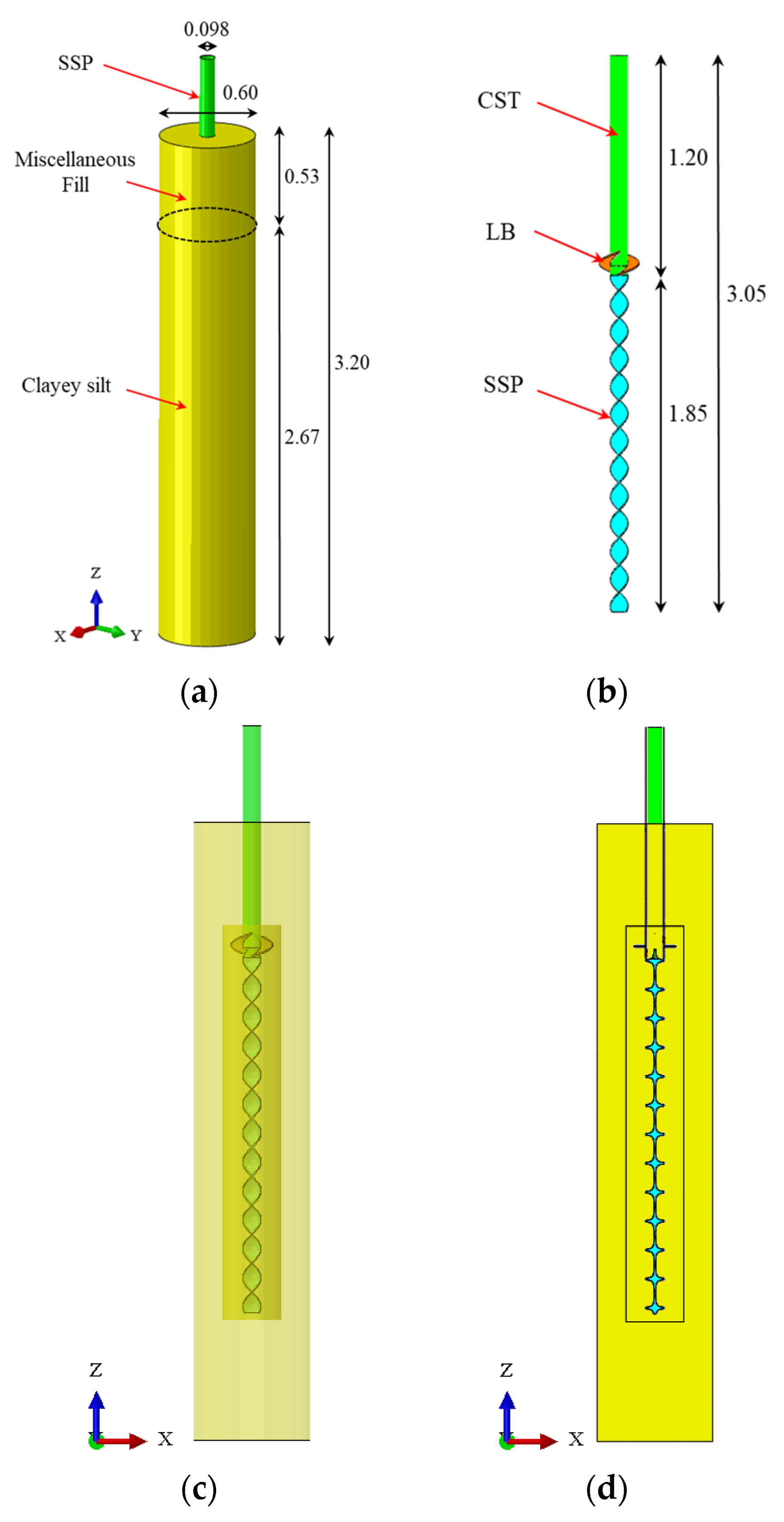
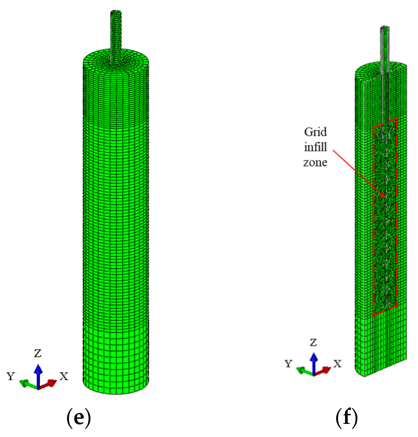
Based on the large-scale general finite-element software ABAQUS, a 3D-FEM of “SSP-stratum” is established, as shown in Figure 2. According to the geological survey report of the construction project site, the model stratum is miscellaneous fill and clayey silt from top to bottom. The model stratum is a cylinder with a diameter of 0.6 m and a height of 3.2 m. The model screw pile is embedded in the stratum, as shown in Figure 2a, and the model material is shown in Table 1. The screw pile of the model is composed of three parts from top to bottom. The upper part is a circular steel pipe with a length of 1.2 m, the middle part is a large blade welded at the bottom of the CSP, and the lower part is a screw pile with a length of 1.85 m. The screw pile goes 5 cm deep into the steel pipe and is welded with the inner wall of the CSP. The detailed dimensions of the screw pile are shown in Figure 2b and Table 2. Figure 2c,d show the perspective view and section view of the model. The steel pipe, large blade, and screw pile are welded with each other, and the contact surface between the three in the model is realized by the “binding” attribute. The contact properties are adopted for the contact surface between the steel pipe, large blade, screw pile, and the soil layer. The normal direction of the contact surface is set as hard contact, the tangential direction is set as friction, and the Coulomb friction constitutive model is adopted. The Mohr–Coulomb elastoplastic constitutive model is used for the model soil, and the ideal elastoplastic constitutive model is used for the steel pipe, large blade, and screw pile. The bottom of the model soil layer is fixed and set as three-dimensional (XYZ), the side is fixed and set as horizontal (XY), and the top is set as a free surface. The horizontal plane (XY) of the model pile is set to fixed, and the vertical (Z) is set to free. C3D8R elements are used for the model soil, steel pipe, large blade, and screw pile. The grid size is set at 0.01–0.03 cm, and a total of 130,650 elements are scattered, as shown in Figure 2e. In order to ensure the calculation accuracy of the model, the grid is densified near the screw pile, and the grid densification area is added, as shown in Figure 2f.

2.3. Working Conditions Setting

According to the engineering design and the test report of the third-party testing agency, the static load field test of φ 89 mm × 3050 mm + blade–screw pile is shown in Table 3. In this paper, the compressive and tensile properties of screw piles are studied from the three aspects of friction coefficient, formation strength and pile type. See Table 4 for the setting of working conditions. The friction coefficient analysis is based on the field test data of the third party, and the real optimal friction coefficient μ is obtained by changing the size of the friction coefficient. By changing the elastic modulus of the stratum, the influence of the stratum strength on the bearing performance of the screw pile is studied. The pile-type analysis studies the influence of pile type on the bearing performance of screw pile by changing the configuration of the screw-pile structure. In the analysis of friction coefficient and stratum strength, the vertical compressive load is 67 kN according to the maximum vertical compressive load in Table 3. As the upper part of the screw pile of the project bears a large downward load, the vertical tension is not the focus of the design. The tensile index is used as a reference, and the upward load is applied according to the characteristic value of the maximum uplift bearing capacity 22.15 kN in Table 3.

2.4. Balance of Geostress

Screw piles need to meet the geostress balance condition before being formally loaded. It is generally divided into two analyses: the first involves collecting the output data of the gravity analysis field for pre-analysis. After the model is established, a gravity analysis is first applied to the entire model. In the analysis step, the ABAQUS restart function is used to record the field output data of the gravity analysis, as well as the number of steps and the incremental steps of the gravity analysis. The second step is formal calculation analysis, with the first step being gravity analysis and the second step being load analysis. Edit the prestressing field in the load settings, enter the number of steps, incremental steps, and odb file address for the first gravity analysis, and the load analysis will meet the geostress balance conditions. The method for setting the balance of geostress can be found in similar research literature [28,29,30,31,32].

3. Analysis of Calculation Results

This section will analyze the pile-soil friction coefficient, formation conditions, and structural type based on the numerical simulation results.

3.1. Friction Coefficient Analysis

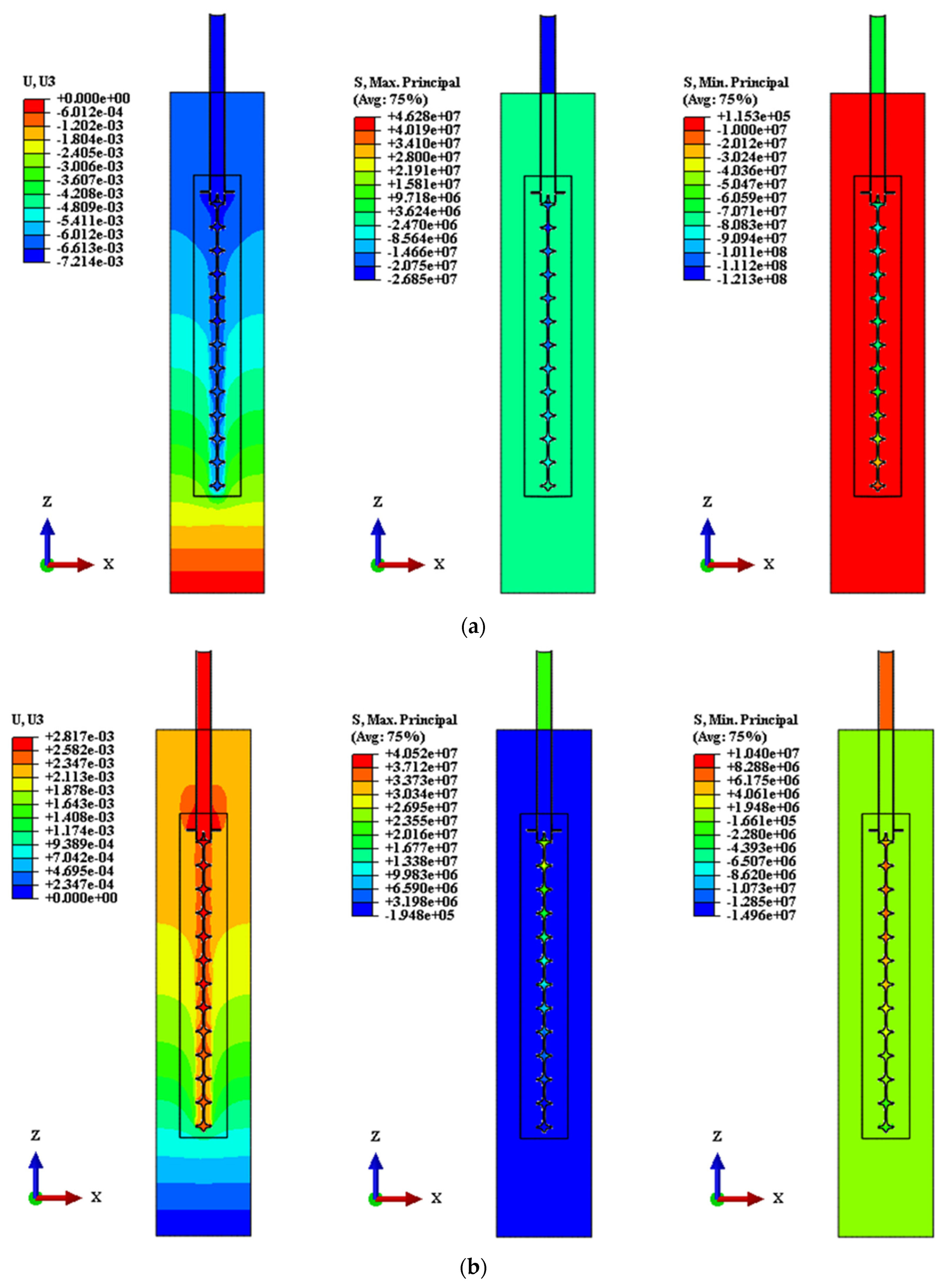
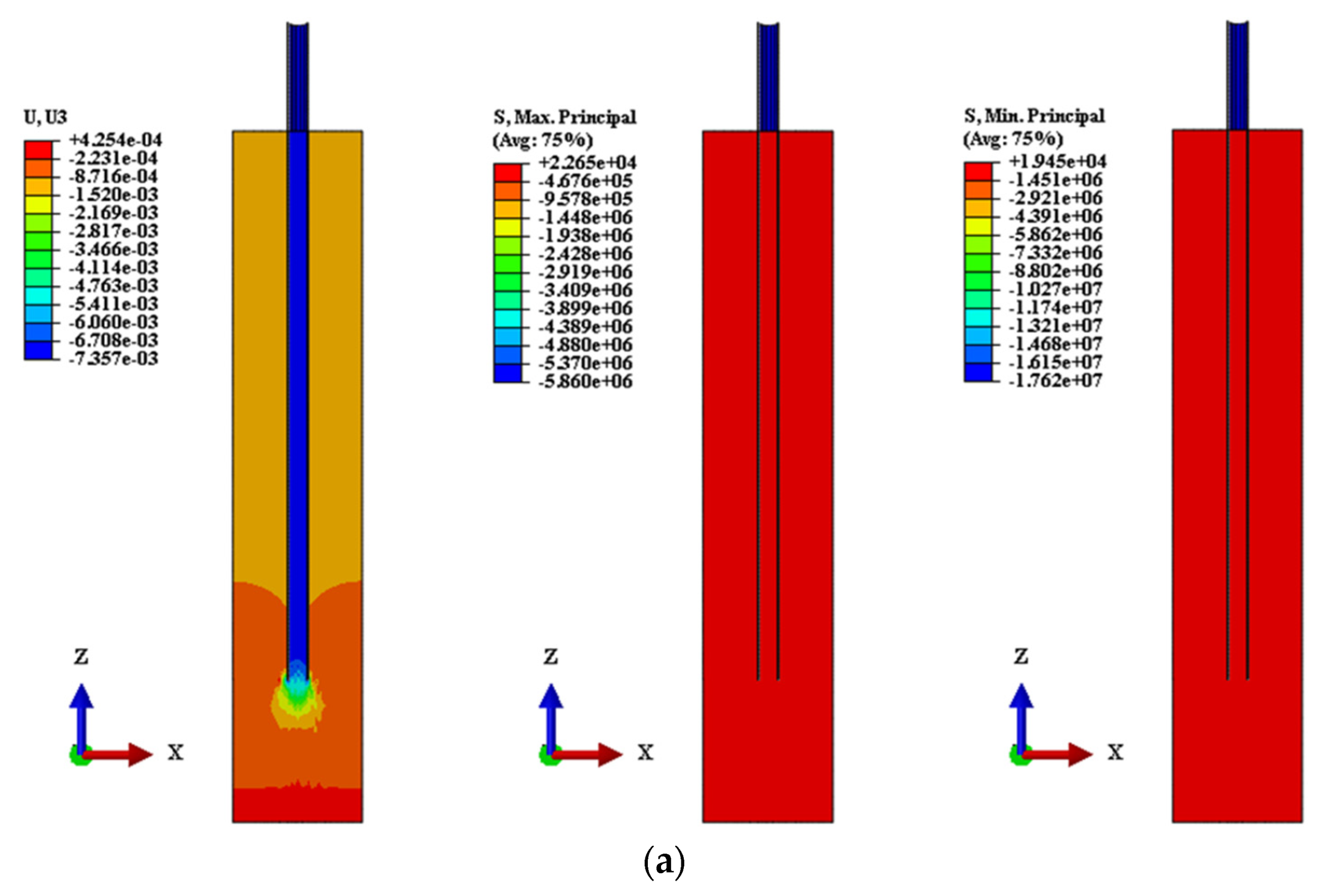
The friction coefficient between the screw pile and the stratum is an important parameter in this study, and the accurate determination of the friction coefficient is the basis of the research on the bearing capacity of the screw pile. According to the working condition settings of friction coefficient analysis in part I of Table 4, this section sets five compression working conditions of C1–C5 and five tension working conditions of C1U–C5U, which, respectively, correspond to the linear assignment of the pile-soil friction coefficient of 0.2–1. Based on the comparison with the field third-party detection data C0, the most accurate and true pile-soil friction coefficient of the project is determined. Among them, the friction coefficient is determined based on the comparison of the settlement value of compression load, and the tension load condition is only used for comparative analysis. The maximum principal stress (MAPS) is used to analyze the tensile performance of screw pile, and the minimum principal stress (MIPS) is used to analyze the compressive performance of screw pile. See Table 5 for the pile-soil friction coefficient analysis, and see Figure 3 for a nephogram of the C3 and C3U working conditions.
It can be seen from Table 5 and Figure 3 that under compressive conditions, the settlement values of C0–C5 under various working conditions are small. The settlement value of C3 is 7.21 mm, which is only 0.96% different from the third-party detection value of 7.28 mm. Therefore, setting the pile-soil friction coefficient to 0.6 has high reliability and accuracy. In addition, the MAPS and MIPS under all working conditions are far less than the elastic limit value of 235 MPa steel. The screw pile under all working conditions is in the elastic working stage, and there is still a large bearing reserve. It can be seen from the tension load condition that the upward lifting amount of C1U–C5U under each condition is small, and the screw pile under each condition is not yielding, which is in the elastic working stage, and the tensile bearing reserve is large.

3.2. Analysis of Stratum Conditions

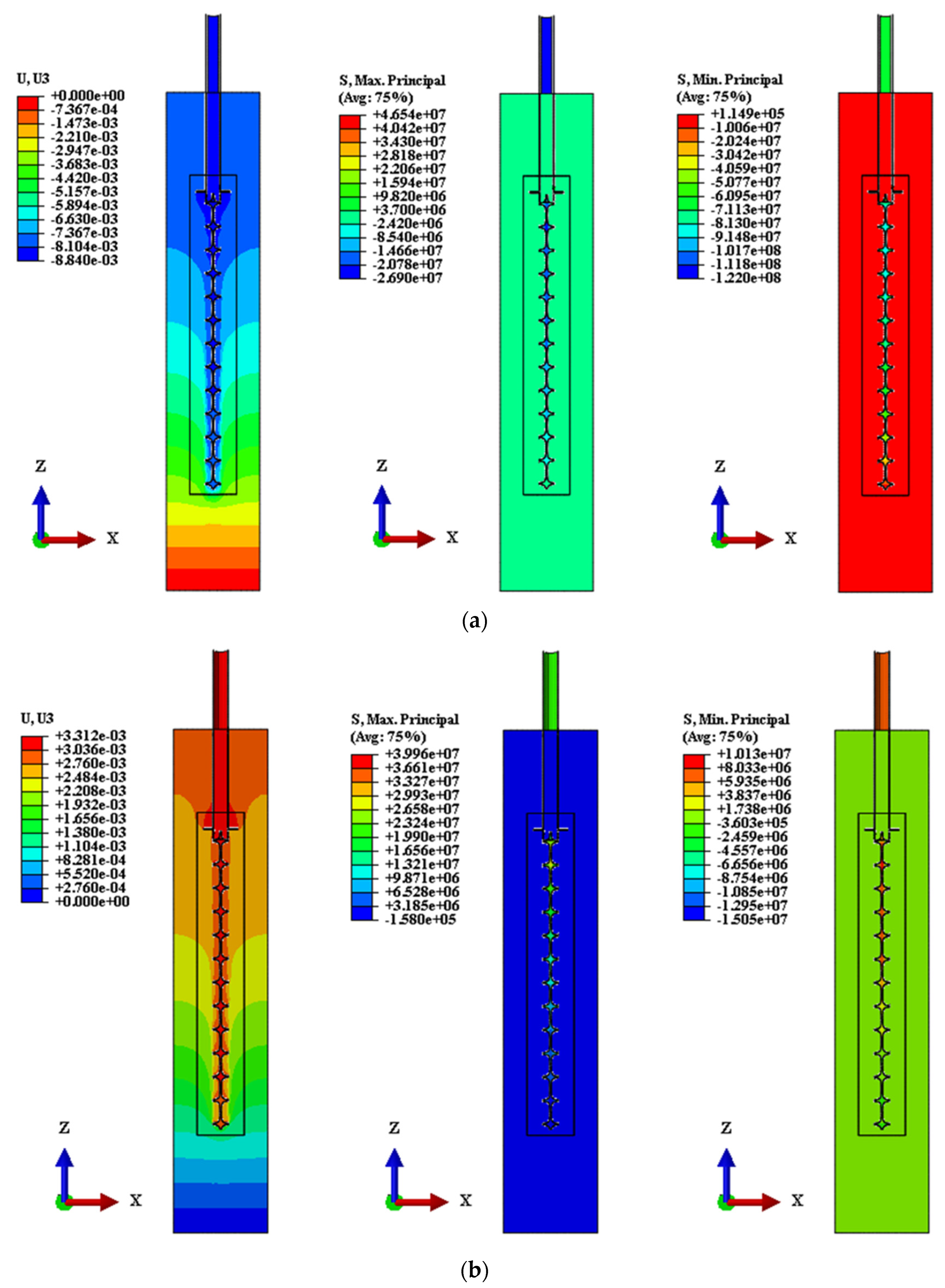
This section studies the influence of stratum conditions on the bearing performance of screw piles. Taking C3 in Section 3.1 as the reference group S2, the Young’s modulus E is 34.5 MPa, the Young’s modulus of S1 is 0.8E, and the Young’s modulus of S3 is 1.2E, as the control group. The tension and compression strength are similar. The analysis of stratum conditions is shown in Table 6, and the nephogram of S1 and S1U in the comparison group is shown in Figure 4.
It can be seen from Table 6 and Figure 4 that under compressive conditions, the settlement value, MAPS, and MIPS of screw pile gradually decrease with the increase in the Young’s modulus of the stratum, and the Young’s modulus is inversely correlated with the settlement value and the extreme value of principal stress. On the whole, the settlement values of screw piles under S1–S3 working conditions are small, and the MAPS and MIPS extrema are far less than the elastic extremum of steel. Screw piles are in the elastic working stage and have large bearing reserves. The tension working condition is similar to the compression working condition; that is, with the increase in Young’s modulus of the stratum, the uplift, MAPS, and MIPS of the screw pile gradually decrease. In conclusion, the increase in the Young’s modulus of the stratum is helpful to improve the bearing (compression and tension) performance of the screw pile.

3.3. Analysis of Structural Type Conditions

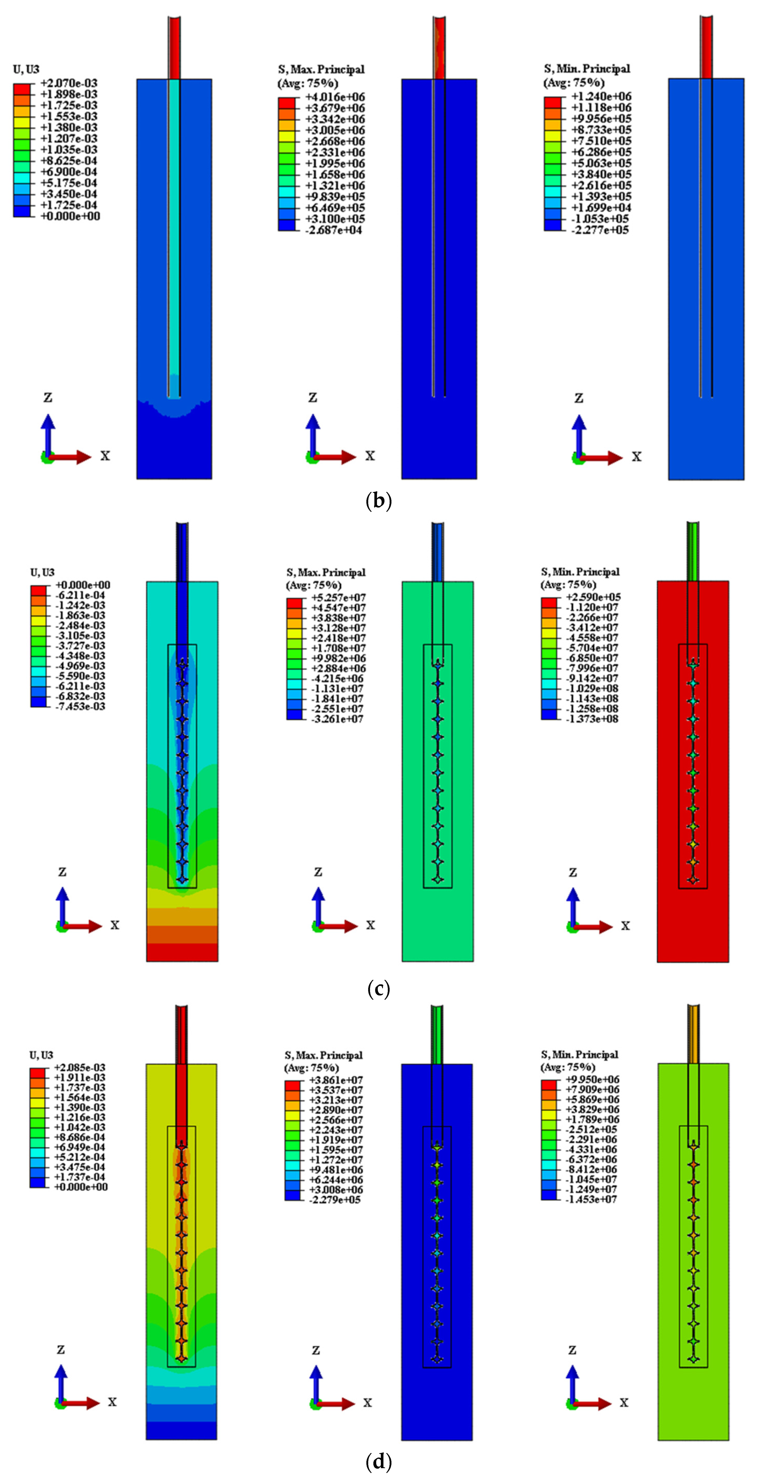
This section studies the influence of the screw-pile structure type on the pile’s bearing performance, taking Section 3.1 C3 as the reference group T3, the CSP + SP type after removing the large blade as the T2 group, and the CSP type with equal height as the T1 group, designated as the control group. The formation parameters are the same, the compression control displacement is greater than 7.28 mm, and the tension control displacement is greater than 2.07 mm. See Table 7 for the structural type analysis, and see Figure 5 for the nephogram of T1, T2, T1U and T2U with larger values in the comparison group.
It can be seen from Table 7 and Figure 5 that under compression conditions, taking the settlement of about 7.28 mm as the reference, the compression capacity of CSP is about 19.83 kN, the compression capacity of CSP + SP is about 2 times higher than that of CSP, and the compression capacity of CST + LB + SP is about 2.4 times higher than that of CSP. The MAPS and MIPS of CSP are relatively small due to its smooth surface and small formation friction coefficient. The addition of screw piles in the CSP + SP structure has greatly improved the bearing performance and the extreme stress. After adding large blades to the CST + LB + SP structure, the bearing performance continues to improve, and the stress extreme value is slightly lower than that of the CSP + SP structure, which indicates that the large blades better bear the load of the screw part, optimize the stress distribution of the structure, and alleviate the stress concentration at the bottom of the screw pile. In the tension condition, taking the design value of about 2.07 mm as the reference, the tension-bearing capacity of CSP is about 3.75 kN, the tension-bearing capacity of CSP + SP is about 3.4 times higher than that of CSP, and the tension-bearing capacity of CST + LB + SP is about 4.9 times higher than that of CSP. In terms of stress extrema, the extremum of the principal stress of the CSP is small. The CSP + SP structure and the CST + LB + SP structure have improved to a certain extent, and the difference is small. The main reason is that both structures are in the stage of elastic deformation, far from reaching the boundary of elastic extremum.

4. Bearing Mechanism of Steel Screw Pile

4.1. Force Analysis

Based on the previous research, the bearing mechanism of steel screw pile is described as follows:
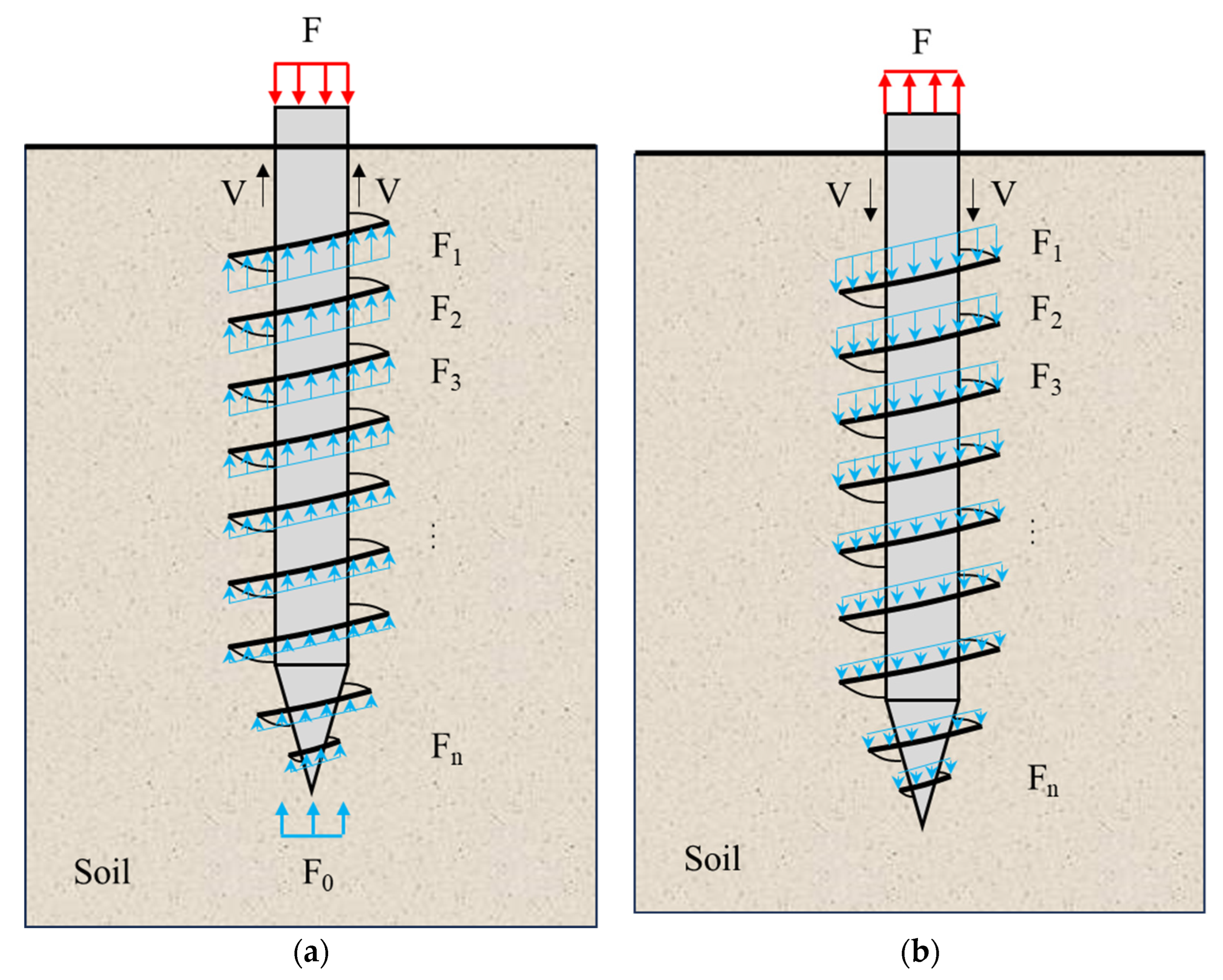
Compression condition: as shown in Figure 6a, the top of the screw pile above the stratum is subjected to a vertical downward uniformly distributed compression load F, the screw pile below the stratum is subjected to pile-soil friction V, the soil-support reaction force F0 at the bottom of the pile, and the soil-support reaction force Fn (n = 1, 2, 3..., the same below) on the screw blade, a total of three vertical reactions, and the normal working force balance state is:
F = V + F 0 + F n n = 1 , 2 , 3
in general, F 1 > F 2 > F 3 > F n .
Tension condition: as shown in Figure 6b, the top of the screw pile above the stratum is subjected to a vertical upward uniformly distributed load F, the screw pile below the stratum is subjected to pile-soil friction V, and the soil-support reaction Fn (n = 1, 2, 3...) is the total of two vertical downward reactions. The normal working force balance state is:
F = V + F n n = 1 , 2 , 3
in general, F 1 > F 2 > F 3 > F n .

4.2. Bearing Failure Criterion

The bearing failure criterion of SSP can be divided into two parts: mechanics and displacement.
Mechanics:
(1)
Compression condition, the pile’s top compressive load is greater than the compressive limit, i.e.,
F > V + F 0 + F n n = 1 , 2 , 3
(2)
Tension condition, the tension load on the pile’s top is greater than the tension limit, i.e.,
F < V + F n n = 1 , 2 , 3
(3)
The screw-blade surface is damaged, that is, the root of the screw-blade surface is damaged by soil shear during the process of upward and downward pressure of the screw pile, and the steel structure is damaged due to yield failure, so its bearing ability is nullified.
F n > V s
where V s is the design value of shear resistance at the root of the screw blade.
Displacement:
When the vertical downward displacement of the screw pile is greater than the design value under the compression load, or when the vertical upward displacement of the screw pile is greater than the design value under tension load, the bearing failure of screw pile can be determined.
To sum up, the bearing design of steel screw piles should meet the control requirements of mechanics and deformation at the same time.

5. Conclusions

Based on an emergency project in Daxing District, Beijing, the bearing mechanism of SSP is studied. The 3D-FEM is established through the ABAQUS finite-element numerical simulation analysis platform. Based on the real engineering load simulation and field detection, a simulation analysis and comparative research are carried out. The following conclusions are obtained:
(1)
Based on the numerical simulation of the friction coefficient condition and the comparative analysis of the field monitoring results, the pile-soil friction coefficient is about 0.6 under the stratum condition. The MAPS and MIPS under compression and tension are far less than the elastic limit value of 235 MPa steel. The screw pile under each working condition is in the elastic working stage, and there is still a large bearing reserve.
(2)
With the increase in the Young’s modulus of the stratum, the settlement value, MAPS and MIPS of the screw pile gradually decrease, and the Young’s modulus is inversely correlated with the settlement value and the extreme value of the principal stress. The tension load condition is similar to the compression condition. The increase in the Young’s modulus of the stratum is helpful to improve the bearing capacity (compressive and tensile load) of the screw pile.
(3)
Under compressive conditions, the compressive capacity of CST + SP is about 2 times higher than that of CST, and the compressive capacity of CST + LB + SP is about 2.4 times higher than that of CST. Under tensile conditions, the uplift bearing capacity of CST + SP is about 3.4 times higher than that of CST, and the uplift bearing capacity of CST + LB + SP is about 4.9 times higher than that of CST. The setting of large blades better bears the load of the screw part, optimizes the stress distribution of the structure, and alleviates the stress concentration at the bottom of the screw pile.
(4)
Based on the mechanical analysis in the vertical direction, the bearing mechanism of SSP under the compression and tension conditions is elaborated. The bearing failure criterion of SSP is summarized from the aspects of mechanics and displacement. The bearing design of SSP should meet the control requirements of mechanics and deformation at the same time.

Author Contributions

Conceptualization, P.D. and Y.L.; methodology, P.D.; software, P.D.; validation, Y.L., C.S. and F.M.; investigation, C.S. and Z.D.; resources, W.L.; data curation, X.C.; writing—original draft preparation, P.D.; writing—review and editing, C.S.; supervision, W.L. and X.C.; project administration, P.D.; funding acquisition, X.C. All authors have read and agreed to the published version of the manuscript.

Funding

The authors gratefully acknowledgement the financial support provided by the China Construction First Bureau R & D Plan (No. KJYF-2022-18, No. KJYF-2022-24, No. KJYF-2022-25), China Construction First Bureau Group South China Construction R & D Plan (No. KJYF-HN-2024-6, No. KJYF-HN-2024-8).

Data Availability Statement

The data presented in this study are available on request from the corresponding author.

Conflicts of Interest

Authors Peng Ding, Yang Liu, Fanguang Meng and Wei Li were employed by the company China Construction First Bureau Group South China Construction Co., Ltd. The remaining authors declare that the research was conducted in the absence of any commercial or financial relationships that could be construed as a potential conflict of interest.

References

  1. AbdelSalam, S.S.; Sritharan, S.; Suleiman, M.T. Current Design and Construction Practices of Bridge Pile Foundations with Emphasis on Implementation of LRFD. J. Bridg. Eng. 2010, 15, 749–758. [Google Scholar] [CrossRef]
  2. Eskişar, T.; Otani, J.; Hironaka, J. Visualization of soil arching on reinforced embankment with rigid pile foundation using X-ray CT. Geotext. Geomembranes 2012, 32, 44–54. [Google Scholar] [CrossRef]
  3. Xu, Q.; Zhu, H.; Ma, X.; Ma, Z.; Li, X.; Tang, Z.; Zhuo, K. A case history of shield tunnel crossing through group pile foundation of a road bridge with pile underpinning technologies in Shanghai. Tunn. Undergr. Space Technol. 2015, 45, 20–33. [Google Scholar] [CrossRef]
  4. Vignesh, V.; Mayakrishnan, M. Design parameters and behavior of helical piles in cohesive soils—A review. Arab. J. Geosci. 2020, 13, 1–14. [Google Scholar] [CrossRef]
  5. Ravi, K.R.; Gunneswara, R. Experimental study of a modeled building frame supported by pile groups embedded in cohesionless soil. Interact. Multiscale Mech. 2011, 4, 321–336. [Google Scholar] [CrossRef]
  6. Li, G.; Yu, Q.; Ma, W.; Mu, Y.; Li, X.; Chen, Z. Laboratory testing on heat transfer of frozen soil blocks used as backfills of pile foundation in permafrost along Qinghai-Tibet electrical transmission line. Arab. J. Geosci. 2015, 8, 2527–2535. [Google Scholar] [CrossRef]
  7. Perko, H.A. Helical Piles: A Practical Guide to Design and Installation, 1st ed.; John Wiley & Sons: Hoboken, NJ, USA, 2009. [Google Scholar]
  8. Sakr, M. Performance of helical piles in oil sand. Can. Geotech. J. 2009, 46, 1046–1061. [Google Scholar] [CrossRef]
  9. A. B. Chance Co. Helical Pier Foundation Systems, Bulletin; Hubbell Inc.: Centralia, MO, USA, 2000; pp. 1–12. [Google Scholar]
  10. Trofimenkov, J.G.; Maruipolshii, L.G. Screw piles used for mast and tower foundations. In Proceedings of the 6th International Conference on Soil Mechanics and Foundation Engineering, Montreal, QC, Canada, 8–15 September 1965; National Academy of Sciences: Washington, DC, USA, 2004; pp. 328–332. [Google Scholar]
  11. Adams, J.I.; Klym, T.W. A study of anchors for transmission tower foundations. Can. Geotech. J. 1972, 9, 89–104. [Google Scholar] [CrossRef]
  12. Mitsch, M.P.; Clemence, S.P. The uplift capacity of helix anchors in sand. In Uplift Behaviour of Anchor Foundations in Soil; American Society of Civil Engineers: Reston, VA, USA, 1985; pp. 26–47. [Google Scholar]
  13. Mooney, J.S.; Adamczak, S.; Clemence, S.P. Uplift Capacity of Helix Anchors in Clay and Silt; American Society of Civil Engineers: Reston, VA, USA, 1985; pp. 48–72. [Google Scholar]
  14. Sakr, M. Lateral resistance of high capacity helical piles: Case study. In Proceedings of the 63rd Canadian Geotechnical and 6th Canadian Permafrost Conference, Calgary, AB, Canada, 12–16 September 2010; Canadian Geotechnical Society: Surrey, BC, Canada, 2010; pp. 405–413. [Google Scholar]
  15. Schmidt, R.; Nasr, M. Screw piles: Uses and considerations. Struct. Mag. 2004, 21, 29–31. [Google Scholar]
  16. Zhang, D.J.Y.; Chalaturnyk, R.; Robertson, P.K.; Sego, D.C.; Cyre, G. Screw anchor test program (Part I & II): Instrumentation, site characterization and installation. In Geotechnique and Resources, Proceedings of the 51st Canadian Geotechnical Conference, Edmonton, AB, Canada, 4–7 October 1988; Canadian Geotechnical Society: Surrey, BC, Canada, 1998. [Google Scholar]
  17. Livneh, B.; Naggar, M.H.M. Axial testing and numerical modelling of square shaft helical piles under compressive and tensile loading. Can. Geotech. J. 2008, 45, 1142–1155. [Google Scholar] [CrossRef]
  18. Vickars, R.; Clemence, S.P. Performance of helical piles with grouted shafts. In New Technological and Design Developments in Deep Foundations; American Society of Civil Engineers: Reston, VA, USA, 2000; pp. 327–341. [Google Scholar]
  19. Yttrup, P.J.; Abramsson, G. Ultimate strength of steel screw piles in sand. Aust. Geomech. J. News Aust. Geomech. Soc. 2003, 38, 17–27. [Google Scholar]
  20. Demir, A.; Ok, B. Uplift response of multi-plate helical anchors in cohesive soil. Geomech. Eng. 2015, 8, 615–630. [Google Scholar] [CrossRef]
  21. Knappett, L.; Brown, M.J.; Brennan, A.J.; Hamilton, L. Optimising the compressive behavior of screw piles in sand for marine renewable energy application. In Proceedings of the DFI/EFFC 11th International Conference on Piling and Deep Foundations, Stockholm, Sweden, 21–23 May 2014; Deep Foundations Institute: Hawthorne, NJ, USA, 2014. [Google Scholar]
  22. Mittal, S.; Mukherjee, S. Behaviour of group of helical screw anchors under compressive loads. Geotech. Geol. Eng. 2015, 33, 575–592. [Google Scholar] [CrossRef]
  23. Papadopoulou, K.; Saroglou, H.; Papadopoulos, V. Finite Element Analyses and Experimental Investigation of Helical Micropiles. Geotech. Geol. Eng. 2014, 32, 949–963. [Google Scholar] [CrossRef]
  24. Polishchuk, A.I.; Maksimov, F.A. Improved design for settlement of helical pile in clay. IOP Conf. Series: Mater. Sci. Eng. 2018, 451, 012110. [Google Scholar] [CrossRef]
  25. Rawat, S.; Gupta, A.K. Numerical modelling of pullout of helical soil nail. J. Rock Mech. Geotech. Eng. 2017, 9, 648–658. [Google Scholar] [CrossRef]
  26. Sakr, M. Performance of laterally loaded helical piles in clayey soils established from field experience. DFI J.–J. Deep. Found. Inst. 2018, 12, 28–41. [Google Scholar] [CrossRef]
  27. Salhi, L.; Nait-Rabah, O.; Deyrat, C.; Roos, C. Numerical modeling of single helical pile behavior under compressive loading in sand. Electron. J. Geotech. Eng. 2013, 18, 4319–4338. [Google Scholar]
  28. Ding, P.; Shi, C.; Tao, L.; Liu, Z.; Zhang, T. Research on seismic analysis methods of large and complex underground pipe structures in hard rock sites. Tunn. Undergr. Space Technol. 2023, 135, 105035. [Google Scholar] [CrossRef]
  29. Ding, P.; Tao, L.; Yang, X.; Zhao, J.; Shi, C. Three-dimensional dynamic response analysis of a single-ring structure in a prefabricated subway station. Sustain. Cities Soc. 2019, 45, 271–286. [Google Scholar] [CrossRef]
  30. Shi, C.; Tao, L.; Ding, P.; Wang, Z.; Jia, Z. Study on seismic response characteristics and failure mechanism of giant-span flat cavern. Tunn. Undergr. Space Technol. 2023, 140, 105328. [Google Scholar] [CrossRef]
  31. Tao, L.; Shi, C.; Ding, P.; Li, S.; Wu, S.; Bao, Y. A study on bearing characteristic and failure mechanism of thin-walled structure of a prefabricated subway station. Front. Struct. Civ. Eng. 2022, 16, 359–377. [Google Scholar] [CrossRef]
  32. Tao, L.; Ding, P.; Lin, H.; Wang, H.; Kou, W.; Shi, C.; Li, S.; Wu, S. Three-dimensional seismic performance analysis of large and complex underground pipe trench structure. Soil Dyn. Earthq. Eng. 2021, 150, 106904. [Google Scholar] [CrossRef]
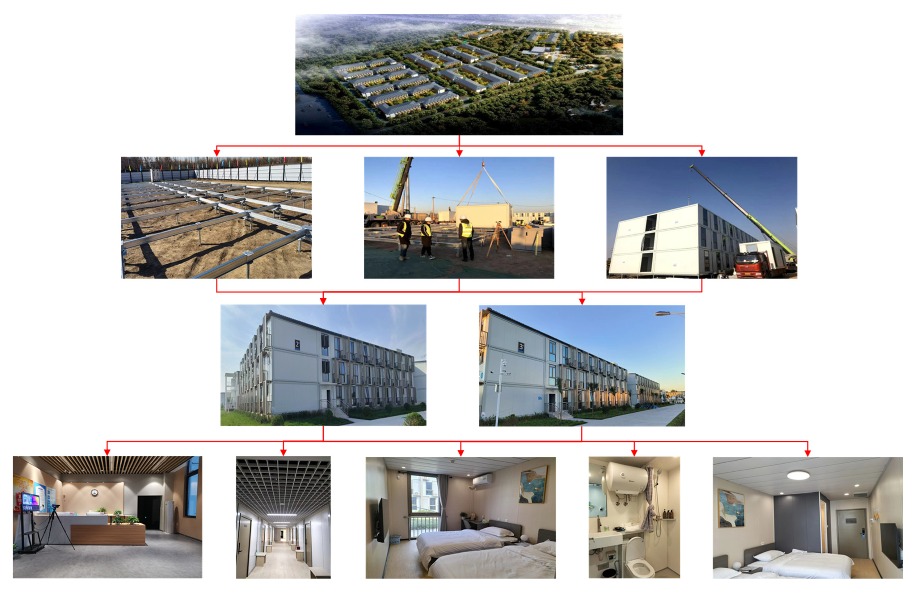
Figure 1. An emergency construction project in Beijing.
Buildings 14 03376 g001
Figure 2. Three-dimensional finite element model of φ 89 mm × 3050 mm + blade–steel screw pile stratum (unit: m): (a) model size; (b) pile size; (c) perspective view; (d) section; (e) grid elevation and (f) grid section.
Buildings 14 03376 g002aBuildings 14 03376 g002b
Figure 3. Nephogram of pile-soil friction coefficient analysis (displacement unit: m, stress unit: Pa) (a) maximum settlement, MAPS, and MIPS under C3 and (b) maximum uplift, MAPS, and MIPS under C3U.
Buildings 14 03376 g003
Figure 4. Nephogram of the analysis of stratum conditions (displacement unit: m, stress unit: Pa) (a) maximum settlement, MAPS, and MIPS under S1, and (b) maximum uplift, MAPS, and MIPS under S1U.
Buildings 14 03376 g004
Figure 5. Nephogram of the analysis of structural-type conditions (displacement unit: m, stress unit: Pa) (a) maximum settlement, MAPS, and MIPS under T1, (b) maximum uplift, MAPS and MIPS under T1U, (c) maximum settlement, MAPS and MIPS under T2 and (d) maximum uplift, MAPS, and MIPS under T2U.
Buildings 14 03376 g005aBuildings 14 03376 g005b
Figure 6. Schematic diagram of bearing mechanism of SSP: (a) compression condition and (b) tension condition.
Buildings 14 03376 g006
Table 1. Material properties.
NameThickness d (m)Density ρ (kg/m3)Young’s Modulus E (MPa)Poisson’s Ratio νCohesion c (kPa)Internal Friction Angle φ (°)
Miscellaneous Fill0.531850230.3410
Clayey silt2.67195034.50.281328
Q235B steel0.0087850206,0000.25--
Table 2. Steel screw pile size.
NameThickness (m)Height (m)Outside Diameter (m)Spiral RingPitch (m)Thread Inclination (°)
Circular steel tube0.00351.20.089000
Large blade0.0080.1180.20710.11829.5
Screw pile0.0081.840.096120.1556.6
Table 3. Single-pile static load test.
NameDesign the Characteristic Value of Vertical Compressive Bearing Capacity (kN)Design the Vertical Compressive Bearing Capacity Characteristic Value Corresponding to the Settlement Amount (mm)Maximum Vertical Compressive Loading Capacity (kN)The Maximum Vertical Compressive Loading Corresponds to the Settlement Amount (mm)Design the Characteristic Value of Vertical Tensile Bearing Capacity (kN)Design the Characteristic Value of Vertical Anti Pull Bearing Capacity Corresponding to the Uplift Amount (mm)
φ 89 mm
× 3050 mm
+ blade–screw pile
44.304.14677.2822.15
(Half compression)
2.07
(Half compression)
Value-taking methodDesign valueActual measurement valueDesign valueActual measurement valueExperience valueExperience value
ImportanceControlControlControlControlReferenceReference
Table 4. Working condition settings.
No.Friction CoefficientYoung’s Modulus EPile TypeControl MethodNote
Friction coefficient analysisC10.2Same as Table 1CST + LB + SP (Same size as Table 2)Load control: load 67 kN downwards from the top (design value)/Compared with on-site test data, obtain the true optimal friction coefficient μ.
C20.4
C30.6
C40.8
C51
C1U0.2/Load control: load 22.15 kN upwards from the top (experience value)
C2U0.4
C3U0.6
C4U0.8
C5U1
Stratum strength analysisS1μ0.8ECST + LB + SP (Same size as Table 2)Load control: load 67 kN downwards from the top (design value)/Study on the influence of geological strength on the bearing performance of screw piles.
S2E
S31.2E
S1U0.8E/Load control: load 22.15 kN upwards from the top (experience value)
S2UE
S3U1.2E
Pile type analysisT1μSame as Table 1CSTDisplacement control: downward settlement of 7.28 mm (measured value)/Study on the influence of pile type on the bearing performance of screw piles.
T2CST+SP
T3CST + LB + SP
T1UCST/Displacement control: downward settlement of 7.28 mm (measured value)
T2UCST+SP
T3UCST + LB + SP
Table 5. Analysis of pile-soil friction coefficient.
No.Friction CoefficientLoad
(kN)
Settlement/Uplift (mm)Difference (%)MAPS (MPa)MIPS (MPa)Conclusion/Description
C0/67 ↓7.28///Design value, detection value
C10.267 ↓4.48−38.4627.3071.03The settlement under all working conditions is small, C3 working condition is the closest to the detection value, and all working conditions are not yielding, which is in the elastic working stage.
C20.467 ↓5.85−19.6436.8295.92
C30.667 ↓7.21−0.9646.28121.30
C40.867 ↓7.17−1.5146.30121.50
C5167 ↓7.16−1.6446.20121.30
C0U/22.5 ↑////Experience value
C1U0.222.5 ↑3.15/39.4914.76Under all working conditions, the upward lifting amount is small and does not yield, so it is in the elastic working stage.
C2U0.422.5 ↑2.84/39.6414.93
C3U0.622.5 ↑2.82/39.614.95
C4U0.822.5 ↑2.69/39.5214.93
C5U122.5 ↑2.67/39.6214.91
Note: ↓ indicates that the load is vertically downward, ↑ indicates that the load is vertically upward, and the difference = (CX − C0)/C0 × 100%.
Table 6. Analysis of stratum conditions.
No.Young’s Modulus
E (MPa)
Load
(kN)
Settlement/Uplift (mm)Difference (%)MAPS (MPa)MIPS (MPa)Conclusion/Description
S0/67 ↓7.280//Design value, detection value
S10.8E67 ↓8.8421.4346.54122S2 = C3, the settlement under each working condition is small; with the increase in Young’s modulus, the settlement value and principal stress gradually decrease, and the settlement under each working condition is not yielding, so it is in the elastic working stage.
S2E = 34.567 ↓7.21−0.9646.28121.30
S31.2E67 ↓6.1315.8036.8295.92
S0U/22.5 ↑////Experience value
S1U0.8E22.5 ↑3.31/39.9615.05S2U = C3U, with the increase in Young’s modulus, the upward lifting amount and principal stress gradually decrease, and the upward lifting amount and principal stress under all working conditions are small, which are not yielding, and are in Young’s working stage, with large safety reserves.
S2UE = 34.522.5 ↑2.82/39.6014.95
S3U1.2E22.5 ↑2.84/39.2914.88
Note: ↓ indicates that the load is vertically downward, ↑ indicates that the load is vertically upward, and the difference = (SX − S0)/S0 × 100%.
Table 7. Analysis of structural type conditions.
No.Young’s Modulus
E (MPa)
Load
(kN)
Settlement/Uplift (mm)Difference (%)MAPS (MPa)MIPS (MPa)Conclusion/Description
T0/Down ≥ 7.2867 ↓///Design value, detection value
T1CSP7.3519.83 ↓00.0217.62Taking the settlement of the design value of about 7.28 mm as a reference, the bearing capacity of the CSP + SP is increased by about 2 times, and the bearing capacity of the CST + LB + SP is increased by about 2.4 times.
T2CSP + SP7.4559.66 ↓200.8652.57137.30
T3CST + LB + SP7.2867 ↓237.8746.28121.30
T0U/Up ≥ 2.0722.15 ↑///Experience value
T1UCSP2.073.75 ↑04.020.23Taking the design value of about 2.07 mm as a reference, the uplift bearing capacity of CSP + SP is increased by about 3.4 times, and that of CST + LB + SP is increased by about 4.9 times.
T2UCSP + SP2.0916.48 ↑339.4738.6114.53
T3UCST + LB + SP2.8222.15 ↑490.6739.6014.95
Note: ↓ indicates that the load is vertically downward, ↑ indicates that the load is vertically upward, and the difference = (TX − T1)/T1 × 100%.
Disclaimer/Publisher’s Note: The statements, opinions and data contained in all publications are solely those of the individual author(s) and contributor(s) and not of MDPI and/or the editor(s). MDPI and/or the editor(s) disclaim responsibility for any injury to people or property resulting from any ideas, methods, instructions or products referred to in the content.