

Study on Bearing Mechanism of Steel Screw Pile
 ,
,  and
and
Abstract
1. Introduction
2. Establishment 3D Finite Element Model
2.1. Engineering Background
2.2. Three-Dimensional-FEM
2.3. Working Conditions Setting
2.4. Balance of Geostress
3. Analysis of Calculation Results
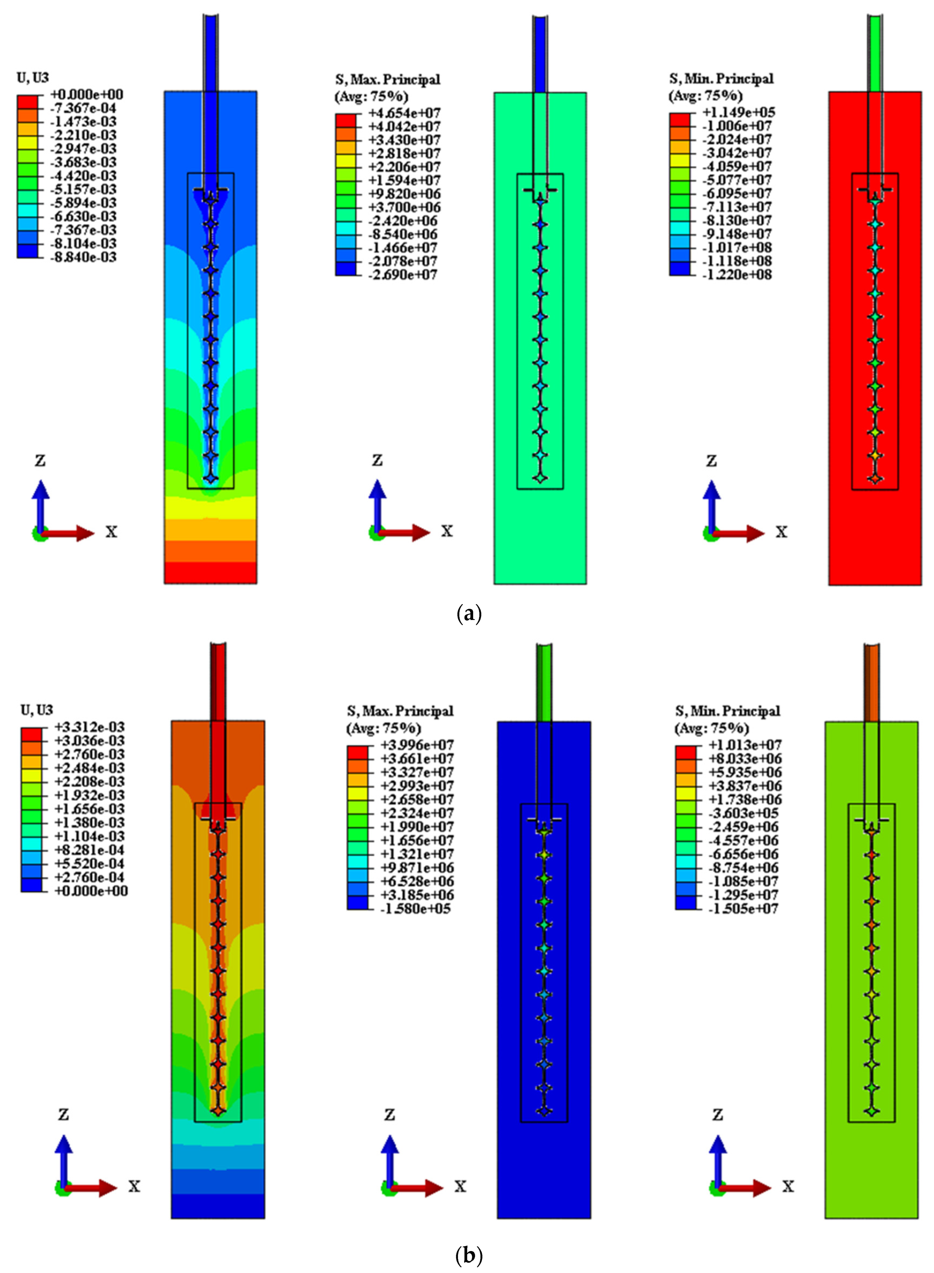
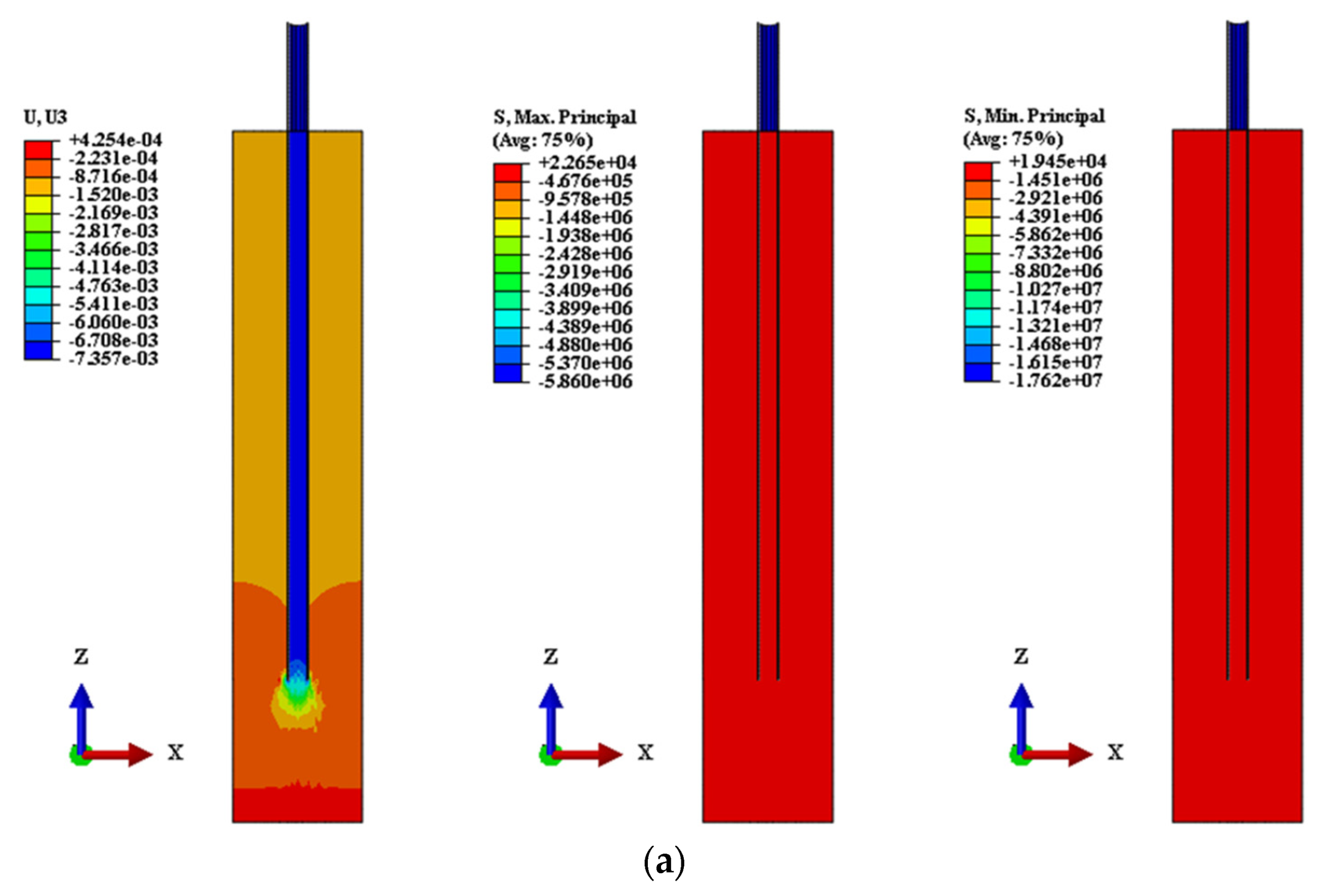
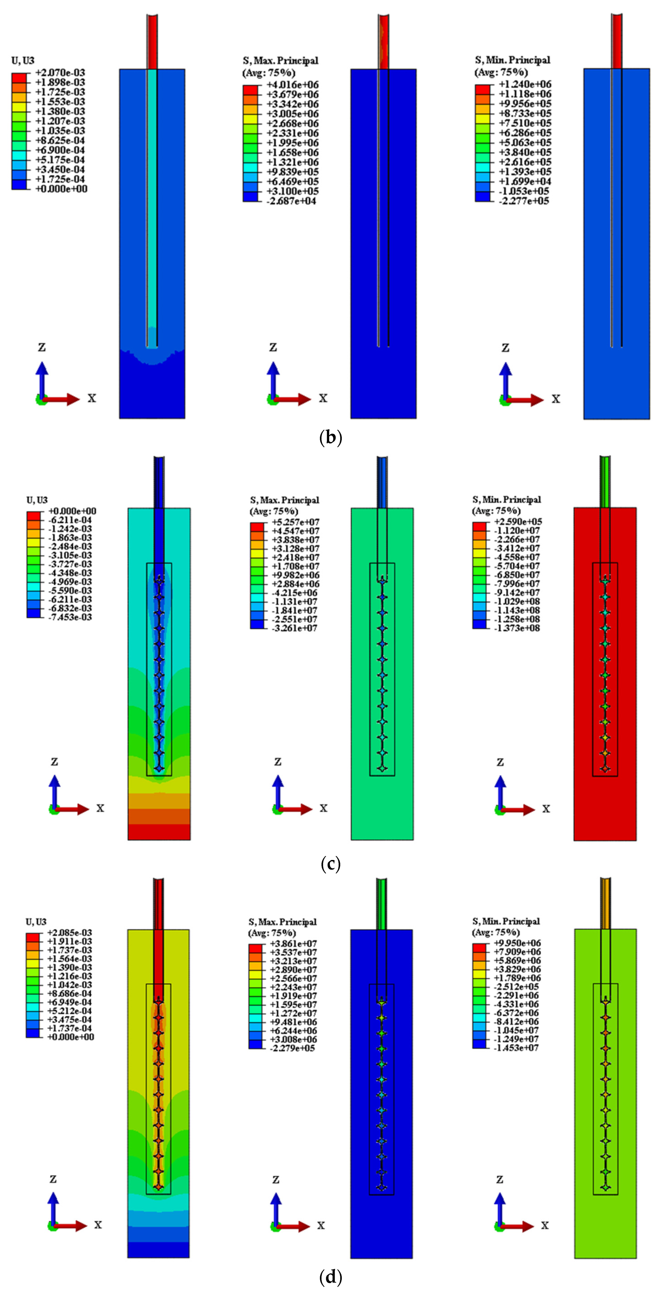
3.1. Friction Coefficient Analysis
3.2. Analysis of Stratum Conditions
3.3. Analysis of Structural Type Conditions
4. Bearing Mechanism of Steel Screw Pile
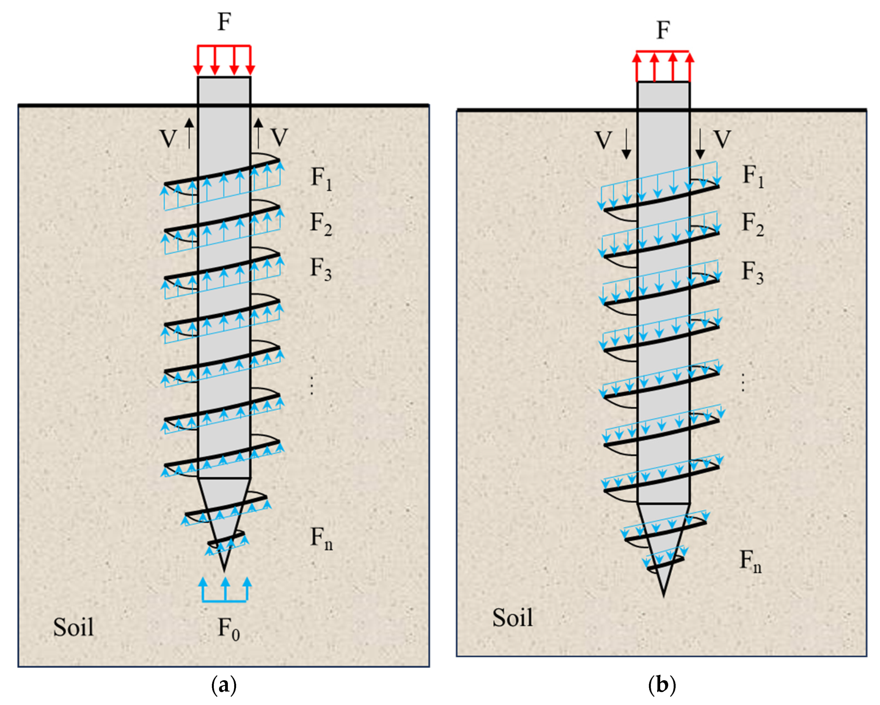
4.1. Force Analysis
4.2. Bearing Failure Criterion
- (1)
- Compression condition, the pile’s top compressive load is greater than the compressive limit, i.e.,
- (2)
- Tension condition, the tension load on the pile’s top is greater than the tension limit, i.e.,
- (3)
- The screw-blade surface is damaged, that is, the root of the screw-blade surface is damaged by soil shear during the process of upward and downward pressure of the screw pile, and the steel structure is damaged due to yield failure, so its bearing ability is nullified.
5. Conclusions
- (1)
- Based on the numerical simulation of the friction coefficient condition and the comparative analysis of the field monitoring results, the pile-soil friction coefficient is about 0.6 under the stratum condition. The MAPS and MIPS under compression and tension are far less than the elastic limit value of 235 MPa steel. The screw pile under each working condition is in the elastic working stage, and there is still a large bearing reserve.
- (2)
- With the increase in the Young’s modulus of the stratum, the settlement value, MAPS and MIPS of the screw pile gradually decrease, and the Young’s modulus is inversely correlated with the settlement value and the extreme value of the principal stress. The tension load condition is similar to the compression condition. The increase in the Young’s modulus of the stratum is helpful to improve the bearing capacity (compressive and tensile load) of the screw pile.
- (3)
- Under compressive conditions, the compressive capacity of CST + SP is about 2 times higher than that of CST, and the compressive capacity of CST + LB + SP is about 2.4 times higher than that of CST. Under tensile conditions, the uplift bearing capacity of CST + SP is about 3.4 times higher than that of CST, and the uplift bearing capacity of CST + LB + SP is about 4.9 times higher than that of CST. The setting of large blades better bears the load of the screw part, optimizes the stress distribution of the structure, and alleviates the stress concentration at the bottom of the screw pile.
- (4)
- Based on the mechanical analysis in the vertical direction, the bearing mechanism of SSP under the compression and tension conditions is elaborated. The bearing failure criterion of SSP is summarized from the aspects of mechanics and displacement. The bearing design of SSP should meet the control requirements of mechanics and deformation at the same time.
Author Contributions
Funding
Data Availability Statement
Conflicts of Interest
References
- AbdelSalam, S.S.; Sritharan, S.; Suleiman, M.T. Current Design and Construction Practices of Bridge Pile Foundations with Emphasis on Implementation of LRFD. J. Bridg. Eng. 2010, 15, 749–758. [Google Scholar] [CrossRef]
- Eskişar, T.; Otani, J.; Hironaka, J. Visualization of soil arching on reinforced embankment with rigid pile foundation using X-ray CT. Geotext. Geomembranes 2012, 32, 44–54. [Google Scholar] [CrossRef]
- Xu, Q.; Zhu, H.; Ma, X.; Ma, Z.; Li, X.; Tang, Z.; Zhuo, K. A case history of shield tunnel crossing through group pile foundation of a road bridge with pile underpinning technologies in Shanghai. Tunn. Undergr. Space Technol. 2015, 45, 20–33. [Google Scholar] [CrossRef]
- Vignesh, V.; Mayakrishnan, M. Design parameters and behavior of helical piles in cohesive soils—A review. Arab. J. Geosci. 2020, 13, 1–14. [Google Scholar] [CrossRef]
- Ravi, K.R.; Gunneswara, R. Experimental study of a modeled building frame supported by pile groups embedded in cohesionless soil. Interact. Multiscale Mech. 2011, 4, 321–336. [Google Scholar] [CrossRef]
- Li, G.; Yu, Q.; Ma, W.; Mu, Y.; Li, X.; Chen, Z. Laboratory testing on heat transfer of frozen soil blocks used as backfills of pile foundation in permafrost along Qinghai-Tibet electrical transmission line. Arab. J. Geosci. 2015, 8, 2527–2535. [Google Scholar] [CrossRef]
- Perko, H.A. Helical Piles: A Practical Guide to Design and Installation, 1st ed.; John Wiley & Sons: Hoboken, NJ, USA, 2009. [Google Scholar]
- Sakr, M. Performance of helical piles in oil sand. Can. Geotech. J. 2009, 46, 1046–1061. [Google Scholar] [CrossRef]
- A. B. Chance Co. Helical Pier Foundation Systems, Bulletin; Hubbell Inc.: Centralia, MO, USA, 2000; pp. 1–12. [Google Scholar]
- Trofimenkov, J.G.; Maruipolshii, L.G. Screw piles used for mast and tower foundations. In Proceedings of the 6th International Conference on Soil Mechanics and Foundation Engineering, Montreal, QC, Canada, 8–15 September 1965; National Academy of Sciences: Washington, DC, USA, 2004; pp. 328–332. [Google Scholar]
- Adams, J.I.; Klym, T.W. A study of anchors for transmission tower foundations. Can. Geotech. J. 1972, 9, 89–104. [Google Scholar] [CrossRef]
- Mitsch, M.P.; Clemence, S.P. The uplift capacity of helix anchors in sand. In Uplift Behaviour of Anchor Foundations in Soil; American Society of Civil Engineers: Reston, VA, USA, 1985; pp. 26–47. [Google Scholar]
- Mooney, J.S.; Adamczak, S.; Clemence, S.P. Uplift Capacity of Helix Anchors in Clay and Silt; American Society of Civil Engineers: Reston, VA, USA, 1985; pp. 48–72. [Google Scholar]
- Sakr, M. Lateral resistance of high capacity helical piles: Case study. In Proceedings of the 63rd Canadian Geotechnical and 6th Canadian Permafrost Conference, Calgary, AB, Canada, 12–16 September 2010; Canadian Geotechnical Society: Surrey, BC, Canada, 2010; pp. 405–413. [Google Scholar]
- Schmidt, R.; Nasr, M. Screw piles: Uses and considerations. Struct. Mag. 2004, 21, 29–31. [Google Scholar]
- Zhang, D.J.Y.; Chalaturnyk, R.; Robertson, P.K.; Sego, D.C.; Cyre, G. Screw anchor test program (Part I & II): Instrumentation, site characterization and installation. In Geotechnique and Resources, Proceedings of the 51st Canadian Geotechnical Conference, Edmonton, AB, Canada, 4–7 October 1988; Canadian Geotechnical Society: Surrey, BC, Canada, 1998. [Google Scholar]
- Livneh, B.; Naggar, M.H.M. Axial testing and numerical modelling of square shaft helical piles under compressive and tensile loading. Can. Geotech. J. 2008, 45, 1142–1155. [Google Scholar] [CrossRef]
- Vickars, R.; Clemence, S.P. Performance of helical piles with grouted shafts. In New Technological and Design Developments in Deep Foundations; American Society of Civil Engineers: Reston, VA, USA, 2000; pp. 327–341. [Google Scholar]
- Yttrup, P.J.; Abramsson, G. Ultimate strength of steel screw piles in sand. Aust. Geomech. J. News Aust. Geomech. Soc. 2003, 38, 17–27. [Google Scholar]
- Demir, A.; Ok, B. Uplift response of multi-plate helical anchors in cohesive soil. Geomech. Eng. 2015, 8, 615–630. [Google Scholar] [CrossRef]
- Knappett, L.; Brown, M.J.; Brennan, A.J.; Hamilton, L. Optimising the compressive behavior of screw piles in sand for marine renewable energy application. In Proceedings of the DFI/EFFC 11th International Conference on Piling and Deep Foundations, Stockholm, Sweden, 21–23 May 2014; Deep Foundations Institute: Hawthorne, NJ, USA, 2014. [Google Scholar]
- Mittal, S.; Mukherjee, S. Behaviour of group of helical screw anchors under compressive loads. Geotech. Geol. Eng. 2015, 33, 575–592. [Google Scholar] [CrossRef]
- Papadopoulou, K.; Saroglou, H.; Papadopoulos, V. Finite Element Analyses and Experimental Investigation of Helical Micropiles. Geotech. Geol. Eng. 2014, 32, 949–963. [Google Scholar] [CrossRef]
- Polishchuk, A.I.; Maksimov, F.A. Improved design for settlement of helical pile in clay. IOP Conf. Series: Mater. Sci. Eng. 2018, 451, 012110. [Google Scholar] [CrossRef]
- Rawat, S.; Gupta, A.K. Numerical modelling of pullout of helical soil nail. J. Rock Mech. Geotech. Eng. 2017, 9, 648–658. [Google Scholar] [CrossRef]
- Sakr, M. Performance of laterally loaded helical piles in clayey soils established from field experience. DFI J.–J. Deep. Found. Inst. 2018, 12, 28–41. [Google Scholar] [CrossRef]
- Salhi, L.; Nait-Rabah, O.; Deyrat, C.; Roos, C. Numerical modeling of single helical pile behavior under compressive loading in sand. Electron. J. Geotech. Eng. 2013, 18, 4319–4338. [Google Scholar]
- Ding, P.; Shi, C.; Tao, L.; Liu, Z.; Zhang, T. Research on seismic analysis methods of large and complex underground pipe structures in hard rock sites. Tunn. Undergr. Space Technol. 2023, 135, 105035. [Google Scholar] [CrossRef]
- Ding, P.; Tao, L.; Yang, X.; Zhao, J.; Shi, C. Three-dimensional dynamic response analysis of a single-ring structure in a prefabricated subway station. Sustain. Cities Soc. 2019, 45, 271–286. [Google Scholar] [CrossRef]
- Shi, C.; Tao, L.; Ding, P.; Wang, Z.; Jia, Z. Study on seismic response characteristics and failure mechanism of giant-span flat cavern. Tunn. Undergr. Space Technol. 2023, 140, 105328. [Google Scholar] [CrossRef]
- Tao, L.; Shi, C.; Ding, P.; Li, S.; Wu, S.; Bao, Y. A study on bearing characteristic and failure mechanism of thin-walled structure of a prefabricated subway station. Front. Struct. Civ. Eng. 2022, 16, 359–377. [Google Scholar] [CrossRef]
- Tao, L.; Ding, P.; Lin, H.; Wang, H.; Kou, W.; Shi, C.; Li, S.; Wu, S. Three-dimensional seismic performance analysis of large and complex underground pipe trench structure. Soil Dyn. Earthq. Eng. 2021, 150, 106904. [Google Scholar] [CrossRef]

| Name | Thickness d (m) | Density ρ (kg/m3) | Young’s Modulus E (MPa) | Poisson’s Ratio ν | Cohesion c (kPa) | Internal Friction Angle φ (°) |
|---|---|---|---|---|---|---|
| Miscellaneous Fill | 0.53 | 1850 | 23 | 0.3 | 4 | 10 |
| Clayey silt | 2.67 | 1950 | 34.5 | 0.28 | 13 | 28 |
| Q235B steel | 0.008 | 7850 | 206,000 | 0.25 | - | - |
| Name | Thickness (m) | Height (m) | Outside Diameter (m) | Spiral Ring | Pitch (m) | Thread Inclination (°) |
|---|---|---|---|---|---|---|
| Circular steel tube | 0.0035 | 1.2 | 0.089 | 0 | 0 | 0 |
| Large blade | 0.008 | 0.118 | 0.207 | 1 | 0.118 | 29.5 |
| Screw pile | 0.008 | 1.84 | 0.096 | 12 | 0.15 | 56.6 |
| Name | Design the Characteristic Value of Vertical Compressive Bearing Capacity (kN) | Design the Vertical Compressive Bearing Capacity Characteristic Value Corresponding to the Settlement Amount (mm) | Maximum Vertical Compressive Loading Capacity (kN) | The Maximum Vertical Compressive Loading Corresponds to the Settlement Amount (mm) | Design the Characteristic Value of Vertical Tensile Bearing Capacity (kN) | Design the Characteristic Value of Vertical Anti Pull Bearing Capacity Corresponding to the Uplift Amount (mm) |
|---|---|---|---|---|---|---|
| φ 89 mm × 3050 mm + blade–screw pile | 44.30 | 4.14 | 67 | 7.28 | 22.15 (Half compression) | 2.07 (Half compression) |
| Value-taking method | Design value | Actual measurement value | Design value | Actual measurement value | Experience value | Experience value |
| Importance | Control | Control | Control | Control | Reference | Reference |
| No. | Friction Coefficient | Young’s Modulus E | Pile Type | Control Method | Note | ||
|---|---|---|---|---|---|---|---|
| Friction coefficient analysis | C1 | 0.2 | Same as Table 1 | CST + LB + SP (Same size as Table 2) | Load control: load 67 kN downwards from the top (design value) | / | Compared with on-site test data, obtain the true optimal friction coefficient μ. |
| C2 | 0.4 | ||||||
| C3 | 0.6 | ||||||
| C4 | 0.8 | ||||||
| C5 | 1 | ||||||
| C1U | 0.2 | / | Load control: load 22.15 kN upwards from the top (experience value) | ||||
| C2U | 0.4 | ||||||
| C3U | 0.6 | ||||||
| C4U | 0.8 | ||||||
| C5U | 1 | ||||||
| Stratum strength analysis | S1 | μ | 0.8E | CST + LB + SP (Same size as Table 2) | Load control: load 67 kN downwards from the top (design value) | / | Study on the influence of geological strength on the bearing performance of screw piles. |
| S2 | E | ||||||
| S3 | 1.2E | ||||||
| S1U | 0.8E | / | Load control: load 22.15 kN upwards from the top (experience value) | ||||
| S2U | E | ||||||
| S3U | 1.2E | ||||||
| Pile type analysis | T1 | μ | Same as Table 1 | CST | Displacement control: downward settlement of 7.28 mm (measured value) | / | Study on the influence of pile type on the bearing performance of screw piles. |
| T2 | CST+SP | ||||||
| T3 | CST + LB + SP | ||||||
| T1U | CST | / | Displacement control: downward settlement of 7.28 mm (measured value) | ||||
| T2U | CST+SP | ||||||
| T3U | CST + LB + SP | ||||||
| No. | Friction Coefficient | Load (kN) | Settlement/Uplift (mm) | Difference (%) | MAPS (MPa) | MIPS (MPa) | Conclusion/Description |
|---|---|---|---|---|---|---|---|
| C0 | / | 67 ↓ | 7.28 | / | / | / | Design value, detection value |
| C1 | 0.2 | 67 ↓ | 4.48 | −38.46 | 27.30 | 71.03 | The settlement under all working conditions is small, C3 working condition is the closest to the detection value, and all working conditions are not yielding, which is in the elastic working stage. |
| C2 | 0.4 | 67 ↓ | 5.85 | −19.64 | 36.82 | 95.92 | |
| C3 | 0.6 | 67 ↓ | 7.21 | −0.96 | 46.28 | 121.30 | |
| C4 | 0.8 | 67 ↓ | 7.17 | −1.51 | 46.30 | 121.50 | |
| C5 | 1 | 67 ↓ | 7.16 | −1.64 | 46.20 | 121.30 | |
| C0U | / | 22.5 ↑ | / | / | / | / | Experience value |
| C1U | 0.2 | 22.5 ↑ | 3.15 | / | 39.49 | 14.76 | Under all working conditions, the upward lifting amount is small and does not yield, so it is in the elastic working stage. |
| C2U | 0.4 | 22.5 ↑ | 2.84 | / | 39.64 | 14.93 | |
| C3U | 0.6 | 22.5 ↑ | 2.82 | / | 39.6 | 14.95 | |
| C4U | 0.8 | 22.5 ↑ | 2.69 | / | 39.52 | 14.93 | |
| C5U | 1 | 22.5 ↑ | 2.67 | / | 39.62 | 14.91 |
| No. | Young’s Modulus E (MPa) | Load (kN) | Settlement/Uplift (mm) | Difference (%) | MAPS (MPa) | MIPS (MPa) | Conclusion/Description |
|---|---|---|---|---|---|---|---|
| S0 | / | 67 ↓ | 7.28 | 0 | / | / | Design value, detection value |
| S1 | 0.8E | 67 ↓ | 8.84 | 21.43 | 46.54 | 122 | S2 = C3, the settlement under each working condition is small; with the increase in Young’s modulus, the settlement value and principal stress gradually decrease, and the settlement under each working condition is not yielding, so it is in the elastic working stage. |
| S2 | E = 34.5 | 67 ↓ | 7.21 | −0.96 | 46.28 | 121.30 | |
| S3 | 1.2E | 67 ↓ | 6.13 | 15.80 | 36.82 | 95.92 | |
| S0U | / | 22.5 ↑ | / | / | / | / | Experience value |
| S1U | 0.8E | 22.5 ↑ | 3.31 | / | 39.96 | 15.05 | S2U = C3U, with the increase in Young’s modulus, the upward lifting amount and principal stress gradually decrease, and the upward lifting amount and principal stress under all working conditions are small, which are not yielding, and are in Young’s working stage, with large safety reserves. |
| S2U | E = 34.5 | 22.5 ↑ | 2.82 | / | 39.60 | 14.95 | |
| S3U | 1.2E | 22.5 ↑ | 2.84 | / | 39.29 | 14.88 |
| No. | Young’s Modulus E (MPa) | Load (kN) | Settlement/Uplift (mm) | Difference (%) | MAPS (MPa) | MIPS (MPa) | Conclusion/Description |
|---|---|---|---|---|---|---|---|
| T0 | / | Down ≥ 7.28 | 67 ↓ | / | / | / | Design value, detection value |
| T1 | CSP | 7.35 | 19.83 ↓ | 0 | 0.02 | 17.62 | Taking the settlement of the design value of about 7.28 mm as a reference, the bearing capacity of the CSP + SP is increased by about 2 times, and the bearing capacity of the CST + LB + SP is increased by about 2.4 times. |
| T2 | CSP + SP | 7.45 | 59.66 ↓ | 200.86 | 52.57 | 137.30 | |
| T3 | CST + LB + SP | 7.28 | 67 ↓ | 237.87 | 46.28 | 121.30 | |
| T0U | / | Up ≥ 2.07 | 22.15 ↑ | / | / | / | Experience value |
| T1U | CSP | 2.07 | 3.75 ↑ | 0 | 4.02 | 0.23 | Taking the design value of about 2.07 mm as a reference, the uplift bearing capacity of CSP + SP is increased by about 3.4 times, and that of CST + LB + SP is increased by about 4.9 times. |
| T2U | CSP + SP | 2.09 | 16.48 ↑ | 339.47 | 38.61 | 14.53 | |
| T3U | CST + LB + SP | 2.82 | 22.15 ↑ | 490.67 | 39.60 | 14.95 |
Disclaimer/Publisher’s Note: The statements, opinions and data contained in all publications are solely those of the individual author(s) and contributor(s) and not of MDPI and/or the editor(s). MDPI and/or the editor(s) disclaim responsibility for any injury to people or property resulting from any ideas, methods, instructions or products referred to in the content. |
© 2024 by the authors. Licensee MDPI, Basel, Switzerland. This article is an open access article distributed under the terms and conditions of the Creative Commons Attribution (CC BY) license (https://creativecommons.org/licenses/by/4.0/).
Share and Cite
Ding, P.; Liu, Y.; Shi, C.; Meng, F.; Li, W.; Deng, Z.; Chang, X. Study on Bearing Mechanism of Steel Screw Pile. Buildings 2024, 14, 3376. https://doi.org/10.3390/buildings14113376
Ding P, Liu Y, Shi C, Meng F, Li W, Deng Z, Chang X. Study on Bearing Mechanism of Steel Screw Pile. Buildings. 2024; 14(11):3376. https://doi.org/10.3390/buildings14113376
Chicago/Turabian StyleDing, Peng, Yang Liu, Cheng Shi, Fanguang Meng, Wei Li, Zhiyun Deng, and Xu Chang. 2024. "Study on Bearing Mechanism of Steel Screw Pile" Buildings 14, no. 11: 3376. https://doi.org/10.3390/buildings14113376
APA StyleDing, P., Liu, Y., Shi, C., Meng, F., Li, W., Deng, Z., & Chang, X. (2024). Study on Bearing Mechanism of Steel Screw Pile. Buildings, 14(11), 3376. https://doi.org/10.3390/buildings14113376